

Page 1
SERVICE MANUAL
X1160 Series/X1260 Series
X1160Z Series/X1260K Refresh
Date Revise Version Description
2007.08.27 V1.0 Initial Issue
2008.07.09 V2.0 Add X1160 Refresh/X1260 Refresh
2008.08.25 V3.0 Add X1160Z/X1160Z Refresh
2008.10.10 V4.0 Add X1260K Refresh
Copyright October.2008. All Rights Reserved P/N: 36.88T03G001
SI : TSE: Check: Approved:
Page 2
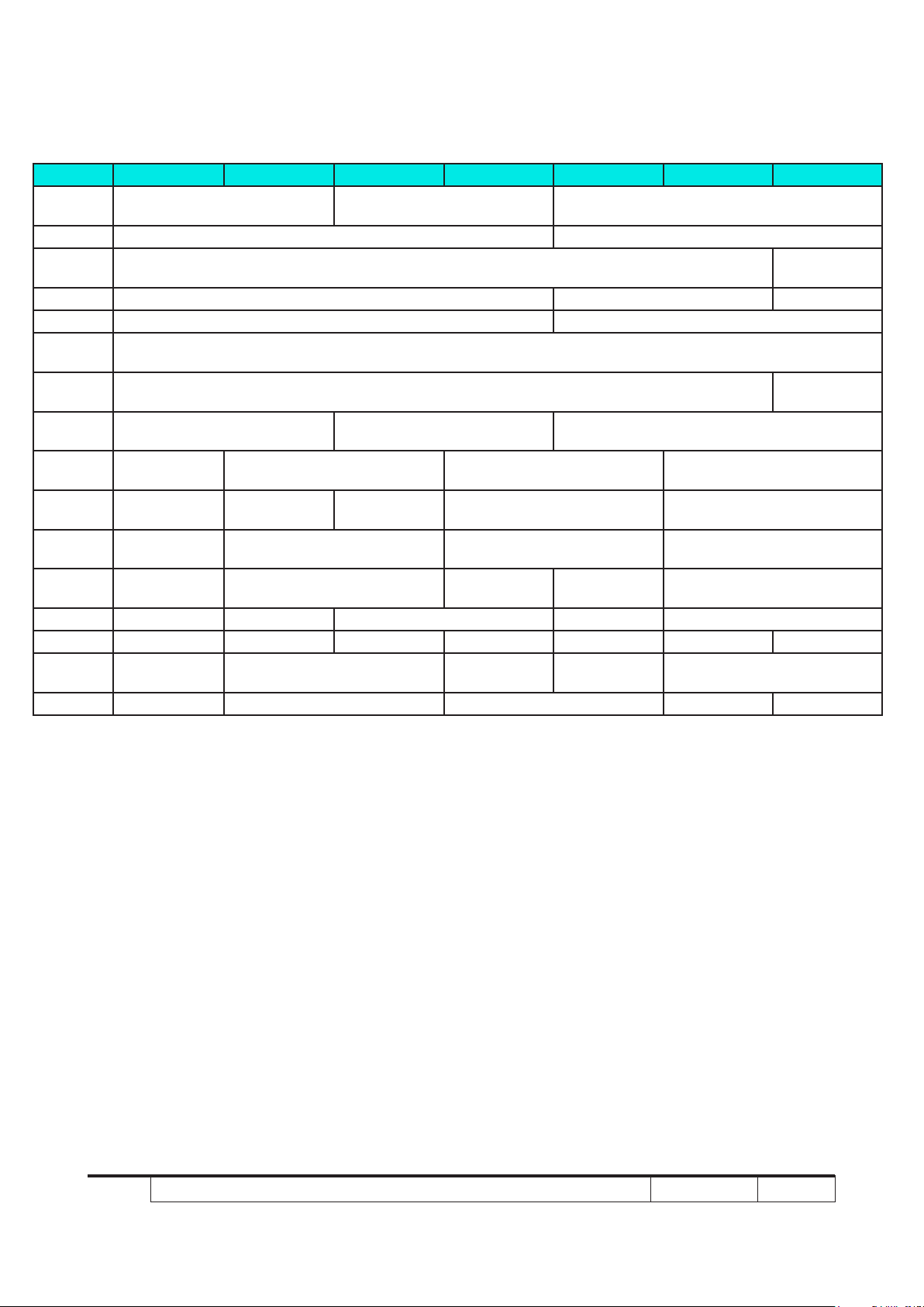
PARTS X1160 X1160refresh X1160Zrefresh X1160Z X1260 X1260refresh X1260Krefresh
LOGO
MYLAR
IO MYLAR 35.88T01G001 35.89B01G001
THERMAL
SWITCH
DMD 48.87K01G001 48.87M01G001 48.89B01G001
SPEAKER N/A 49.89B01G001
BLOWER1
BLOWER2
ZOOM
RING
FRONT IR
CAP
FRONT
COVER
IR SENSOR BD
COLOR
WHEEL
ENGINE 70.88T12GR01 70.88T37GR01 70.88T20GR01 70.89B10GR01 70.89B28GR01
MAIN BD 70.88T13GR01 70.88T36GR01 70.88T38GR01 70.88T21GR01 70.89B07GR01 70.89B27GR01 70.89B43GR01
LAMP
DRIVER
LVPS 75.88T01G101 75.88T08G001 75.88T01G101 75.88T08G001 75.8BE01G001
51.88T03G001 51.88T27G001 75.89B02G001 75.89B01G001 75.89B02G001
70.88T11GR01 70.88T35GR01 70.88T11GR01 70.88T11GR01 70.88T35GR01
70.88T22GR01 70.88T34GR01 70.88T22GR01 70.88T22GR01 70.88T34GR01
35.88T02G001 35.88T03G001 35.89B02G001
N/A 43.89T17G001
49.88T01G001
N/A 49.86E02G001
N/A 51.89B04G001 51.89B04G001
N/A 51.88T24G001 N/A 51.88T24G001
N/A 80.87Y05G001 N/A 80.87Y05G001
X1160 Series/X1260 Series/X1160Z Series/X1260K Refresh
Condential
Page 3

Preface
This manual is applied to X1160 Series/X1260 Series/X1160Z Series/X1260K Refresh
projection system. The manual gives you a brief description of basic technical information
to help in service and maintain the product.
Your customers will appreciate the quick response time when you immediately identify
problems that occur with our products. We expect your customers will appreciate the
service that you offer them.
This manual is for technicians and people who have an electronic background. Please
send the product back to the distributor for repairing and do not attempt to do anything that
is complex or is not mentioned in the troubleshooting.
Notice:
The information found in this manual is subject to change without prior notice. Any
subsequent changes made to the data herein will be incorporated in future edition.
X1160 Series/X1260 Series/X1160Z Series/X1260K Refresh Service Manual
Copyright October.2008
All Rights Reserved
Manual Version 4.0
X1160 Series/X1260 Series/X1160Z Series/X1260K Refresh
Condential
Page 4

X1160 Series/X1260 Series/X1160Z Series/X1260K Refresh
Condential
Table of Content
Chapter 1 Introduction
Highlight 1-1
Compatible Mode 1-3
Product Overview 1-5
Chapter 2 Disassembly Process
Equipment Needed & Product Overview 2-1
Disassemble Lamp Cover Module 2-2
Disassemble Lamp Module 2-2
Disassemble Top Cover Module 2-3
Disassemble Top Shielding 2-4
Disassemble Front Cover Module 2-4
Disassemble Main Board Module & Back Cover Module 2-6
Disassemble Color Wheel Module 2-8
Disassemble Engine Module 2-9
Disassemble DMD Board and DMD Chip 2-10
Disassemble Speaker Module(For X1260 Refresh/X1260 only)
2-11
Disassemble Fan Module 2-12
Disassemble Interrupt Switch Module 2-13
Disassemble Lamp Driver Module 2-14
Disassemble LVPS Module 2-15
Disassemble Bottom Cover Module 2-16
Rod Adjustment 2-17
Re-write Lamp Usage Hour 2-18
Assemble Bottom Cover Module 2-19
Page 5

X1160 Series/X1260 Series/X1160Z Series/X1260K Refresh
Condential
Assemble LVPS Module 2-20
Assemble Lamp Driver Module 2-21
Assemble Interrupt Switch Module 2-22
Assemble Fan Module 2-23
Assemble Speaker Module(For X1260 Refresh/X1260 only)
2-24
Assemble DMD Board and DMD Chip 2-25
Assemble Engine Module 2-26
Assemble Color Wheel Module 2-27
Assemble Main Board Module & Back Cover Module 2-28
Assemble Front Cover Module 2-30
Assemble Top Shielding 2-31
Assemble Top Cover Module 2-32
Assemble Lamp Module 2-33
Chapter 3 Troubleshooting
LED Lighting Message 3-1
Main Procedure 3-2
Beep Sound 3-3
Chapter 4 Function Test & Alignment Procedure
Test Equipment Needed 4-1
Service Mode 4-1
OSD Reset 4-1
Test Condition 4-2
Test Inspection Procedure 4-3
PC Mode 4-3
Calibration 4-7
Video Performance 4-9
Page 6

Optical Performance Measure 4-11
Other 4-12
Chapter 5 Firmware Upgrade
Equipment Needed 5-1
DLP Composer Lite Setup Procedure 5-2
USB Driver Upgrade Procedure 5-4
Firmware Upgrade Procedure 5-5
Waveform Download 5-8
Chapter 6 EDID Upgrade
EDID Introduction 6-1
Equipment Needed 6-2
Setup Procedure 6-3
EDID Key-In Procedure 6-4
Appendix A
Exploaded Overview
I
Appendix B
SerialNumberSystemDenition XXIV
PCBACodeDenition XXV
Appendix C
RS232 function command summary table I
Default Language Reset 6-5
X1160 Series/X1260 Series/X1160Z Series/X1260K Refresh
Condential
Page 7

Chapter 1
Introduction
1-1 Highlight
No Item Description
1 Dimensions (LxWxH) - 267 mm x 187 mm x 80 mm
2 Weight - <5 lbs
- 7 degree with elevator mechanism
(for X1160/X1260/ X1160Z)
3 Tilt Angle
4 Power Supply
5 Keystone correction - +/- 40 degree (80 degree)
6 Cooling system
7 Brightness
- 3 degree with elevator mechanism
(for X1160 refresh /X1260 refresh/X1160Z refresh/X1260K
refresh)
- Universal AC 100 – 240 V ~ 50-60 Hz with PFC input
- 160W for Osram E20.6 Lamp @ normal operation
(for x1160 series/x1260 series/x1160z series)
- 180W for Osram E20.6 Lamp @ normal operation
(only for x1260k refresh)
- Variant FAN speed control (Depends on temperature
variance)
- Advanced Air Flow
- One fan with system acoustic noise level 36 dB(A) (typical)
- Temperature control circuits with adaptive fan rotational
speeds
- Maximum touch temperature follow UL60950-1
Engineering Spec:
- 1700 ANSI Lumens (Typical) (for X1160/X1260/X1160Z)
- 1445 ANSI Lumens (Minimum) (for X1160/X1260/X1160Z)
- 1800 ANSI Lumens (Typical)
( for X1160 refresh/X1260 refresh/X1160Z refresh/X1260K
refresh)
- 1600 ANSI Lumens (Minimum)
(for X1160 refresh /X1260 refresh/X1160Z refresh/X1260K
refresh)
Marketing Spec:
- 2000 ANSI Lumens
X1160 Series/X1260 Series/X1160Z Series/X1260K Refresh
Condential 1-1
Page 8

X1160 Series/X1260 Series/X1160Z Series/X1260K Refresh
Condential
1-2
No Item Description
Engineering Spec:
- 1500 : 1 Full White and Black (Minimum; Full power mode)
(for X1160/X1260/X1160Z)
- 1800 : 1 Full White and Black (Typical; Full power mode)
(for X1160/X1260/X1160Z)
- 1400 : 1 Full White and Black (Minimum; Full power mode)
8 Contrast
9 Uniformity
10 Throw ratio
11 Lamp door protection
12 Projection lens
13 Lamp life - 3500 hours min, 50% survival rate
14 System controller - TI DDP2230
15 Terminal
(for X1160 refresh/X1260 refresh/X1160Z refresh)
- 1800 : 1 Full White and Black (Typical; Full power mode)
(for X1160 refresh/X1260 refresh/X1160Z refresh)
- 400 : 1 Full White and Black (Minimum; Full power mode)
- 600 : 1 Full White and Black (Typical; Full power mode)
(only for X1260K refresh)
Marketing Spec:
- 2000:1
Engineering Spec:
- 65% Japan standard (Minimum; Full power mode)
- 80% Japan standard (Typical; Full power mode)
Marketing Spec:
- 85%
- 1.95:1 distance/width @60”(For X1160 refresh /X1160)
- 1.95 – 2.15:1 distance/width @60” (For X1260 refresh /
X1260/X1160Z/X1160Z refresh/X1260K refresh)
- Lamp Power Supply shut off automatically when lamp
cover open
- F# 2.41 ,f = 21.79mm, Fix lens (For X1160 refresh /X1160)
- F# 2.41~2.55, f = 21.79~23.99 mm, 1.10X Mechanical
Zoom Lens (For X1260 refresh/X1260/X1160Z/X1160Z
refresh/X1260K refresh)
For X1160 refresh/X1160
- One D-sub VGA input
- One Composite input
- One S-Video input(4 pin Mini din)
- One USB port (Type B Female)
For X1260 refresh/X1260/X1260K refresh
- One D-sub VGA input
- One D-sub VGA output
- One Composite input
- One S-Video input(4 pin Mini din)
- One audio input (2.5m phone jack)
- One USB port (Type B Female)
- One RS-232 (3 pin Mini din)
Page 9

X1160 Series/X1260 Series/X1160Z Series/X1260K Refresh
Condential
1-3
No Item Description
- Number of active dots : 800(H) x 600(V) (for X1160/
16 Number of active dots
17 Input signal spec.
18 TI DMD
19 Video compatibility
20 Power consumption
21 Color wheel
22 Lamp
X1160 refresh/1160Z/X1160Z refresh)
- Number of active dots : 1024(H) x 768(V) (for
X1260/X1260 refresh/X1260K refresh)
- Hsync Frequency 31 ~ 69 kHz (for X1160 refresh/X1160/
X1160Z/X1160Z refresh)
- Hsync Frequency 31 ~ 80 kHz (for X1260 refresh/X1260K
refresh)
- Vsync Frequency 50 ~ 85 Hz
- Video Signal RGB (PC)
● Analog RGB 0.7Vp-p, 75 ohm, Separate TTL H,V Sync
● Analog RGB 1Vp-p, 75 ohm, Sync. On Green signal
● Analog RGB 0.7Vp-p, 75 ohm, Composite TTL Sync
- Video
● Composite video 1Vp-p,75 ohm
● S-video Luminance 0.714Vp-p, 75 ohm,Chrominance
0.286Vp-p, 75 ohm
● Component Video 1Vp-p, 75 ohm
- TI DMD 0.55” 12° 2xLVDS Type-X SVGA Digital Mirror
Device (for X1160/X1160 refresh/X1160Z/X1160Z refresh)
- TI DMD 0.55” 12° 2xLVDS Type-X XGA Digital Mirror De
vice (for X1260 refresh/X1260/X1260K refresh)
- Standards :
● NTSC (3.58/4.43)
● PAL (B/D/G/H/I/M/N)
● SECAM (B/D/G/K/K1/L)
● HDTV - 480i, 576i, 480p, 576p, 720p, 1080i
- 225W Max
- Standby < 8W at AC 110V (for X1160/X1260/X1160Z)
- Standby < 5W at AC 110V
(for X1160 refresh/X1260 refresh/X1160Z refresh)
- 250W Max.
- Standby < 5W at AC 110V
(only for X1260K refresh)
- 6 segments (R90/Y28/G90/C28/W42/B82)
- 7200 rpm
- 9000 rpm @ CW 3X, PAL 50Hz
(for X1160 refresh/X1260 refresh/X1160Z refresh/X1260K
refresh)
- 160 Watt OSRAM (for X1160 Series/X1260 Series/X1160Z
Series)
- 180 Watt OSRAM (only for X1260K refresh)
23 Temperature
- Operating: 5°C -- 35°C
- Storage: -20°C -- 60°C
Page 10
X1160 Series/X1260 Series/X1160Z Series/X1260K Refresh
Condential
1-4
1-2 Compatible Mode
VGA Analog - PC Signal
Compatibility Resolution V-Sync [Hz] H-Sync [KHz]
640x480 60 31.50
640x480 72 37.90
VGA
SVGA
XGA
SXGA
QuadVGA
640x480 75 37.50
640x480 85 43.30
720x400 70 31.50
720x400 85 37.90
800x600 56 35.10
800x600 60 37.90
800x600 72 48.10
800x600 75 46.90
800x600 85 53.70
832x624 75 49.70
1024x768 60 48.40
1024x768 70 56.50
1024x768 75 60.00
1024x768 85 68.70
1152x864 70 63.80
1152x864 75 67.50
1280x1024 60 64.00
1152x864
(For X1260/X1260 refresh/X1260K refresh)
1280x1024
(For X1260/X1260 refresh/X1260K refresh)
1280x1024
(For X1260/X1260 refresh/X1260K refresh)
1280x960 60 60.00
1280x960
(For X1260/X1260 refresh/X1260K refresh)
85 77.10
72 77.00
75 80.00
75 75.20
Page 11
X1160 Series/X1260 Series/X1160Z Series/X1260K Refresh
Condential
1-5
VGA Analog - Extended Wide timing
Compatibility Resolution V-Sync [Hz] H-Sync [KHz]
1280x768 60 48.36
1280x768 75 60.30
1280x720 60 44.80
WXGA
1280x768
(For X1260/X1260 re-
fresh/X1260K refresh)
1280x800 60 49.60
1440x900 60 59.90
85 68.60
Page 12
X1160 Series/X1260 Series/X1160Z Series/X1260K Refresh
Condential
1-6
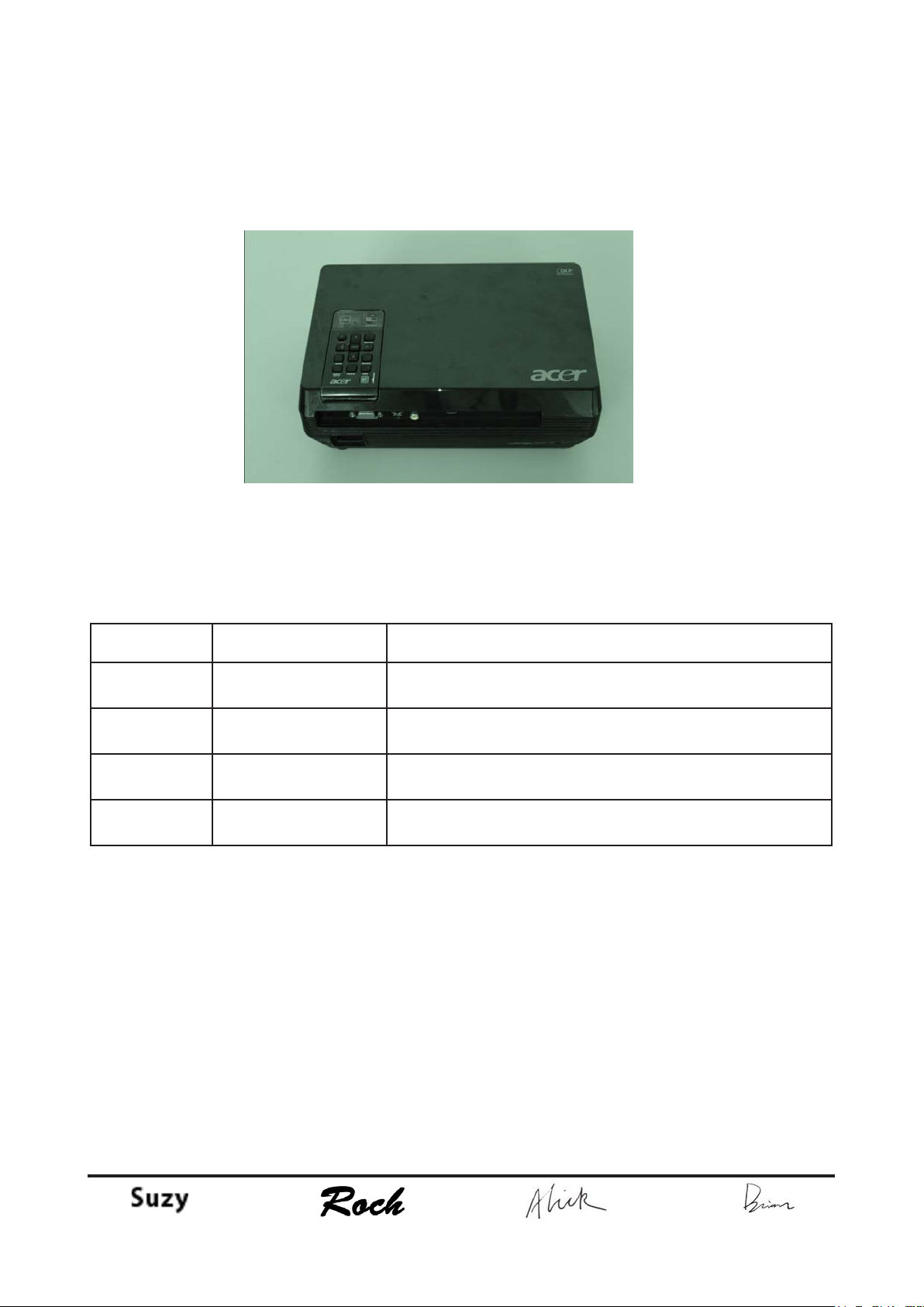
Product Overview
Projector Outlook
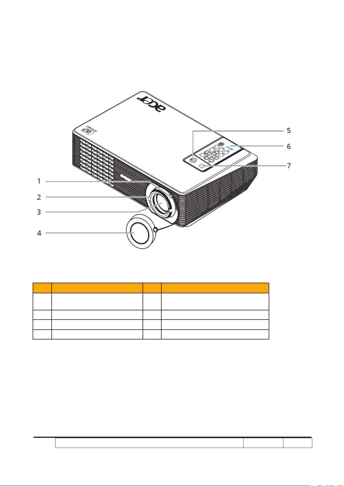
Front /Upper side
Item Description Item Description
Zoom ring (X1260 series/
1
X1260K Refresh)
2 Focus ring 6 Remote controller
3 Zoom lens 7 Remote control receiver
4 Lens cap
Power button and Power Indicator
5
LED
Page 13
X1160 Series/X1260 Series/X1160Z Series/X1260K Refresh
Condential
1-7
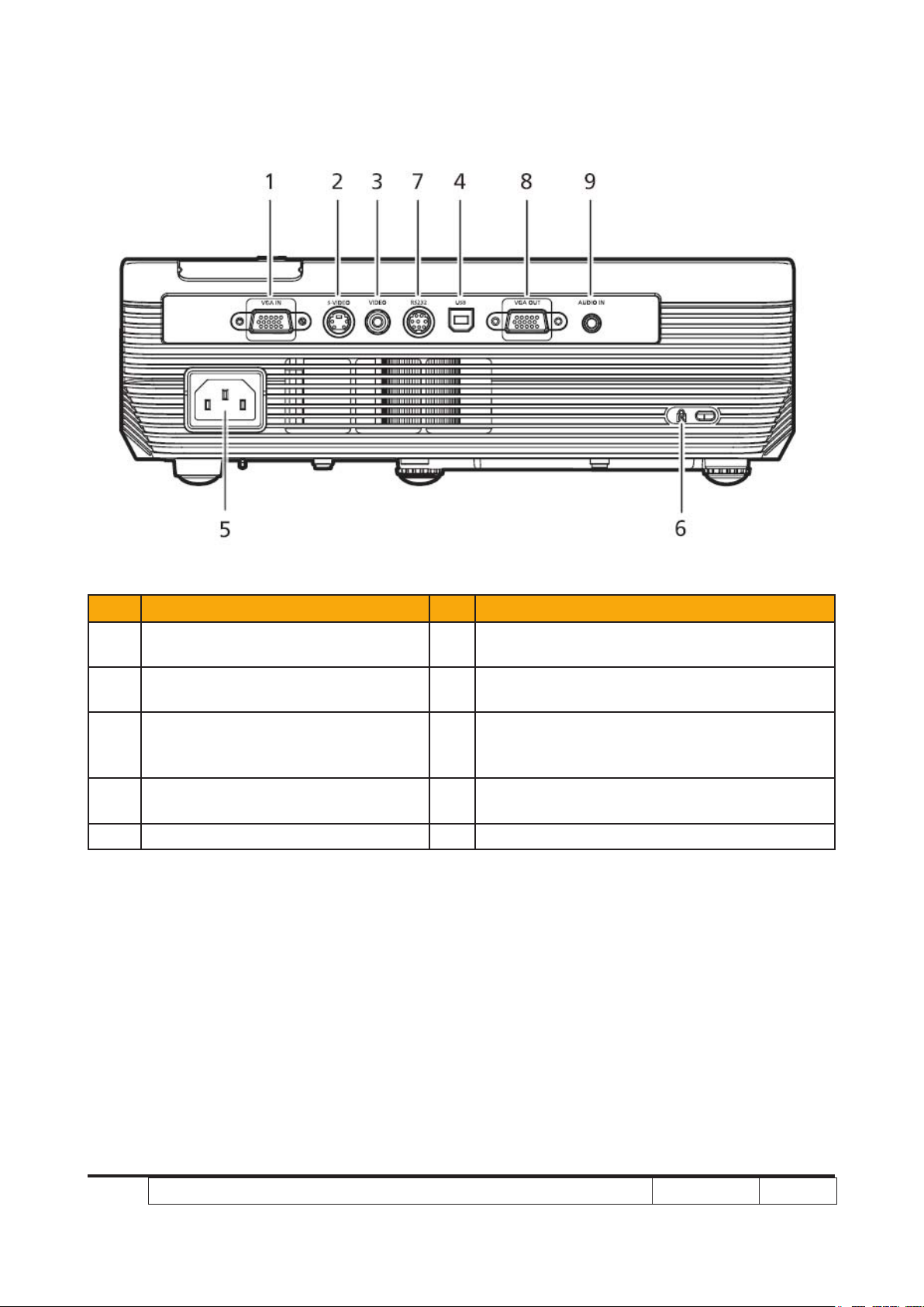
Rear side
Item Description Item Description
PC analog signal/HDTV/component
1
video input connector
2 S-Video input connector 7
3 Composite video input connector 8
4 USB connector 9
5 Power socket
6 KensingtonTM lock port
RS232 connector (Only for X1260 refresh/
X1260/X1260K refresh)
Monitor loop-through output
connector (VGA-Out) (Only for X1260 refresh/
X1260/X1260K refresh)
Audio input connector (Only for X1260 refresh/X1260/X1260K refresh)
Page 14
X1160 Series/X1260 Series/X1160Z Series/X1260K Refresh
Condential
1-8
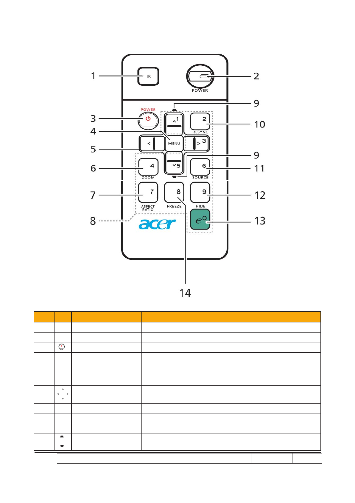
Remote Control and Control Panel Layout
Item Icon Function Description
1 Infrared transmitter Sends signals to the projector.
2 Power/Power LED Power button and Power Indicator LED.
3 POWER Refer to the “Turning the Projector On/Off” section.
• Press “MENU” to launch the Onscreen display (OSD)
4 MENU
5
6 ZOOM Zooms the projector display in or out.
7 ASPECT RATIO To choose the desired aspect ratio (Auto/4:3/16:9).
8 KeyPad 0~9 Press “0~9” to input a password in the “Security settings”.
9 KEYSTONE
Four directional select
keys
menu, back to the previous step for the OSD menu
operation or exit the OSD menu.
• Conrm your selection of items.
Use up, down, left, right buttons to select items or make
adjustments to your selection.
Adjusts the image to compensate for distortion caused by
tilting the projector (± 40 degrees).
Page 15
X1160 Series/X1260 Series/X1160Z Series/X1260K Refresh
Condential
1-9
Item Icon Function Description
10 RESYNC
11 SOURCE
12 HIDE
13
14 FREEZE To pause the screen image.
Empowering
key
Automatically synchronizes the projector to the input
source.
Press “SOURCE” to choose RGB, Component, S-Video,
Composite and HDTV sources.
Momentarily turns off the video. Press “HIDE” to hide the
image, press again to display the image.
Unique Acer functions: eView, eTimer Management.
Page 16
X1160 Series/X1260 Series/X1160Z Series/X1260K Refresh
Condential
1-10
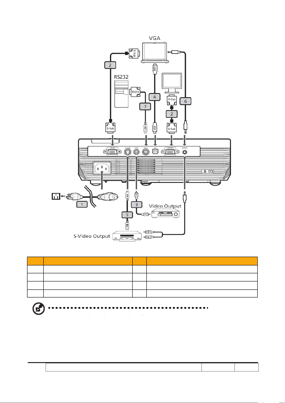
Connecting the Projector
Item Description Item Description
1 Power cord 5 S-Video cable
2 VGA cable 6 Audio cable jack/jack
3 Composite video cable 7 RS232 cable
4 USB cable
Note: To ensure the projector works well with your computer,please make sure the timing of
the display mode is compatible with the projector.
Page 17
X1160 Series/X1260 Series/X1160Z Series/X1260K Refresh
Condential
1-11
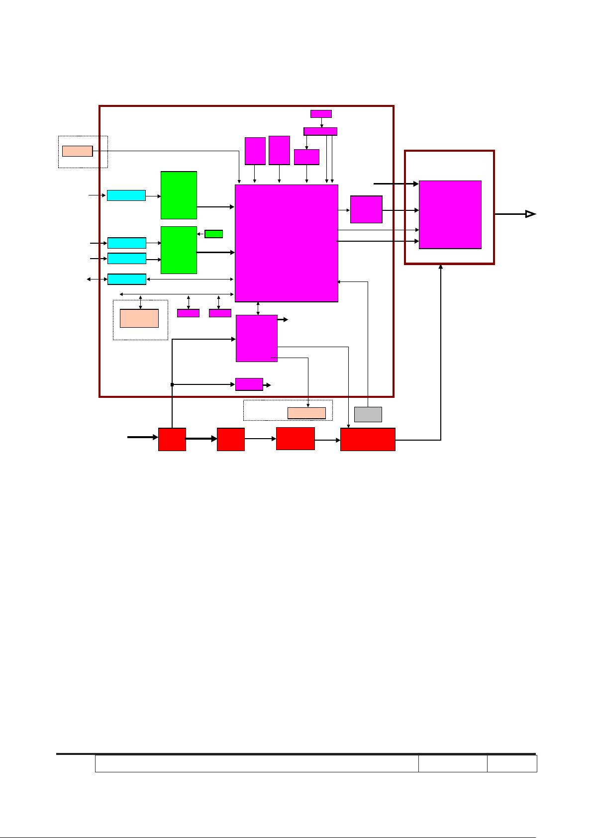
X1160 Refresh/X1160/X1160Z Refresh/X1160Z
ADC
AD9883A
Svideo
Input
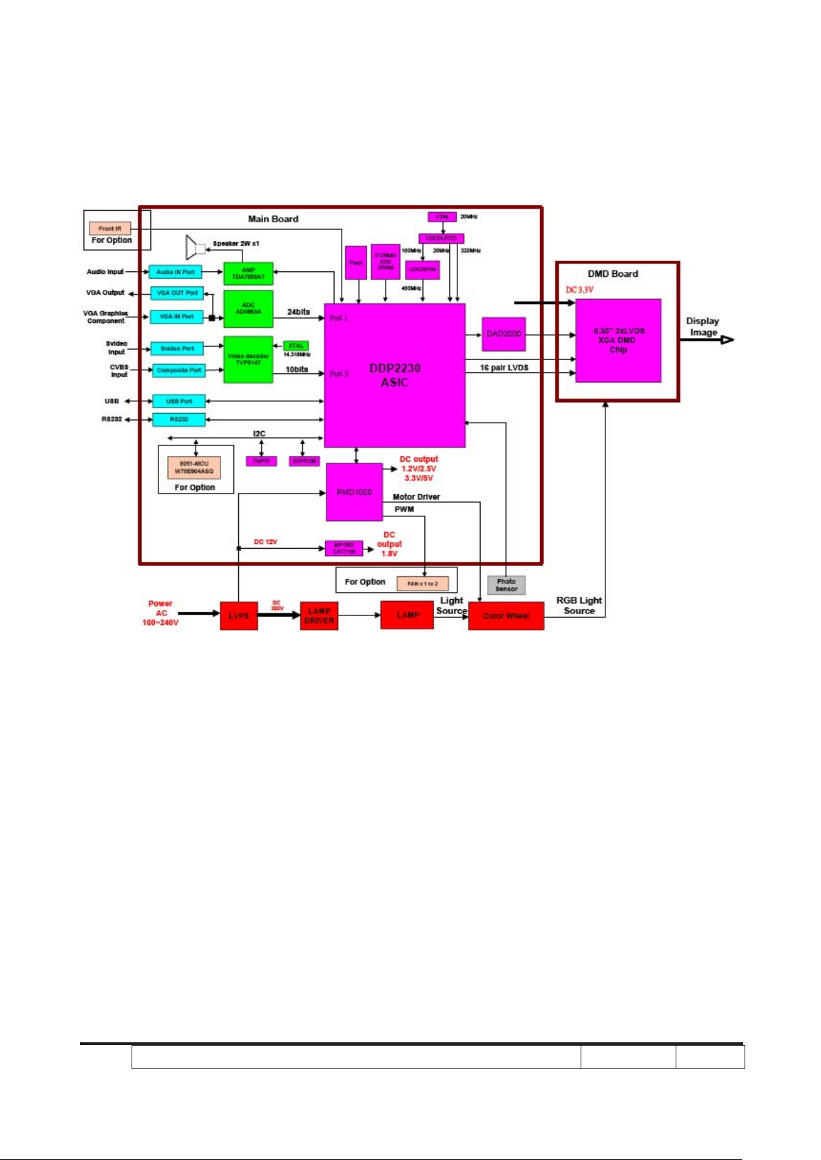
DDP2230
ASIC
DAD2000
0.55" 2xLVDS
SVGA DMD
Chip
Display
Image
Color Wheel
RGB Light
Source
LAMP
Light
Source
LVPS
DC 12V
LAMP
DRIVER
DC
380V
Power
AC
100~240V
Photo
Sensor
CVBS
Input
VGA IN Port
USB
Input
VGA Graphics
Component
Video decoder
TVP5147
Flash
512Mbits
XDR
DRAM
CDCD5704
CDCDLP223
XTAL
PMD1000
MP1583
CAT7106
TMP75 EEPROM
16 pair LVDS
DC output
1.2V/2.5V
3.3V/5V
20MHz
20MHz 320MHz100MHz
400MHz8 bits
FAN x 1 to 2
PWM
Motor Driver
DC
output
1.8V
P o r t 1
P o r t 3
Svideo Port
Composite Port
USB Port
Main Board
24bits
10bits
XTAL
DMD Board
D C 3.3V
14.318MHz
8051-MCU
W79E804ASG
Front IR
I2C
For Option
For Option
For Option
Page 18
X1160 Series/X1260 Series/X1160Z Series/X1260K Refresh
Condential
1-12
X1260 Refresh/X1260/X1260K Refresh
Page 19
X1160 Series/X1260 Series/X1160Z Series/X1260K Refresh
Condential
1-13
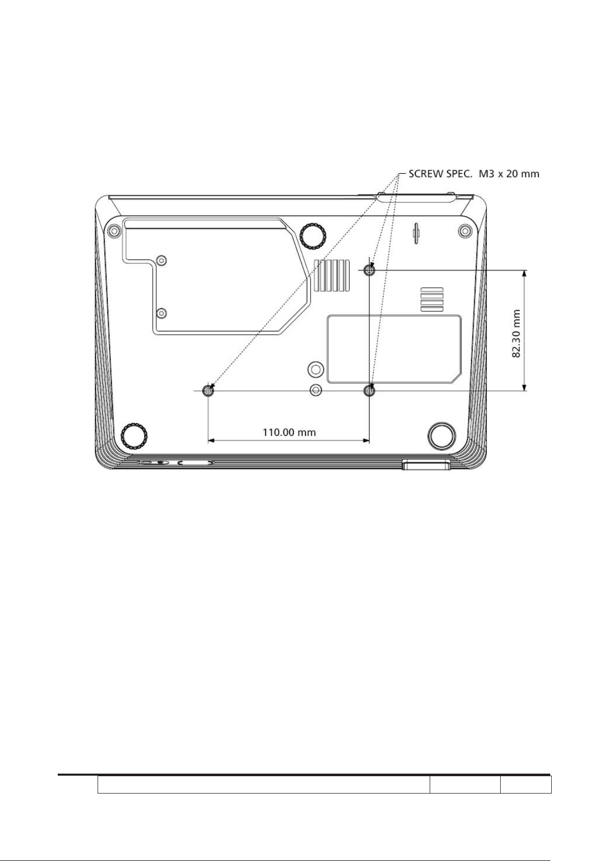
Bottom Cover Dimension
Page 20
Chapter 2
Disassembly& Assembly Process
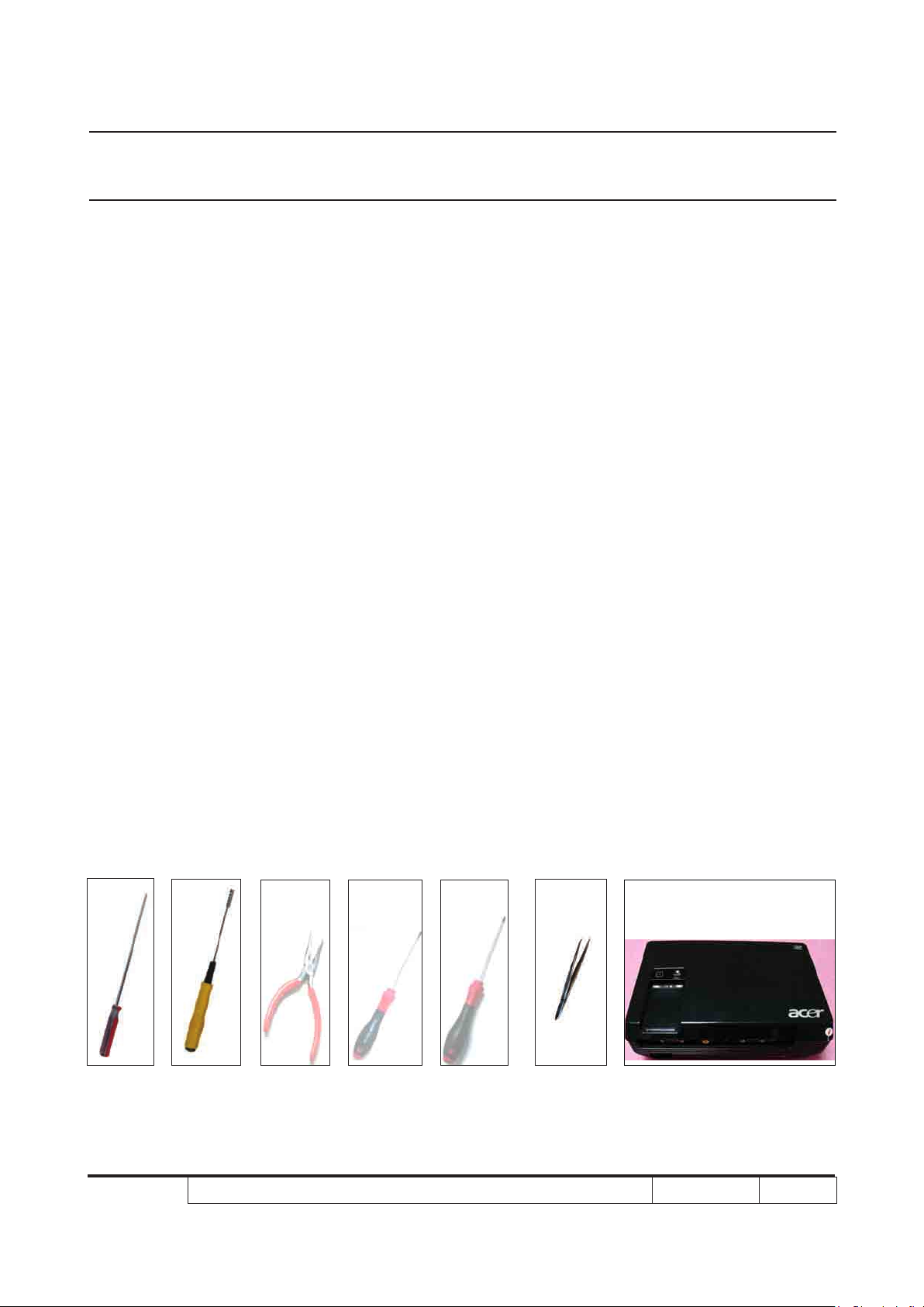
2-1 Equipment Needed & Product Overview
1. Screw Bit (+) :107
2. Hex Sleeves 5mm
3. Screw Bit (+) :102
4. Screw Bit (-) :102
5. Long Nose Nipper
6. Tweezers
X1160/X1160 refresh/X1260/X1260 refresh/X1160Z/X1160Z refresh/X1260K refresh
7.
* Before you start: This process is protective level II. Operators should wear electrostatic chains.
unit
* Note: 1.If you need to replace the main board, you have to get into service mode and record the
lamp usage hour. please refer to section 2-18.
2.The disassembly and assembly process for X1160 Series/X1260 Series/X1160Z Series/
X1260K Refresh is the same. Here, we take X1160/X1260 as example.
X1160 Series/X1260 Series/X1160Z Series/X1260K Refresh Condential
2-1
Page 21
X1160 Series/X1260 Series/X1160Z Series/X1260K Refresh Condential 2-2
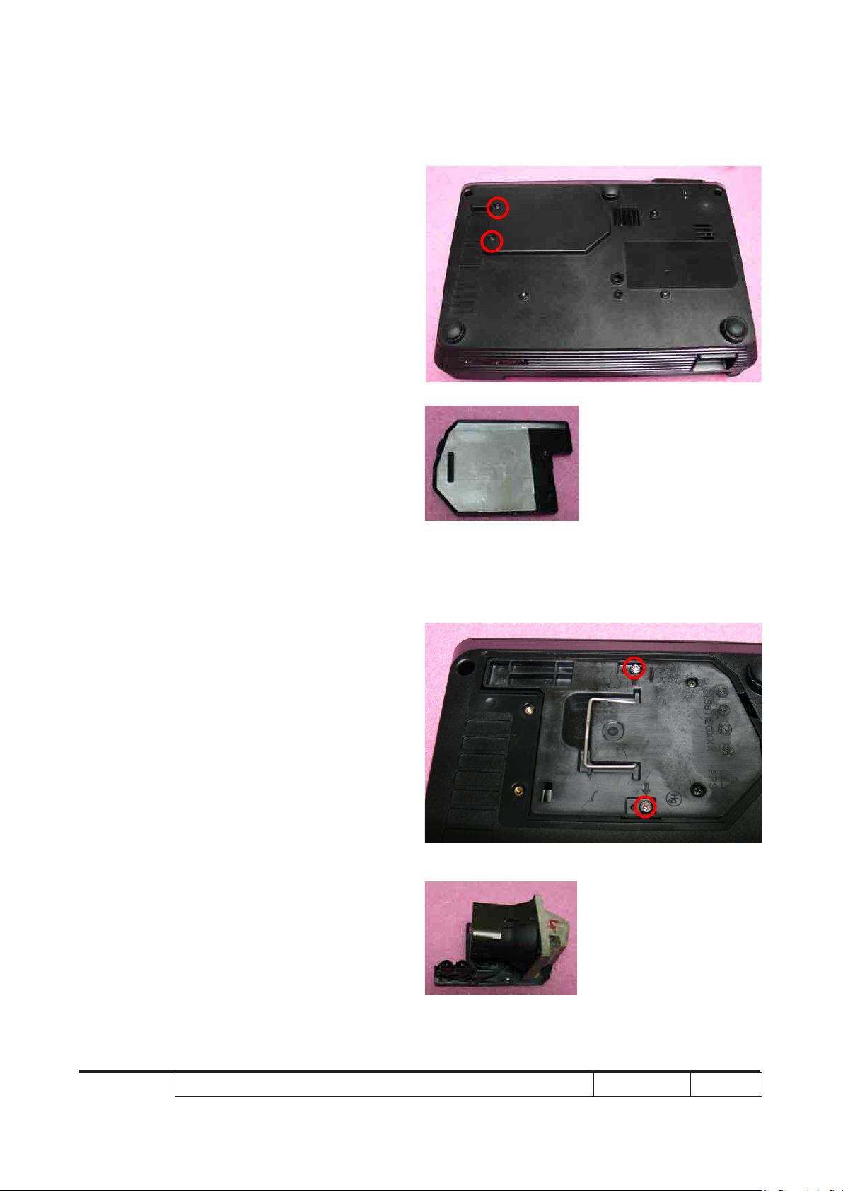
2-2 Disassemble Lamp
Cover Module
1. Unscrew 2 screws on the lamp cover
module
Lamp Cover Module
2-3 Disassemble Lamp
Module
1. Unscrew 2 screws on the lamp module
Lamp Module
Page 22
X1160 Series/X1260 Series/X1160Z Series/X1260K Refresh Condential 2-3
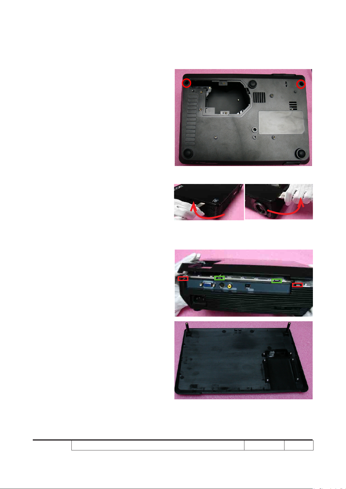
2-4 Disassemble Top Cover
Module
1. Unscrew 2 screws on the unit base
2. Use the tweezers to scratch sharply on
the both side
Note:You’d better drop out two tenons in
the back side before disassemble the top cover
module.(As the red square) And then the rest
of the two tenons will be spontaneously fall.(As
the green square)
Top Cover Module
Page 23
X1160 Series/X1260 Series/X1160Z Series/X1260K Refresh Condential 2-4
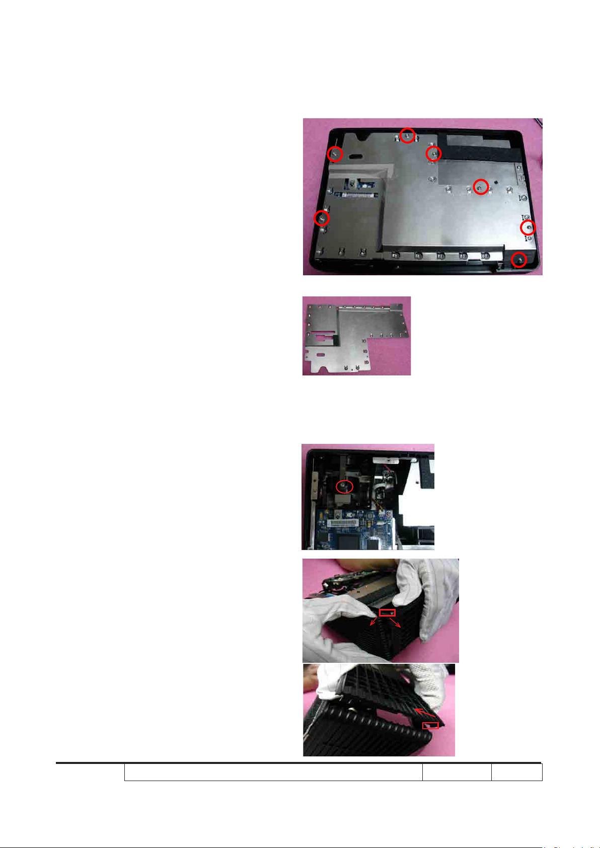
2-5 Disassemble Top
Shielding
1. Unscrew 7 screws on the top shielding
2-6 Disassemble Front Cover
Module
1. Unscrew 1 screw on front cover module
(Only for X1260/X1260 Refresh/X1260
Refresh)
2. Press four tenons to disassemble the
front cover module
- First,disassemble right side of front cover:
Push the top side of bottom cover to right
and push the top side of the front cover to
front,then one tenon will be out.Push the
front cover to above,then another tenon
will be out.
Page 24
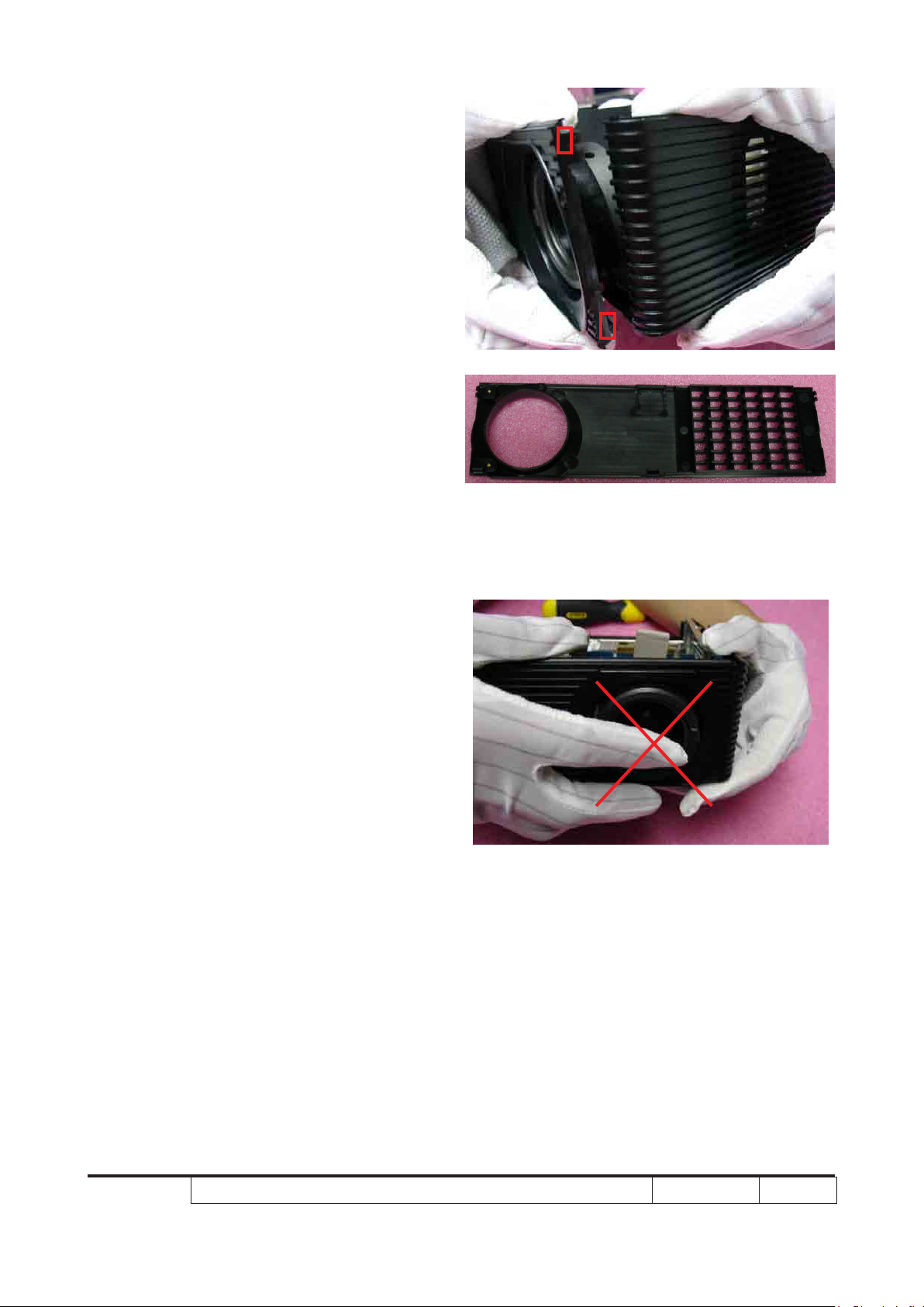
X1160 Series/X1260 Series/X1160Z Series/X1260K Refresh Condential 2-5
- Then,the left side of the front cover is
the same as the right side
Front Cover Module
Note: Avoid touch the lens when disassem ble the front cover.
Page 25
X1160 Series/X1260 Series/X1160Z Series/X1260K Refresh Condential 2-6
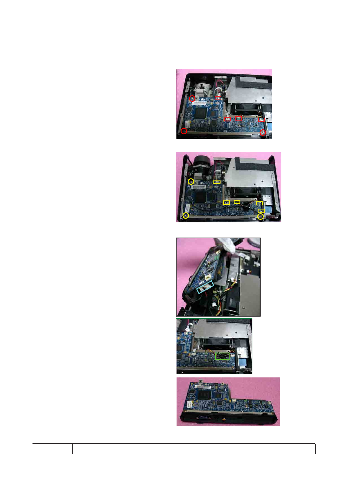
2-7 Disassemble Main Board
Module & Back Cover
Module
1. Unscrew 3 screws and 5 connectors
on main board module & back cover
module(X1160/X1160 Refresh/X1160Z/
X1160Z refresh)
Unscrew 3 screws and 6 connectors
on main board module & back cover
module(X1260/X1260 Refresh/X1260K
Refresh)
Note:Speaker Cable(only for X1260/X1260
Refresh/X1260K Refresh)& Fan Cable must
be xed on Main Board by lm tape to avoid to
For (X1160/X1160 Refresh/X1160Z/X1160Z refresh)
For X1260/X1260 Refresh/X1260K Refresh
stretch into the Fan.
Main Board Module&Back Cover Module
Page 26
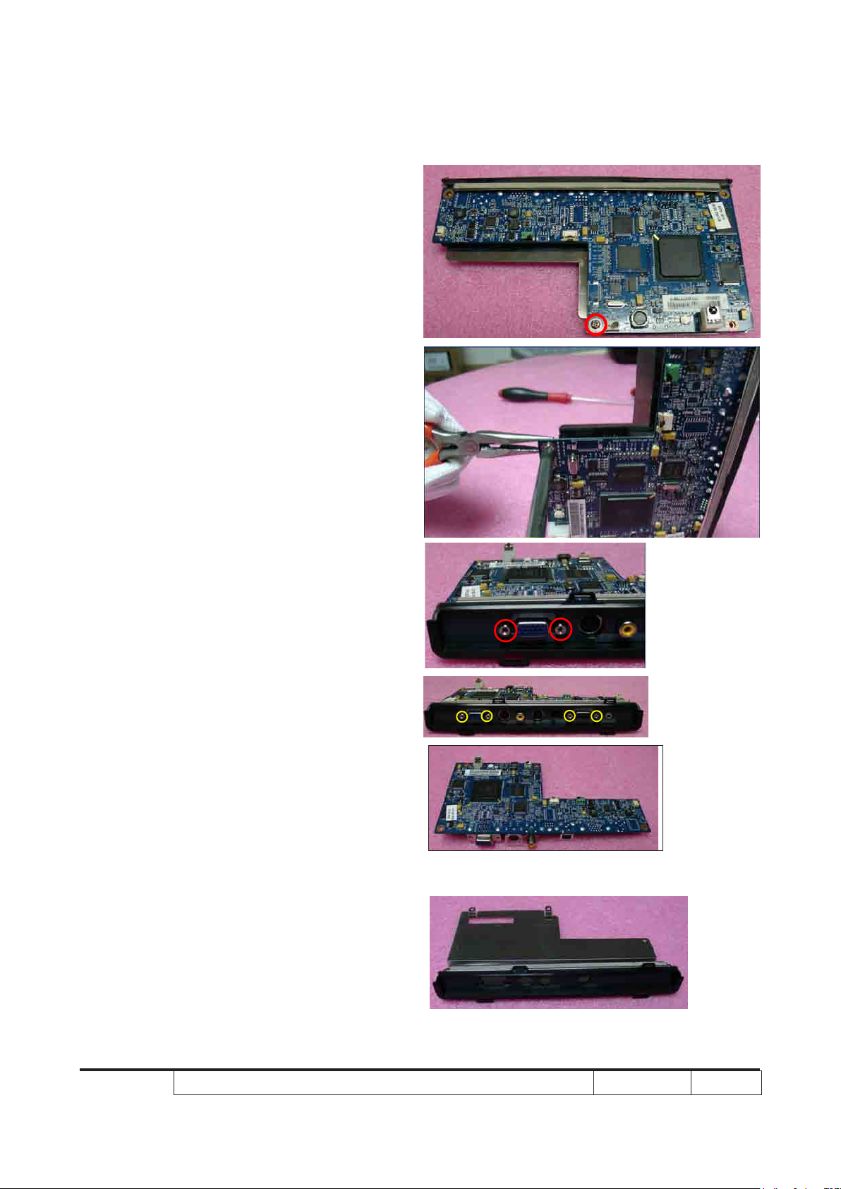
X1160 Series/X1260 Series/X1160Z Series/X1260K Refresh Condential 2-7
2. Unscrew 1 screw on main board module
& back cover module
Note:Use the Long Nose Nipper to lock the hex
screw nut.
3. Unscrew 2(4 for X1260/X1260 Refresh/
X1260K Refresh) hex screws on main
board module & back cover module
Main Board Module
Back Cover Module
For (X1160/X1160
Refresh/X1160Z/
X1160Z refresh)
For (X1260/X1260
Refresh/X1260K
Refresh)
Page 27
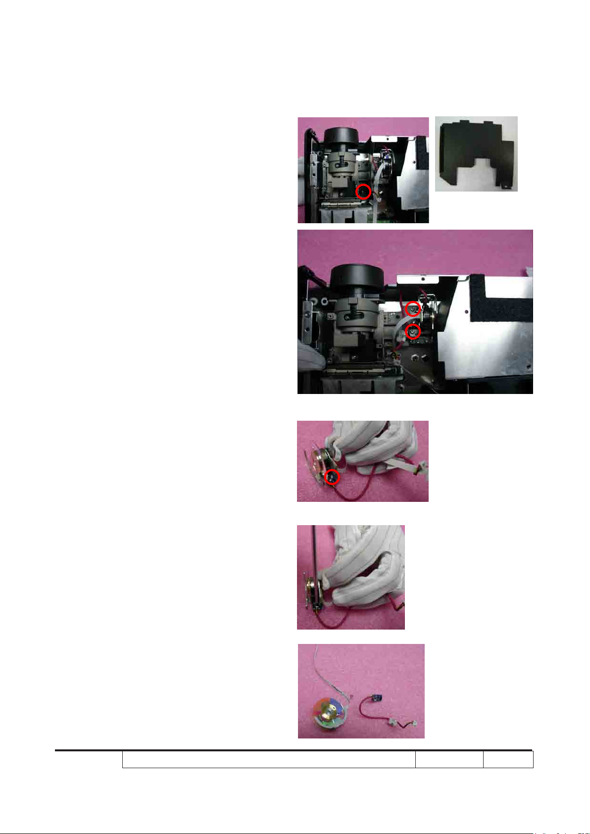
X1160 Series/X1260 Series/X1160Z Series/X1260K Refresh Condential 2-8
2-8 Disassemble Color
Wheel Module
1. Unscrew 1 screw on mylar
2. Unscrew 2 screws on color wheel
module
3. Unscrew 1 screw on photo sensor
Mylar
Page 28
X1160 Series/X1260 Series/X1160Z Series/X1260K Refresh Condential 2-9
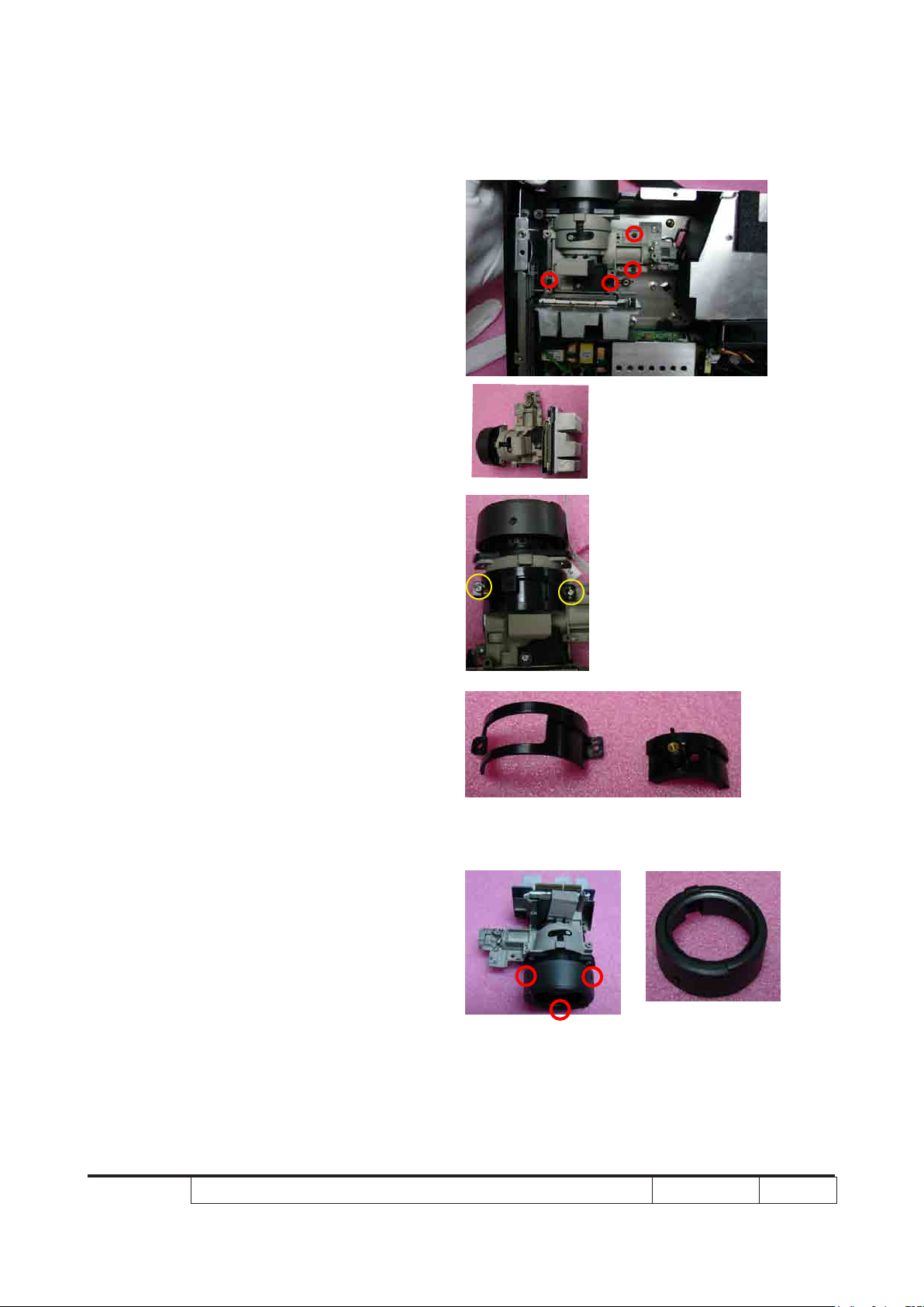
2-9 Disassemble Engine
Module
1. Unscrew 4 screws on engine module
2. Unscrew 2 screws on engine module to
disassemble the zoom ring and zoom
ring holder(X1260/X1260 Refresh/
X1260K Refresh only)
3. Unscrew 3 screws on focus ring
Engine Module
For (X1260/
X1260 Refresh/
X1260K Refresh)
Zoom Ring Holder and Zoom Ring For (X1260/X1260
Refresh/X1260K Refresh)
Focus Ring
Page 29
X1160 Series/X1260 Series/X1160Z Series/X1260K Refresh Condential 2-10
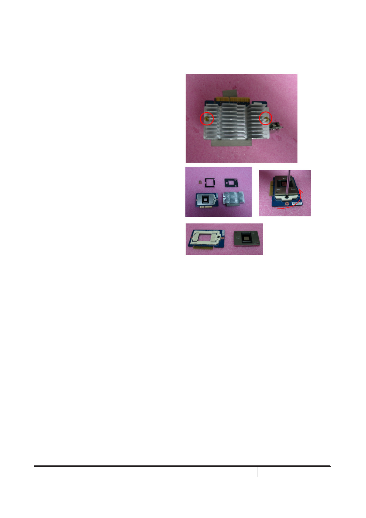
2-10 Disassemble DMD
Board and DMD Chip
1. Unscrew 2 screws on engine module,
disassemble Heat Sink and DMD
Board&DMD chip module
2. Unlock the lockhole by Screw Bit(-) to
disassemble the DMD chip from the
DMD board
Note:It will be unlocked if the Screw Bit(-) turn
reverse. Contrary,It will be locked.
Page 30
X1160 Series/X1260 Series/X1160Z Series/X1260K Refresh Condential 2-11
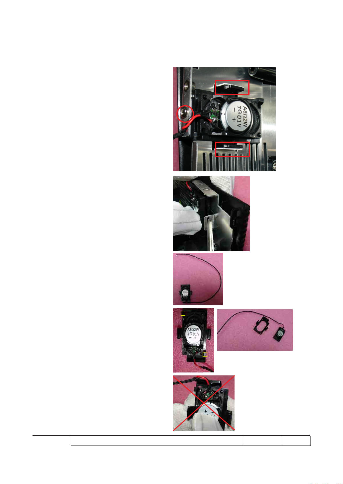
2-11 Disassemble Speaker
Module(For X1260/
X1260 Refresh/X1260K
Refresh)
1. Unscrew 1 screw and press 2 tenons to
disassemble Speaker Module
- Press the plastic of the speaker Holder
and then use the tweezers to press the
tenon.
2. Press two tenons to disassemble the
speaker from the speaker holder
Note:Avoid to press the speaker with great
strenth.
Speaker holder&Speaker
Page 31

X1160 Series/X1260 Series/X1160Z Series/X1260K Refresh Condential 2-12
2-12 Disassemble Fan
Module
1. Unscrew 4 screws on the fan module
Note:The fan cable pass through from the
aperture.
Page 32

X1160 Series/X1260 Series/X1160Z Series/X1260K Refresh Condential 2-13
2-13 Disassemble Interrupt
Switch Module
1. Unplug 1 connector and unscrew 1
screw and disassemble 1 lm tape to
disassemble interrupt switch module
Note: Interrupt switch cable must be pass
through a dent and a aperture.And use a lm
tape to x the cable in the dent.
2. Disassemble interrupt switch from
interrupt switch holder
Film tape
Dent
Aperture
Interrupt Switch Module
Interrupt Switch&holder
Page 33

X1160 Series/X1260 Series/X1160Z Series/X1260K Refresh Condential 2-14
2-14 Disassemble Lamp
Driver Module
1. Unplug 1 connector and unscrew 1 screw
on lamp driver module
2. Unplug 1 connector and unscrew 2
screws on lamp driver to lamp cable
Note: The lamp driver to lamp cable must be pass
through two Dents.(As the yellow square)
3. Unplug 2 connectors to disassemble
3PIN and 5PIN cable
Note:The 3 PIN and 5 PIN cable must be pass
through a Dent.(As the yellow square)
1
2
Lamp Driver to Lamp Cable
4. Unscrew 4 screws on lamp driver module
3
3 PIN&5 PIN Cable
4
Lamp Driver Holder
Lamp Driver Module
Page 34

X1160 Series/X1260 Series/X1160Z Series/X1260K Refresh Condential 2-15
2-15 Disassemble LVPS
Module
1. Unscrew 1 ground screw(As red circle)
2. Unscrew 1 screw on LVPS module(As
yellow circle)
3. Disassemble LVPS BRKT
4. Unscrew 3 screws on LVPS module(As
green circle)
LVPS BRKT
LVPS Module
Page 35

X1160 Series/X1260 Series/X1160Z Series/X1260K Refresh Condential 2-16
2-16 Disassemble Bottom
Cover Module
1. Unscrew 1 screw on bottom cover
module
2. Disassemble 1 EMI tape
3. Disassemble the bottom cover shielding
from bottom cover module
4. Press two tenons to disassemble the
ROD DUCT
- Pull aside the iron sheet with Tweezers
to disassemble the ROD DUCT
Note: Due to the iron sheet was out of shape,so
we must turn it back before assemble the ROD
DUCT.
ROD DUCT
Page 36

X1160 Series/X1260 Series/X1160Z Series/X1260K Refresh Condential 2-17
2-17 Rod Adjustment
1. environment adjustment
- The distance between the engine and the
Bottom Cover Module
Screw 2
screen is 1.7 M
- This process should be done at a dark
environment. (under 5 Lux)
2. Procedure adjustment
- Change the screen to “white screen.”
- Adjust the screws by using the rod on
the engine module to readjust the image.
(adjust until the yellowish or bluish parts
disappeared.)
Screw 1
Page 37

X1160 Series/X1260 Series/X1160Z Series/X1260K Refresh Condential 2-18
3. Abnormal image inspection
- It should not have any abnormal color at the
rim of the image by estimating through the
eyes.
Note: To avoid over adjust the rod. After the
opration,please use the glue to xed the screws.
2-18 Re-write Lamp Usage
Hour
- Take X1260 for example,X1160/X1160
Refresh/X1260 Refresh/X1160Z/X1160Z
Refresh/X1260K Refresh is the same as
X1260
1. Get into service mode.
- press (power > left > left > menu) to get
into service mode.
2. Use left or right key to re-write the lamp
hour back to previous lamp usage hour.
3. Choose exit
Check the lamp
usage hour
Re-write lamp
usage hour
Page 38

X1160 Series/X1260 Series/X1160Z Series/X1260K Refresh Condential 2-19
2-19 Assemble Bottom
Cover Module
1. Fasten two tenons to assemble ROD
DUCT
2. Assemble the bottom cover shielding on
bottom cover module
3. Stick 1 EMI tape
4. Screw 1 screw on bottom cover module
Bottom Cover shielding
ROD DUCT
Bottom Cover Module
Page 39

X1160 Series/X1260 Series/X1160Z Series/X1260K Refresh Condential 2-20
2-20 Assemble LVPS Module
1. Screw 3 screws on LVPS module(As
green circle)
2. Screw 1 screw to assemble LVPS BRKT
(As yellow circle)
3. Screw 1 ground screw(As red circle)
LVPS BRKT
LVPS Module
Page 40

X1160 Series/X1260 Series/X1160Z Series/X1260K Refresh Condential 2-21
2-21 Assemble Lamp Driver
Module
Lamp Driver Holder
1. Screw 4 screws to assemble lamp driver
module on lamp driver holder
2. Plug 2 connectors to assemble 3PIN and
5PIN cable
Note:The 3 PIN and 5 PIN cable must be pass
through a Dent.(As the yellow square)
Lamp Driver Module
3 PIN&5 PIN Cable
2
3. Plug 1 connector and screw 2 screws to
assemble lamp driver to lamp cable
Note:The lamp driver to lamp cable must be pass
through two Dents.(As the yellow square)
4. Plug 1 connector and screw 1 screw on
lamp driver module
Lamp Driver to Lamp Cable
3
4
Page 41

X1160 Series/X1260 Series/X1160Z Series/X1260K Refresh Condential 2-22
2-22 Assemble Interrupt
Switch Module
1. Plug 1 connector and screw 1 screw
and stick 1 lm tape on interrupt switch
module
Note: Interrupt switch cable must be pass
through a dent and a aperture.And use a
lm tape to x the cable in the dent.
Interrupt Switch Module
Interrupt Switch&holder
Film tape
Dent
Aperture
Page 42

X1160 Series/X1260 Series/X1160Z Series/X1260K Refresh Condential 2-23
2-23 Assemble Fan Module
1. Screw 4 screws to assemble the fan
module
Note:The fan cable pass through from the
aperture.
Page 43

X1160 Series/X1260 Series/X1160Z Series/X1260K Refresh Condential 2-24
2-24 Assemble Speaker
Module(For X1260 only)
1. Fasten two tenons to assemble the
speaker on the speaker holder
Note:Avoid to press the speaker with great
strenth.
2. Fasten 2 tenons(as the red square) and
screw 1 (as red circle) screw to assemble
Speaker holder&Speaker
Speaker Module
.
Page 44

X1160 Series/X1260 Series/X1160Z Series/X1260K Refresh Condential 2-25
2-25 Assemble DMD Board
and DMD Chip
1. Lock the lockhole by Screw Bit(-) to
assemble the DMD board on the DMD
chip
Note:It will be locked if the Screw Bit(-) turn
obverse.
2. Assemble all components of DMD parts.
3. Screw 2 screws on engine module,
assemble Heat Sink and DMD
Board&DMD chip module
Page 45

X1160 Series/X1260 Series/X1160Z Series/X1260K Refresh Condential 2-26
2-26 Assemble Engine
Module
1. Screw 3 screws on focus ring
2. Screw 2 screws on engine module to
assemble the zoom ring and zoom ring
holder(For (X1260/X1260 Refresh/
Focus Ring
X1260K Refresh)
2. Screw 4 screws to assemble the engine
module
Zoom Ring Holder and Zoom Ring For (X1260/X1260
Refresh/X1260K Refresh)
For (X1260/X1260 Refresh/
X1260K Refresh)
Engine Module
Page 46

X1160 Series/X1260 Series/X1160Z Series/X1260K Refresh Condential 2-27
2-27 Assemble Color Wheel
Module
1. Screw 1 screw to assemble the photo
sensor on color wheel module
2. Screw 2 screws to assemble color wheel
module
3. Screw 1 screw to assemble the mylar
Mylar
Page 47

X1160 Series/X1260 Series/X1160Z Series/X1260K Refresh Condential 2-28
2-28 Assemble Main Board
Module & Back Cover
Module
1. Screw 2(4 for (X1260/X1260 Refresh/
X1260K Refresh) hex screws to
assemble main board module & back
cover module
Main Board Module
2. Screw 1 screw on main board module &
back cover module
Back Cover Module
For X1160/X1160
Refresh/X1160Z/
X1160Z Refresh
For (X1260/X1260
Refresh/X1260K
Refresh)
Page 48

X1160 Series/X1260 Series/X1160Z Series/X1260K Refresh Condential 2-29
3. Screw 3 screws and 5 connectors to
assemble main board module & back
cover module (X1160/X1160 Refresh/
X1160Z/X1160Z Refresh)
Screw 3 screws and 6 connectors to
assemblen main board module & back
cover module(X1260/X1260 Refresh)
Note: Speaker Cable(only for X1260)& Fan
Cable must be xed on Main Board by lm tape
to avoid to stretch into the Fan.
Main Board Module&Back Cover Module
For (X1160/X1160 Refresh/X1160Z/X1160Z Refresh)
For (X1260/X1260 Refresh/X1260K Refresh)
Page 49

X1160 Series/X1260 Series/X1160Z Series/X1260K Refresh Condential 2-30
2-29 Assemble Front Cover
Module
1. Fasten four tenons to assemble the
front cover module
- First,assemble the left side of the
front cover: Fasten one tenon on
bottom side,then fasten the tenon
on top side of the bottom cover.
- Then,assemble the right side of the
front cover as the left side
Front Cover Module
Page 50

X1160 Series/X1260 Series/X1160Z Series/X1260K Refresh Condential 2-31
Note:Avoid touch the lens when disassem- ble
the front cover.
2. Screw 1 screw on front cover module
(for X1260/X1260 Refresh/X1260K
Refresh)
2-30 Assemble Top Shielding
1. Screw 7 screws on the top shielding
Top Shielding
Page 51

X1160 Series/X1260 Series/X1160Z Series/X1260K Refresh Condential 2-32
2-31 Assemble Top Cover
Module
1. Assemble the top cover module on the
model
2. Screw 2 screws on the unit base
Top Cover Module
Page 52

X1160 Series/X1260 Series/X1160Z Series/X1260K Refresh Condential 2-33
2-32 Assemble Lamp Module
1. Assemble the lamp module on the
model
2. Screw 2 screws on the lamp module
2-33 Assemble Lamp Cover
Lamp Module
Module
1. Assemble the lamp cover module
2. Screw 2 screws on the lamp cover
module
Lamp Cover Module
Page 53

Chapter 3
Troubleshooting
3-1 LED Lighting Message
Message
Red Blue
Input Power Plug Flash ON to OFF 100ms
Power LED
Standby
Power button ON
Lamp retry Quick Flashing
Power off (Cooling
state)
Power button OFF:
Cooling completed;
Standby Mode
Error (Thermal Failure) Quick Flashing RED and Steady BLUE by returns
Error (Fan lock) Quick Flashing RED and Steady BLUE by returns
Error (Lamp breakdown) Quick Flashing BLUE and Steady RED by returns
Error (Color Wheel fail) Quick Flashing BLUE and Steady RED by returns
V Light on Light off
Quick Flashing
V
V
V
X1160 Series/X1260 Series/X1160Z Series/X1260K Refresh
Condential
3-1
Page 54

X1160 Series/X1260 Series/X1160Z Series/X1260K Refresh
Condential
3-2
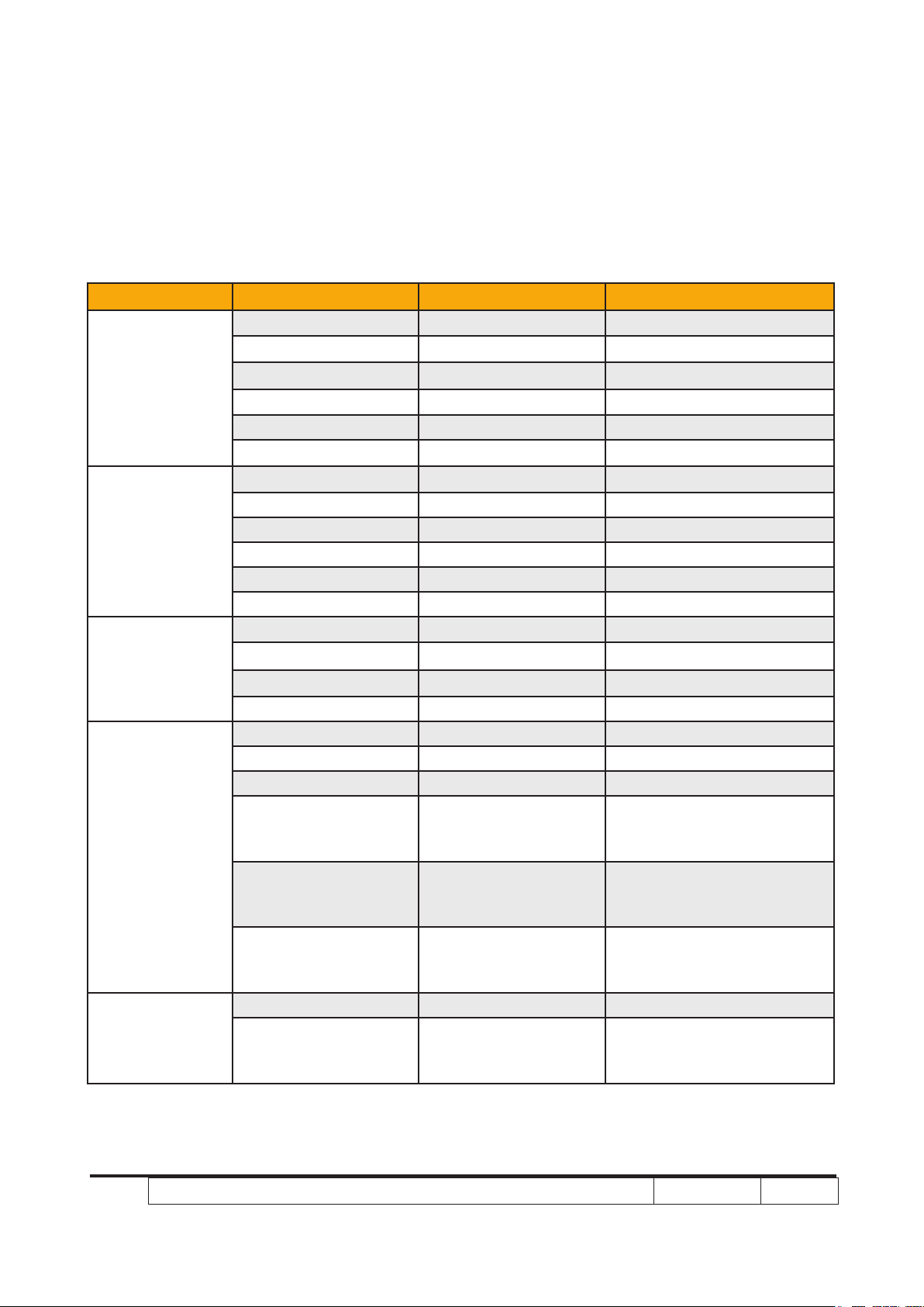
3-2 Main Procedure
No Symptom
1 No Power
2 Auto Shut Down
Procedure
- Ensure the Power Cord and AC Power Outlet are securely
connected
- Check Lamp Cover and Interrupt Switch
- Ensure all connectors are securely connected and aren’t
broken
- Check Lamp Driver
- Check LVPS
- Check Main Board
- Check Power LED status
a. Quick Flashing RED and Steady BLUE by returns
- Check Fan
b. Quick Flashing BLUE and Steady RED by returns
- Check Lamp
- Check Lamp driver
c. Color Wheel
- Check Color Wheel
- Check Photo Sensor
- Ensure the Signal Cable and Source work
(If you connect multiple sources at the same time, use the
“Source” button swtich)
- Ensure all connectors are securely connected and aren’t broken
3 No Image
- Check Main Board
- Check DMD Board
- Check Color Wheel
- Check DMD Chip
- Check Engine Module
Page 55

X1160 Series/X1260 Series/X1160Z Series/X1260K Refresh
Condential
3-3
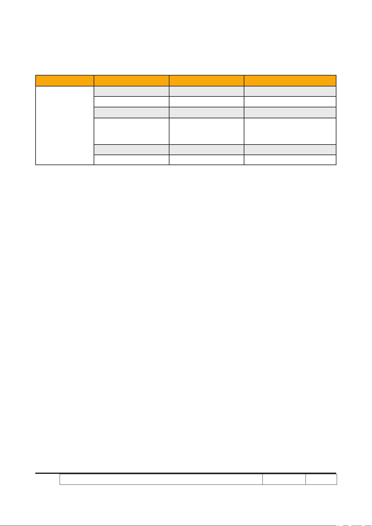
No Symptom
4 No Light On
5
Machanical Noise
Procedure
- Ensure all connectors are securely connected and aren’t broken
- Check Lamp Module
- Check Lamp Driver
- Check LVPS
- Check Main Board
- Check Color Wheel
- Check Fan Module
- Check if the Main Board and the DMD Board are
assembled properly
6 Line Bar/Line Defect
7 Image Flicker
8 Color Abnormal
- Check Main Board
- Check DMD Board
- Check DMD Chip
- Do “Reset(All data)” of the OSD Menu
- Ensure that the signal cables and source are work as well
- Check Lamp Module
- Check Color Wheel
- Check DMD Board
- Check Main Board
- Do “Reset(All data)” of the OSD Menu
- Adjust Color Wheel Index
- Check Main Board
- Check DMD Board
- Check Color Wheel
Page 56

X1160 Series/X1260 Series/X1160Z Series/X1260K Refresh
Condential
3-4
No Symptom
9
Poor Uniformity/
Shadow
Procedure
- Ensure the projection screen without dirt
- Ensure the projection lens is clean
- Ensure the Brightness is within spec
- Check rod alignment
- Check Engine Module
- Ensure the projection screen without dirt
10
11 Garbage Image
12
13 Function Abnormal
Dead Pixel/Dust
(Out of spec.)
Remote Control/
Control Panel Failed
- Ensure the projection lens is clean
- Clean DMD Chip and Engine Module
- Check DMD Chip- Check Engine Module
- Ensure that the signal cables and source work as well
- Check Main Board
- Check DMD Board
- Remote Control
a.Check Battery
b.Check Remote Controller
c.IR receiver
d.Check Main Board
e.Check IR Board (for refresh models)
- Control Panel
a.Check Power Key
b.Check Main Board
- Do “Reset(All data)” of the OSD Menu
- Check Main Board
- Check DMD Board
Page 57

X1160 Series/X1260 Series/X1160Z Series/X1260K Refresh
Condential
3-5
No Symptom
Forgetting Password
14
(adminstrator Password)
Procedure
- An unique Universal Password which is printed on the
Security Card. This unique password is a back door of
Administrator Password which will be accepted by projec tor anytime no matter what the Administrator Password is.
- How to get the Universal Password?
(1) Click the “AcerSNID”
(2) Input SNID number.(SNID number is on the Security
Card)
(3) Click“Calculate”.Then the Universal Password will ap
-pear.
Page 58

3-3 Beep Sound
Power on (as soon as power button
pressed)
Power on (lamp lighting failed) 2 x {So(0.1s) – Off(0.1s)} per lighting failure
Power on (lens cap was not opened, for
the model with sliding lens cover only)
Close lens cap while projector is operating (for the model with sliding lens cover
only)
Power off (power button pressed twice) So(0.3s)
Fan lock So(0.1s) periodically per second
Overheat 2 x {So(0.1s) – Off(0.1s)} periodically per sec-
Lamp error 3 x {So(0.1s) – Off(0.1s)} periodically per sec-
Lamp Life reminding 3 x {Do(0.2s) – Off(0.8s) – So(0.2s) –
Presentation Timer (time is up) 3 x {Do(0.1s) – Off(0.9s)} - So(0.5s)
So(0.3s)
12s interval for each trial lighting. Max 4 times
of trial
2 x {So(0.1s) – Off(0.1s)} periodically per 3
seconds, Totally 5 cycles. Turn off projector
after 5 cycles.
2 x {So(0.1s) – Off(0.1s)} periodically per 3
seconds, Totally 5 cycles. Turn off projector
after 5 cycles.
ond
ond
Off(0.8s)} with reminding message
X1160 Series/X1260 Series/X1160Z Series/X1260K Refresh
Condential
3-6
Page 59

Chapter 4
Function Test & Alignment Procedure
4-1 Test Equipment Needed
- IBM PC with SVGA/XGA resolution
- DVD player with Multi-system (NTSC/PAL/SECAM), equipped “Component”, “S-Video”
, “Composite” and "HDMI".
- HDTV Source (480P, 720P, 1080i)
- Minolta CL-100
- Quantum Data 802B or CHROMA2327 (Color Video Signal & Pattern Generator)
- After changing parts, check the information below.
4-2 Service Mode
1. Turn on the projector and input the signal
2. Do the following actions sequentially to enter service mode menu
(1) Press "Power> Left>Left>Menu".
(2) Service mode will be shown.
(3) After conrming the conguration, press "Exit" to exit.
4-3 OSD Reset
1. After nal QC step, we have to erase all saved change again and resotre the OSD
default setting. The following actions will allow you to erase all end-users' settings and
restore the default setting:
(1) Please enter OSD menu.
(2) To execute "Reset" function.
X1160 Series/X1260 Series/X1160Z Series/X1260K Refresh Condential
4-1
Page 60

X1160 Series/X1260 Series/X1160Z Series/X1260K Refresh Condential
4-2
4-4 Test Condition
- Circumstance brightness: Dark room less than 5.0 lux.
- Inspection distance: 1.8m~2.5m functional inspection.
- Screen size: 60 inches diagonal
- After repairing each X1160/X1260/X1160 Refresh/X1260 Refresh/X1160Z/X1160Z
Refresh/X1260K Refresh, the unit should be run-in (refer to the table below)
Symptom Run-in Time
Normal repair 2 hours
NFF 4 hours
Auto shutdown 6 hours
- Enter Burn-In Mode
* Cycle setting is based on the defect symptoms. ie: If it is NFF, the run-in time is 4 hours. You have
to set the lamp on for 50 min. and lamp off for 10 min for 4 cycles.
Press power > left > left > Menu
Choose Burn-In Test > enter
Lamp On (Min) Press right key to adjust the time (50)
Lamp Off (Min) Press right key to adjust the time (10)
Set burn in cycle Press right key to adjust the cycle
After setting up the time, choose Burn-In mode and hit enter
Screen Defects (While replacing DMD Chip, DMD Board and Main Board)
Page 61

X1160 Series/X1260 Series/X1160Z Series/X1260K Refresh Condential
4-3
4-5 Test Inspection Procedure
Change parts/
Update
Version Update v v v
Color Wheel Index v v
PC
Calibration
Video
Calibration
Reset lamp hour v
OSD Reset v v
EDID v
Re-write Lamp
Hour Usage
Reset Default
Language (for
refresh models)
Rod Adjust v
Waveform
Download (for
refresh models)
M/B FW
v v
v v
v
v v v
v v v
Color
Wheel
Lamp
Module
Engine EDID
Lamp
Driver
4-6 PC MODE
NOTE:Test Signal:analog 800 x600@60Hz(X1160 Refresh/X1160/X1160Z
Refresh/X1160Z),analog1024x768@60Hz(X1260 Refresh/X1260/X1260K
Refresh).Take X1260 for example.
1. Frequency and tracking boundry
Procedure - Test equipment: video generator.
- Test signal: analog 1024 x 768@60Hz
- Test Pattern: general-1 or master
- Check if the image sharpness is well-performed.
General-1
Master
Page 62

X1160 Series/X1260 Series/X1160Z Series/X1260K Refresh Condential
4-4
- If not re-adjust by the following steps:
(1) Select "Frequency" function to adjust the
total pixel number of pixel clock in one line
period.
(2) Select "Tracking" function and use right or
left arrow key to adjust the value to minimize
video icker.
- Adjust Resync or Frequency/Tracking/H.
Position/V. Position to the inner screen.
Inspection item - Eliminate visul wavy noise by Rsync, Frequency
or Tracking selction.
- Check if there is noise on the screen.
- Horizontal and vertical position of the vedio
should be adjustable to the screen frame.
Criteria - If there is noise on the screen, the product is
considered as faliure product.
- If there is noise on the screen, use auto or
manul “frequency” function or “tracking” function
to adjust the screen.
- The PC mode functionally sure be workable
include support format with frequency and auto
detected functional will be workable.
2. Light Leak
Procedure - Test equipment: video generator.
- Test signal: analog 1024x768@60Hz
- Test Pattern: gray 10 patterns
- Check if the light leaks.
* Light leak on reective edge, eyecatcher, bond-
wires and exposed metal.
Inspection item - Light leak check.
- Bright blemish (dirty).
Criteria - The bright blemish is unacceptable when it is
more than four under gray 10 pattern
- Ref. below table
Note: The defect criteria follows TI specication.
3. Blemish (Dark)
Gray 10
Blue 60
Page 63

X1160 Series/X1260 Series/X1160Z Series/X1260K Refresh Condential
4-5
Procedure - Test equipment: video generator.
- Test signal: analog 1024x768@60Hz.
- Test Pattern: blue 60
Inspection item - Dark blemish check.(dirty)
Criteria -The dark blemish is unacceptable when it is
more than four under blue 60 pattern
- Ref. below table
Note: The defect criteria follows TI specication.
4. Dead Pixel (Bright pixel)
Procedure - Test equipment: video generator.
- Test signal: analog 1024x768@60Hz.
- Test Pattern: full black
Inspection item - Bright pixel check.
Note: Frame dimension under operative zone1
inch
Criteria - Bright pixel is unacceptable.
- Ref. below table
Note: The defect criteria follows TI specication.
Full black
5. Dead Pixel (Dark pixel)
Procedure - Test equipment: video generator.
- Test signal: analog 1024x768@60Hz.
- Test Pattern: full white
Inspection item - Dead pixels check.
- White pattern (IRE=100)
- Adjacent dark pixel.
Criteria - The number of the dead pixels should be less or
equal to 6 pixels.
- Adjacent pixel with each other is unacceptable.
Full white
Page 64

X1160 Series/X1260 Series/X1160Z Series/X1260K Refresh Condential
4-6
- Ref. below table
Note: The defect criteria follows TI specication.
6. Focus test
Procedure - Test equipment: video generator.
- Test signal: analog 1024 x 768@60Hz
- Test Pattern: full screen or MEME Sony
Inspection item - Focus check
Criteria - From screen 1.5 M via visual to check the focus,
look at the entire screen, focus shall be clear,
crisp, and sharp over the entire surface of the
display pattern. (Blur word on one of the corner
after adjustment is acceptable. However, the
word should at least be recognizable.)
7. Color performance
Procedure - Test equipment: video generator.
- Test signal: DVI (HDMI) 720p,1080i
- Test Pattern: Master, In focus II or SMPTE RP-
133
* Please refer to 4-2 to enter service mode.
Use 720P & 1080i signal, master pattern to do
HDTV test. Color cannot discolor to purple and
blue. If the test result is discoloration or ickering, please return the unit back to repair centers.
Inspection item - Check if each color level is well-functioned.
- color saturations
Full screen
MEME Sony
Master
InFocus II
/ 64 gray RGBW
Criteria - Screen appears normal. It should not have any
abnormal condition, such as lines appear on the
screen and so on.
- Color appears normal.
- It is acceptable to have few lines ashing at the
center and on the edge of 1080i image. However, rest of the image should appears stable.
- RGBW should all appear normal on the screen
and sort from R -G-B-W.
- Color levels should be sufcient and normal.
SMPTE RP-133
Page 65

X1160 Series/X1260 Series/X1160Z Series/X1260K Refresh Condential
4-7
(the unidentied color levels on both left and
right sides should not over 8 color levels.)
- Grey level should not have abnormal color or
heavy lines.
- The PC mode functionally sure be workable
include support format with frequency and auto
detected functional will be workable
4-7 Calibration
1. YPbPr calibration
Procedure - Test equipment: video generator.
- Once main board is changed, YPbPr calibration
should be done as well.
(1) Test signal: 480P
(2) Test Pattern: SMPTE BAR
- Note
(1) Calibration pattern should be in ll screen
mode.
(2) Please refer to 4-2 Guide to Entering Service
Mode and OSD Reset.
(3) Choose and access YPbPr Calibration for
correction in service mode. Choose “menu”
to leave the service mode after all.
SMPTE BAR
In focus II / 64 Gray
RGBW
Check pattern - Test signal: 480P
- Test pattern: In focus II or 64 grey RGBW
* After nishing ADC adjustment, check 64 gray
RGBW pattern.
Inspection item - Color sturations
Page 66

X1160 Series/X1260 Series/X1160Z Series/X1260K Refresh Condential
4-8
Criteria - There should not have any lack of RGBW. The
color should appear normal and sort in right
order.
- Color levels should be sufcient and normal.
(the unidentied color levels on both left and
right sides should not over 8 color levels.)
- Grey level should not have abnormal color or
heavy lines.
2. PC calibration
Procedure - Test equipment: video generator
- Once main board is changed, PC calibration
should be done as well.
(1) Test signal analog: 1024x768@60Hz
(2) Test Pattern: White(up) Black(down)
- Note
(1) Caibration pattern should be in ll screen
mode.
(2) Please refer to 4-2 Guide to Entering Service
Mode and OSD Reset.
(3) Choose and access PC Calibration for cor-
rection in service mode. Choose “menu” to
leave the service mode after all.
White / Black
Check pattern - Test signal: analog 1024 x 768@60Hz
- Test pattern: In focus II or 64 grey RGBW
* After nishing ADC adjustment, check 64 gray
RGBW pattern.
Inspection item - Color sturations
Criteria - There should not have any lack of RGBW. The
color should appear normal and sort in right
order.
- Color levels should be sufcient and normal.
(the unidentied color levels on both left and
In focus 2 / 64 gray
RGBW
Page 67

X1160 Series/X1260 Series/X1160Z Series/X1260K Refresh Condential
4-9
right sides should not over 8 color levels.)
- Grey level should not have abnormal color ot
heavy lines.
Defect specication table
Order Symptom Pattern Criteria
Black pattern
1 Bright pixel ( dots)
( IRE=O)
2 Dark pixel(dots) White pattern
3 Unstable pixel (dots) Any pattern
A+B=0
A+B=6
A+B=1
4
5 Dark blemish (Dirty) Blue 60 pattern
6 Bright blemish (Dirty) Gary 10 pattern
7 Bright dot on frame Black pattern 2
Adjacent dark pixel
(dots)
Any pattern
A+B=0
A+B=4
(diameter <1/2 inch)
A+B=4
(diameter <1/2 inch)
4-8 Video Performance
1. CVBS
Procedure - Test equipment: DVD player
- Test signal: CVBS
Inspection item - Video performance test
Inspection Distance - 1.8M ~2.5M
Criteria - Check any abnoraml color, line distortion or any
noise on the screen.
Motion video
Page 68

X1160 Series/X1260 Series/X1160Z Series/X1260K Refresh Condential
4-10
- Check the sound from speakers.(Only for
X1260 Refresh/X1260/X1260K Refresh)
2. S-Video
Procedure - Test equipment: DVD player
- Test signal: S-Video
Inspection item - Video performance test
Inspection Distance - 1.8M ~2.5M
Criteria - Check any abnoraml color, line distortion or any
noise on the screen.
- Check the sound from speakers. (Only for
X1260 Refresh/X1260/X1260K Refresh)
3. HDTV/ Component
Procedure - Test equipment: DVD player
- Test signal: Ycbcr/YPbPr
Inspection item - HDTV performance test
Inspection Distance - 1.8M ~2.5M
Criteria - Check any abnoraml color, line distortion or any
noise on the screen.
- Check the sound from speakers. (Only for
X1260 Refresh/X1260/X1260K Refresh)
4. Audio Test (Only for X1260 Refresh/X1260/X1260K Refresh)
Procedure - Test equipment: DVD player
- Test signal: CVBS
Inspection item - Audio performance test
Inspection Distance - 1.8M ~2.5M
Criteria - Check the sound from speakers.
- Check “Volume” is normal
- Check “Mute” is normal
Page 69

X1160 Series/X1260 Series/X1160Z Series/X1260K Refresh Condential
4-11
4-9 Optical Performance Measure
Inspection Condition
- Environment luminance: 5 Lux
- Product must be warmed up for 3 minutes
- Distances from the screen: <Max. zoom & 60 inches diagonal> 1.8 M
- Screen Size: 60 inches diagonal
- Reset to default before measurement
1. Test equipment
Procedure - Test equipment: video generator.
- Test signal: analog 1024x768@60Hz.
2. Brightness
Procedure - Full white pattern
- Use CL100 to measure brightness values of
P1~P13.
- Follow the brightness formula to calculate
brightness values.
☼ Brightness Formula
Avg.(P1~ P9)x1.1m2
Criteria -800 lumens (for X1160/X1260/X1160Z)
-900 lumens (for X1160 refresh/X1260 refresh/
X1160Z refresh/X1260K refresh)
Full white pattern
Full black pattern
Page 70

X1160 Series/X1260 Series/X1160Z Series/X1260K Refresh Condential
4-12
3. Ful On/Full Off Contrast
Procedure - Full white pattern & full black pattern
- Use CL100 to measure brightness values of full
white pattern P5 & full black pattern B5 ( see im-
age: full white)
- Follow Contrast formula to calculate contrast
values.
☼ Contrast Formula
P5/B5
note: P5=center of white image
B5 = the center of black image.
Criteria - 1500:1 (X1160/X1260/X1160Z)
- 1400:1 (X1160 Refresh/X1260 Refresh/
X1160Z Refresh)
- 400:1 (only for X1260K Refresh)
4. Uniformity
Procedure - Full white pattern
- Use CL100 to measure brightness values of
P1~P13 (see image: full white).
- Follow the Uniformity formula to calculate
average values.
ANSI Uniformity = Avg. (P1, P3, P7, P9)/P5X100%
Criteria - 65 %
4-10 Others
1. Functional Inspection
Page 71

X1160 Series/X1260 Series/X1160Z Series/X1260K Refresh Condential
4-13
Keypad button - All keypad buttons must operate smoothly.
General - All OSD functions must be checked for functionality.
When OSD menu is displayed, there shall be no vis-
ible peaking, ringing, streaking, or smearing artifacts
on the screen.
Factory Default - The factory settings (with appropriate centering, size,
geometry distortion, etc.) shall be displayed
upon “Recall” is selected from OSD
Display Size - All preset modes shall expand to fullscreen size using OSD
Horizontal and Vertical Size controls-
Display Data Channel - The purpose of the DDC test is to ver
(DDC) the DDC1/DDC2B operation of the projec
and to verify Plug & Play function.
Acoustic - High pitch sound from cooling fan and color wheel unacceptable.
tor
Check item Check point
Text & Pattern
Exterior
missing letters & pattern or blurry prints are
unacceptable.
dirt, scrape, water ripples and uneven color
are unacceptable.
Buttons stuck buttons are unacceptable.
Focus ring Focus ring is functioning smoothly.
Logo
Screw
missing logo, missing prints and blurry prints
are unacceptable
All screw sure be xed and in right type.
Page 72

Chapter 5
Firmware Upgrade
5-1 Equipment Needed
Software : (DDP 2230- USB)
- DLP Composer
- Firmware
- Library le (library le has to put in PC and set right path in step of 5-4-4 Firmware
Upgrade Procedure)
Hardware :
- Projector
- Power cord (42.53506G002)
- USB Cable (42.87304G001)
- PC or Laptop
X1160 Series/x1260 Series/X1160Z Series/X1260K Refresh
Condential 5-1
Page 73

X1160 Series/x1260 Series/X1160Z Series/X1260K Refresh Condential
5-2
5-2 DLP Composer Lite Setup
Procedure
1. Choose “DLP Composer Lite V7.1 Setup”
Program.
2. Click “Next” buttom.
3. Read “License Agreement”.
- Choose “I accept and agree to be bound
by all the terms and conditions of this
License Agreement”.
4. Click “Next”.
5. Click “Next”.
3
4
Page 74

X1160 Series/x1260 Series/X1160Z Series/X1260K Refresh Condential
5-3
6. Click “Next”.
7. Click “Next”.
8. Writing system registry values.
9. Click “Finish”.
Page 75

X1160 Series/x1260 Series/X1160Z Series/X1260K Refresh Condential
5-4
5-3 USB Driver Upgrade
Procedure
1. set up
- Plug in Power cord to projector.
- Link PC USB port and projector USB port
by USB Cable.
2. Execute Program
(1) “Found new hardware wiszard” will be
(2)
appearred on the screen.
(2) Select “Install the software automatically
(Recommended)”.
(3) Then click “Next”.
3. Finish
- Click “Finish” to end the installation.
(3)
Page 76

X1160 Series/x1260 Series/X1160Z Series/X1260K Refresh Condential
5-5
5-4 Firm Upgrade Procedure
- Take X1160 for example,X1260/X1160 Refresh/
X1260 Refresh/X1160Z/X1160Z Refresh/
X1260K Refresh is the same as X1160
1.
Set-up
- Hold on “Power” and plug in power cord
while holding on “Power”.
- Once the power LED lights on Blue&Red
at the same time, plug in USB cable into
the projector and link to the USB port of a
PC.
Note: The system fan and the light will not
operated.
2. Execute the “DLP Compose
TM”
le.
.
3. Click “edit” and “perferences”.
4. Click “Library”.
- The library path located in the default
installation directory.
- E:\ Program Files\DLP Composer Lite 7.1\
library v7.1 0330.
Note: If not, press “Browse” to select the right
path.
Page 77

X1160 Series/x1260 Series/X1160Z Series/X1260K Refresh Condential
5-6
5. Select “Edit\preferences\Communications”
- choose “USB.” Click “OK”.
6.
Choose “Flash Loader”.
- Click “Browse” to search the rmware le.
(X1160/X1160 Refresh).
7. Selete the item “skip Boot Loader Area”
(select 16KB).
- Click “Reset Bus” to erase the ash
memory.
8. If the rmware is ready, click “start
download” to process the rmware
upgrade.
- Click “Yes” to erase the ash memory.
X1160-A03-07091754.img
X1160
X1160
Page 78

X1160 Series/x1260 Series/X1160Z Series/X1260K Refresh Condential
5-7
9. When rmware upgrade process is
nished, the unit return to stand-by status
The LED power lights on and appears Red.
-Unplug USB cable and power cord and
replug in power cable.
10.Restart the unit and enter the service
mode to check the rmware version.
(To enter service mode, please refer to
Chapter 4 Funcation Test and Alignment
Procedure.)
Page 79

5-5 Waveform Download (for refresh models)
(1) Hold on “Power“ button then plug in the Power Cord
Note: At this moment ,Power LED ash in blue and red about 2 seconds until Power
LED ash in blue only for 2 seconds, please release the power botton
(2) After ashing, LED is in steady condition and you can judge the actions as the
following table:
Power LED status Result
Red OK
Blue + Red (It will light on red
only after 10 seconds) Fail
X1160 Series/x1260 Series/X1160Z Series/X1260K Refresh Condential
5-8
Page 80

Chapter 6
EDID Upgrade
6-1 EDID Introduction
Extended Display Identication Data is a VESA standard data format that contains basic
information about a display device and its capabilities, including vendor information,
maximum image size, color characteristics, factory pre-set timings, frequency range limits,
and character strings for the monitor name and serial number.
The information is stored in the display and is used to communicate with the system
through a Display Data Channel (DDC), which sites between the display device and the
PC graphics adapter. The system uses this information for conguration purposes, so the
monitor and system can work together.
Note: If a display device has digital input ports, like DVI or HDMI, but without EDID in its
main board, the display device will show no image while the input source is digital signal.
After EDID upfraded, do" default language reset"
X1160 Series/x1260 Series/X1160Z Series/X1260K Refresh Condential
6-1
Page 81

6-2 Equipment Needed
Software
- EDID Program (Generic V0.51)
- EDID File *.ini
Hardware
- Projector
- Generic Fixture (80.58704.001) for EDID Key-in (Fixture: JP3 must be closed)
- Power cord(42.53506G002)
- RS-232 Cable (pin to pin, F-M)
- Monitor
- PC
- VGA cable(42.00201G001)
- Power adapter for xture (47.57702G001)
X1160 Series/x1260 Series/X1160Z Series/X1260K Refresh Condential
6-2
Page 82

6-3 Setup Procedure
To Analog Port
RS232 Cable
1. Connect all ports
- Power adapter to xture JP1
- Fixture P1 to PC COM1 Port
- Fixture P2 to Projector analog port
6-4 EDID Key-In Procedure
- Take X1160 for example,X1260 /X1160 Refresh /
X1260 Refresh/X1160Z/X1160Z Refresh/X1260K
Refresh is the same as X1160
1. Click on "EDID" to execute EDID program
2. Choose model
P2
P1
JP1
Adapter
(1) In the port selection bar, please choose
the port that you use. ie: if you use
"COM1", choose COM1 in the port
selection.
(2) Click on "Model".
(3) Choose the EDID that responses to the
model that you choose.
(2)
(1)
(3)
X1160 Series/x1260 Series/X1160Z Series/X1260K Refresh Condential
6-3
Page 83

X1160 Series/x1260 Series/X1160Z Series/X1260K Refresh Condential
6-4
3. Programming
(1)
(3)
(1) Key in the serial number into the
barcode blank space.
(2) In "Write Source Select" make a check
in "Analog".
(3) Click "Program".
4. Change the cable to Analog
- Message box appears on the screen,
then click "OK".
5. When the EDID program for VGA is
completed, a message "OK" will appear on
the screen.
(2)
6. (1)In the Read item,select “Analog” and
“Trans”.
(2)Please press “Read” button.
7. EDID Informations will show the result.
(2)
(1)
Page 84

X1160 Series/x1260 Series/X1160Z Series/X1260K Refresh Condential
6-5
6-5 Default Language Reset (for refresh models)
(1) Hold on “Power“ button then plug in the Power Cord
Note: At this moment ,Power LED ash in blue and red about 2 seconds until Power
LED ash in blue only for 2 seconds, please release the power botton
(2) After ashing, LED is in steady condition and you can judge the actions as the
following table:
Power LED status Result
Red OK
Blue + Red (It will light
on red only after 10 seconds)
Note: if fail, please do the actions as above steps item (1)-(2)
S/N General rule :
Fail
Use the last 1 digit code (as red word) for language information
Language Code (F) Default Language
1 English
2 Thailand
3 Japan
4 TC
5 SC
6 Russian
7 Germany
8 Hungarian
Page 85

Appendix A
Assy Lamp Module X1160
X1160 Series/X1260 Series/X1160Z Series/X1260K Refresh Condential
I
Page 86

X1160 Series/X1260 Series/X1160Z Series/X1260K Refresh Condential II
item P/N Rev Description Parts Supply
1 52.83F12G001 A LAMP RUBBER HD72
2 61.80L06G001 A UVIR SPRING PLATE SUS301 80L
3 52.85902G012 A LAMP CONTACT COVER RUBBER 300C
4 85.1A326G050 A SCREW PAN HEAD MECH M2.6*5 BLACK
5 61.00061G001 A LOCK SCREW PAN MECH M3*8.5-3.5 Ni
6 51.88T12G001 A LAMP BOTTOM X1160
7 23.88T15G001 A OSRAM P-VIP 150-180/1.0 E20.6
8 61.88T01G001 A LAMP HOLDE OSRAM E206 X1160
9 61.88T10G001 A LAMP LIGHT CUT AL X1160
10 61.88T11G001 A LAMP LEFT MESH X1160
11 23.87M10G001 A UV-IR 24*25*2mm(5*5mm cut)UNAXIS
12 61.86808G001 A LAMP CHANGER HANDLE SUS DP725
13 61.83F12G001 A LAMP CLAMP SUS301 t=0.3 HD72
14 61.83M17G001 B LAMP LIGHT CUT 2400MP
15 76.83M02G002 A OUTSIDE W.A. 85/95mm FOR 2400MP
Page 87

X1160 Series/X1260 Series/X1160Z Series/X1260K Refresh Condential III
ASSY MAIN-BD MODULE X1160
item P/N Rev Description Parts Supply
1 51.88T04G001 A IO COVER X1160
2 61.88T16G001 A SHIELDING MAIN-BD X1160
3 80.88T01G001 A03 PCBA MAIN BOARD FOR X1160
4 85.005AGG075 A SCREW HEX I/O #4-40*H5*L7.5 Ni NYLOK
5 85.1A123G060 A SCREW PAN MECH M3*6 NI
6 41.88T02G001 A EMI GASKET L180*W4*H1
7 41.82G03G001 A EMI GASKET USB CONNECTOR EP719
8 86.0A123G024 A HEX NUT M3*0.5P L2.4 Ni
Page 88

X1160 Series/X1260 Series/X1160Z Series/X1260K Refresh Condential IV
ASSY ENGINE MODULE X1160
Page 89

X1160 Series/X1260 Series/X1160Z Series/X1260K Refresh Condential V
item P/N Rev Description Parts
Supply
1 51.88T09G001 A FOCUS RING X1160
2 85.WA321G050 A SCREW PAN HEAD M1.7*5 BLACK ‘’
3 85.1A126G060 A SCREW PAN MECH M2.6*6 Ni
4 23.88T01G001 A YO PROJECTION LENS YM09XS FOR X14
5 52.89F01G001 A PROJECTION LENS RUBBER HD65
70.88T11GR11 ASSY NEW COLOR WHEEL MODULE X1 V
6 70.88T08G001 A ASSY COLOR WHEEL MODULE X1160 V
7 61.88N13G001 A ROD COVER SUS301,X15
8 61.88N14G001 A ROD HOLDER SUS301,X15
9 23.88N17G001 A YO INTEGRATING ROD FOR x15
10 61.88N12G001 A ROD SPRING SUS301,X15
11 70.88T07G001 A ASSY ENGINE BOTTOM MODULE X1160
12 23.88N20G001 A YO CONDENSER1 FOR X15
13 23.88N20G011 A YO CONDENSER2 FOR X15
14 23.88N06G002 A PRODISC X15 PLASTIC RELAY LENS
15 41.85W05G001 A EMI GASKET W8*H8*L45
16 85.4A826G118 A STEP SCREW FOR TYPEX DMD M2.6*11.8mm,X15 V
17 61.88N03G001 A DMD HEAT SINK AL1070,X15
18 52.88N03G001 A HEAT SINK RUBBER,X15
19 80.88T02G001 A03 PCBA DMD BOARD FOR XD1130
20 52.87J01G001 A
21 48.87K01G001 A DMD Type-X 800x600 PIXEL 0.55” SVGA LVDS “TI” V
22 61.88N15G001 A DMD MASK SUS301,X15
23 52.88N04G001 A DMD RUBBER,X15
24 61.88N01G001 A ENGINE BASE MG,X15
25 52.88N01G001 A OFF RAY RUBBER,X15
26 61.88N05G001 A OFF RAY PLATE AL5052,X15
27 87.FL030G008 A WASHER FLAT 7*3.1*0.8t PC PINGOOD WS-1M
DMD THERMAL PAD 25*17*0.5t FUJIPOLY
SARGON GR-Hn
V
Page 90

X1160 Series/X1260 Series/X1160Z Series/X1260K Refresh Condential VI
ASSY ENGINE BOTTOM MODULE X1160
item P/N Rev Description Parts Supply
1 51.88N01G001 A ENGINE BOTTOM COVER PC945,X15
2 23.88N02G001 A YO MIRROR1 FOR X15
3 61.88N11G001 A MIRROR SPRING SUS301,X15
4 52.88N05G001 A RELAY RUBBER,X15
5 52.85808G001 A PORON-LENS BLACK XB31
Page 91

X1160 Series/X1260 Series/X1160Z Series/X1260K Refresh Condential VII
ASSY HOUSING MODULE X1160
Page 92

X1160 Series/X1260 Series/X1160Z Series/X1260K Refresh Condential VIII
item P/N Rev Description Parts Supply
1 51.88T10G001 A MYLAR FOR LVPS X1160
2 51.88T14G001 A ROD DUCT X1160
3 86.00122G015 D1 NUT HEX M2.0*0.4P L15 Ni
4 61.88T03G001 A SHIELDING BOTTOM COVER X1160
5 51.88T02G001 A BOTTOM COVER X1160
6 70.83U20G001 A ASSY ADJUST FOOT MODULE TDP-T9
7 52.86801G001 A RUBBER FOOT REAR DP725
8 41.83C09G001 A EMI TAPE W20*L50
9 41.82B01G001 A EMI GASKET W13*H10.5*L30mm
10 85.1A123G050 A SCREW PAN MECH M3*5 Ni
Page 93

X1160 Series/X1260 Series/X1160Z Series/X1260K Refresh Condential IX
D.C. X1160
item P/N Rev Description Parts Supply
1 75.88T03G001 A ASSY TOP COVER X1160
2 70.88T01G001 A ASSY BOTTOM HOUSING MODULE X1160
3 85.1A323G080 A SCREW PAN MECH M3*8 BLACK “GREEN”
4 70.88T02G001 A ASSY LAMP MODULE X1160
5 51.88T05G001 A LAMP COVER X1160
6 61.00061G001 A LOCK SCREW PAN MECH M3*8.5-3.5 Ni
Page 94

X1160 Series/X1260 Series/X1160Z Series/X1260K Refresh Condential X
ASSY BOTTOM HOUSING MODULE X1160
Page 95

X1160 Series/X1260 Series/X1160Z Series/X1260K Refresh Condential XI
item P/N Rev Description Parts Supply
1 70.88T09G001 A ASSY HOUSING MODULE X1160
2 75.88T01G001 A ASSY LVPS MATRITEK 160W XD1130
3 61.88T09G001 A BRKT INLET X1160
4 85.1A123G060 A SCREW PAN MECH M3*6 NI
5 51.88T03G001 A FRONT COVER X1160 V
70.88T12GR01 ASSY ENGINE MODULE X1160(SERVI) V
6 70.88T05G001 A ASSY ENGINE MODULE X1160
7 70.88T03G001 A ASSYMAIN-BD MODULE X1160
8 70.88T06G001 A ASSY FAN SHIELDING X1160
9 85.1A326G060 A SCREW PAN HEAD MECH M2.6*6 BLACK
10 70.88T04G001 A ASSY LAMP DRIVER MODULE X1160
11 61.88T02G001 A SHELDING TOP COVET X1160
12 41.85A01G001 A EMI GASKET / 10*27*20
13 41.88T01G001 A EMI q L85*W20
14 42.00454G001 A W.A 8P 120mm MB TO LVPS X1160
15 85.1C224G050 A
SCREW PAN MECH M4*5 COLOR W/TOOTH
WASHER
Page 96

X1160 Series/X1260 Series/X1160Z Series/X1260K Refresh Condential XII
ASSY LAMP DRIVER MODULE X1160
Page 97

X1160 Series/X1260 Series/X1160Z Series/X1260K Refresh Condential XIII
item P/N Rev Description Parts Supply
1 51.88T11G001 A HOLDER LAMP DRIVER X1160
2 75.88T02G001 A ASSY OSRAM LAMP DRIVER 160W(O6 MIC)
3 85.1A123G060 A SCREW PAN MECH M3*6 NI
4 85.3A122G040 A SCREW CAP MECH M2*4 Ni
5 42.00422G001 A W.A 5P 150mm LAMP DRIVER TO MB X1160 V
6 42.81G01G001 A
7 42.85F01G001 A
8 75.88T05G001 A
9 51.88N25G001 A
CABLE W. A . 2P #2 0 160mm L A P S TO
BALLAST PD120
CABLE W.A. 2P #22 160mm LAMP DRIVER
TO LAMP EP1690
A S S Y INTER R U P T SWI T C H MOD U L E
XD1130
I N T E R L O C K S W I T C H H O L D E R P C
MN3600H,EP721
V
V
Page 98

X1160 Series/X1260 Series/X1160Z Series/X1260K Refresh Condential XIV
ASSY FAN SHIELDING X1160
Page 99

X1160 Series/X1260 Series/X1160Z Series/X1260K Refresh Condential XV
item P/N Rev Description Parts Supply
1 85.1F123G260 A SCREW PAN MECH E/SF M3*26 Ni
2 49.88T01G001 A
3 43.88T01G001 A THERMAL SWITCH WITH BRACKET
4 85.1A123G060 A SCREW PAN MECH M3*6 NI
5 61.88T05G001 A SHIELDING ONE FAN X1160
6 41.83C09G001 A EMI TAPE W20*L50
7 51.88T13G001 A CAP ONE FAN DUCT X1160
8 61.88T12G001 A BODY ONE FAN DUCT X1160
SUNO N, KD E1207P KV1-A 70 *70*2 0 mm
AXIAL FAN
Page 100

X1160 Series/X1260 Series/X1160Z Series/X1260K Refresh Condential XVI
ASSY COLOR WHEEL MODULE X1160
 Loading...