

Page 1

& K DSWHU
System Board
The V35LA-N is an all-in-one Pentium-based system board that
features the comm on functions offered by a high-perform ance board,
as well as the multimedia functions. It has a power-management
function that conforms to the power-saving standards of the U.S,
Environmental Protection Agency (EPA) Energy Star program . It also
supports the Plug-and-Play feature.
The board utilizes a Pentium processor running at 75/50, 90/60,
100/66, 120/60, 133/66, 150/60, 166/66, or 200/66 MHz. It has one
riser card slot for future expansion. It also has four 72-pin SIMM
sockets that allow memory upgrade to a maximum of 128 MB, and
supports 256-KB/512-KB pipelined-burst second-level cache. The
onboard video controller, MPEG decoder, and audio controller enable
the system to offer both video and audio functions.
Standard features such as two serial ports, one parallel port, a diskette
drive interface, and an embedded hard disk interface are also
incorporated in the system board. A Universal Serial Bus (USB)
interface, video and audio connectors are added to the design to
enable the system to support additional peripherals.
The system is fully compatible with MS-DOS V6.X, OS/2, UNIX,
Windows NT and Windows 95 operating systems.
System Board 1-1
Page 2

1.1 System Board Layout
The system board has the following features and components:
Supports 3.3V Intel Pentium CPU (75/50, 90/60, 100/66, 120/60,
•
133/66, 150/60, 166/66 MHz, 200/66 MHz)
128-MB maximum system memory
•
Four 72-pin SIMM sockets that accept 4-, 8-, 16-, and 32-MB
•
SIMMs, with or without Extended Data Output (EDO) and Error
Checking and Correction (ECC) functions
256-KB or 512-KB pipelined-burst second-level cache
•
Integrates an enhanced PCI local bus IDE controller
•
Onboard video and graphics controller and 1- MB VGA memory,
•
upgradable to 2 MB
Audio controller compatible with Sound Blaster, Microsoft Sound,
•
and MPU-401
128-KB Flash ROM for system BIOS
•
One riser card slot
•
Dual 16C550 buffered serial ports and one ECP/EPP parallel port
•
USB interface that enables the system to support more
•
peripherals (optional)
Standard connector for Wavetable upgrade (optional)
•
PS/2 mouse and keyboard interface
•
Plug-and-Play function
•
Power-management function
•
Infrared function for cableless communication (optional)
•
Software shutdown circuitry (optional)
•
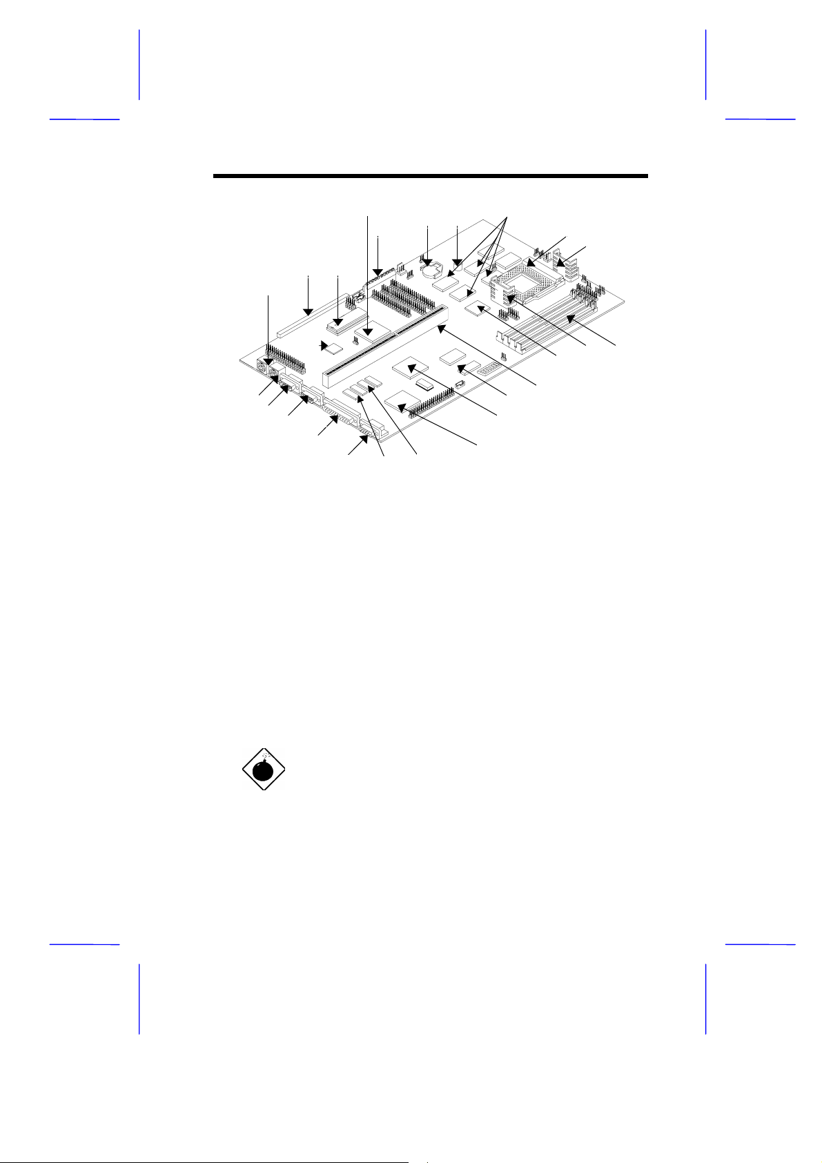
Figure 1-1 shows the board layout and the locations of the important
components.
1-2 User’s Guide
Page 3
1
2 3
4
5
6 7
8
9
10
25
24
23
22
21
20
1 PS/2 keyboard connector 14 Riser card slot
2 LSFM connector (optional) 15 PCI MPEG video decoder
3 BIOS 16 ASIC (PIIX3)
4 Ultra I/O controller 17 Video and graphics controller
5 Power connector 18 First 1-MB video DRAMs
6 Battery 19 Second 1-MB video DRAM sockets
7 Buzzer 20 VGA connector
8 Second-level pipelined-burst 21 Parallel port
cache
9 CPU socket 22 COM2 port
10 Voltage regulator with heatsink 23 COM1 port
11 SIMM sockets 24 PS/2 mouse connector
12 Voltage regulator with heatsink 25 Audio controller
13 ASIC (TXC)
19
18
15
16
17
13
14
1112
Figure 1-1 System Board Layout
The heatsink becomes very hot when the
system is on. NEVER touch the heatsink with
any metal or with your hands.
System Board 1-3
Page 4

1.2 ESD Precautions
Electrostatic discharge (ESD) can damage your processor, disk drives,
expansion boards, and other components. Always observe the
following precautions before you install a system component.
1. Do not remove a component from its protective packaging until
you are ready to install it.
2. W ear a wrist grounding strap and attach it to a metal part of the
system unit before handling components . If a wrist strap is not
available, maintain contact with the system unit throughout any
procedure requiring ESD protection.
1.3 Pre-installation Instructions
Always observe the following before you install a system component:
1. Turn off the system power and all the peripherals connected to
the unit before opening it.
2. Open the system according to the instructions in the housing
installation manual.
3. Follow the ESD precautions in section 1.2 before handling a
system component.
4. Remove any expansion boards or peripherals that block access
to the SIMM sockets or CPU socket.
5. See the following sections for specific instructions on the
component you wish to install.
Do not attempt the procedures described in
the following sections unless you are a
qualified service technician.
1-4 User’s Guide
Page 5
1.4 Installing a CPU
1.4.1 Installation Procedures
Observe the ESD precautions when installing
components. See section 1.2.
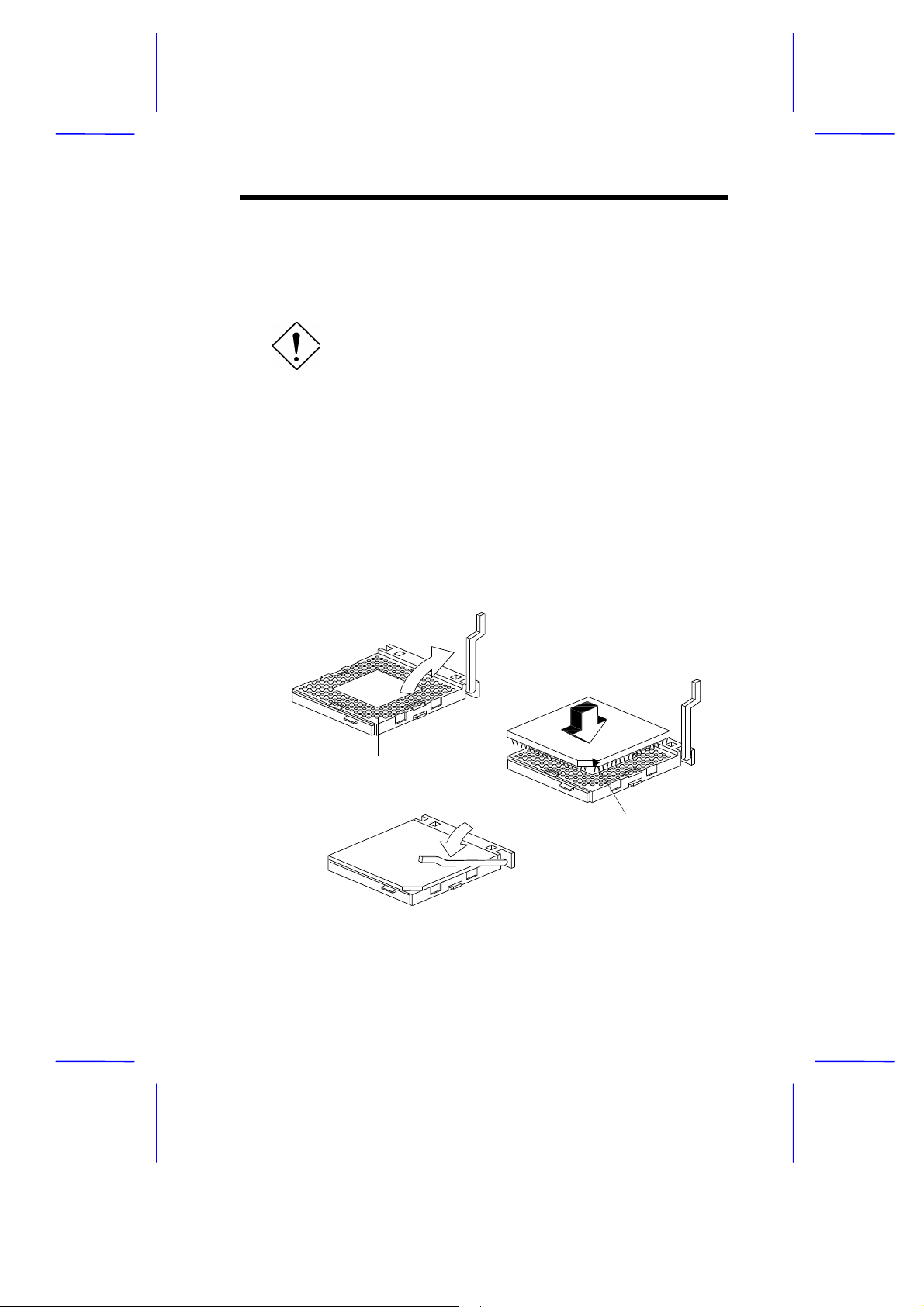
The system board features a zero-inser tion forc e (ZIF) sock et f or eas y
CPU installation.
Follow these steps to install a CPU:
1. Pull up the socket lever.
2. Insert the CPU, making sure that pin 1 (indicated by a notched
corner) of the CPU connects to hole 1 of the socket.
3. Pull down the socket lever to lock the CPU into the socket.
Step 1
Step 2
Hole for Pin 1
Step 3
Notched corner
Figure 1-2 Installing a CPU
System Board 1-5
Page 6
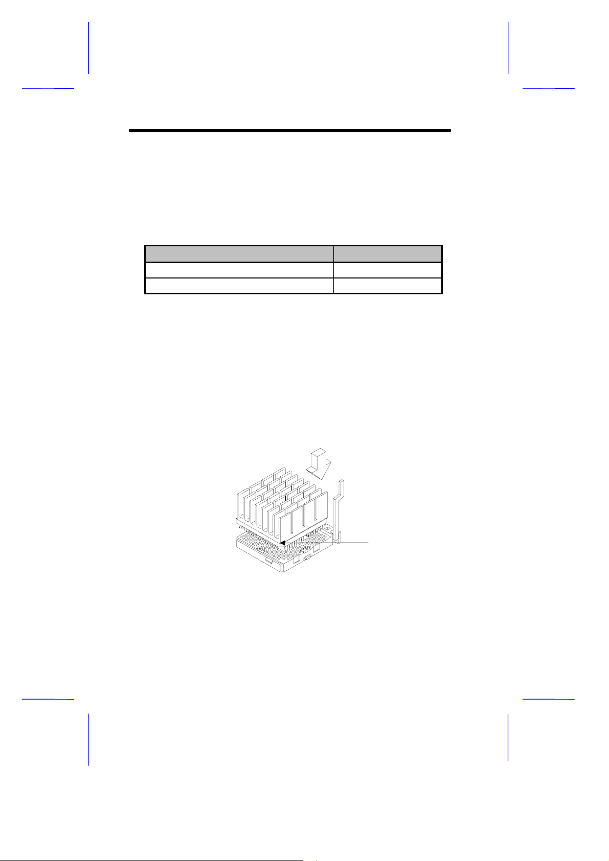
1.4.2 Installing an OverDrive CPU
The OverDrive CPU comes with a heatsink already mounted. To
maintain proper airflow around the CPU and heatsink, follow the
required clearances in Table 1-1.
Table 1-1 Clearances for OverDrive CPU and Heatsink
Location Minimum Clearance
Above the heatsink 0.4 inches
Sides of the CPU (at least 3 of 4) 0.2 inches
Follow these steps to install an OverDrive CPU:
1. Locate the CPU socket and pull up the socket lever.
2. Remove the old CPU carefully from the s ocket and place it in an
antistatic package.
3. Take the upgrade CPU out of its antistatic package.
4. Carefully insert the CPU into the sock et such that pin 1 (indicated
by a notched corner) of the CPU connects to hole 1 of the socket.
Notched Corner
Figure 1-3 Installing an OverDrive CPU
5. Push down the socket lever to lock the CPU into the socket.
1-6 User’s Guide
Page 7
See section 1.11 for the post-installation
instructions.
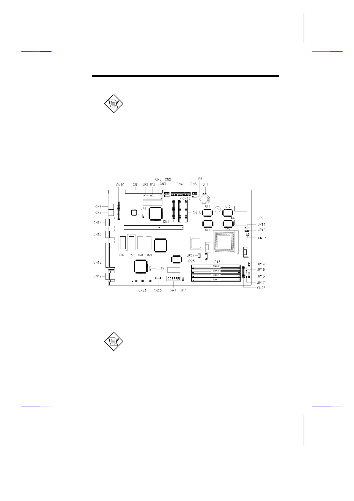
1.5 Jumpers and Connectors
Figure 1-4 shows the jumper and connector locations.
Figure 1-4 Jumper and Connector Locations
The shaded pin indicates pin 1.
System Board 1-7
Page 8

The following tables list the jumper settings and their corresponding
functions:
Table 1-2 System Board Jumper Settings
Jumper Setting Function
JP2
JP3 1-2
JP6 1-2
JP7 1-2 *
JP8, JP9 1-2 *
JP11 1-2 *
JP13 SHORT
JP14 1-2 *
JP16 1-2
JP19 1-2 *
*
1-2
2-3
2-3
OPEN *
2-3 *
2-3
2-3
2-3
OPEN
2-3
2-3
2-3
For BIOS ROM 28F001
Enable Boot Block Programming
Normal operation
Flash ROM (28F001)
EPROM
Block Flash EEPROM
Enable Acer BIOS logo
Enable OEM BIOS logo
Enable MPEG function
Disable MPEG function
Intel (1+4) burst sequence
Linear burst sequence
Enable SMM switch
Enable Reset switch
Assign one regulator for P54C CPU
Assign two regulators for P55C CPU
Enable P54C shutdown
Set P55C I/O voltage to 3.3V
Enable IDE and FDD LED
Enable IDE LED only
Enable onboard VGA
Disable onboard VGA
*
Default setting
1-8 User’s Guide
Page 9

Table 1-3 CPU Core Voltage Select
JP24 JP25 Vcore
OPEN
2-3
OPEN
3-4
1-2, 3-4
1-2 or 2-3 3.52V
3-4 2.9V
Table 1-4 Bus Frequency Select
SW1
1 2 Bus Frequency
ON ON 50 MHz
ON OFF 60 MHz
OFF ON 66 MHz
Table 1-5 CPU Core/Clock Ratio Select
SW1
3 4 P54C M1 K5
ON ON 5/2 1/1
OFF OFF 3/2 3/1 3/2
ON OFF 2/1 2/1 1/1
OFF ON 3/1 4/1
3.3V
2.7V
2.5V
Table 1-6 SB1/Password Function Select
SW1
5 6 Setting
Disable SB Bypass password ON
1
Sound Blaster
System Board 1-9
Page 10

Enable SB Check password OFF
1-10 User’s Guide
Page 11

Table 1-7 lists the onboard connectors.
Table 1-7 Onboard Connectors
Connector Function
CN1 LSFM interface (optional)
CN2 Fax/modem-in
CN3 CD audio in
CN4 Power connector
CN5 Standby control
CN6 Wavetable connector
CN7 USB/LAN connector
CN8 Keyboard connector
CN9 Mouse connector
CN10 Audio I/O connector
CN11 Diskette drive connector
CN12 IDE2 connector
CN13 IDE1 connector
CN14 COM1 port
CN15 COM2 port
CN16 IrDA connector
CN17 Fan power connector
CN18 Parallel port
CN19 VGA connector
CN20 Internal line-in connector
CN21 ATI Media channel (AMC) connector
CN23 FM-Towns connector (optional)
CN25 Power LED connector
JP10 Power on switch
JP15 IDE LED connector (for OEM)
JP17 IDE LED connector
System Board 1-11
Page 12

1.6 Installing Memory
The system mem ory is expandable to 128 MB by adding s ingle in-line
memory modules (SIMMs). See Figure 1-1 for the location of the
SIMM sockets. Section 1.6.1 tells how to install SIMMs.
The four 72-pin SIMM sockets on board acc ept single-density (4- and
8-MB) and double-density (16- and 32-MB) SIMMs, with or without
EDO and ECC functions, and with 70-ns or less DRAM s peed. The
ECC function enables the system to automatically detect and correct
data errors.
Table 1-8 lists the possible memory configurations.
Table 1-8 Memory Configurations
Bank 1 Bank 2 Total
SIMM 1 SIMM 2 SIMM 3 SIMM 4 Memory
4MB 4MB 8 MB
8 MB 8 MB 16 MB
16 MB 16 MB 32 MB
32 MB 32 MB 64 MB
4 MB 4 MB 8 MB
4 MB 4 MB 4 MB 4 MB 16 MB
4 MB 4 MB 8 MB 8 MB 24 MB
4 MB 4 MB 16 MB 16 MB 40 MB
4 MB 4 MB 32 MB 32 MB 72 MB
8 MB 8 MB 16 MB
8 MB 8 MB 4 MB 4 MB 24 MB
8 MB 8 MB 8 MB 8 MB 32 MB
8 MB 8 MB 16 MB 16 MB 40 MB
8 MB 8 MB 32 MB 32 MB 80 MB
1-12 User’s Guide
Page 13

Table 1-8 Memory Configurations (continued)
Bank 1 Bank 2 Total
SIMM 1 SIMM 2 SIMM 3 SIMM 4 Memory
16 MB 16 MB 32MB
16 MB 16 MB 4 MB 4 MB 40 MB
16 MB 16 MB 8 MB 8 MB 48 MB
16 MB 16 MB 16 MB 16 MB 64 MB
16 MB 16 MB 32 MB 32 MB 96 MB
32 MB 32 MB 64 MB
32 MB 32 MB 4 MB 4 MB 72 MB
32 MB 32 MB 8 MB 8 MB 80 MB
32 MB 32 MB 16 MB 16 MB 96 MB
32 MB 32 MB 32 MB 32 MB 128 MB
System Board 1-13
Page 14

1.6.1 Installing a SIMM
Observe the ESD precautions when installing
components. See section 1.2.
Follow these steps to install a SIMM:
1. Carefully slip a SIMM at a 45° angle into a socket m aking sure
that the curved edge indicating the pin 1 of the SIMM matches
pin 1 of the socket.
A SIMM fits only in one direction. If you slip
in a SIMM but would not completely fit, you
may have inserted it the wrong way. Reverse
the orientation of the SIMM.
2. Gently push the SIMM to a vertical position until the pegs of the
socket slip into the holes on the SIMM, and the holding clips lock
the SIMM into position. The SIMM should be at a 90° angle when
installed.
1
Pin 1 Indicator
(curved edge)
Figure 1-5 Installing a SIMM
1-14 User’s Guide
2
Peg
Hole
Page 15

See section 1.11 for the post-installation
instructions.
1.6.2 Removing a SIMM
Follow these steps to remove a SIMM:
1. Press the holding clips on both sides of the SIMM outward to
release it.
2. Move the SIMM to a 45° angle.
3. Pull the SIMM out of the socket.
Holding Clip
1
3
2
Figure 1-6 Removing a SIMM
1.6.3 Reconfiguring the System
The system automatically detects the amount of memory installed.
Run Setup to view the new value for total system memor y and make a
note of it.
System Board 1-15
Page 16

1.7 Second-level Cache
The board may come without cache or with 256-KB or 512-KB
pipelined-burst second-level cache. Ref er to the f ollowing table f or the
possible cache configurations that your board might have.
Table 1-9 Second-level Cache Configurations
Cache
Size
256 KB 32K x 32 x 2 pcs U15, U22 or
512 KB 32K x 32 x 4 pcs U14, U15,
512 KB 64K x 32 x 2 pcs U15, U22 or
Data RAM
(9 ns)
Location Ta g RAM
(15 ns - U39)
32K x 8 x 1 pc 64 MB
U14, U21
32K x 8 x 1 pc 64 MB
U21, U22
32K x 8 x 1 pc 64 MB
U14, U21
Cacheable
Memory
1.8 Video Function
The onboard video controller and MPEG decoder enable the system to
support video functions, as well as enhance the video display. An
AMC feature connector is also incor porated in the board design for f ull
hardware MPEG support.
1.8.1 Upgrading the VGA Memory
Observe the ESD precautions when installing
components. See section 1.2.
The 1-MB onboard VGA memory is upgradable to 2 MB. The
additional memory allows your VGA to display higher resolutions and
more colors when appropriate VGA driver is used.
1-16 User’s Guide
Page 17

Follow these steps to upgrade the VGA RAM:
1. Locate the VGA mem or y expansion sockets on the system board.
The sockets are marked U26 and U27 on the board. .
2. Gently but firmly insert a 514260 DRAM (256 Kb x 16, 60-ns SOJ)
chip into each of the VGA memory expansion sockets.
1.8.2 Supported Video Resolutions
The following table lists the video resolutions that the system supports:
Table 1-10 Video Resolutions
Display Resolution Refresh
Rate
640 x 480 60 31.4 25.2
640 x 480 72 37.7 31.2
640 x 480 75 37.5 31.2
640 x 480 90 47.9 39.9
640 x 480 100 52.9 44.9
800 x 600 48
800 x 600 56 35.1 36.0
800 x 600 60 37.8 40.0
800 x 600 70 44.5 44.9
800 x 600 72 48.0 50.0
800 x 600 75 46.8 49.5
800 x 600 90 57.0 56.6
800 x 600 100 62.5 67.5
int.
Horizontal
Frequency (KHz)
33.8 36.0
Pixel Clock
(MHz)
System Board 1-17
Page 18

Table 1-10 Video Resolutions (continued)
Display Resolution Refresh
Rate
1024 x 768 43
1024 x 768 60 48.3 65.0
1024 x 768 70 56.4 75.0
1024 x 768 72 58.2 75.0
1024 x 768 75 60.0 78.88
1024 x 768 90 76.2 100
1024 x 768 100 79.0 110
1152 x 864 43
1152 x 864 47
1152 x 864 60 54.9 80.0
1152 x 864 70 66.1 100
1152 x 864 75 75.1 110
1280 x 1024 43
1280 x 1024 47
1280 x 1024 60 63.9 110
1280 x 1024 70 74.6 126
1280 x 1024 74 78.8 135
1280 x 1024 75 79.9 135
int.
interlaced
int.
int.
int.
int.
int.
Horizontal
Frequency (KHz)
35.5 44.9
45.9 65.0
44.8 65.0
50.0 80.0
50.0 80.0
Pixel Clock
(MHz)
1.9 Audio Function
The audio controller chip on board featur es an audio subs ystem that is
compatible with Sound Blaster Pro, Microsoft Sound, and MPU-401
standards. The board may also come with or without a standard
connector. This connector allows you to install a Wavetable card.
1-18 User’s Guide
Page 19

1.10 Installing ISA Cards
Both PnP and non-PnP ISA cards require specific IRQs. When
installing ISA cards, mak e sure that the IRQs required by these c ards
are not previously assigned to PCI devices to avoid resource conflicts.
Follow these steps when installing ISA cards:
1. Remove all PnP cards installed in the system, if any.
2. Enter BIOS utility and set the Reset Resource Assignment
Yes
parameter to
devices. Refer to section 2.4.5.
3. Install non-PnP ISA cards.
4. Turn on the system.
5. Use W indows 95 or ICU to m anually assign the appropriate IRQ s
to the cards. This ensures that BIOS will not use the resourc es
assigned to the non-PnP ISA cards.
to clear the resource data assigned to the PnP
BIOS detects and configures only PnP cards.
6. Turn off the system.
7. Install PnP ISA and PCI cards.
8. Turn on the system. This time PnP BIOS automatically
configures the PnP ISA and PCI cards with the remaining free
IRQs.
System Board 1-19
Page 20

1.11 Post-installation Instructions
Observe the following after installing a system component:
1. See to it that the components are installed acc ording to the stepby-step instructions in their respective sections.
2. Make sure you have set all the required jumpers. See section 1.5
for the correct jumper settings.
3. Replace any expansion boards or peripherals that you removed
earlier.
4. Replace the system cover.
5. Connect the necessary cables and turn on the system.
1.12 Error Messages
In the event that you receive an error message, do not continue using
the computer. Note the message and take corrective action
immediately. This section describes the different types of error
messages and suggests corrective measures.
There are two general types of error messages:
Software
•
System
•
1.12.1 Software Error Messages
Software error messages are returned by your operating system or
application. These messages typically appear after you boot the
operating system or when you run your applications. If you receive
this type of message, consult your application or operating system
manual for help.
1-20 User’s Guide
Page 21

1.12.2 System Error Messages
A system error message indicates a pr oblem with the computer itself .
These messages normally appear during the power-on self-test,
before the operating system prompt appears. Table 1-11 lists the
system error messages in alphabetical order.
Table 1-11 System Error Messages
Error Message Corrective Action
Bad CMOS Battery Replace battery. Contact your dealer.
CMOS Checksum
Error
Diskette Drive
Controller Error
Diskette Drive Error Diskette may be bad. If not, check the
DRAM Configuration
Error
Equipment
Configuration Error
Hard Disk Controller
Error
Hard Disk 0 Error Check all cable connections. Check the
Hard Disk 1 Error Check all cable connections. Check the
Hard Disk 0
Extended Type Error
Hard Disk 1
Extended Type Error
I/O Parity Error Contact your dealer.
Keyboard Error or No
Keyboard Connected
Run Setup.
Check and connect the cable to the
diskette drive or controller.
diskette drive and replace if necessary.
Check and modify DRAM configuration to
agree with Table 1-8.
Run Setup.
Check and connect the cable to the hard
disk drive or controller.
hard disk and replace if necessary.
hard disk and replace if necessary.
Run Setup.
Run Setup.
Check and connect the keyboard to the
system unit.
System Board 1-21
Page 22

Table 1-11 System Error Messages (continued)
Error Message Corrective Action
Keyboard Interface Error Contact your dealer.
Keyboard Locked Unlock the keyboard.
Memory Error Check SIMMs on the system board.
Contact your dealer.
Memory Size Mismatch Run Setup.
Serial 1 Conflict Run Setup.
Disable Onboard Serial 1.
Serial 2 Conflict Run Setup.
Disable Onboard Serial 2.
Parallel Port Conflict Run Setup.
Disable Onboard Parallel Port.
Pointing Device Error Check or connect the pointing device.
Contact your dealer.
Pointing Device Interface
Error
Press F1 key to continue
or Ctrl-Alt-Esc for Setup
Press Esc to turn off
NMI, any key to reboot
Protected Mode Test Fail Contact your dealer.
RAM BIOS Error Contact your dealer.
Real Time Clock Error Run Setup.
Shadow RAM Fail Contact your dealer.
System Memory Address
Error
Contact your dealer.
Press
Press
Press any key to reboot the system.
Check SIMMs on system board or
contact your dealer.
or
to disregard NMI error.
.
1.12.3 Correcting Error Conditions
As a general rule, the "Press F1 to continue" error m essage is caus ed
by a configuration problem which can be easily corrected. An
equipment malfunction is more likely to cause a fatal error, i.e., an
error that causes complete system failure.
1-22 User’s Guide
Page 23

Here are some corrective measures for error conditions:
1. Run Setup. You must know the correct configur ation values for
your system before you enter Setup, which is why you should
write these values down when the system is correctly configured.
An incorrect Setup configuration is a major cause of power-on
error messages, especially for a new system.
2. Remove the system cover according to the directions in the
system housing installation guide. Check that the system board
and any expansion boards are set correctly.
3. If you cannot access a new disk , it may be because your disk is
not physically formatted. Physically format the disk using the
FDISK and FORMAT commands.
4. Check that all connectors and boards are secure. Consult the
system housing installation guide for assistance.
If you follow the corrective steps above and still receive an error
message, the cause may be an equipment malfunction.
If you are sure that your configuration values are correct and your
battery is in good condition, the problem may lie in a damaged or
defective chip. Contact an authorized service center for assistance.
System Board 1-23
 Loading...