

Acer TravelMate C300 Schematic

Acer TravelMate C300 Series
Service Guide
Service guide files and updates are available
on the ACER/CSD web; for more information,
please refer to http://csd.acer.com.tw
SERVICE CD PART NO.: VD.T28V1.001
PRINTED IN TAIWAN

Revision History
Please refer to the table below for the updates made on TravelMate C300 service guide.
Date Chapter Updates
2003/10/28 Chapter 1 Delete introduction to front panel on page 8.
II

Copyright
Copyright © 2003 by Acer Incorporated. All rights reserved. No part of this publication may be reproduced,
transmitted, transcribed, stored in a retrieval system, or translated into any language or computer language, in
any form or by any means, electronic, mechanical, magnetic, optical, chemical, manual or otherwise, without
the prior written permission of Acer Incorporated.
Disclaimer
The information in this guide is subject to change without notice.
Acer Incorporated makes no representations or warranties, either expressed or implied, with respect to the
contents hereof and specifically disclaims any warranties of merchantability or fitness for any particular
purpose. Any Acer Incorporated software described in this manual is sold or licensed "as is". Should the
programs prove defective following their purchase, the buyer (and not Acer Incorporated, its distributor, or its
dealer) assumes the entire cost of all necessary servicing, repair, and any incidental or consequential
damages resulting from any defect in the software.
Acer is a registered trademark of Acer Corporation.
Intel is a registered trademark of Intel Corporation.
Pentium and Pentium II/III are trademarks of Intel Corporation.
Other brand and product names are trademarks and/or registered trademarks of their respective holders.
III

Conventions
The following conventions are used in this manual:
SCREEN MESSAGES Denotes actual messages that appear
on screen.
NOTE Gives bits and pieces of additional
information related to the current
topic.
WARNING Alerts you to any damage that might
result from doing or not doing specific
actions.
CAUTION Gives precautionary measures to
avoid possible hardware or software
problems.
IMPORTANT Reminds you to do specific actions
relevant to the accomplishment of
procedures.
IV

Preface
Before using this information and the product it supports, please read the following general information.
1. This Service Guide provides you with all technical information relating to the BASIC CONFIGURATION
decided for Acer's "global" product offering. To better fit local market requirements and enhance product
competitiveness, your regional office MAY have decided to extend the functionality of a machine (e.g.
add-on card, modem, or extra memory capability). These LOCALIZED FEATURES will NOT be covered
in this generic service guide. In such cases, please contact your regional offices or the responsible
personnel/channel to provide you with further technical details.
2. Please note WHEN ORDERING FRU PARTS, that you should check the most up-to-date information
available on your regional web or channel. If, for whatever reason, a part number change is made, it will
not be noted in the printed Service Guide. For ACER-AUTHORIZED SERVICE PROVIDERS, your Acer
office may have a DIFFERENT part number code to those given in the FRU list of this printed Service
Guide. You MUST use the list provided by your regional Acer office to order FRU parts for repair and
service of customer machines.
V

VI

Table of Contents
Chapter 1 System Specifications 1
Features . . . . . . . . . . . . . . . . . . . . . . . . . . . . . . . . . . . . . . . . . . . . . . . . . . . . . . . .1
System Block Diagram . . . . . . . . . . . . . . . . . . . . . . . . . . . . . . . . . . . . . . . . . . . . .3
Board Layout . . . . . . . . . . . . . . . . . . . . . . . . . . . . . . . . . . . . . . . . . . . . . . . . . . . . 4
Outlook View . . . . . . . . . . . . . . . . . . . . . . . . . . . . . . . . . . . . . . . . . . . . . . . . . . . . .6
Indicators . . . . . . . . . . . . . . . . . . . . . . . . . . . . . . . . . . . . . . . . . . . . . . . . . . . . . .12
Lock Keys . . . . . . . . . . . . . . . . . . . . . . . . . . . . . . . . . . . . . . . . . . . . . . . . . . . . . . 14
Embedded Numeric Keypad . . . . . . . . . . . . . . . . . . . . . . . . . . . . . . . . . . . . . . . . 15
Windows Keys . . . . . . . . . . . . . . . . . . . . . . . . . . . . . . . . . . . . . . . . . . . . . . . . . . 16
Hot Keys . . . . . . . . . . . . . . . . . . . . . . . . . . . . . . . . . . . . . . . . . . . . . . . . . . . . . . .17
The Euro Symbol . . . . . . . . . . . . . . . . . . . . . . . . . . . . . . . . . . . . . . . . . . . . . . . .19
Launch Keys . . . . . . . . . . . . . . . . . . . . . . . . . . . . . . . . . . . . . . . . . . . . . . . . . . . .20
Touchpad . . . . . . . . . . . . . . . . . . . . . . . . . . . . . . . . . . . . . . . . . . . . . . . . . . . . . .21
Hardware Specifications and Configurations . . . . . . . . . . . . . . . . . . . . . . . . . . .23
Chapter 2 System Utilities 35
BIOS Setup Utility . . . . . . . . . . . . . . . . . . . . . . . . . . . . . . . . . . . . . . . . . . . . . . . .35
BIOS Flash Utility . . . . . . . . . . . . . . . . . . . . . . . . . . . . . . . . . . . . . . . . . . . . . . . . 47
Chapter 3 Machine Disassembly and Replacement 49
General Information . . . . . . . . . . . . . . . . . . . . . . . . . . . . . . . . . . . . . . . . . . . . . . 50
Disassembly Procedure Flowchart . . . . . . . . . . . . . . . . . . . . . . . . . . . . . . . . . . .51
Removing the Battery Pack . . . . . . . . . . . . . . . . . . . . . . . . . . . . . . . . . . . . . . . .52
Removing the HDD Module/Optical Module/
Wireless LAN Card/Keyboard and LCD Module . . . . . . . . . . . . . . . . . . . . . . . . .53
Disassembling the Main Unit . . . . . . . . . . . . . . . . . . . . . . . . . . . . . . . . . . . . . . .56
Disassembling the LCD Module . . . . . . . . . . . . . . . . . . . . . . . . . . . . . . . . . . . . .59
Disassembling the External Modules . . . . . . . . . . . . . . . . . . . . . . . . . . . . . . . . .62
Chpater 4 Troubleshooting 65
System Check Procedures . . . . . . . . . . . . . . . . . . . . . . . . . . . . . . . . . . . . . . . . .66
Power-On Self-Test (POST) Error Message . . . . . . . . . . . . . . . . . . . . . . . . . . .69
Index of Error Messages . . . . . . . . . . . . . . . . . . . . . . . . . . . . . . . . . . . . . . . . . . .70
Index of Symptom-to-FRU Error Message . . . . . . . . . . . . . . . . . . . . . . . . . . . . .72
Intermittent Problems . . . . . . . . . . . . . . . . . . . . . . . . . . . . . . . . . . . . . . . . . . . . .76
Undetermined Problems . . . . . . . . . . . . . . . . . . . . . . . . . . . . . . . . . . . . . . . . . . .77
Chpater 5 Jumper and Connector Locations 79
Top View . . . . . . . . . . . . . . . . . . . . . . . . . . . . . . . . . . . . . . . . . . . . . . . . . . . . . . .79
Bottom View . . . . . . . . . . . . . . . . . . . . . . . . . . . . . . . . . . . . . . . . . . . . . . . . . . . .80
Chpater 6 FRU (Field Replaceable Unit) List 81
TravelMate C300 Series . . . . . . . . . . . . . . . . . . . . . . . . . . . . . . . . . . . . . . . . . . .92
Appendix A Model Definition and Configuration 92
Appendix B Test Compatible Components 93
Microsoft® Windows® XP Pro Environment Test . . . . . . . . . . . . . . . . . . . . . . . .94
Microsoft® Windows® XP Home Environment Test . . . . . . . . . . . . . . . . . . . . . .96
Microsoft® Windows® 2000 Environment Test . . . . . . . . . . . . . . . . . . . . . . . . .98
Appendix C Online Support Information 101
Index 103
VII

Table of Contents
VIII

System Specifications
Features
This computer was designed with the user in mind. Here are just a few of its many features:
Performance
T Intel
T Intel
T CD ROM, DVD, DVD/CD-RW combo, DVD or DVD-dual drive
T High-capacity Enhanced-IDE hard disk
T Advanced Configuration Power Interface (ACPI) power management system
Display
T 14.1” Thin-Film Transistor (TFT) liquid-crystal display (LCD) supporting pen-based input, with 16M
T 3D capabilities
T Simultaneous LCD and CRT display support
T Dual display capability
T Supports other output display devices such as LCD projection panels for large-audience
T Light Sensing background luminance detection - panel automatically adjusts screen brightness
T S-video for output to a television or display device that supports S-video input
T “Automatic LCD dim” feature that automatically decides the best settings for your display and
®
Pentium® M processor with 1MB L2 cache
®
855GM chipset
color at 1024X768 XGA (eXtended Graphics Array) resolution
presentations
conserves power
Chapter 1
Multimedia
T 16-bit high-fidelity AC’97 stereo audio with 3D sound and wavetable synthesizer
T Built-in stereo speakers
T High-speed CD, DVD, DVD/CD-RW combo or DVD or DVD dual drive
Connectivity
T High-speed fax/data modem port
T 10/100/1000 t-based Gigabit Ethernet port
T USB (Universal Serial Bus) 2.0 ports
T IEEE 1394 port
T 802.11b, 802.11a+b wireless LAN options
T Bluetooth option
Keyboard and Pointing Device
T Sleek, smooth and stylish design
T Full-sized keyboard
T Ergonomically-centered touchpad pointing device
T Rotating/folding screen for Tablet PC functionality
Chapter 1 1

Expansion
I/O Ports
T One Type II CardBus PC Card slot
T Upgradeable memory
T AcerMedia bay
T Acer EasyPort II
T One Card bus type II card slot
T One smart-card slot
T One RJ-11 phone jack (V.90/92, 56Kbps modem)
T One RJ-45 jack (Gigabit Ethernet)
T One DC-in jack for AC adapter
T One external monitor (VGA) port
T One S-video TV out port
T One 100-pin port replicator connector
T One line-out (headphone) jack (3.5mm mini jack)
T One line-in (microphone) jack (3.5mm mini jack)
T One microphone-in jack
T Two USB 2.0 ports
T One 4-pin IEEE 1394 port
T One FIR port (IrDA)
2 Chapter 1
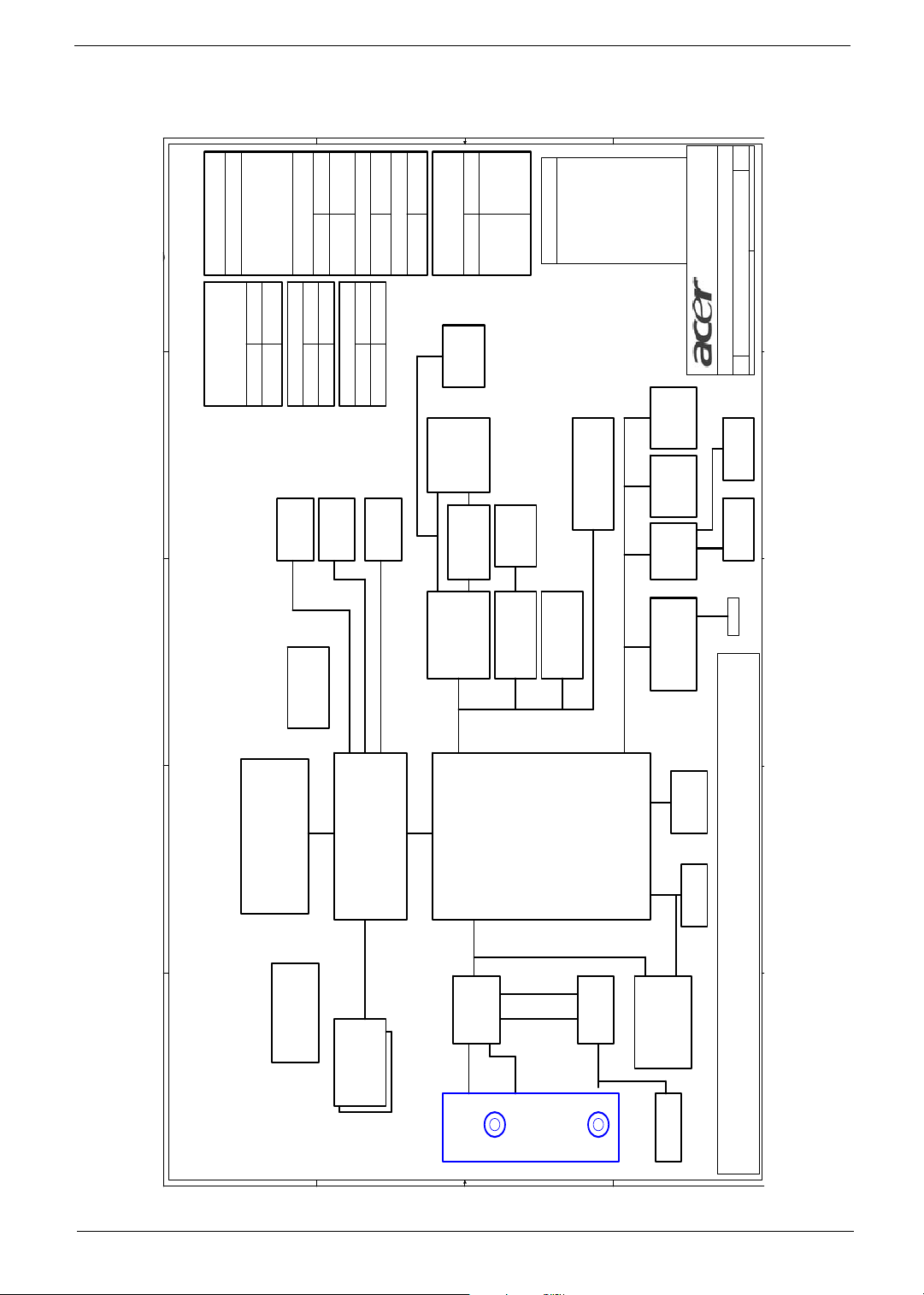
System Block Diagram
A
B
C
D
E
0
34
OUTPUTS
E
MAX1999
INPUTS
SYSTEM DC/DC
2
Switching Power
DC/DC IMVP4
D
03221-SB
Project Code
91.49Y01.001
C
3D3V_S5
5V_S5
5V_S3
5V_S0
3D3V_S3
3D3V_S0
3D3V_LAN_S5
5V_UP_S5
DCBATOUT
33
OUTPUTINPUTS
VCC_CORE
ISL6128CV-T
DCBATOUT
CRT
35
2D5V_S3
MAX1715
SYSTEM DC/DC
DCBATOUT
INPUTS OUTPUTS
36
OUTPUTSINPUTS
1D8V_S0
SI3012
2D5V_S3
CONN12LCD
XGA
17
G768D
1D35V_S0
36
G1211
11
RGB
35
SI3012
VCC_IO
OUTPUTSINPUTS
1D35V_S0
TV_OUT
LVDS
TV_OUT
2D5V_S3 1D5V_S0
CH7011
35
1D25V_S02D5V_S3
LP2996
13
37
14.8V
3.8A
OUTPUTSINPUTS
BT+
MAX1909
24
SMART
CARD
ONE SLOT
23 24
PWR SW
G574SA
23
OZ 711CE1
17/B/1
DCBATOUT
MAXIM CHARGER
CARDBUS
CARDBUS
PCI BUS
22
1394
CONN
22
TI1394
TSB43AB22
19/F/0
GND
Signal
Signal
L1:
L2:
L3:
PCB LAYER
25
802.11
Mini-PCI
22//C/E/2
20,21
LAN
BCM5705
21/D/4
SIGNAL
VCC
L4:
L5:
LPC BUS
SIGNAL
L6:
LPC
DEBUG
FWH
4MB
49LF004A
KBC
M38857
PC87392
NS SIO
CONN.
29 293031
SB
of
143Monday, July 21, 2003
Acer Incorporated
8F, 88, Sec.1, Hsin Tai Wu Rd., Hsichih,
Taipei Hsien 221, Taiwan, R.O.C.
TravelMate C300
BLOCK DIAGRAM
Custom
Title
Size Document Number Rev
Date: Sheet
INT KB
30 30
TOUCH
PAD
FIR
TV
OUT
LINE
OUT
4, 5
100MHz
B
Mobile
Banias
CPU
HOST BUS
3
CLK GEN.
ICS950813
A
6,7,8
66MHz
GMCH
DDR*2
333MHz
HUB I/F
Montara-GM+
9,10
AC-Link
AC'97
CODEC
CS4299XQ
ICH4-M
26
27
G1421
OP AMP
14,15,16
PIDE
MODEM
MDC Card
&Bluetooth
HDD
USB
19
18
19
2PORT
Port Replicator (100 PIN)
SEARIAL
LINE IN
MIC
PS2
USB*2
PRINTER
CRT
PORT
RJ45
Line Out
(SPDIF)
2 2
INT.SPKR
1 1
AC
IN
CANARY Block
Diagram
4 4
Line
In/Mic
In
3 3
Chapter 1 3
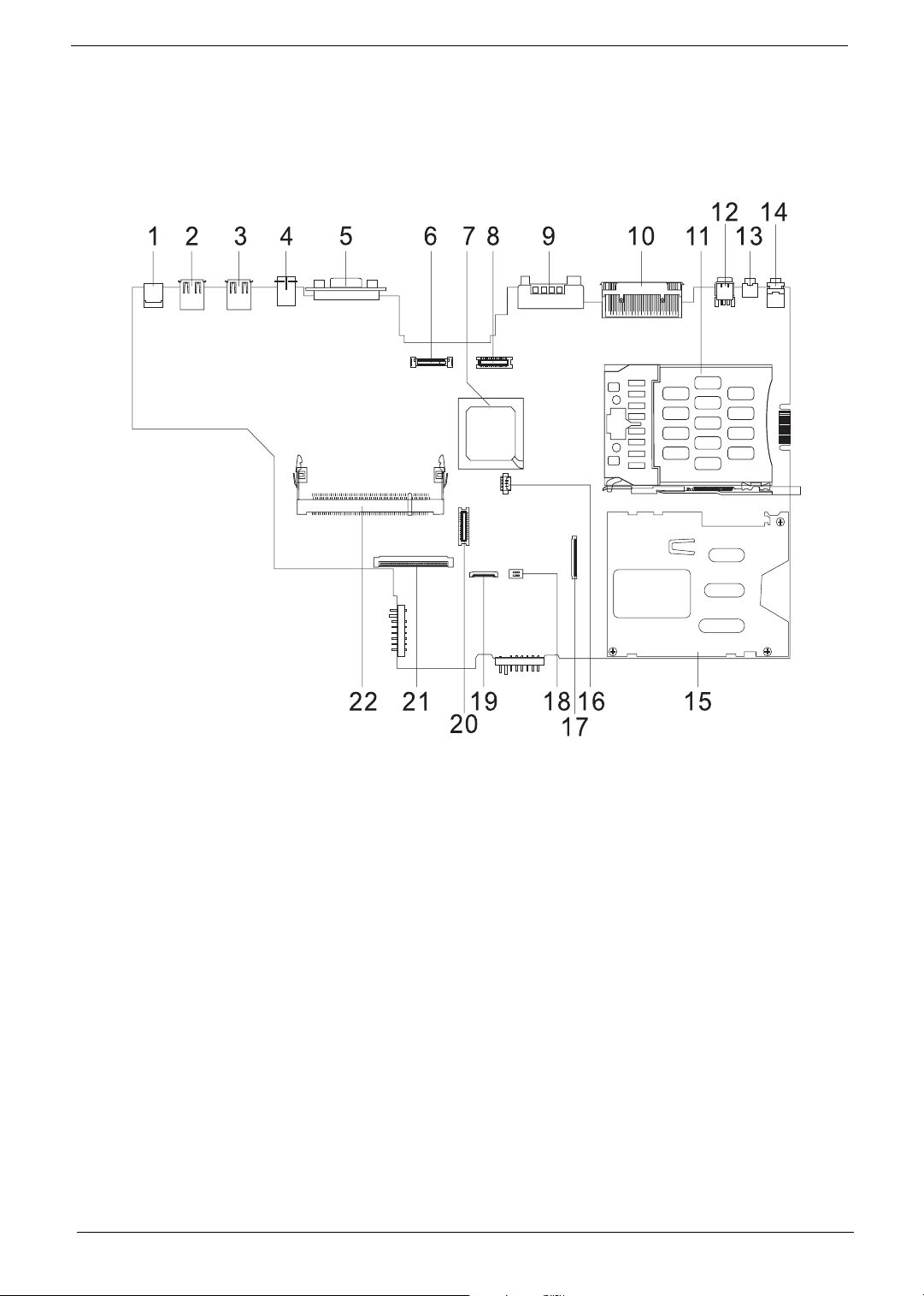
Board Layout
Top View
1 DC-In Jack 12 IEEE 1394 Port
2 USB Port 13 Line-Out Jack
3 USB Port 14 Mic-In Jack
4 S-Vedio Port 15 Smart Card Reader Slot
5 External Display Port 16 RTC Battery Connector
6 LCD Coaxial Cable Connector 17 Smart Card Connector
7 South Bridge 18 SW2
8 Inverter Cable Connector 19 Touchpad Connector
9 Modem Jack/LAN Jack 20 MDC Board Connector
10 Expansion Port 21 Keyboard Connector
11 PCMCIA Slot 22 DIMM Socket 2
4 Chapter 1
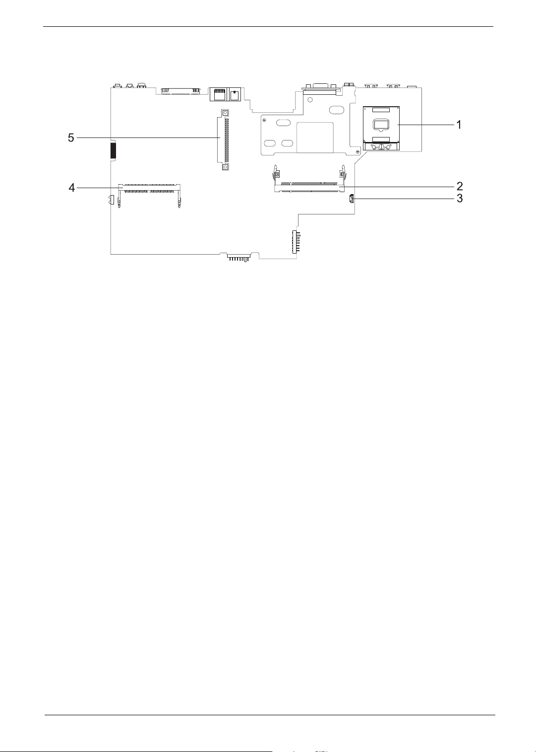
Bottom View
1 CPU Socket 4 Mini PCI Connector
2 DIMM Socket 1 5 HDD Connector
3 FAN Connector
Chapter 1 5
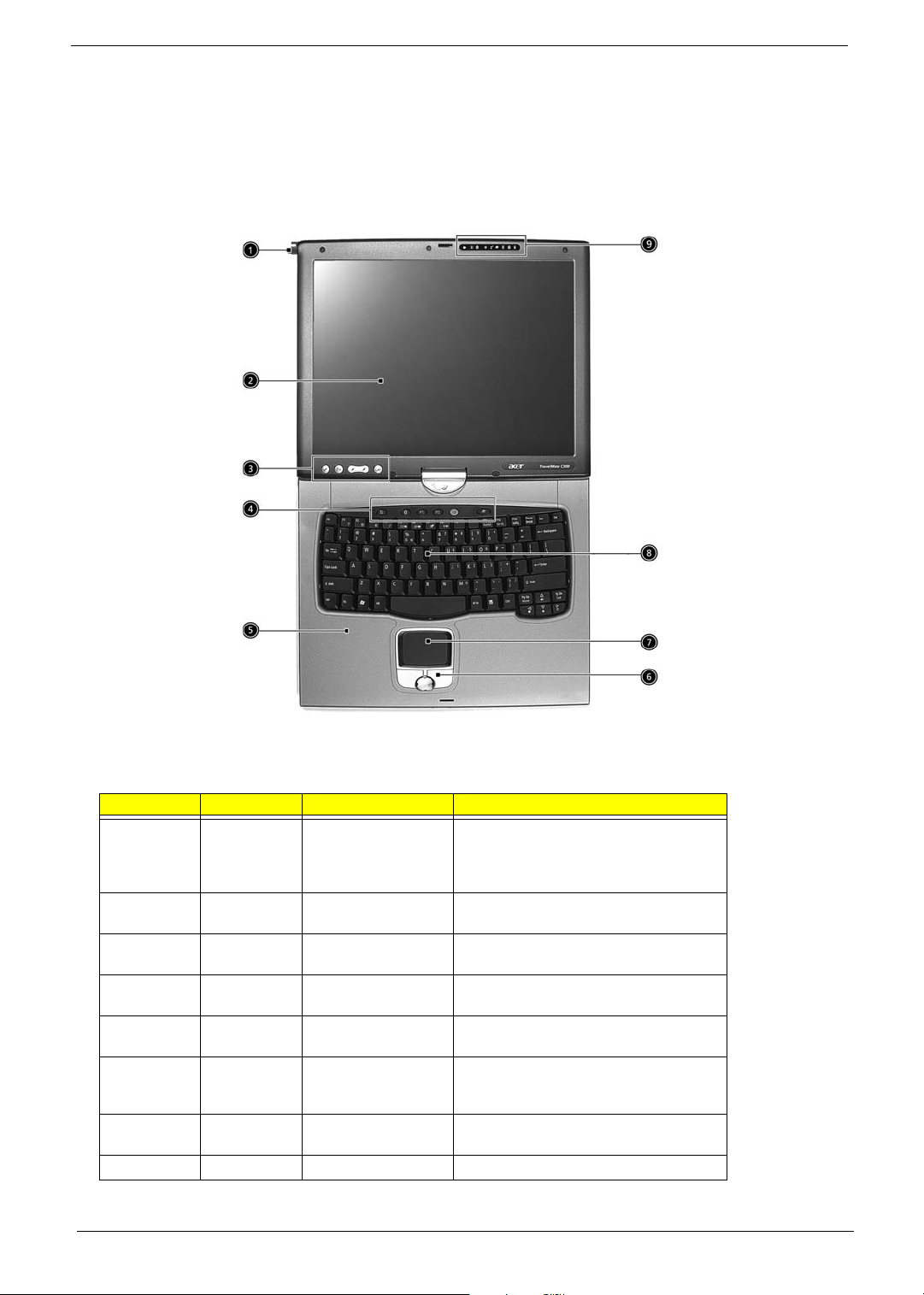
Outlook View
A general introduction of ports allow you to connect peripheral devices, as you would with a desktop PC.
Front View
# Icon Item Description
1 EMR stylus Electromagnetic resonate (EMR) stylus is
2 Display screen Also called LCD (liquid-crystal display),
3 Tablet Keys Add enhanced functionality when operating
4 Launch Keys Buttons for launching frequently used
5 Palmrest Comfortable support area for your hands
6 Click buttons (left,
center and right)
7 Touchpad Touch-sensitive pointing device which
8 Keyboard Inputs data into your computer.
used to input data in tablet mode. Use only
an EMR-compatible stylus to input data on
the screeen.
displays computer output.
in Tablet mode.
programs.
when you use the computer.
The left and right buttons function like the
left and right mouse buttons; the center
button serves as a 4-way scroll button.
functions like a computer mouse.
6 Chapter 1

9 Status indicator LEDs (light-emitting diodes) that turn on
and off to show the status of the computer,
its functions and component.
Chapter 1 7
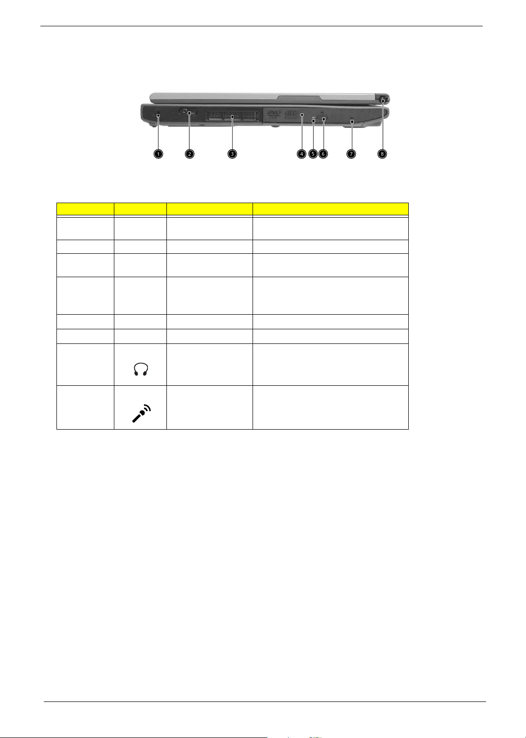
Left view
# Icon Item Description
1 Security keylock Connects to a Kensington-compatible
2 Power switch Turns on the computer power.
3 Ventilation slot Allows air to circulate through the computer
4 AcerMedia Bay
5 LED indicator
6 Eject button
7 Emergency eject slot
computer security lock.
chassis.
For hot-swappable modules including DVD-
ROM, DVD/CD-RW combo or DVD dual
drive.
Lights up when the optical drive is active.
Ejects the optical drive tray from the drive.
Ejects the optical drive tray when the com-
puter is turned off.
8 Pen slot
Keeps the stylus handy when not in use.
8 Chapter 1
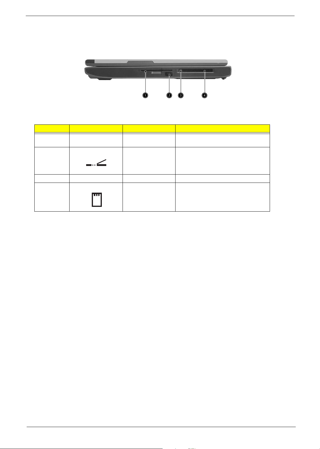
Right view
# Icon Item Description
1 Smart Card slot Slot for Smart Card interface with pre-boot
2 Infrared port Interfaces with infrared devices (e.g.,
3 PC Card eject button Ejects the PC Card from the slot.
4 PC Card slot Accepts one Type II 16-bit PC Card or 32-
authentication system.
infrared printer, IR-aware computer).
bit CardBus PC Card.
Chapter 1 9

Rear Panel
# Icon Item Description
1 Line-in/Mic-in jack
Accepts audio line-in devices (e.g., audio
CD player, stereo walkman).
2 Speaker/Line-out
Headphone jack
3 IEEE 1394 port Connects to IEEE 1394 devices.
4 Expansion port Connects to an I/O port replicator or Acer
5 Network jack Connects to a 10/100/1000 t-based Gigabit
6 Modem jack Connects to phone line.
7 Convertible hinge Hinges the LCD screen in place when
8 External display Connects to a display device (e.g., external
9 S-video Connects to a television or display device
10 USB 2.0 ports (2) Connects to Universal Serial Bus (USB) 2.0
Connects to audio line-out devices (e.g.,
speakers, headphones).
EasyPort port expansion device.
Ethernet network.
switching from PC mode to tablet mode
and vice versa.
monitor, LCD projector).
with S-video input.
devices (e.g., USB mouse, USB camera).
11 Power jack Connects to an AC adapter.
10 Chapter 1
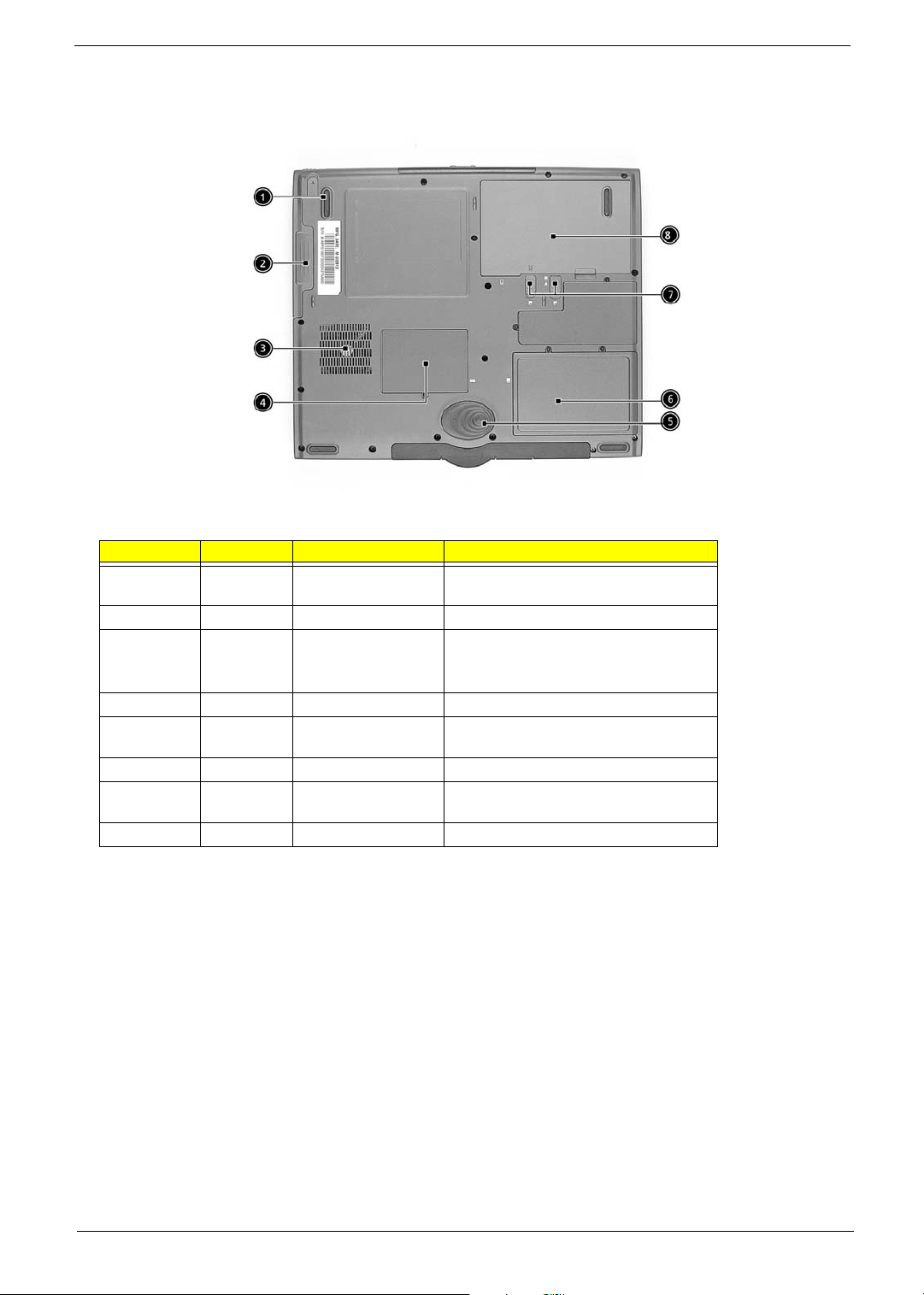
Bottom Panel
# Icon Item Description
1 AcerMedia Bay
2 AcerMedia Bay Houses an AcerMedia drive module.
3 Cooling fans Help keep the computer cool.
4 Memory compartment Houses the computer’s main memory.
5 Hard disk protector Protects the hard disk from accidental
6 Hard disk bay Houses the computers Hard disk drive.
7 Battery Lock & release
8 Battery bay Houses the computer’s battery pack.
release latch
latch
Unlatches the AcerMedia drive for
removing or swapping.
Note: Don’t cover or obstruct the opening
of the fans.
dumps and vibration.
Unlock and unlatches the battery to
remove the battery pack.
Chapter 1 11

Indicators
The computer has seven easy-to-read status icons below the display screen.
The status LCD displays icons that show the status of the computer and its components.
Icon Function Description
Wireless
communication
Bluetooth Lights when the Bluetooth is enabled or a
Power Lights when the computer is on.
Sleep Lights when the computer enters Standby
Media Activity Lights when the floppy drive, hard disk or
Battery Charge Lights when the battery is being charged.
Lights orange when the Wireless LAN
capabilities are enabled.
Bluetooth enabled device is within range.
mode and blinks when it enters into or
resumes from hibernation mode.
optical drive is active.
Caps lock Lights when Caps Lock is activated.
12 Chapter 1

Icon Function Description
Num loc Lights when Num Lock is activated.
Chapter 1 13
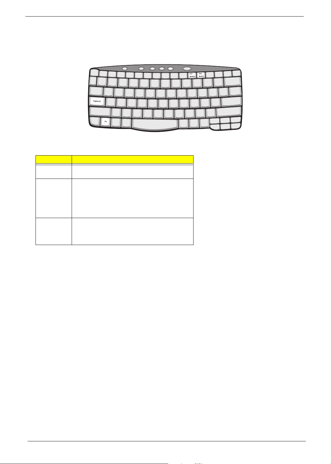
Lock Keys
The keyboard has three lock keys which you can toggle on and off.
Lock Key Description
Caps Lock When Caps Lock is on, all alphabetic characters typed
are in uppercase.
Num lock
(Fn-F11)
Scroll lock
(Fn-F12)
When Num Lock is on, the embedded keypad is in
numeric mode. The keys function as a calculator
(complete with the arithmetic operators +, -, *, and /).
Use this mode when you need to do a lot of numeric
data entry. A better solution would be to connect an
external keypad.
When Scroll Lock is on, the screen moves one line up
or down when you press the up or down arrow keys
respectively. Scroll Lock does not work with some
applications.
14 Chapter 1

Embedded Numeric Keypad
yy y
The embedded numeric keypad functions like a desktop numeric keypad. It is indicated by small characters
located on the upper right corner of the keycaps. To simplify the keyboard legend, cursor-control key symbols
are not printed on the keys.
Desired Access Num Lock On Num Lock Off
Number keys on embedded
keypad
Cursor-control keys on
embedded keypad
Main keyboard keys Hold Fn while typing letters
Type numbers in a normal
manner.
Hold j while using
cursor-control keys.
on embedded keypad.
Hold Fn while using cursorcontrol keys.
Type the letters in a normal
manner.
NOTE: If an external keyboard or keypad is connected to the computer, the Num Lock feature automatically
shifts from the internal keyboard to the external keyboard or keypad.
Chapter 1 15

Windows Keys
The keyboard has two keys that perform Windows-specific functions.
Key Icon Description
Windows logo
key
Start button. Combinations with this key perform
shortcut functions. Below are a few examples:
+ Tab (Activates next taskbar button)
+ E (Explores My Computer)
Application
key
+ F (Finds Document)
+ M (Minimizes All)
Shift + + M (Undoes Minimize All)
+ R (Displays the Run... dialog box)
Opens a context menu (same as a right-click).
16 Chapter 1
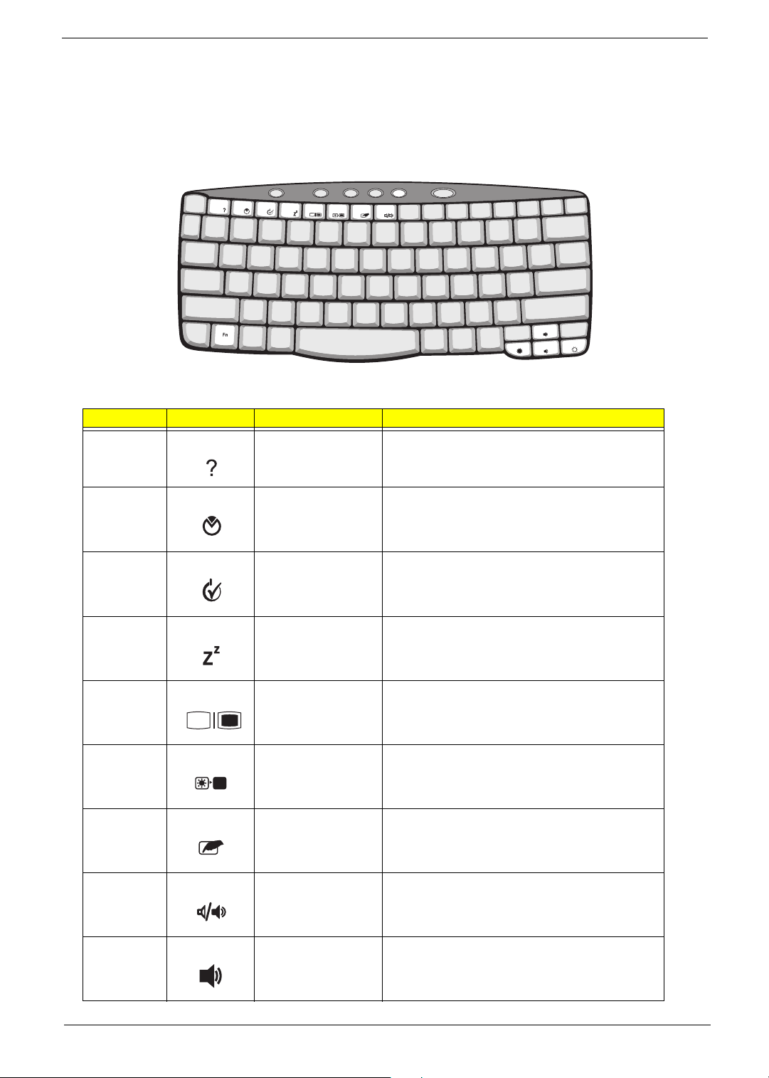
Hot Keys
The computer uses hotkey or key combinations to access most of the computer’s controls like sreen
brightness, volume output.
To activate hot keys, press and hold the Fn key before pressing the other key in the hot key combination.
Hot Key Icon Function Description
Fn-F1 Hot key help Displays help on hot keys.
Fn-F2 System Property Displays the System Property.
Fn-F3 Power Options Display the Power Options Properties used by the
computer (function available if supported by operating
system).
See “Power management” on page 25.
Fn-F4 Sleep Puts the computer in Sleep mode.
See “Power management” on page 25.
Fn-F5 Display toggle Switches display output between the display screen,
Fn-F6 Screen blank Turns the display screen backlight off to save power.
Fn-F7 Touchpad toggle Turns the internal touchpad on and off.
Fn-F8 Speaker toggle Turns the speakers on and off.
external monitor (if connected) and both the display
screen and external monitor.
Press any key to return.
Fn-w Volume up Increases the speaker volume.
Chapter 1 17
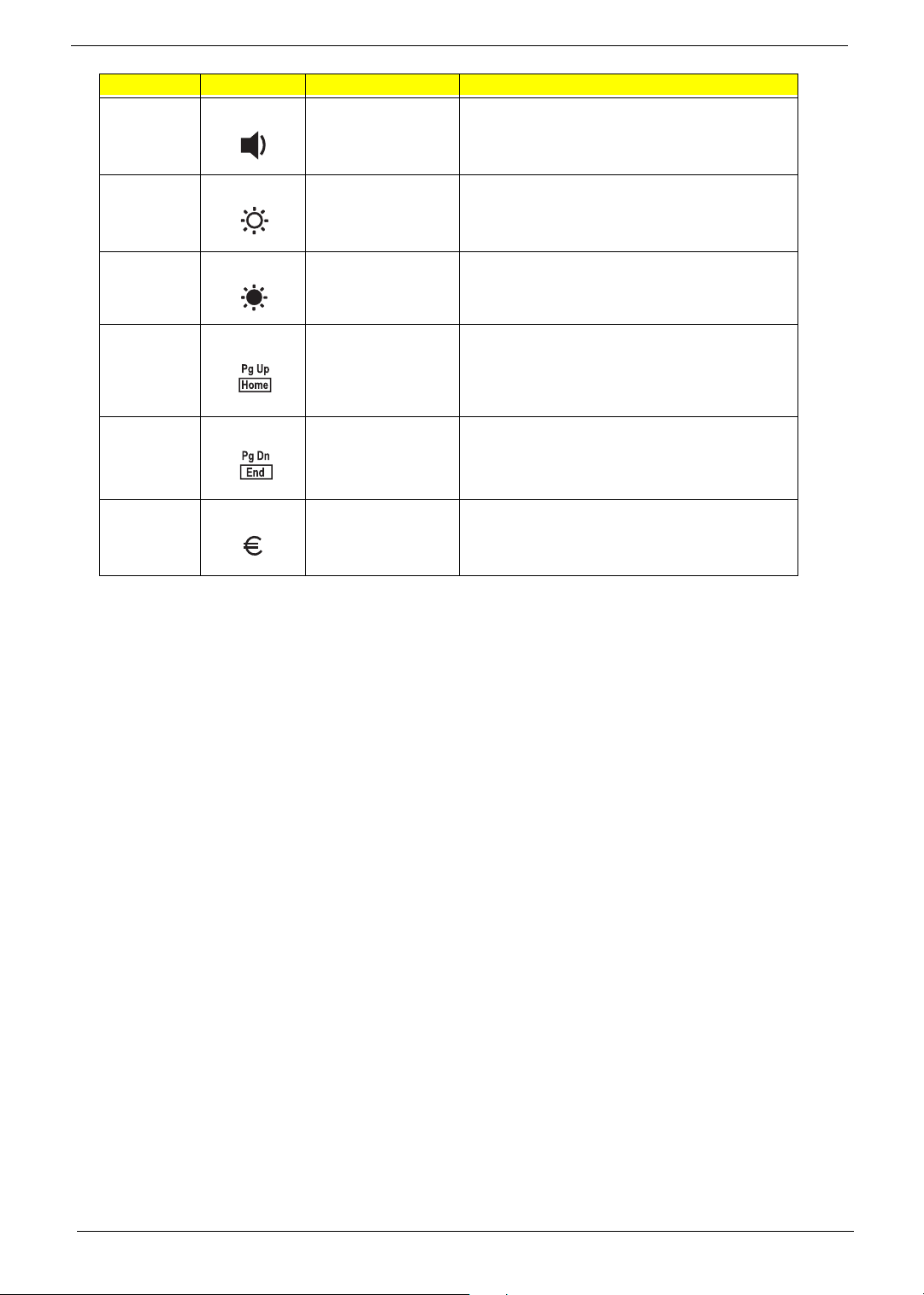
Hot Key Icon Function Description
Fn-y Volume down Decreases the speaker volume.
Fn-x Brightness up Increases the screen brightness.
Fn-z Brightness down Decreases the screen brightness
Fn-PgUp Home Functions as the “Home” key.
Fn-PgDn End Functions as the “End” key.
Alt Gr-Euro Euro Types the Euro symbol.
18 Chapter 1

The Euro Symbol
If your keyboard layout is set to United States-International or United Kingdom or if you have a keyboard with a
European layout, you can type the Euro symbol on your keyboard.
NOTE: For US keyboard users: The keyboard layout is set when you first set up Windows. For the Euro
symbol to work, the keyboard layout has to be set to United States-International.
To verify the keyboard type:
1. Click on Start, Control Panel.
2. Double-click on Regional and Language Options.
3. Click on the Language tab and click on Details.
4. Verify that keyboard layout used for “En English (United States)” is set to United States-International. If
not, select and click on ADD; then select United States-International and click on OK.
5. Click on OK.
To type the Euro symbol:
1. Locate the Euro symbol on your keyboard.
2. Open a text editor or word processor.
3. Hold Alt Gr and press the Euro symbol.
NOTE: Some fonts and software do not support the Euro symbol. Please refer to www.microsoft.com/
typography/faq/faq12.htm for more information.
Chapter 1 19
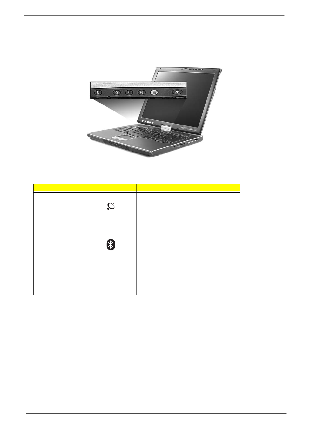
Launch Keys
Located at the top of keyboard are five buttons. These buttons are called launch keys. They are designated as
the mail button, the web browser button and two programmable buttons (P1 and P2).
No. Launch Key Default application
1
Activate wirelss LAN for wireless
communication
Wireless LAN
(optional)
2
Bluetooth (optional)
3 P1 User-programmable
4 P2 User-programmable
5 Email Email application
6 Web browser Internet browser application
Activate Bluetooth for wireless communication.
CAUTION: It’s important that Wireless LAN and Bluetooth is turned off before boarding an airplane.
20 Chapter 1
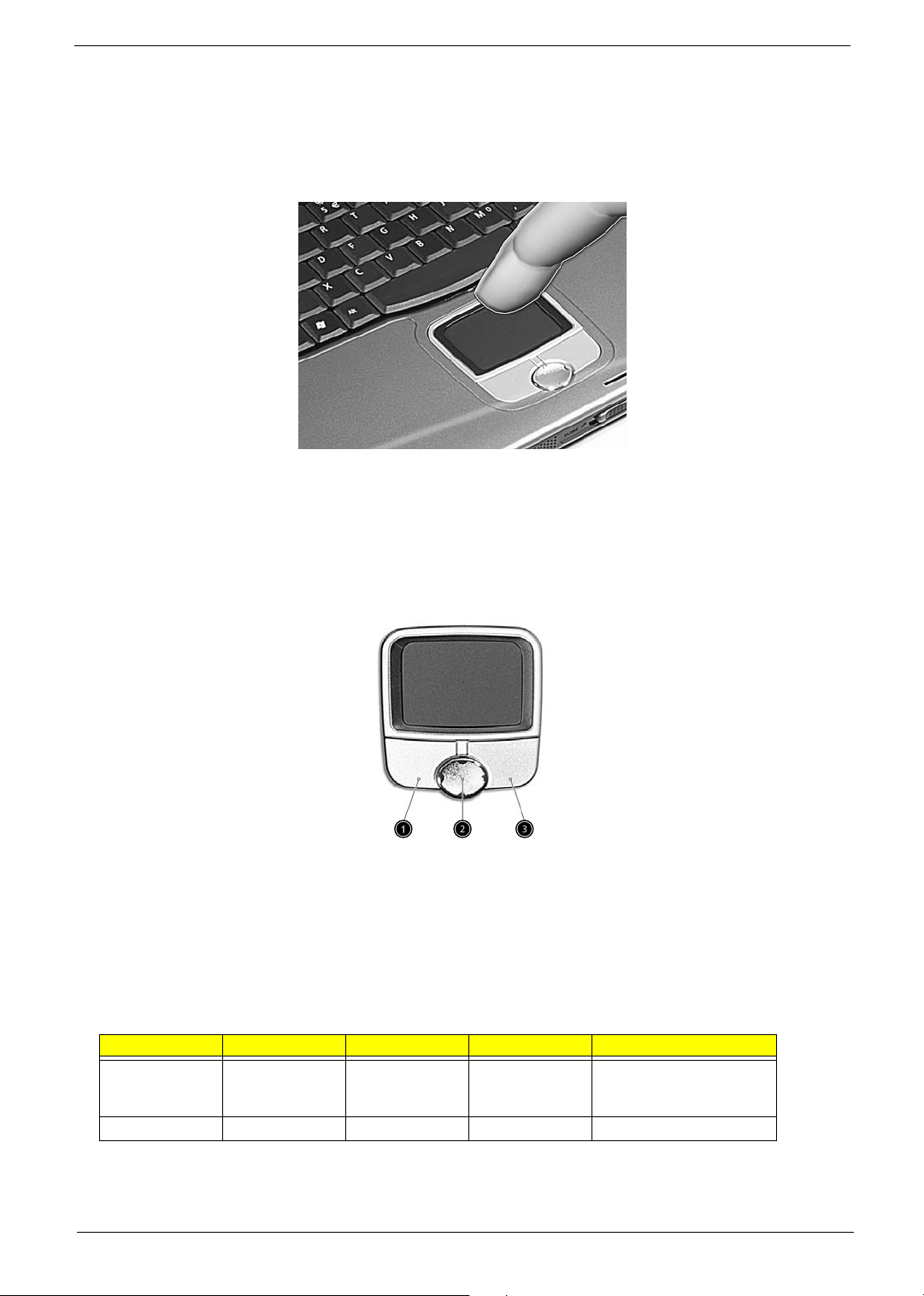
Touchpad
The built-in touchpad is a pointing device that senses movement on its surface. This means the cursor
responds as you move your finger on the surface of the touchpad. The central location on the palmrest
provides optimal comfort and support.
NOTE: If you are using an external USB mouse, you can press Fn-F7 to disable the touchpad.
Touchpad Basics
The following teaches you how to use the touchpad:
T Move your finger across the touchpad to move the cursor.
T Press the left (1) and right (3) buttons located on the edge of the touchpad to do selection and
execution functions. These two buttons are similar to the left and right buttons on a mouse.
Tapping on the touchpad produces similar results.
T Use the 4-way scroll (2) button to scroll up or down and move left or right a page. This button
mimics your cursor pressing on the right scroll bar of Windows applications.
Function Left Button Right Button Scroll Button Tap
Execute Click twice
quickly
Select Click once Tap once
Tap twice (at the same
speed as double-clicking
the mouse button)
Chapter 1 21

Function Left Button Right Button Scroll Button Tap
Drag Click and hold,
then use finger
to drag the
cursor on the
touchpad
Access context
menu
Scroll Click and hold
Click once
the button in the
desired
direction (up/
down/left/right)
Tap twice (at the same
speed as double-clicking
a mouse button) then hold
finger to the touchpad on
the second tap to drag the
cursor
NOTE: Keep your fingers dry and clean when using the touchpad. Also keep the touchpad dry and clean. The
touchpad is sensitive to finger movements. Hence, the lighter the touch, the better the response.
Tapping too hard will not increase the touchpad’s responsiveness.
22 Chapter 1
 Loading...