

Acer Travelmate 4330G Service Manual

TravelMate 4330 Series
Service Guide
Service guide files and updates are available
on the ACER/CSD web; for more information,
please refer to http://csd.acer.com.tw
PRINTED IN TAIWAN

Revision History
Please refer to the table below for the updates made on TravelMate 4330 Series service guide.
Date Chapter Updates
II

Copyright
Copyright © 2008 by Acer Incorporated. All rights reserved. No part of this publication may be reproduced,
transmitted, transcribed, stored in a retrieval system, or translated into any language or computer language, in
any form or by any means, electronic, mechanical, magnetic, optical, chemical, manual or otherwise, without
the prior written permission of Acer Incorporated.
Disclaimer
The information in this guide is subject to change without notice.
Acer Incorporated makes no representations or warranties, either expressed or implied, with respect to the
contents hereof and specifically disclaims any warranties of merchantability or fitness for any particular
purpose. Any Acer Incorporated software described in this manual is sold or licensed as is. Should the
programs prove defective following their purchase, the buyer (and not Acer Incorporated, its distributor, or its
dealer) assumes the entire cost of all necessary servicing, repair, and any incidental or consequential
damages resulting from any defect in the software.
Acer is a registered trademark of Acer Corporation.
Intel is a registered trademark of Intel Corporation.
Pentium and Pentium II/III are trademarks of Intel Corporation.
Other brand and product names are trademarks and/or registered trademarks of their respective holders.
III

Conventions
The following conventions are used in this manual:
SCREEN MESSAGES Denotes actual messages that appear
on screen.
NOTE Gives bits and pieces of additional
information related to the current
topic.
WARNING Alerts you to any damage that might
result from doing or not doing specific
actions.
CAUTION Gives precautionary measures to
avoid possible hardware or software
problems.
IMPORTANT Reminds you to do specific actions
relevant to the accomplishment of
procedures.
IV

Preface
Before using this information and the product it supports, please read the following general information.
1. This Service Guide provides you with all technical information relating to the BASIC CONFIGURATION
decided for Acer's global product offering. To better fit local market requirements and enhance product
competitiveness, your regional office MAY have decided to extend the functionality of a machine (e.g.
add-on card, modem, or extra memory capability). These LOCALIZED FEATURES will NOT be covered
in this generic service guide. In such cases, please contact your regional offices or the responsible
personnel/channel to provide you with further technical details.
2. Please note WHEN ORDERING FRU PARTS, that you should check the most up-to-date information
available on your regional web or channel. If, for whatever reason, a part number change is made, it will
not be noted in the printed Service Guide. For ACER-AUTHORIZED SERVICE PROVIDERS, your Acer
office may have a DIFFERENT part number code to those given in the FRU list of this printed Service
Guide. You MUST use the list provided by your regional Acer office to order FRU parts for repair and
service of customer machines.
V

VI

Table of Contents
System Specifications 1
Features . . . . . . . . . . . . . . . . . . . . . . . . . . . . . . . . . . . . . . . . . . . . . . . . . . . . . . . . . . . .1
System Block Diagram . . . . . . . . . . . . . . . . . . . . . . . . . . . . . . . . . . . . . . . . . . . . . . . . .4
Your Acer Notebook tour . . . . . . . . . . . . . . . . . . . . . . . . . . . . . . . . . . . . . . . . . . . . . . .5
Front View . . . . . . . . . . . . . . . . . . . . . . . . . . . . . . . . . . . . . . . . . . . . . . . . . . . . . . .5
Closed Front View . . . . . . . . . . . . . . . . . . . . . . . . . . . . . . . . . . . . . . . . . . . . . . . . .6
Left View . . . . . . . . . . . . . . . . . . . . . . . . . . . . . . . . . . . . . . . . . . . . . . . . . . . . . . . .7
Right View . . . . . . . . . . . . . . . . . . . . . . . . . . . . . . . . . . . . . . . . . . . . . . . . . . . . . . .8
Rear View . . . . . . . . . . . . . . . . . . . . . . . . . . . . . . . . . . . . . . . . . . . . . . . . . . . . . . .8
Bottom View . . . . . . . . . . . . . . . . . . . . . . . . . . . . . . . . . . . . . . . . . . . . . . . . . . . . .9
Indicators . . . . . . . . . . . . . . . . . . . . . . . . . . . . . . . . . . . . . . . . . . . . . . . . . . . . . .10
Easy-Launch Buttons . . . . . . . . . . . . . . . . . . . . . . . . . . . . . . . . . . . . . . . . . . . . .10
Touchpad Basics (with fingerprint reader) . . . . . . . . . . . . . . . . . . . . . . . . . . . . .11
Using the Keyboard . . . . . . . . . . . . . . . . . . . . . . . . . . . . . . . . . . . . . . . . . . . . . . . . . .12
Lock Keys and embedded numeric keypad . . . . . . . . . . . . . . . . . . . . . . . . . . . .12
Windows Keys . . . . . . . . . . . . . . . . . . . . . . . . . . . . . . . . . . . . . . . . . . . . . . . . . .13
Hot Keys . . . . . . . . . . . . . . . . . . . . . . . . . . . . . . . . . . . . . . . . . . . . . . . . . . . . . . .14
Special Key . . . . . . . . . . . . . . . . . . . . . . . . . . . . . . . . . . . . . . . . . . . . . . . . . . . . .15
Using the System Utilities . . . . . . . . . . . . . . . . . . . . . . . . . . . . . . . . . . . . . . . . . . . . . .16
Acer GridVista (dual-display compatible) . . . . . . . . . . . . . . . . . . . . . . . . . . . . . .16
Hardware Specifications and Configurations . . . . . . . . . . . . . . . . . . . . . . . . . . . . . . .18
System Utilities 29
BIOS Setup Utility . . . . . . . . . . . . . . . . . . . . . . . . . . . . . . . . . . . . . . . . . . . . . . . . . . . .29
Navigating the BIOS Utility . . . . . . . . . . . . . . . . . . . . . . . . . . . . . . . . . . . . . . . . .29
Information . . . . . . . . . . . . . . . . . . . . . . . . . . . . . . . . . . . . . . . . . . . . . . . . . . . . .30
Main . . . . . . . . . . . . . . . . . . . . . . . . . . . . . . . . . . . . . . . . . . . . . . . . . . . . . . . . . .31
Advanced . . . . . . . . . . . . . . . . . . . . . . . . . . . . . . . . . . . . . . . . . . . . . . . . . . . . . .32
Security . . . . . . . . . . . . . . . . . . . . . . . . . . . . . . . . . . . . . . . . . . . . . . . . . . . . . . . .34
Power . . . . . . . . . . . . . . . . . . . . . . . . . . . . . . . . . . . . . . . . . . . . . . . . . . . . . . . . .37
Boot . . . . . . . . . . . . . . . . . . . . . . . . . . . . . . . . . . . . . . . . . . . . . . . . . . . . . . . . . . .39
Exit . . . . . . . . . . . . . . . . . . . . . . . . . . . . . . . . . . . . . . . . . . . . . . . . . . . . . . . . . . .40
BIOS Flash Utility . . . . . . . . . . . . . . . . . . . . . . . . . . . . . . . . . . . . . . . . . . . . . . . . . . . .41
Remove HDD/BIOS Utility . . . . . . . . . . . . . . . . . . . . . . . . . . . . . . . . . . . . . . . . . . . . .43
Machine Disassembly and Replacement 47
Disassembly Requirements . . . . . . . . . . . . . . . . . . . . . . . . . . . . . . . . . . . . . . . . . . . .47
General Information . . . . . . . . . . . . . . . . . . . . . . . . . . . . . . . . . . . . . . . . . . . . . . . . . .48
Pre-disassembly Instructions . . . . . . . . . . . . . . . . . . . . . . . . . . . . . . . . . . . . . . .48
Disassembly Process . . . . . . . . . . . . . . . . . . . . . . . . . . . . . . . . . . . . . . . . . . . . .48
External Module Disassembly Process . . . . . . . . . . . . . . . . . . . . . . . . . . . . . . . . . . .49
External Modules Disassembly Flowchart . . . . . . . . . . . . . . . . . . . . . . . . . . . . .49
Removing the Battery Pack . . . . . . . . . . . . . . . . . . . . . . . . . . . . . . . . . . . . . . . .50
Removing the SD dummy card . . . . . . . . . . . . . . . . . . . . . . . . . . . . . . . . . . . . . .51
Removing the NewCard dummy card . . . . . . . . . . . . . . . . . . . . . . . . . . . . . . . . .52
Removing the Lower Covers . . . . . . . . . . . . . . . . . . . . . . . . . . . . . . . . . . . . . . . .53
Removing the DIMM Modules . . . . . . . . . . . . . . . . . . . . . . . . . . . . . . . . . . . . . . .55
Removing the WLAN Module . . . . . . . . . . . . . . . . . . . . . . . . . . . . . . . . . . . . . . .56
Removing the Hard Disk Drive Module . . . . . . . . . . . . . . . . . . . . . . . . . . . . . . . .58
Removing the Optical Drive Module . . . . . . . . . . . . . . . . . . . . . . . . . . . . . . . . . .60
Main Unit Disassembly Process . . . . . . . . . . . . . . . . . . . . . . . . . . . . . . . . . . . . . . . . .62
Main Unit Disassembly Flowchart . . . . . . . . . . . . . . . . . . . . . . . . . . . . . . . . . . . .62
Removing the Switch Cover . . . . . . . . . . . . . . . . . . . . . . . . . . . . . . . . . . . . . . . .64
Removing the Keyboard . . . . . . . . . . . . . . . . . . . . . . . . . . . . . . . . . . . . . . . . . . .65
VII

Table of Contents
Removing the Power Board . . . . . . . . . . . . . . . . . . . . . . . . . . . . . . . . . . . . . . . .66
Removing the Launch Board . . . . . . . . . . . . . . . . . . . . . . . . . . . . . . . . . . . . . . .67
Removing the Antenna . . . . . . . . . . . . . . . . . . . . . . . . . . . . . . . . . . . . . . . . . . . .68
Removing the LCD Module . . . . . . . . . . . . . . . . . . . . . . . . . . . . . . . . . . . . . . . . .70
Removing the Upper Cover . . . . . . . . . . . . . . . . . . . . . . . . . . . . . . . . . . . . . . . .72
Removing the Finger Print Reader . . . . . . . . . . . . . . . . . . . . . . . . . . . . . . . . . . .77
Removing the Touch Pad Bracket . . . . . . . . . . . . . . . . . . . . . . . . . . . . . . . . . . .79
Removing the Left Speaker Module . . . . . . . . . . . . . . . . . . . . . . . . . . . . . . . . . .81
Removing the Right Speaker Module . . . . . . . . . . . . . . . . . . . . . . . . . . . . . . . . .82
Removing the Bluetooth Module . . . . . . . . . . . . . . . . . . . . . . . . . . . . . . . . . . . . .83
Removing the Modem Module . . . . . . . . . . . . . . . . . . . . . . . . . . . . . . . . . . . . . .84
Removing the Mainboard . . . . . . . . . . . . . . . . . . . . . . . . . . . . . . . . . . . . . . . . . .85
Removing the USB Board . . . . . . . . . . . . . . . . . . . . . . . . . . . . . . . . . . . . . . . . . .88
Removing the RJ-11 Port . . . . . . . . . . . . . . . . . . . . . . . . . . . . . . . . . . . . . . . . . .89
Removing the Thermal Module . . . . . . . . . . . . . . . . . . . . . . . . . . . . . . . . . . . . . .90
Removing the CPU . . . . . . . . . . . . . . . . . . . . . . . . . . . . . . . . . . . . . . . . . . . . . . .92
Removing the VGA Module . . . . . . . . . . . . . . . . . . . . . . . . . . . . . . . . . . . . . . . .93
LCD Module Disassembly Process . . . . . . . . . . . . . . . . . . . . . . . . . . . . . . . . . . . . . .94
LCD Module Disassembly Flowchart . . . . . . . . . . . . . . . . . . . . . . . . . . . . . . . . .94
Removing the LCD Bezel . . . . . . . . . . . . . . . . . . . . . . . . . . . . . . . . . . . . . . . . . .95
Removing the Inverter Board . . . . . . . . . . . . . . . . . . . . . . . . . . . . . . . . . . . . . . .96
Removing the Camera Module . . . . . . . . . . . . . . . . . . . . . . . . . . . . . . . . . . . . . .97
Removing the LCD Panel . . . . . . . . . . . . . . . . . . . . . . . . . . . . . . . . . . . . . . . . . .99
Removing the LCD Brackets and FPC Cable . . . . . . . . . . . . . . . . . . . . . . . . . .100
Removing the Antennas . . . . . . . . . . . . . . . . . . . . . . . . . . . . . . . . . . . . . . . . . .101
Removing the MIC Module . . . . . . . . . . . . . . . . . . . . . . . . . . . . . . . . . . . . . . . .102
LCD Module Reassembly Procedure . . . . . . . . . . . . . . . . . . . . . . . . . . . . . . . . . . . .103
Replacing the LCD Panel . . . . . . . . . . . . . . . . . . . . . . . . . . . . . . . . . . . . . . . . .103
Replacing the LCD Bezel . . . . . . . . . . . . . . . . . . . . . . . . . . . . . . . . . . . . . . . . .107
Main Module Reassembly Procedure . . . . . . . . . . . . . . . . . . . . . . . . . . . . . . . . . . . .108
Replacing the VGA Module . . . . . . . . . . . . . . . . . . . . . . . . . . . . . . . . . . . . . . . .108
Replacing the CPU . . . . . . . . . . . . . . . . . . . . . . . . . . . . . . . . . . . . . . . . . . . . . .108
Replacing the Thermal Module . . . . . . . . . . . . . . . . . . . . . . . . . . . . . . . . . . . . .109
Replacing the RJ-11 Port . . . . . . . . . . . . . . . . . . . . . . . . . . . . . . . . . . . . . . . . .109
Replacing the Mainboard . . . . . . . . . . . . . . . . . . . . . . . . . . . . . . . . . . . . . . . . .111
Replacing the Modem Module . . . . . . . . . . . . . . . . . . . . . . . . . . . . . . . . . . . . .112
Replacing the Bluetooth Board . . . . . . . . . . . . . . . . . . . . . . . . . . . . . . . . . . . . .113
Replacing the Right Speaker Module . . . . . . . . . . . . . . . . . . . . . . . . . . . . . . . .114
Replacing the Launch Board . . . . . . . . . . . . . . . . . . . . . . . . . . . . . . . . . . . . . . .115
Replacing the Finger Print Reader . . . . . . . . . . . . . . . . . . . . . . . . . . . . . . . . . .116
Replacing the Touch Pad Bracket . . . . . . . . . . . . . . . . . . . . . . . . . . . . . . . . . .116
Replacing the Left Speaker Module . . . . . . . . . . . . . . . . . . . . . . . . . . . . . . . . .117
Replacing the Upper Cover . . . . . . . . . . . . . . . . . . . . . . . . . . . . . . . . . . . . . . . .118
Replacing the LCD Module . . . . . . . . . . . . . . . . . . . . . . . . . . . . . . . . . . . . . . . .119
Replacing the Antenna Cables . . . . . . . . . . . . . . . . . . . . . . . . . . . . . . . . . . . . .121
Replacing the Keyboard . . . . . . . . . . . . . . . . . . . . . . . . . . . . . . . . . . . . . . . . . .123
Replacing the Switch Cover . . . . . . . . . . . . . . . . . . . . . . . . . . . . . . . . . . . . . . .123
Replacing the WLAN Module . . . . . . . . . . . . . . . . . . . . . . . . . . . . . . . . . . . . . .125
Replacing the Hard Disk Drive Module . . . . . . . . . . . . . . . . . . . . . . . . . . . . . . .125
Replacing the DIMM Modules . . . . . . . . . . . . . . . . . . . . . . . . . . . . . . . . . . . . . .126
Replacing the ODD Module . . . . . . . . . . . . . . . . . . . . . . . . . . . . . . . . . . . . . . .127
Replacing the Lower Covers . . . . . . . . . . . . . . . . . . . . . . . . . . . . . . . . . . . . . . .127
Replacing the NewCard and SD Card Trays . . . . . . . . . . . . . . . . . . . . . . . . . .128
VIII

Table of Contents
Troubleshooting 129
Common Problems . . . . . . . . . . . . . . . . . . . . . . . . . . . . . . . . . . . . . . . . . . . . . . . . . .129
Power On Issue . . . . . . . . . . . . . . . . . . . . . . . . . . . . . . . . . . . . . . . . . . . . . . . .130
No Display Issue . . . . . . . . . . . . . . . . . . . . . . . . . . . . . . . . . . . . . . . . . . . . . . . .131
Random Loss of BIOS Settings . . . . . . . . . . . . . . . . . . . . . . . . . . . . . . . . . . . .132
LCD Failure . . . . . . . . . . . . . . . . . . . . . . . . . . . . . . . . . . . . . . . . . . . . . . . . . . . .133
Built-In Keyboard Failure . . . . . . . . . . . . . . . . . . . . . . . . . . . . . . . . . . . . . . . . .133
Touchpad Failure . . . . . . . . . . . . . . . . . . . . . . . . . . . . . . . . . . . . . . . . . . . . . . .134
Internal Speaker Failure . . . . . . . . . . . . . . . . . . . . . . . . . . . . . . . . . . . . . . . . . .134
Internal Microphone Failure . . . . . . . . . . . . . . . . . . . . . . . . . . . . . . . . . . . . . . .136
HDD Not Operating Correctly . . . . . . . . . . . . . . . . . . . . . . . . . . . . . . . . . . . . . .137
ODD Failure . . . . . . . . . . . . . . . . . . . . . . . . . . . . . . . . . . . . . . . . . . . . . . . . . . .138
USB Failure (Rightside) . . . . . . . . . . . . . . . . . . . . . . . . . . . . . . . . . . . . . . . . . .141
Modem Function Failure . . . . . . . . . . . . . . . . . . . . . . . . . . . . . . . . . . . . . . . . . .141
Wireless/WiMAX Function Failure . . . . . . . . . . . . . . . . . . . . . . . . . . . . . . . . . .142
Bluetooth Function Failure . . . . . . . . . . . . . . . . . . . . . . . . . . . . . . . . . . . . . . . .142
Robson Module Failure . . . . . . . . . . . . . . . . . . . . . . . . . . . . . . . . . . . . . . . . . . .143
EasyTouch Button Failure . . . . . . . . . . . . . . . . . . . . . . . . . . . . . . . . . . . . . . . . .143
Fingerprint Reader Failure . . . . . . . . . . . . . . . . . . . . . . . . . . . . . . . . . . . . . . . .144
Thermal Unit Failure . . . . . . . . . . . . . . . . . . . . . . . . . . . . . . . . . . . . . . . . . . . . .144
HDMI Switch Failure . . . . . . . . . . . . . . . . . . . . . . . . . . . . . . . . . . . . . . . . . . . . .145
External Mouse Failure . . . . . . . . . . . . . . . . . . . . . . . . . . . . . . . . . . . . . . . . . . .146
Other Failures . . . . . . . . . . . . . . . . . . . . . . . . . . . . . . . . . . . . . . . . . . . . . . . . . .146
Intermittent Problems . . . . . . . . . . . . . . . . . . . . . . . . . . . . . . . . . . . . . . . . . . . . . . . .147
Undetermined Problems . . . . . . . . . . . . . . . . . . . . . . . . . . . . . . . . . . . . . . . . . . . . . .147
POST Codes Tables . . . . . . . . . . . . . . . . . . . . . . . . . . . . . . . . . . . . . . . . . . . . . . . . .148
Port 80 POST Codes . . . . . . . . . . . . . . . . . . . . . . . . . . . . . . . . . . . . . . . . . . . .148
POST Keys and Messages . . . . . . . . . . . . . . . . . . . . . . . . . . . . . . . . . . . . . . . .150
Jumper and Connector Locations 151
Top View . . . . . . . . . . . . . . . . . . . . . . . . . . . . . . . . . . . . . . . . . . . . . . . . . . . . . . . . . .151
Bottom View . . . . . . . . . . . . . . . . . . . . . . . . . . . . . . . . . . . . . . . . . . . . . . . . . . . . . . .152
Clearing Password Check and BIOS Recovery . . . . . . . . . . . . . . . . . . . . . . . . . . . .153
Clearing Password Check . . . . . . . . . . . . . . . . . . . . . . . . . . . . . . . . . . . . . . . . .153
BIOS Recovery by Crisis Disk . . . . . . . . . . . . . . . . . . . . . . . . . . . . . . . . . . . . .154
FRU (Field Replaceable Unit) List 155
TravelMate 4330 Exploded Diagrams . . . . . . . . . . . . . . . . . . . . . . . . . . . . . . . . . . .156
Main Module . . . . . . . . . . . . . . . . . . . . . . . . . . . . . . . . . . . . . . . . . . . . . . . . . . .156
LCD Module . . . . . . . . . . . . . . . . . . . . . . . . . . . . . . . . . . . . . . . . . . . . . . . . . . .157
TravelMate 4330 FRU List . . . . . . . . . . . . . . . . . . . . . . . . . . . . . . . . . . . . . . . . . . . .158
Screw List . . . . . . . . . . . . . . . . . . . . . . . . . . . . . . . . . . . . . . . . . . . . . . . . . . . . .170
Model Definition and Configuration 172
TravelMate 4330 Series . . . . . . . . . . . . . . . . . . . . . . . . . . . . . . . . . . . . . . . . . . . . . .172
Test Compatible Components 195
Microsoft® Windows® Vista Environment Test . . . . . . . . . . . . . . . . . . . . . . . . . . . .196
Online Support Information 203
Index 205
IX

Table of Contents
X

System Specifications
Features
Below is a brief summary of the computer’s many feature:
NOTE: Items marked with * denote only selected models.
Operating System
• Genuine Windows® Vista™
Platform
• Intel® Celeron® processor*
• Mobile Intel® GL40 Express Chipset*
• Acer InviLink™ Nplify™ 802.11b/g/Draft-N*
• Acer InviLink™ 802.11b/g*
System Memory
Chapter 1
• Dual-Channel DDR2 SDRAM support
• Up to 2 GB of DDR2 667 MHz memory, upgradeable to 4 GB using two soDIMM modules*
Display and graphics
• 14.1" WXGA 1280 x 800
• Mobile Intel® GL40 Express Chipset*
• NVIDIA® GeForce® 9300M GS*
Storage subsystem
• 2.5" hard disk drive
• Intel® Turbo Memory supported*
• Optical drive options:
• Blu-ray Disc™/DVD-Super Multi double-layer drive*
• DVD-Super Multi double-layer drive*
• DVD/CD-RW combo drive*
• 5-in-1 card reader
Audio
• Two built-in Acer 3DSonic stereo speakers
• High-definition audio support
• MS-Sound compatible
• Built-in microphone
Chapter 1 1

Communication
• Acer Video Conference, featuring:
• Integrated Acer Crystal Eye webcam*
• Optional Acer Xpress VoIP phone*
• WLAN: Intel® Wireless WiFi Link 5100/5300*
• WiFIi®/WiMAX™: Intel® Wireless WiFi Link 5150/5350 (Subject to availability)
• WPAN: Bluetooth® 2.0+Enhanced Data Rate (EDR)*
• LAN: Gigabit Ethernet, Wake-on-LAN ready
• Modem: 56K ITU V.92
Privacy control
• Acer Bio-Protection fingerprint solution
• BIOS user, supervisor, HDD passwords
• Kensington lock slot
Dimensions and Weight
• 338 (W) x 247 (D) x 31/41 (H) mm (13.31 (W) x 9.72 (D) x 1.22/1.61 (H) inches)
• 2.35 kg (5.17 lbs.) with 6-cell battery pack*
• 2.51 kg (5.53 lbs.) with 9-cell battery pack*
Power subsystem
• ACPI 3.0
• 48.8W 4400 mAh
• 3-pin 65 W AC adapter*
• 3-pin 90 W AC adapter*
• Energy Star 4.0
Input Devices
• 88-/89-/93-key keyboard
• Touchpad pointing device
I/O interface
• PC Card slot (Type II)
• Acer Bio-Protection fingerprint reader*
• 5-in-1 card reader (SD™, MMC, MS, MS PRO, xD)
• 2 USB 2.0 ports
• HDMI™ port with HDCP support*
• External display (VGA) port
• Headphones/speaker/line-out jack
• Microphone-in jack
• Line-in jack
2 Chapter 1

• Ethernet (RJ-45) port
• Modem (RJ-11) port
• DC-in jack for AC adapter
Environment
• Temperature:
• Operating: 5 °C to 35 °C
• Non-operating: -20 °C to 65 °C
• Humidity (non-condensing):
• Operating: 20% to 80%
• Non-operating: 20% to 80%
NOTE: Items marked with * denote only selected models. The specifications listed above are for reference
only. The exact configuration of your PC depends on the model purchased.
Chapter 1 3
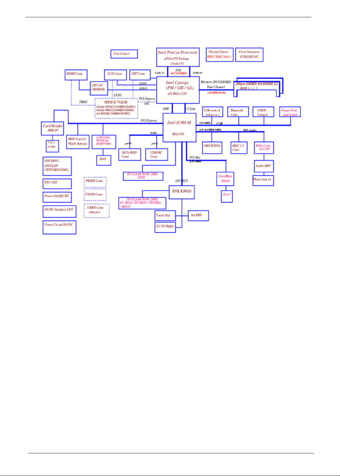
System Block Diagram
4 Chapter 1
Your Acer Notebook tour
After knowing your computer features, let us show you around your new computer.
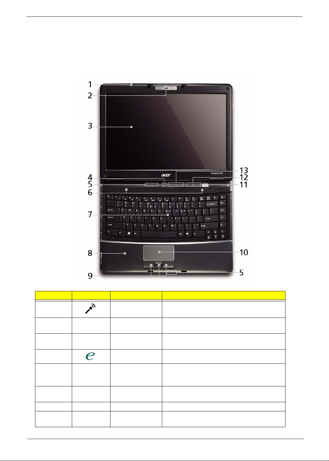
Front View
No. Icon Item Description
1 Microphone Internal microphone for sound recording.
2 Acer Crystal Eye Web camera for video communication (only for
certain models).
3 Display screen Also called Liquid-Crystal Display (LCD),
displays computer output.
4 Empowering key Launch Acer Empowering Technology.
5 Status indicators Light-Emitting Diodes (LEDs) that light up to
show the status of the computer's functions
and components.
6 Speakers Left and right speakers deliver stereo audio
output.
7 Keyboard For entering data into your computer.
8 Palmrest Comfortable support area for your hands when
you use the computer.
Chapter 1 5
No. Icon Item Description
9 Click buttons
(left, center* and
right)
10 T ouchpad T ouch-sensitive pointing device which functions
11 Power button Turns the computer on and off.
The left and right buttons function like the left
and right mouse buttons.
*The center button serves as Acer Bio-
Protection fingerprint reader supporting Acer
FingerNav 4-way control function (only for
certain models).
like a computer mouse.
12 Easy-launch
buttons
13 Productivity Keys Three productivity keys give users one-touch
Buttons for launching frequently used
programs.
access to protection and manageability
features for a more secure, smarter and easier
way to work.
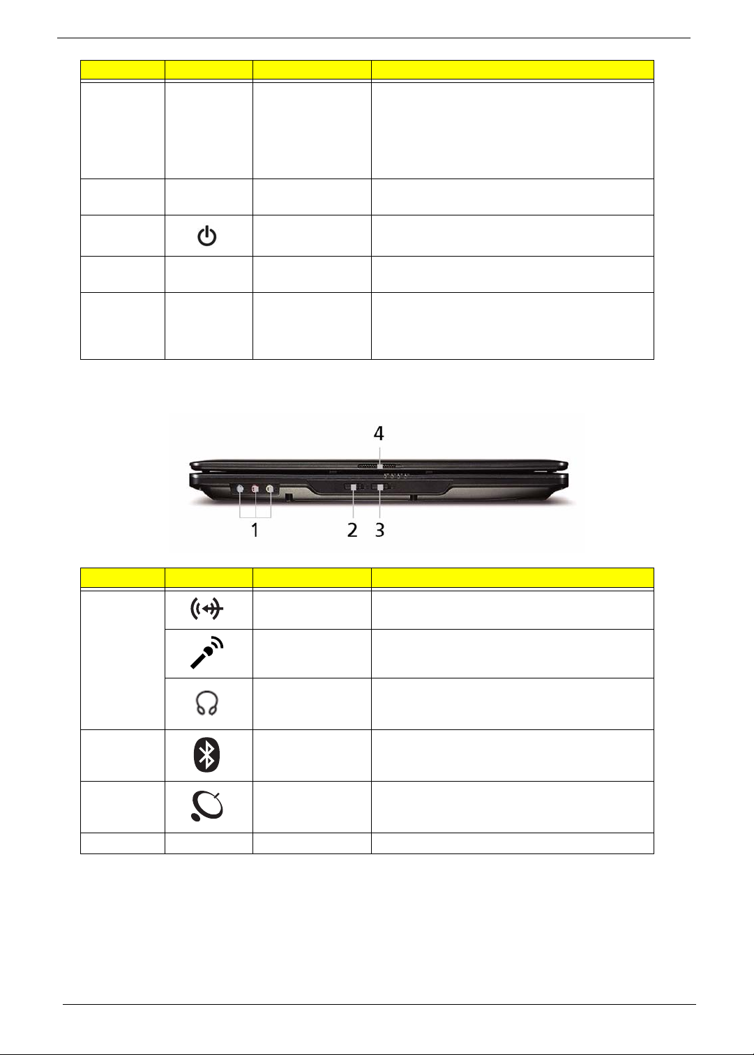
Closed Front View
No. Icon Item Description
1 Line-in jack Accepts audio line-in devices (e.g., audio CD
player, stereo walkman, mp3 player).
Microphone jack Accepts inputs from external microphones.
Headphones/
speaker/line-out
jack
2 Bluetooth
communication
switch
3 Wireless
communication
switch
4 Latch Locks and releases the lid.
6 Chapter 1
Connects to audio line-out devices (e.g.,
speakers, headphones).
Enables/disables the 3G/Bluetooth function.
(only for certain models).
Enables/disables the wireless function.
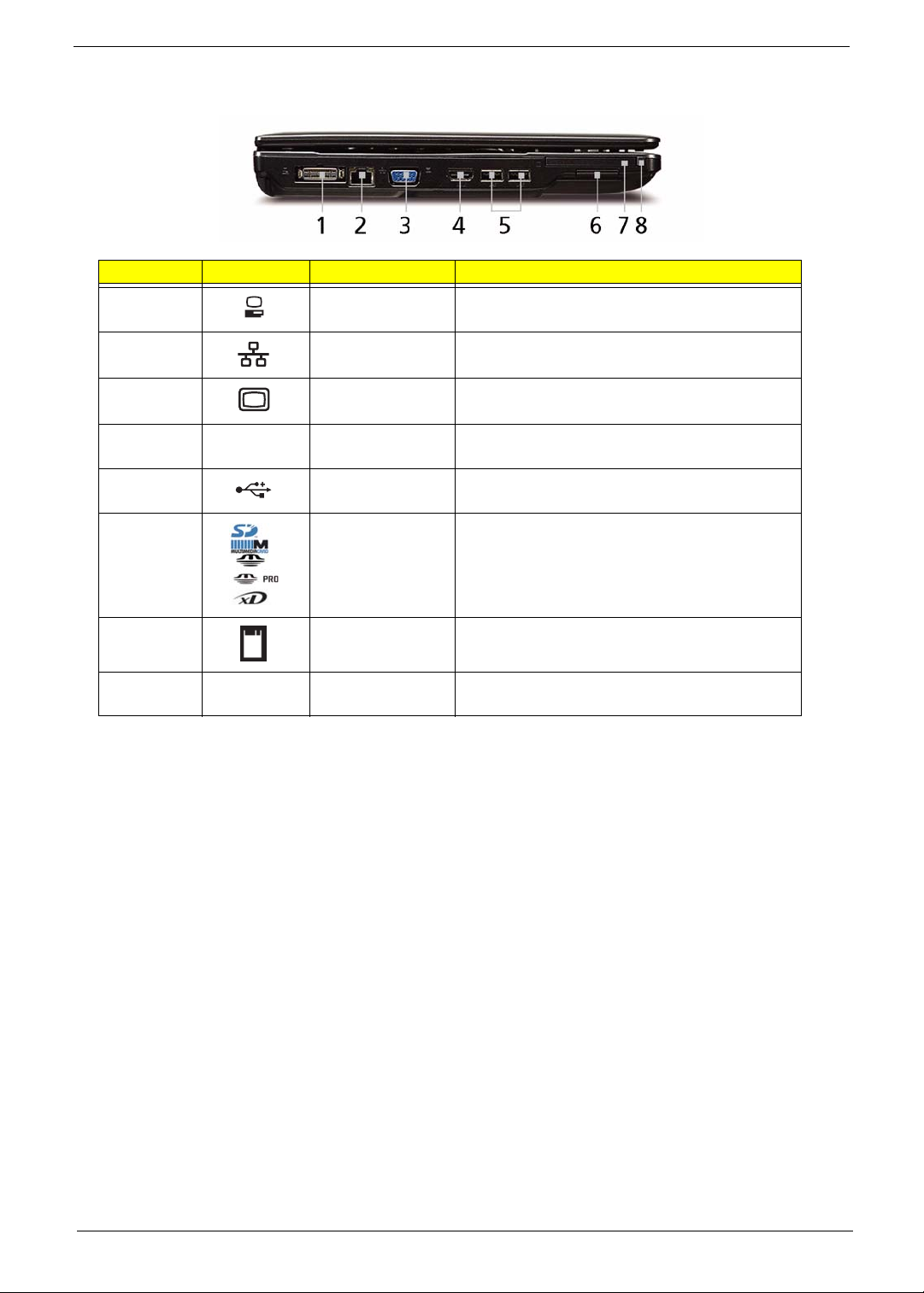
Left View
No. Icon Item Description
1 Acer EasyPort IV
connector
2 Ethernet (RJ-45)
port
3 External display
(VGA) port
4
5 2 USB 2.0 ports Connect to USB 2.0 devices (e.g. USB mouse,
6 5-in-1 card
7 PC Card slot Accepts one Type II PC Card.
HDMI
HDMI Connects to a television or display device with
reader
Connects to Acer EasyPort IV (only for certain
models).
Connects to an Ethernet 10/100/1000-based
network.
Connects to a display device
(e.g. external monitor, LCD projector).
HDMI input (only for certain models).
USB camera).
Accepts Secure Digital (SD), MultiMediaCard
(MMC), Memory Stick (MS), Memory Stick
PRO (MS PRO), xD-Picture Card (xD).
Note: Push to remove/install the card. Only
one card can operate at any given time.
8 PC Card slot
eject button
Ejects the PC Card from the slot.
Chapter 1 7
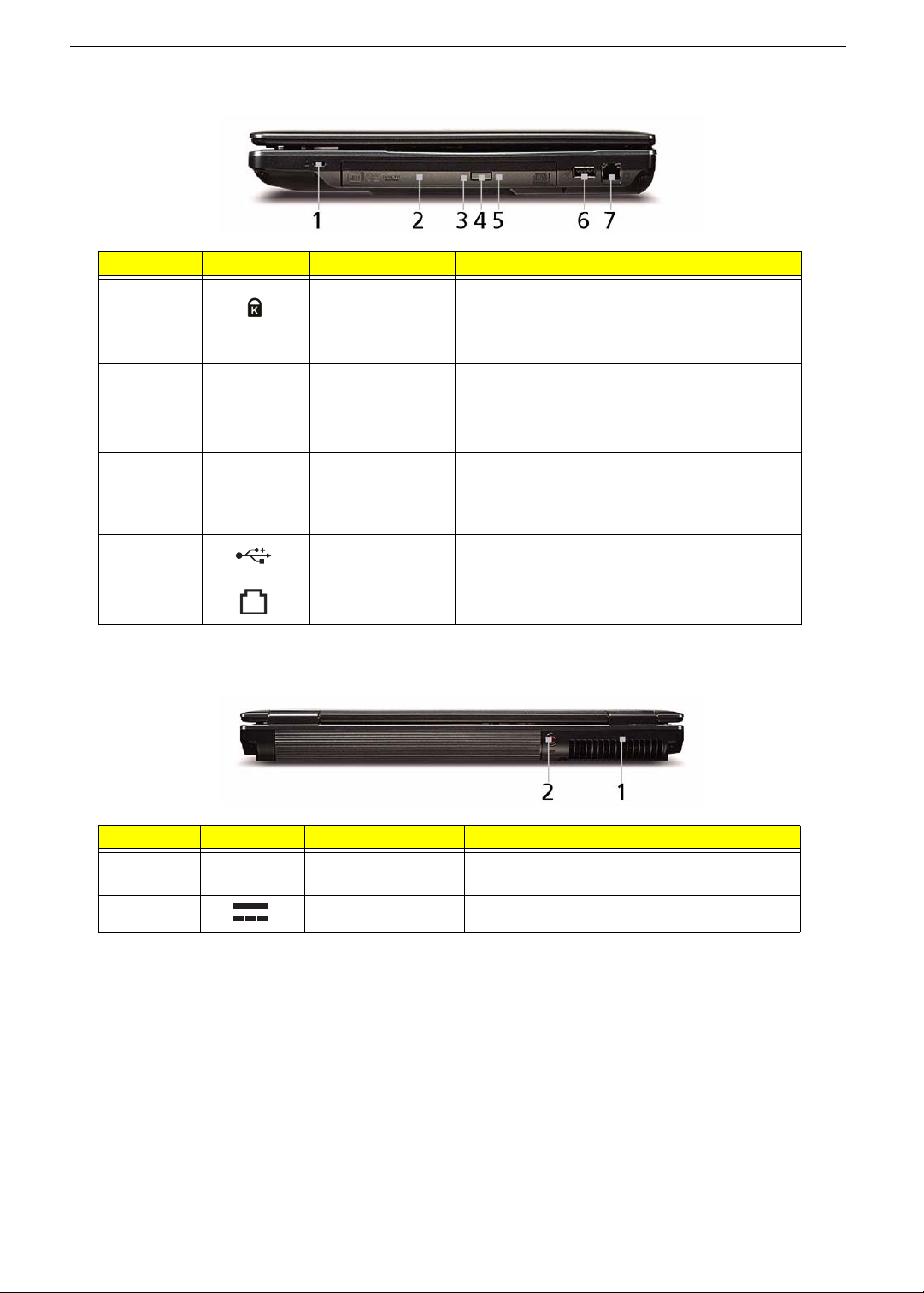
Right View
No. Icon Item Description
1 Kensington lock
slot
2 Optical drive Internal optical drive; accepts CDs or DVDs.
3 Optical disk access
indicator
4 Optical drive eject
button
5 Emergency eject
hole
6 USB 2.0 port Connect to USB 2.0 devices (e.g. USB mouse,
7 Modem (RJ-11)
port
Connects to a Kensington-compatible computer
security lock.
Lights up when the optical drive is active.
Ejects the optical disk from the drive.
Ejects the optical drive tray when the computer is
turned off. Note: Insert a paper clip into the
emergency eject hole to eject the optical drive
tray when the computer is off.
USB camera).
Connects to a phone line.
Rear View
No. Icon Item Description
1 Ventilation slots Enable the computer to stay cool, even after
prolonged use.
2 DC-in jack Connects to an AC adapter
8 Chapter 1
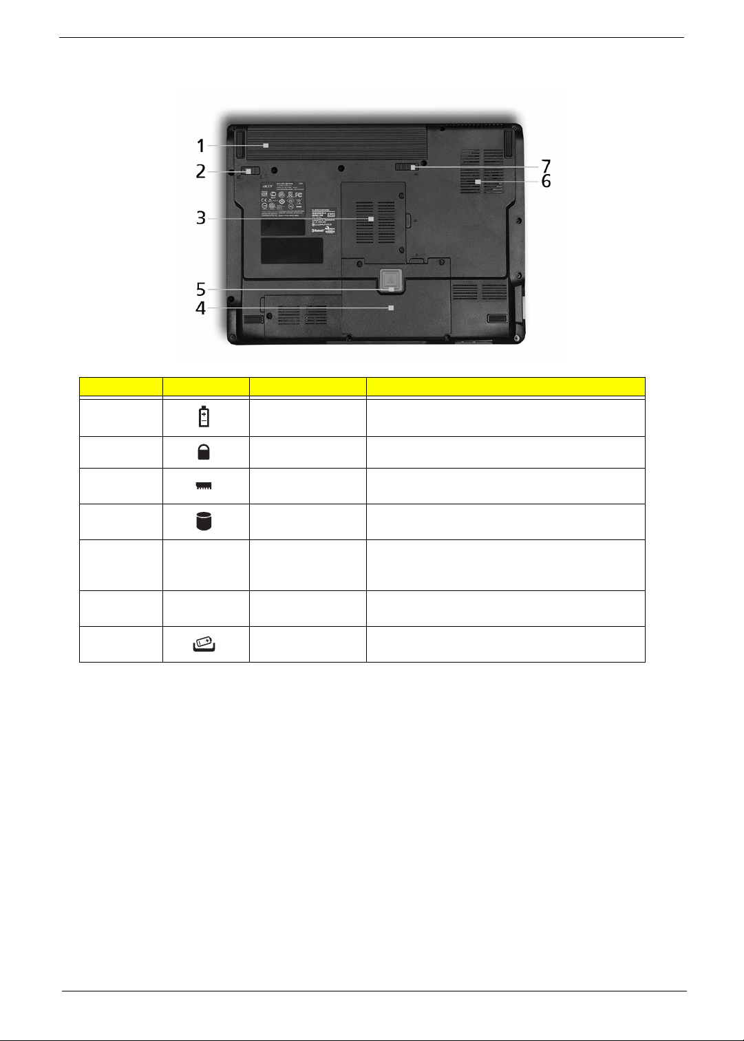
Bottom View
No. Icon Item Description
1 Battery bay Houses the computer's battery pack.
2 Battery lock Locks the battery in position.
3 Memory
compartment
4 Hard disk bay Houses the computer's hard disk (secured with
5 Acer DASP
(Disk Anti-Shock
Protection)
6 Ventilation slots
and cooling fan
7 Battery release
latch
Houses the computer's main memory.
screws).
Protects the hard disk drive from shocks
and bumps (only for certain models).
Enable the computer to stay cool, even after
prolonged use.
Releases the battery for removal.
Chapter 1 9
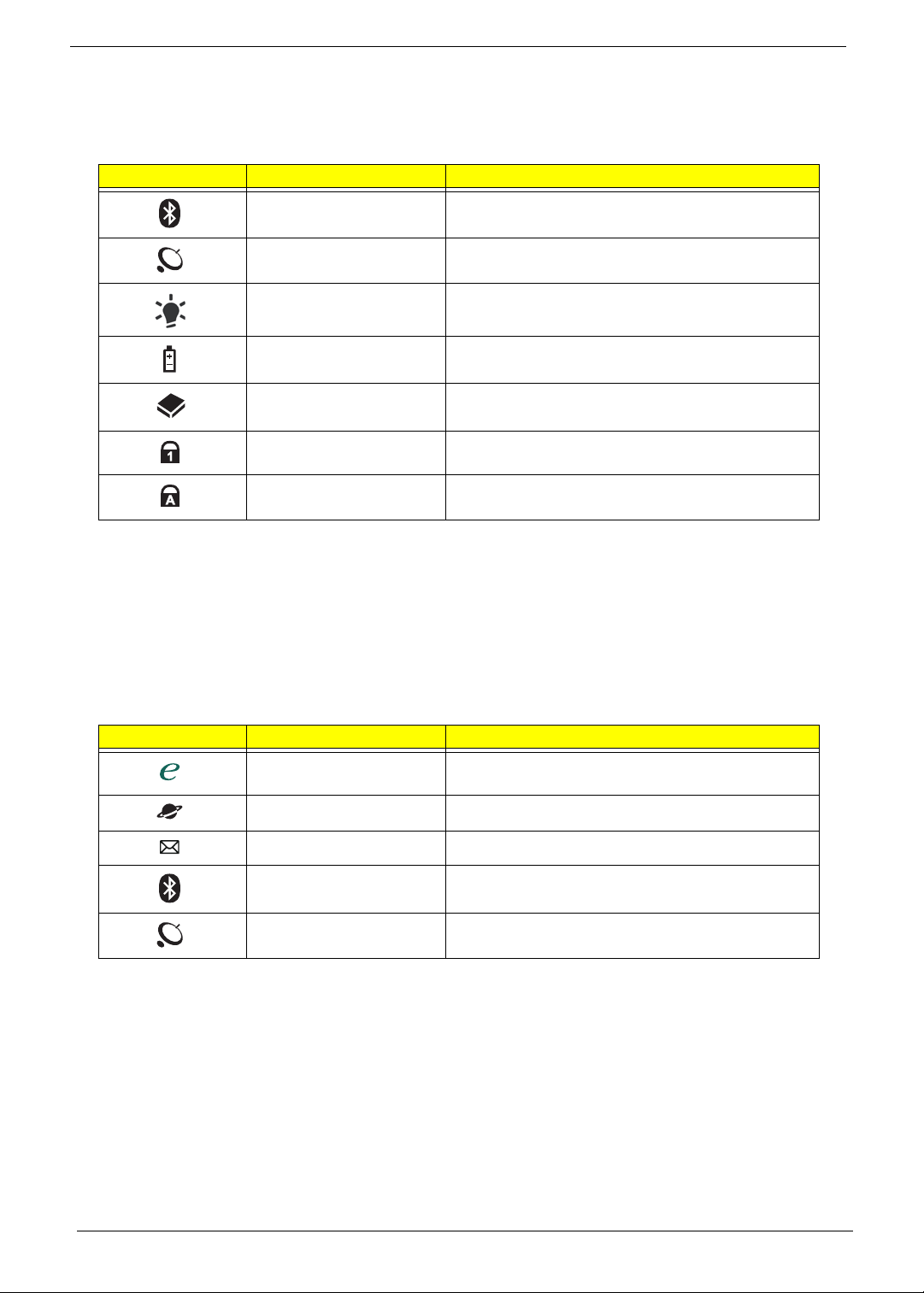
Indicators
The computer has several easy-to-read status indicators:
The front panel indicators are visible even when the computer cover is closed.
Icon Function Description
Bluetooth Indicates the status of Bluetooth communication.
WLAN Indicates the status of wireless LAN
communication.
Power Indicates the computer's power status.
Battery Indicates the computer's battery status.
HDD Indicates when the hard disk drive is active.
Num Lock Lights up when Num Lock is activated.
Caps Lock Lights up when Caps Lock is activated.
NOTE: 1. Charging: The battery light show s amber when the battery is charging. 2. Fully charged: The light
shows green when in AC mode.
Easy-Launch Buttons
Located beside the keyboard are application buttons. These buttons are called easy-launch buttons. They are:
WLAN, Internet, email, Bluetooth, Arcade and Acer Empowering Technology.
The mail and Web browser buttons are pre-set to email and Internet programs, but can be reset by users. To
set the Web browser, mail and programmable buttons, run the Acer Launch Manager.
Icon Function Description
Empowering Technology Laun ch Acer Empowering Technology.
(user-programmable)
Web browser Internet browser (user-Programmable)
Mail Email application (user-Programmable)
Bluetooth communication
switch
Wireless communication
switch
Enables/disables the Bluetooth function.
Enables/disables the wireless function.
10 Chapter 1
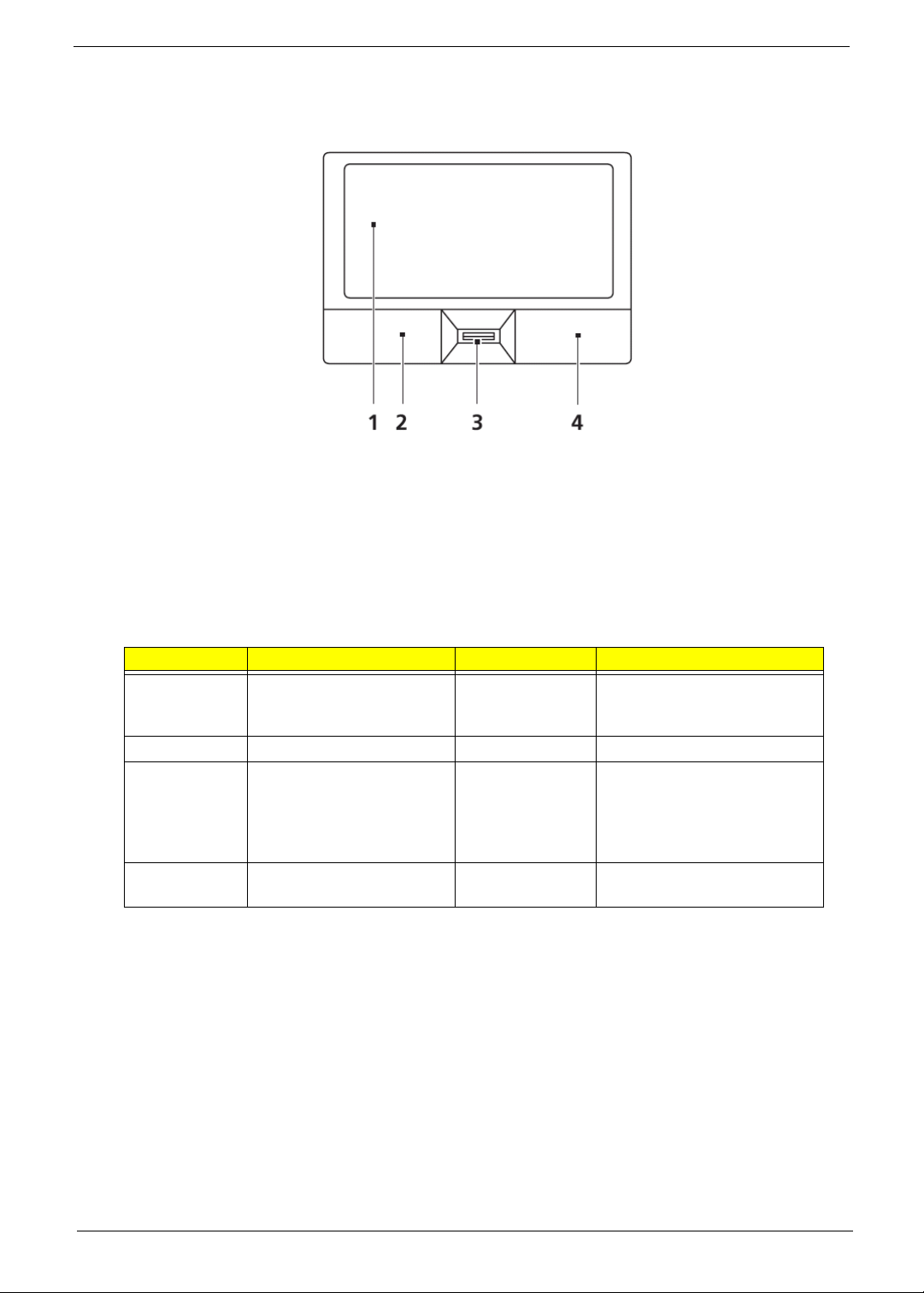
Touchpad Basics (with fingerprint reader)
The following items show you how to use the touchpad with Acer Bio-Protection fingerprint reader:
• Move your finger across the touchpad (1) to move the cursor.
• Press the left (2) and right (4) buttons located beneath the touchpad to perform selection and
execution functions. These two buttons are similar to the left and right buttons on a mouse.
Tapping on the touchpad is the same as clicking the left button.
• Use Acer Bio-Protection fingerprint reader (3) supporting Acer FingerNav 4-way control function
(only for certain models) or the 4-way scroll (3) button (only for certain models) to scroll up or down
and move left or right a page. This fingerprint reader or button mimics your cursor pressing on the
right scroll bar of Windows applications.
Function Left Button (2) Right Button (4) Main touchpad (1)
Execute Quickly click twice. Tap twice (at the same speed
as double-clicking a mouse
button).
Select Click once. Tap once.
Drag Click and hold, then use
finger on the touchpad to
drag the cursor.
Tap twice (at the same speed
as double-clicking a mouse
button); rest your finger on
the touchpad on the second
tap and drag the cursor.
Access
Click once.
context menu
NOTE: When using the touchpad, keep it - and your fingers - dry and clean. The touchpad is sensitive to finger
movement; hence, the lighter the touch, the better the response. Tapping too hard will not increase the
touchpad’s responsiveness.
Chapter 1 11
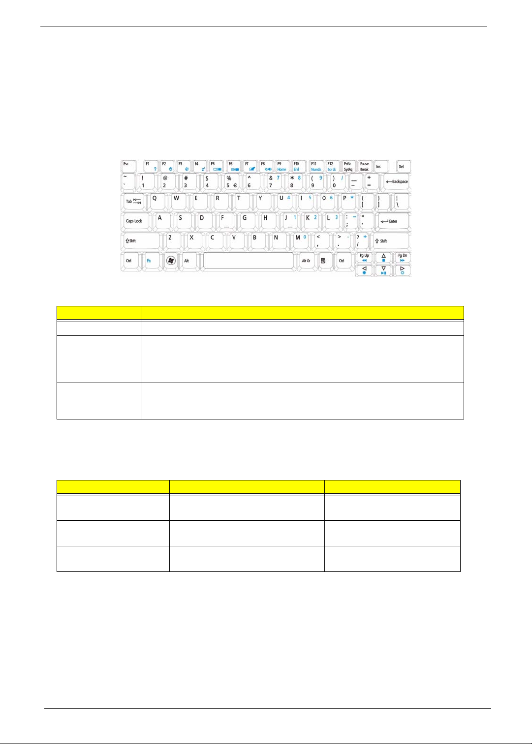
Using the Keyboard
The keyboard has full-sized keys and an embedded numeric keypad, separate cursor, lock, Windows, function
and special keys.
Lock Keys and embedded numeric keypad
The keyboard has three lock keys which you can toggle on and off.
Lock key Description
Caps Lock When Caps Lock is on, all alphabetic cha ra c ters typed are in uppercase.
Num Lock
<Fn> + <F11>
Scroll Lock <Fn> +
<F12>
When Num Lock is on, the embedded keypad is in numeric mode. The keys
function as a calculator (complete with the arithmetic operators +, -, *, and /). Use
this mode when you need to do a lot of numeric data entry. A better solution
would be to connect an external keypad.
When Scroll Lock is on, the screen moves one line up or down when you press
the up or down arrow keys respectively. Scroll Lock does not work with some
applications.
The embedded numeric keypad functions like a desktop numeric keypad. It is indicated by small characters
located on the upper right corner of the keycaps. To simplify the keyboard legend, cursor-control key symbols
are not printed on the keys.
Desired access Num Lock on Num Lock off
Number keys on
embedded keypad
Cursor-control keys on
embedded keypad
Main keyboard keys Hold <Fn> while typing letters on
Type numbers in a normal manner.
Hold <Shift> while using cursorcontrol keys.
embedded keypad.
Hold <Fn> while using cursorcontrol keys.
Type the letters in a normal
manner.
12 Chapter 1
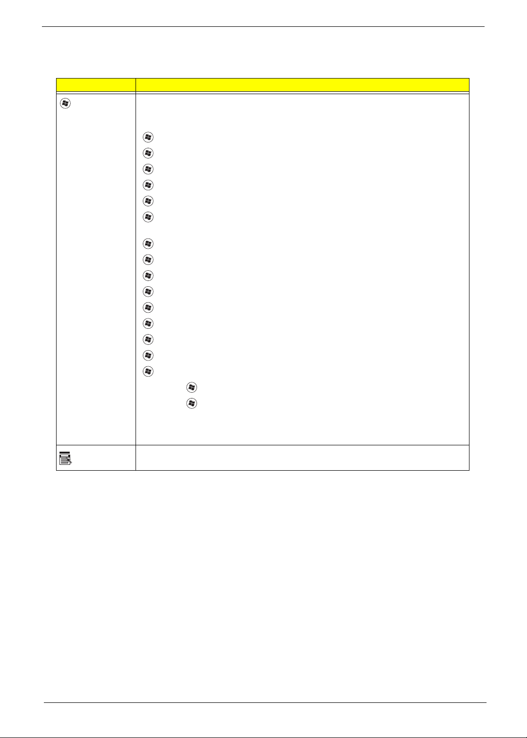
Windows Keys
The keyboard has two keys that perform Windows-specific functions.
Key Description
Windows key Pressed alone, this key has the same effect as clicking on the Windows Start button;
it launches the Start menu. It can also be used with other keys to provide a variety of
functions:
<>: Open or close the Start menu
<> + <D>: Display the desktop
<> + <E>: Open Windows Explore
<> + <F>: Search for a file or folder
<> + <G>: Cycle through Sidebar gadgets
<> + <L>: Lock your computer (if you are connected to a network domain), or
switch users (if you're not connected to a network domain)
<> + <M>: Minimizes all windows
<> + <R>: Open the Run dialog box
<> + <T>: Cycle through programs on the taskbar
<> + <U>: Open Ease of Access Center
<> + <X>: Open Windows Mobility Center
<> + <BREAK>: Display the System Properties dialog box
<> + <SHIFT+M>: Restore minimized windows to the desktop
<> + <TAB>: Cycle through programs on the taskbar by using Windows Flip 3-D
<> + <SPACEBAR>: Bring all gadgets to the front and select Windows Sidebar
Application
key
<CTRL> +
<CTRL> + <> + <TAB>: Use the arrow keys to cycle through programs on the
Note: Depending on your edition of Windows Vista, some shortcuts may not function
This key has the same effect as clicking the right mouse button; it opens the
application's context menu.
<> + <F>: Search for computers (if you are on a network)
taskbar by using Windows Flip 3-D
as described.
Chapter 1 13
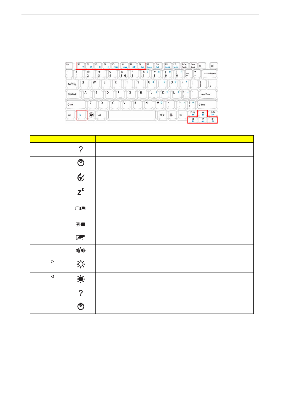
Hot Keys
The computer employs hotkeys or key combinations to access most of the computer’s controls like screen
brightness, volume output and the BIOS utility.
To activate hot keys, press and hold the <Fn> key before pressing the other key in the hotkey combination.
Hotkey Icon Function Description
<Fn> + <F1> Hotkey help Displays help on hotkeys.
<Fn> + <F2> Acer eSettings
Management
<Fn> + <F3> Acer ePower
Management
<Fn> + <F4> Sleep Puts the computer in Sleep mode.
<Fn> + <F5> Display toggle Switches display output between the display
<Fn> + <F6> Screen blank Turns the display screen backlight off to save
<Fn> + <F7> Touchpad toggle Turns the internal touchpad on and off.
<Fn> + <F8> Speaker toggle Turns the speakers on and off.
<Fn> + < > Brightness up Increases the screen brightness.
<Fn> + < > Brightness down Decreases the screen brightness.
<Fn> + <F1> Hotkey help Displays help on hotkeys.
<Fn> + <F2> Acer eSettings
Management
Launches Acer eSettings Management in Acer
Empowering Technology.
Launches Acer ePower Management in Acer
Empowering Technology.
screen, external monitor (if connected) and
both.
power. Press any key to return.
Launches Acer eSettings Management in Acer
Empowering Technology.
14 Chapter 1
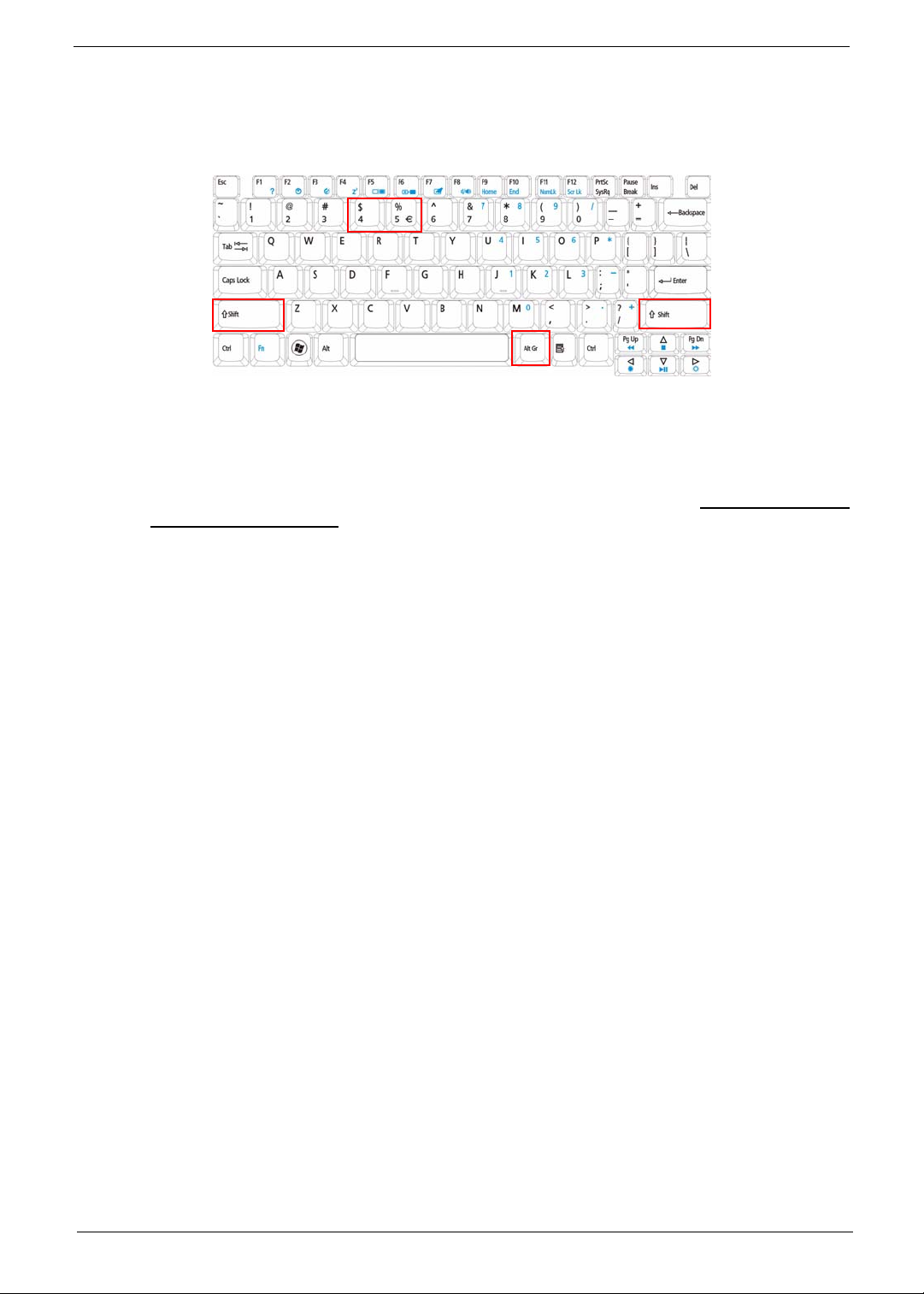
Special Key
You can locate the Euro symbol and the US dollar sign at the upper-center and/or bottom-right of your
keyboard.
The Euro symbol
1. Open a text editor or word processor.
2. Hold <Alt Gr> and then press the <5> key at the upper-center of the keyboard.
NOTE: Note: Some fonts and software do not support the Euro symbol. Please refer to www.microsoft.com/
typography/faq/faq12.htm for more information.
The US dollar sign
1. Open a text editor or word processor.
2. Hold <Shift> and then press the <4> key at the upper-center of the keyboard.
NOTE: This function varies by the operating system version.
Chapter 1 15
Using the System Utilities
Acer Bio-Protection (only for certain models) Acer Bio-Protection Fingerprint Solution is a multi-purpose
fingerprint software package integrated with the Microsoft Windows operating system. Utilizing the uniqueness
of one's fingerprint features, Acer Bio-Protection Fingerprint Solution has incorporated protection against
unauthorized access to your computer with centralized password management with Password Bank, easy
music player launching with Acer MusicLaunch, secure Internet favorites via Acer MyLaunch, and fast
application/website launching and login with Acer FingerLaunch, while Acer ProfileLaunch can launch up to
three applications/websites from a single finger swipe.
Acer Bio-Protection Fingerprint Solution also allows you to navigate through web browsers and documents
using Acer FingerNav. With Acer Bio-Protection Fingerprint Solution, you can now enjoy an extra layer of
protection for your personal computer, as well as the convenience of accessing your daily tasks with a simple
swipe of your finger!
For more information refer to the Acer Bio-Protection help files.
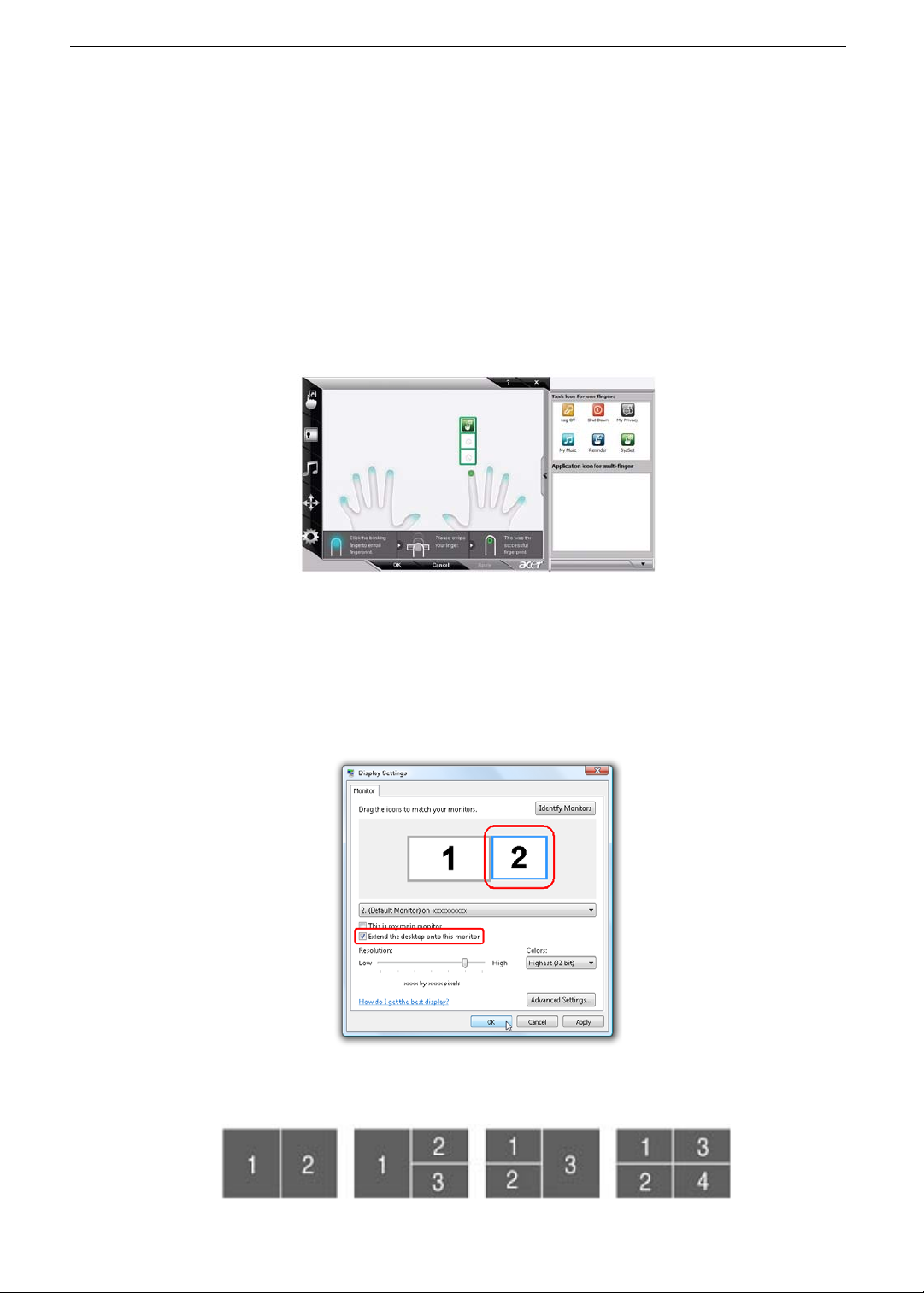
Acer GridVista (dual-display compatible)
NOTE: This feature is only available on certain models.
To enable the dual monitor feature of the notebook, first ensure that the second monitor is connected, then
select Start, Control Panel, Display and click on Settings. Select the secondary monitor (2) icon in the
display box and then click the check box Extend my windows desktop onto this monitor. Finally, click
Apply to confirm the new settings and click OK to complete the process.
Acer GridVista is a handy utility that offers four pre-defined display settings so you can view multiple windows
on the same screen. To access this function, please go to Start´ All Programs and click on Acer GridVista.
You may choose any one of the four display settings indicated below:
16 Chapter 1
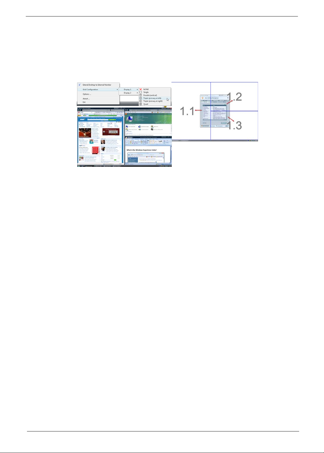
Double (vertical), Triple (primary at left), Triple (primary at right), or Quad Acer Gridvista is dual-display
compatible, allowing two displays to be partitioned independently.
Acer Gridvista is dual-display compatible, allowing two displays to be partitioned independently.
AcerGridVista is simple to set up:
1. Run Acer GridVista and select your preferred screen configuration for each display from the task bar.
2. Drag and drop each window into the appropriate grid.
3. Enjoy the convenience of a well-organized desktop.
NOTE: Please ensure that the resolution setting of the second monitor is set to the manufacturer's
recommended value.
Chapter 1 17
Hardware Specifications and Configurations
Processor
Item Specification
CPU type Intel® Celeron® processor (see Processor Specification table for more
information)
Core logic Mobile Intel® GL40 Express Chipset
CPU package Micro uPGA-478 Package
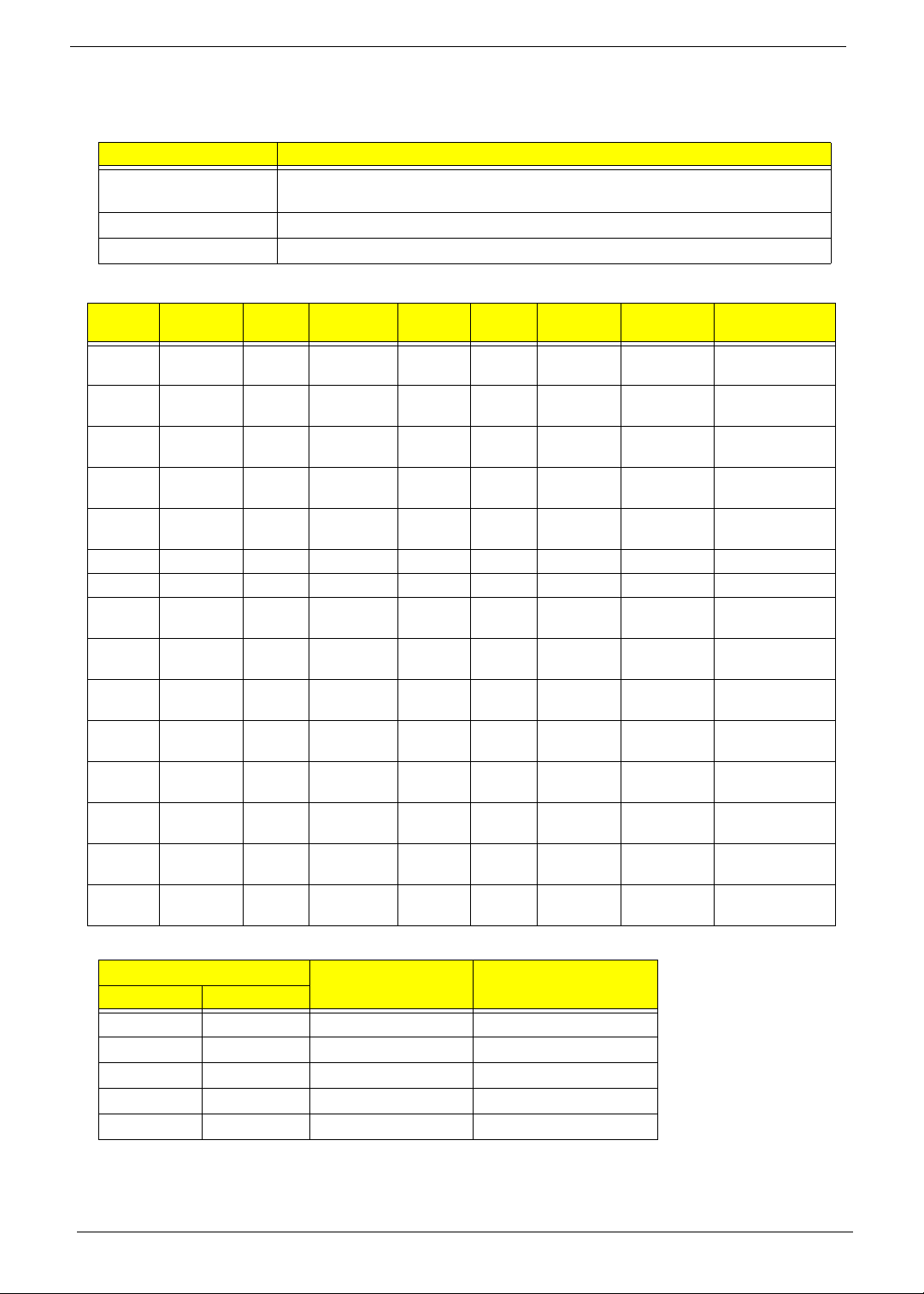
Processor Specification
Item
P9500 2.53 GHz 2 1066 MHz 45 nm 6 MB PGA 1.050V -
T9400 2.53 GHz 2 1066 MHz 45 nm 6 MB PGA 1.050V-
P8600 2.4 GHz 2 1066 MHz 45 nm 3 MB PGA 1.00V-
T9600 2.8 GHz 2 1066 MHz 45 nm 6 MB PGA 1.05V-
P8400 2.26 GHz 2 1066 MHz 45 nm 3 MB PGA 1.050V-
CM585 2.16 GHz 2 667 MHz 65 nm 1 MB PGA 0.95-1.30V KC.N0001.585
CM575 2.0 GHz 2 667 MHz 65 nm 1 MB PGA 0.95-1.30V KC.N0001.575
T5800 2.0 GHz 2 800 MHz 65 nm 2 MB PGA 1.075V-
T5900 2.2 GHz 2 800 MHz 65 nm 2 MB PGA 1.075V-
T3200 2.0 GHz 2 667 MHz 65 nm 1 MB PGA 1.075V-
T3400 2.16 GHz 2 667 MHz 65 nm 1 MB PGA 1.075V-
P7450 2.13 GHz 2 1066 MHz 45 nm 3 MB PGA 1.00V-
P7350 2.0 GHz 2 1066 MHz 45 nm 3 MB PGA 1.062C-
T1700 1.83 GHz 2 1066 MHz 65 nm 3 MB PGA 1.075V-
T1600 1.66 GHz 2 667 MHz 65 nm 1 MB PGA 1.075V-
CPU
Speed
Cores
Bus
Speed
Mfg
Tech
Cache
Size
Package
Core
Voltage
1.162V
1.162V
1.250V
1.2125V
1.150V
1.175V
1.175V
1.175V
1.175V
1.250V
1.150V
1.175V
1.175V
Acer P/N
KC.95001.DPP
KC.94001.DTP
KC.86R01.DPP
KC.96001.DTP
KC.84001.DPP
KC.58001.DTP
KC.59001.DTP
KC.32001.DTP
KC.34001.DTP
KC.74501.DPP
KC.73501.DPP
KC.17001.CMT
KC.16001.CMT
CPU Fan True Value Table
CPU Temperature
Core 0 Core 1
Fan Speed (RPM) SPL Spec (dBA)
58 58 2500 29
66 66 3000 31
74 74 3400 34
85 85 3800 37
100 100 4200 40
• Throttling 50%: On= 100°C; OFF=90°C
• OS shut down at 105°C; H/W shut down at 96°C
18 Chapter 1
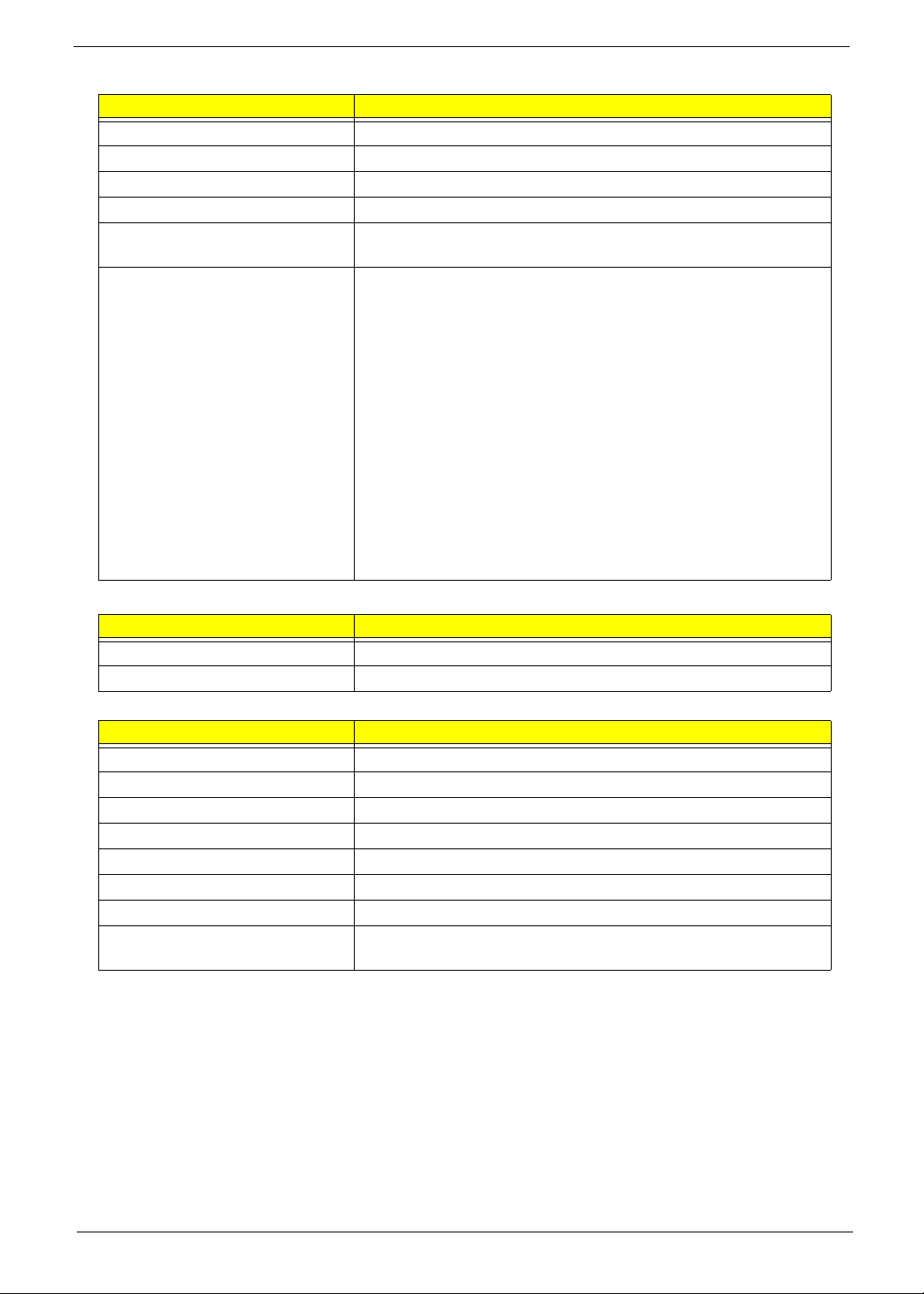
BIOS
Item Specification
BIOS vendor Phoenix
BIOS Version V0.19T1
BIOS ROM type Flash
BIOS ROM size 2MB
BIOS package ACPI 2.0 compliance with Intel Speed Step Support C1, C2, C3,
C4, C6 and S3, S4 for mobile CPU
Supported protocols
• Support ISIPP
• Support Acer UI
• Support multi-boot
• Suspend to RAM (S3)/Disk (S4)
• Va rious hot-keys for system control
• Support SMBUS 2.0, PCI2.3
• Support PXE
• Support Y2K solution
• Support Win Flash Wake on LAN from S3
• Wake on LAN form S4 in AC mode
• System information
• Support ASF 2.0
• Support iTPM (GM / PM Sku)
Cache
Item Specification
Cache controller CPU
Cache size 6MB L2 Cache on CPU
System Memory
Item Specification
Memory controller Built-in
Memory size 0MB (no on-board memory)
DIMM socket number 2 sockets
Supports memory size per socket 2 GB
Supports maximum memory size 4G for 64bit OS (with two 2GB SODIMM)
Supports DIMM type Two DDR SODIMM
Supports DIMM Speed DDR II 667 only (GL), 667/800 (GM,PM) SDRAM
Memory module combinations You can install memory modules in any combinations as long as
they match the above specifications.
Chapter 1 19
Memory Combinations
Slot 1 Slot 2 Total Memory
0MB 512MB 512MB
0MB 1024MB 1024MB
0MB 2048MB 2048MB
512MB 512MB 1024MB
512MB 1024MB 1536MB
512MB 2048MB 2560MB
1024MB 0MB 1024MB
1024MB 512MB 1536MB
1024MB 1024MB 2048MB
1024MB 2048MB 3072MB
2048MB 0MB 2048MB
2048MB 512MB 2560MB
2048MB 1024MB 3072MB
2048MB 2048MB 4096MB
NOTE: Above table lists some system memory configurations. You may combine DIMMs with various
capacities to form other combinations. On above table, the configuration of slot 1 and slot 2 could be
reversed.
Graphics Processing Unit
Item Specification
Chipset nVidia NB9M Family
Host Platform PCI Express 2.0
Memory Interface 64-bit DDR2/GDDR3
Process Technology 65 nm
Package 533-ball BGA 23 x 23 mm (GB1-64)
969-ball BGA 29 x 29 mm (GB1-128)
Features
• Unified Shader Architecture
• Microsoft® DirectX® 10 Shader Model 4 support
• OpenGL® 2.1 optimizations and support
• High-efficiency integrated adaptable Video Processor
(VP3)
• Integrated DisplayPort logic (two independent DP
devices)
• PCI Express 2.0
• High quality 10-bit display pipeline
• Integrated HDMI support
• S/PDIF and High Definition Audio (HDA) support
• SMBus support
• Internal Temperature Sensor
• Improved integrated Spread Spectrum support
• PowerMiser 8.0 Technology
• New 65nm process technology
20 Chapter 1
 Loading...