

Acer Travelmate 4020 Service Manual

Acer TravelMate 4020 Series
Service Guide
Service guide files and updates are available
on the ACER/CSD web; for more information,
please refer to http://csd.acer.com.tw
PRINTED IN TAIWAN

Revision History
Please refer to the table below for the updates made on TravelMate 4020 service guide.
Date Chapter Updates
01/12/2003 Chapter 2 Update BIOS specification.
II

Copyright
Copyright © 2005 by Acer Incorporated. All rights reserved. No part of this publication may be reproduced,
transmitted, transcribed, stored in a retrieval system, or translated into any language or computer language, in
any form or by any means, electronic, mechanical, magnetic, optical, chemical, manual or otherwise, without
the prior written permission of Acer Incorporated.
Disclaimer
The information in this guide is subject to change without notice.
Acer Incorporated makes no representations or warranties, either expressed or implied, with respect to the
contents hereof and specifically disclaims any warranties of merchantability or fitness for any particular
purpose. Any Acer Incorporated software described in this manual is sold or licensed "as is". Should the
programs prove defective following their purchase, the buyer (and not Acer Incorporated, its distributor, or its
dealer) assumes the entire cost of all necessary servicing, repair, and any incidental or consequential
damages resulting from any defect in the software.
Acer is a registered trademark of Acer Corporation.
Intel is a registered trademark of Intel Corporation.
Pentium and Pentium II/III are trademarks of Intel Corporation.
Other brand and product names are trademarks and/or registered trademarks of their respective holders.
III

Conventions
The following conventions are used in this manual:
SCREEN MESSAGES Denotes actual messages that appear
on screen.
NOTE Gives bits and pieces of additional
information related to the current
topic.
WARNING Alerts you to any damage that might
result from doing or not doing specific
actions.
CAUTION Gives precautionary measures to
avoid possible hardware or software
problems.
IMPORTANT Reminds you to do specific actions
relevant to the accomplishment of
procedures.
IV

Preface
Before using this information and the product it supports, please read the following general information.
1. This Service Guide provides you with all technical information relating to the BASIC CONFIGURATION
decided for Acer's "global" product offering. To better fit local market requirements and enhance product
competitiveness, your regional office MAY have decided to extend the functionality of a machine (e.g.
add-on card, modem, or extra memory capability). These LOCALIZED FEATURES will NOT be covered
in this generic service guide. In such cases, please contact your regional offices or the responsible
personnel/channel to provide you with further technical details.
2. Please note WHEN ORDERING FRU PARTS, that you should check the most up-to-date information
available on your regional web or channel. If, for whatever reason, a part number change is made, it will
not be noted in the printed Service Guide. For ACER-AUTHORIZED SERVICE PROVIDERS, your Acer
office may have a DIFFERENT part number code to those given in the FRU list of this printed Service
Guide. You MUST use the list provided by your regional Acer office to order FRU parts for repair and
service of customer machines.
V

VI

System Specifications
Features
This computer was designed with the user in mind. Here are just a few of its many features:
Performance
T Intel
T Intel
T CPU Package is uFPGA 478 Package
T Integrated Intel
Memory
T 256MB or 512MB of DDRII 400/533
T Upgradeable to 2GB Memory by Dual channels of SODIMM
T 512KB flash ROM BIOS
®
915GM PCI Express chipset
®
Pentium® M processor 725 (2MB L2 cache, 1.6 GHz, 400 MHz FSB)
®
PRO/Wireless 2200BG network connection (dual-mode 802.11b/g) Wi-Fi
TM
CERTIFIED
solution
Chapter 1
Display
Graphics
T 15” XGA TFT LCD, supporting 1024x768 pixel resolution
T 15.4” WXGA+TFT LCD, supporting 1280x800 pixel resolution
T Microsoft
T ATI P O W E R P L AY
T Simultaneous LCD and CRT display support
T Up to 2048x1536 resolution via non-interlaced CRT display
T Dual independent display
T External resolution/refresh rate
T 2048x1536: 85/75/70/66/60 Hz
T 1600x1200: 120/100/85/75/60 Hz
T 1280x1024: 60/70/75/85/90/100/120/160/180 Hz
T 1024x768: 200/160/150/120/100/90/85/75/72/70/60 Hz
T 800x600: 200/160/120/100/90/85/75/72/70/60 Hz
T MPEG-2/DVD hardware-assisted capability
T S-video/TV-out (NTSC/PAL) support
®
DirectX® 9.0 support
TM
5.0 support
Audio
T 16-bit AC’97 stereo audio
T Dual speakers and one internal microphone
T Separate audio ports for headphone-out, line-in, microphone-in devices
T Built-in two 1.5W speakers
Chapter 1 1

T MS-Sound Compatible
Storage
T 60 GB ATA/100 hard disc drive
T Optical drive options: 8X DVD-Dual double-layer or DVD/CD-RW combo
T PC card 95 supported with one Type II
T PCI card bus
T no ZV support
Communication
T 56Kbps V.92 with PTT approval
T 10/100M LAN on board
T WLAN 802.11b/g or 802.11 a/b/g dual-band tri-mode Wireless
T with Mini-PCI interface
T Built-in 2 Antenna (which has to be placed on the top of LCD on the sides of LCD latch)
I/O Ports
T One Type II PC Card slot
T One RJ-11 phone jack (V.92, 56Kbps modem)
T One RJ-45 network jack
T One DC-in jack (AC adapter)
T One external monitor port
T One headphones/speaker/headphone-out jack
T Microphone/line-in jack
T Three USB 2.0 ports
2 Chapter 1

Battery
T 4-cell of Li-ion battery pack, (2200mAh,32W)
T 65W AC adaptor 19V 3.42A
Weight (with battery)
T 3.0 kg (6.6 lbs.)
Dimensions
T 364(W) x 279(D) x 33.9/38.9(H) mm (14.3 x 11 x 1.3/1.5 inches)
Environment
T Temperature
T Operating: 5
T Non-operating: -20
T Humidity ( non-condensing)
T Operating: 20% ~ 80% RH
T Non-operating: 20% ~ 80% RH
o
C ~ 35o C
o
C ~ 65o C
Chapter 1 3

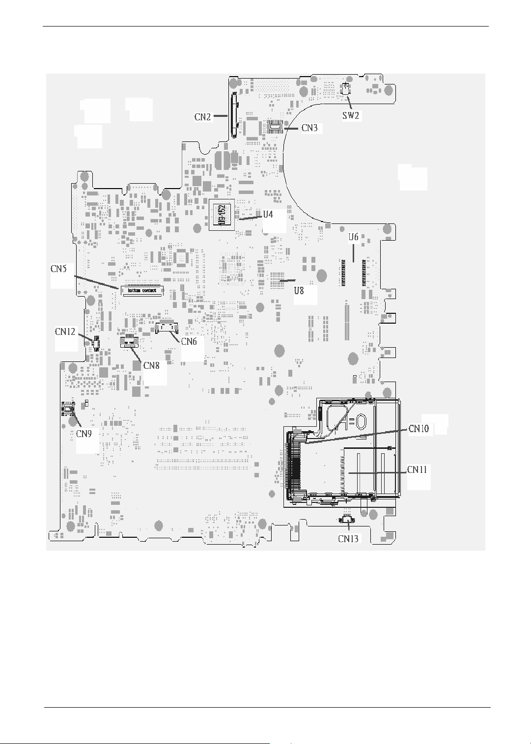
Mainboard Placement
Top View
4 Chapter 1
Rear View
Chapter 1 5

ITEM DESCRIPTION ITEM DESCRIPTION
CN2 LCD Connector CN14 DC JACK
CN3 LED board connector CN15 CRT connector
SW2 Lid switch CN16 Docking connector
CN10 express card connector CN17 Battery connector
CN11 4 IN 1 connector CN18 Fix ODD connector
CN13 Speaker connector CN21 Swap ODD connector
CN9 MD board connector CN24 2nd Battery connector
CN12 INT MIC connector CN30 PATA HDD connector
CN5 Keyboard connector CN31 SATA HDD connector
CN6 BT connector CN36 Line IN connector
CN8 TP connector CN34 MIC IN connector
U4 VGA RAM CN35 Line out/SPDIF
connector
U8 VGA RAM CN33 USB connector
U6 LAN transformer CN32 1394 connector
CN28 PCMCIA connector CN26 USB connector
CN25 USB connector CN23 S video connector
CN20 RJ45/RJ11 connector CN19 Fan connector
CN22 MINI PCI connector U31 CPU
U30 EC U29 VGA Chp
U34 North Bridge U38 South Bridge
U25 VGA RAM U28 VGA RAM
U24 BIOS ROM
6 Chapter 1
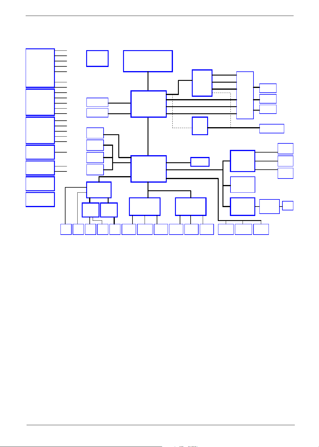
Block Diagram
5VPCU
5V / 3.3V / 12V
Page : 35
1.8V / 0.9V
Page : 36
1.5V / 1.05V / 1.8V
Page : 37
CPU CORE
Page : 34
+1.2V
Page : 38
BATTERY
CHARGER
Page : 39
BATTERY
SELECT
Page : 40
3V_ALWAYS
+12V
+5V
3V_S5
3VSUS
5VSUS
2.5VSUS
+2.5V
+1.8V
MVREF_DM
SMDDR_VTERM
1.5V_S5
+1.5V
AGP_VCC (+1.5V)
1.2VCCT
VTT
VCC_CORE
VGA_CORE
2.5V_VGA
CLOCK GEN
ICS
ICS954201
Page : 2
DDR2-SODIMM1
Page:9~10
DDR2-SODIMM2
Page:9~10
SATA - HDD
Page:21
IDE - HDD
Page:21
IDE-ODD
Page:21
MEDIA BAY
Page:21
AUDIO CODEC
CONEXANT
20468-31
Page:27
MODEM
AMP
CONEXANT
MAX9755
Page:28
20493-21
Page:27
400/533MHZ DDR2
400/533MHZ DDR2
SATA
ATA 66/100
AC97
Centrino
DOTHAN
CELEROM-M
INTEL Mobile_479 CPU
HOST BUS 533MHz
HOST BUS 400MHz
ALVISO
1257 BGA
Page : 5 ~ 8
DMI I/F
ICH6-M
609 BGA
Page : 18 ~ 20
LPC
NS
KBC(97551)
Page : 29
Page : 3 , 4
CRANE2 ( ZL3 )
ATI
PCIE
M26P/M24P
64M /
128M
Page : 11 ~ 14
LVDS
RGB
TVOUT
DVI
CH7307
Page:15
PCIE
PCI BUS
USB 2.0
NEW CARD
Page : 32
NS
SIO (87383)
Page : 31
EXT_LVDS
EXT_CRT
EXT_TV-OUT
INT_LVDS
INT_CRT
INT_TV-OUT
SWITCH
CIRCUIT
TI
PCMCIA+1394
+3 IN 1
PCI7411
Page: 23
MINI-PCI
Wireless LAN
Modem/LAN
Page : 22
BROADCOM
10/100/1G LAN
4401 / 5705M
Page:25
CRT
Page:17
LVDS
Page:16
TV-OUT
Page:16
DOCKING/DVI
Page: 33
BOTHHAND
TRANSFORMER
Page:26
3 IN 1
Page: 24
PCMCIA
Page: 24
1394
Page: 23
RJ45
Page:26
MIC IN
Page:27
LINE
IN
SPEKER
Page:28Page:27
LINE
OUT
Page:28
DOCKING
RJ11
PS2
Page:27
PCI ROUTING TABLE
REQ0# / GNT0#
REQ2# / GNT2#
REQ1# / GNT1#
Page:33
Touchpad
Keyboard
Page:30Page:30
IDSEL
INTERUPT
AD24
INTA#
AD19
INTB# , INTD#
AD17
INTC#,INTD#,INTA#
IrDA
Page:31
DOCKING
Print Port
Page:33
DEVICE
BROADCOM LAN
MINI-PCI
TI 7411
DOCKING
COM Port
Page:33
SYSTEM 3
USB PORT
Page : 22
USB2,3,5
DOCKING 2
USB PORT
Page : 22
USB0,1
MINI-USB
Page: 22
USB4
REV.C
Chapter 1 7
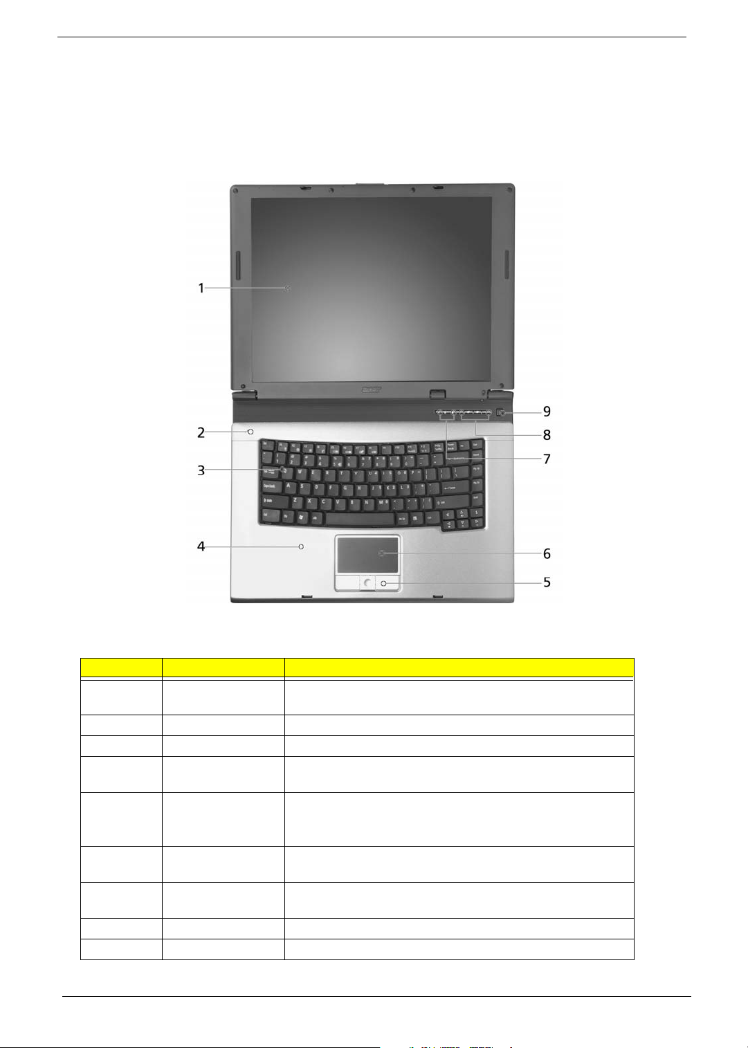
Outlook View
Just for Starters...
A general introduction of ports allow you to connect peripheral devices, as you would with a desktop PC.
Open View
# Item Description
1 Display screen Also called Liquid-Crystal Display (LCD), displaying computer
output.
2 Microphone Internal microphone for sound recording.
3 Keyboard For entering data into your computer.
4 Palmrest Comfortable support area for your hands when you use the
computer.
5 Click buttons
(Left, center and
right)
6 Touchpad Touch-sensitive pointing device which functions like a
7 Status indicators Light-Emitting Diodes (LEDs) that turn on and off to show the
8 Easy-launch buttons Buttons for launching frequently used programs.
9 Power button Turns the computer on and off.
The left and right buttons function like the left and right mouse
buttons; the center button serves as a 4-way scroll button.
computer mouse.
status of the computer’s functions and components.
8 Chapter 1
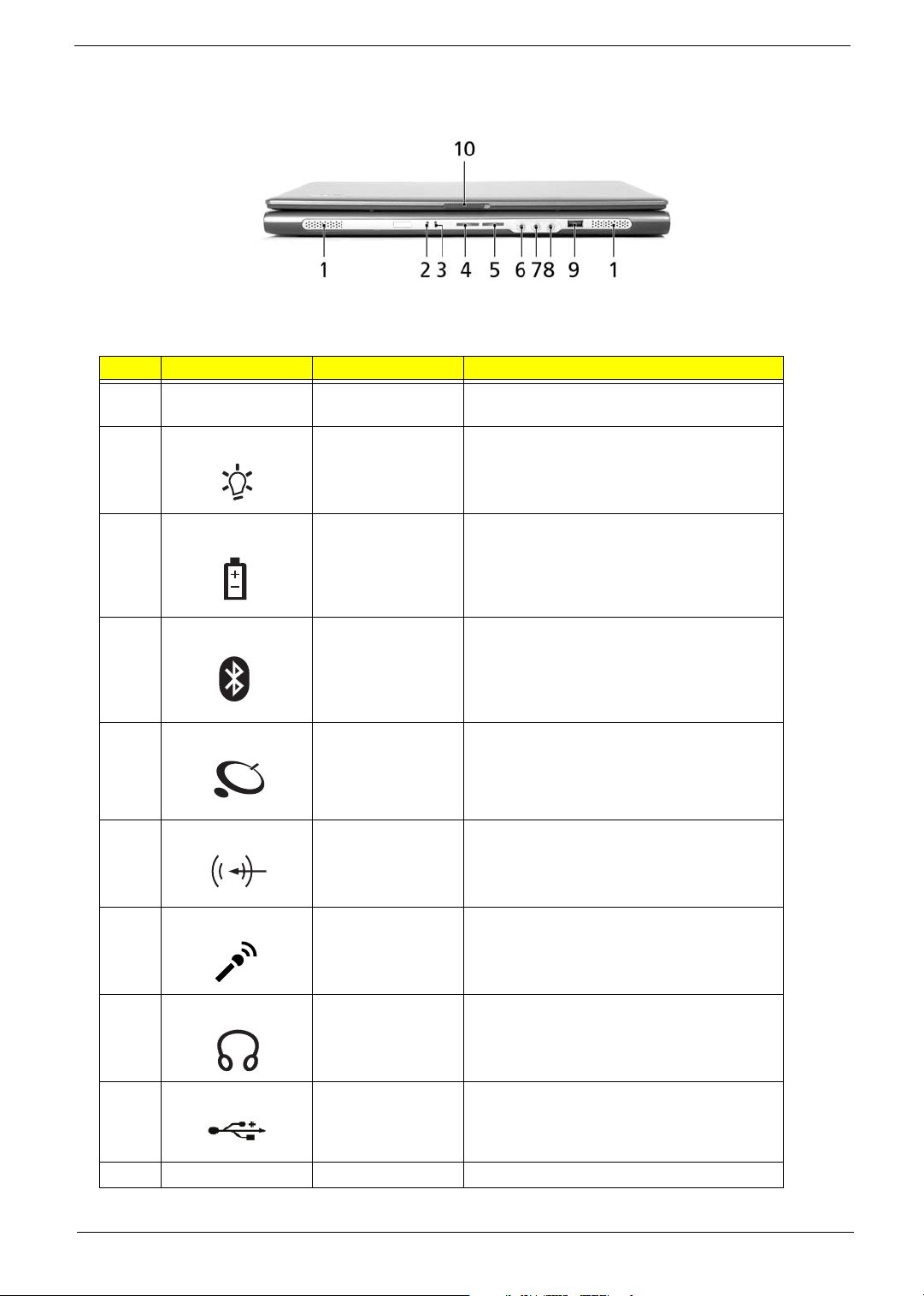
Front Panel
"Launch keys" on page 10
"Launch keys" on page 10
"Launch keys" on page 10
"Launch keys" on page 10
"Launch keys" on page 10
"Launch keys" on page 10
"Launch keys" on page 10
# Icon Item Description
1 Speakers Left and right speakers deliver stereo audio
2 Power indicator Lights when the computer is on.
3 Battery indicator Lights when the battery is being charged.
output.
4 Bluetooth
5Wireless
6 Line-in jack Accepts audio line-in devices (e.g., audio CD
7 Microphone jack Accepts inputs from external microphones.
8 Speaker/Line-Out/
9 USB 2.0 port Connects to Universal Serial Bus (USB) 2.0
communication
button/indicator
communications
button/indicator
Headphone jack
Press to enable/disable Bluetooth function.
Lights to indicate the status of Bluetooth
communications.
Press to enable/disable Wireless function.
Lights to indicate the status of wireless LAN
communications. (manufacturing option)
player, stereo walkman).
Connects to audio line-out devices (e.g.,
speakers, headphones).
devices (e.g., USB mouse, USB camera).
10 Latch Locks and releases the lid.
Chapter 1 9

Left View
# Item Description
1 Optical drive Internal optical drive; accepts CDs or DVDs depending on the
optical drive type.
2 LED indicator Lights up when the optical drive is active.
3 Optical drive eject
button
4 Emergency eject
hole
NOTE: The positions of the AcerMedia indicator, eject button and emergency eject hole may differ depending
on the optical drive module installed.
Ejects the optical drive tray from the drive.
Ejects the optical drive tray when the computer is turned off
10 Chapter 1
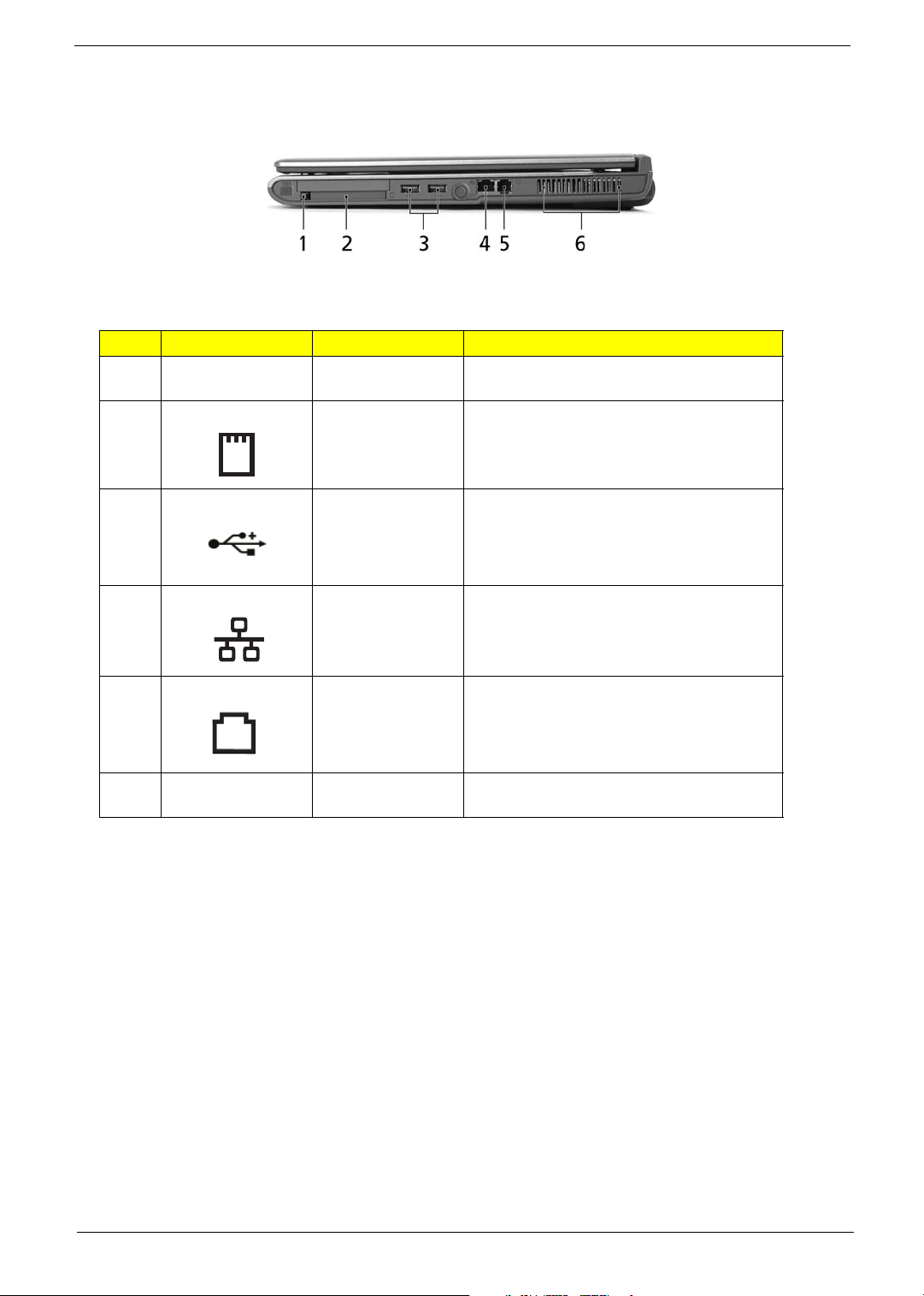
Right View
Note:
Note:
# Icon Item Description
1 PC Card slot eject
button
2 PC Card slot Connects to one Type II CardBus PC Card.
3 Two USB 2.0 ports Connect to Universal Serial Bus (USB) 2.0
Ejects the PC Card from the slot.
devices (e.g., USB mouse, USB camera).
4 Network jack Connects to an Ethernet 10/100/1000-based
network (for selected models).
5 Modem jack Connects to a phone line.
6 Ventilation slots Enable the computer to stay cool, even after
prolonged use.
Chapter 1 11
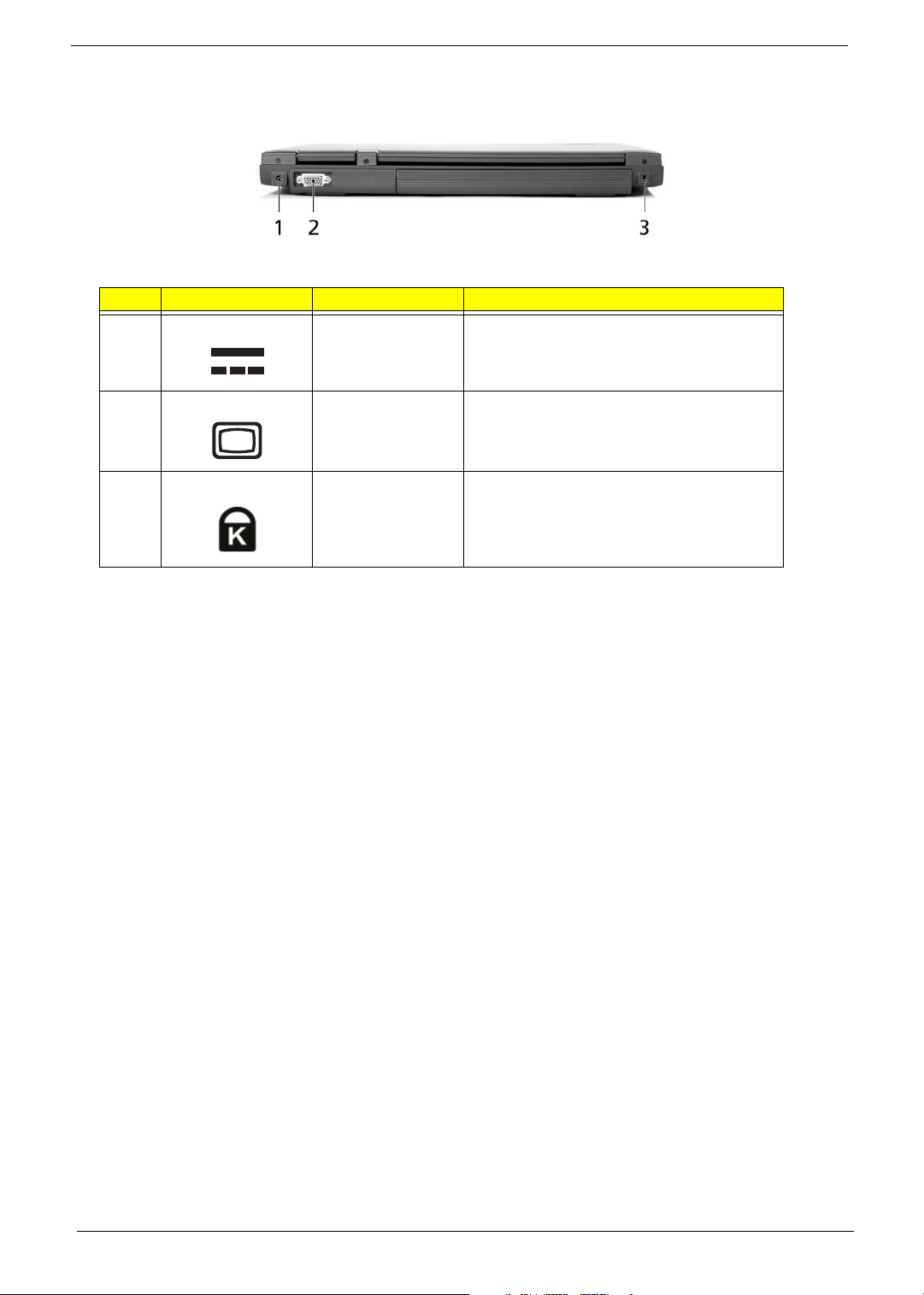
Rear View
Note:
Note:
# Icon Item Description
1 Power jack Connects to an AC adapter.
2 External display port Connects to a display device (e.g., external
monitor, LCD projector).
3 Security keylock Connects to a Kensington-compatible
computer security lock.
12 Chapter 1
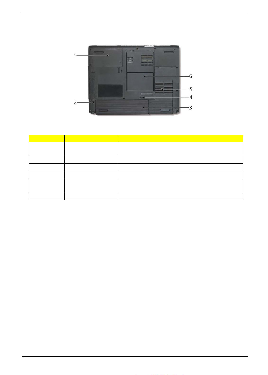
Bottom View
# Item Description
1 Hard disk bay Houses the computer's hard disk
2 Battery release latch Unlatches the battery to remove the battery pack.
3 Battery bay Houses the computer's battery pack.
4 Battery lock Locks the battery in place.
5 Cooling fan Helps keep the computer cool.
6 Memory compartment Houses the computer's main memory and Mini PCI Card.
(secured with two screws).
NOTE: Do not cover or obstruct the opening of the fan.
Chapter 1 13
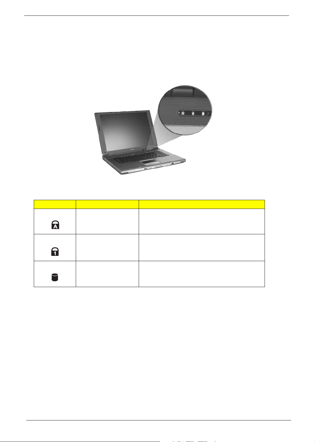
Indicators
Your computer provides an array of three indicators located above the keyboard, in addition to four
indicators positioned at the front of the palm rest area. These indicators show the status of the computer
and its componetns.
The three indicators located above the keyboard provide the following status information:
Icon Item Description
Caps Lock activity Lights when Caps Lock is activated.
Num Lock activiy Lights when Num Lock is activated.
Media activity Lights when the hard disk or optical drive is active.
NOTE: The keypad lock must be turned on to use the embedded numeric keypad.
14 Chapter 1

Easy-launch buttons
The build-in touchpad is a PS/2 compatible pointing device that senses movement on its surface.
The cursor responds to your finger movements on the touchpad. In addition, the two click buttons provide
the same functionality as a computer mouse, while the scroll key enables easy up and down scrolling in
documents and web pages.
The touchpad is located in the middle of the palm rest area, providing maximum comfort and efficiency.
Chapter 1 15
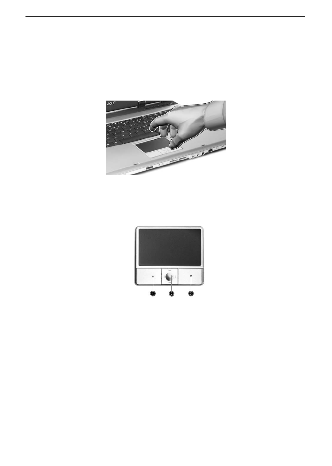
Touchpad
The build-in touchpad is a PS/2 compatible pointing device that senses movement on its surface.
The cursor responds to your finger movements on the touchpad. In addition, the two click buttons provide
the same functionality as a computer mouse, while the scroll key enables easy up and down scrolling in
documents and web pages.
The touchpad is located in the middle of the palm rest area, providing maximum comfort and efficiency.
Touchpad Basics
Use the touchpad as follows:
T Move your finger across the touchpad to move the cursor.
T Press the left (1) and right (3) buttons located on the edge of the touchpad to do selection and
execution functions. These two buttons are similar to the left and right buttons on a mouse.
Tapping on the touchpad is the same as clicking the left button
T Use the 4-way scroll (2) button to scroll up or down and move left or right a page. This button
mimics your cursor pressing on the right scroll bar of windows applications.
16 Chapter 1
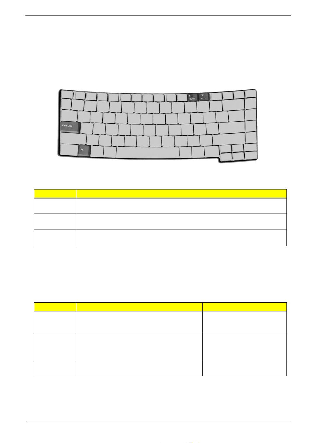
Using the Keyboard
The full-sized keyboard includes an embedded numeric keypad, separate cursor keys, two Windows keys and
twelve function keys.
Lock keys and embedded numeric keypad
The keyboard has four lock keys which you can toggle on and off.
The computer features three lock keys, each with its own status indicator light.
Lock Key Description
Caps Lock When Caps Lock is on, all alphabetic characters are typed in uppercase. Toggle on and
off by pressing the Caps Lock key on the left side of the keyboard.
Num lock
<Fn+F11>
Scroll lock
<Fn+F12>
When Num Lock is on, the embedded numeric keyboard can be used. Toggle on and
off by pressing the Fn+tkeys simultaneously.
When Scroll Lock is on, the screen toggles up or down one line
at a time when the up and down cursor control keys are pressed.
NOTE: Scroll Lock doesn’t work in all applications. Toggle on and off by pressing the Fn+F12 keys
simultaneously.
The embedded numeric keypad functions like a desktop numeric keypad. It is indicated by small characters
located on the upper right corner of the keycaps. To simplify the keyboard legend, cursor-control key symbols
are not printed on the keys.
Desired action Num Lock on Num Lock off
Number keys on
embedded
keypad
Cursor-control
keys on
embedded
keypad
Main keyboard
keys
Type numbers in a normal manner
Hold Shift while using cursor-control keys. Hold Fn while using cursor-control
keys.
Hold Fn while typing letters on embedded keypad. Type the letters in a normal
manner.
Windows Keys
The keyboard features two keys that perform Windows-specific functions.
Chapter 1 17
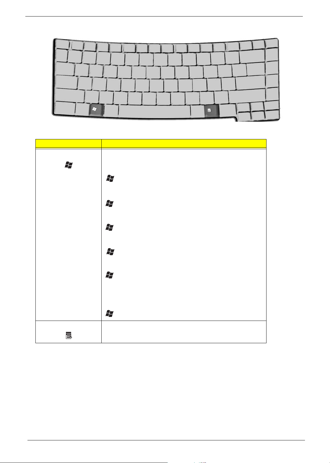
Key Description
yyp p
Windows logo key Pressed alone, this key has the same effect as clicking on the
Windows Start button; it launches the Start menu. It can also be
used with other keys to provide a variety of functions:
+ Tab (Activates the next Taskbar button)
+ E (Opens the My Computer window)
+ F1 (opens Help and Support)
+ F (opens the Find: All Files dialog box)
+ M (minimizes all windows)
j + Windows icon + M (undoes the minimize all windows
action)
+ R (opens the Run dialog box)
Application key This key has the same effect as clicking the right mouse button; it
opens the application’s context menu.
Hot Keys
The computer employs hot keys or key combinations to access most of the computer’s controls like screen
brightness, volume output and the BIOS Utility.
To activate hot keys, press and hold the <Fn> key before pressing the other key in the hot key combination.
18 Chapter 1

Your computer provides the following hot keys:
Fn
Hot Key Function Description
Fn-F1 Hot key help Displays help on hot keys.
Fn-F2 eSetting Launches the eSetting in the
Fn-F3 ePowerManagement (ePM) Launches the ePowerManagement in the eManager
set by the Acer Empowering Key “e”
Fn-F4 Sleep Puts the computer in Sleep mode.
Fn-F5 Display toggle Switches display output between the display screen,
external monitor (if connected) and both the display
screen and external monitor.
Fn-F6 Screen blank Turns the display screen backlight off to save power.
Press any key to return.
Fn-F7 Touchpad toggle Turns the internal touchpad on and off.
Fn-F8 Speaker toggle Turns the speakers on and off
Fn+w Volume up Increases the speaker volume.
Fn+y Volume down Decreases the speaker volume.
Fn+x Brightness up Increases the screen brightness.
Fn+z Brightness down Decreases the screen brightness.
NOTE: When activating hotkeys, press and hold the Fn key before pressing the other key in the hotkey
combination.
Special Keys
You can locate the Euro symbol and US dollar sign at the upper-centerand/or bottom-right of your keyboard.
To t y pe :
Chapter 1 19

The Euro symbol
1. Open a text editor or word processor.
2. Either directly press the Euro symbol at the bottom-right of the keyboard, or hold Alt Gr and then press
the Euro symbol at the upper-center of the keyboard.
The US dollar sign
1. Open a text editor or word processor.
2. Either directly press the dollar sign at the bottom-right of the keyboard, or hold Shift and then press the
dollar sign at the upper-center of the keyboard.
20 Chapter 1
Using System Utilities
“Launch keys” on page 20
Acer eSetting
“Launch keys” on page 20
Acer eSetting
Acer ePresentation
“Launch keys” on page 20
Acer eSetting
Acer ePresentation
Acer ePowerManagement
“Launch keys” on page 20
Acer eSetting
Acer ePresentation
Acer ePowerManagement
Acer eRecovery
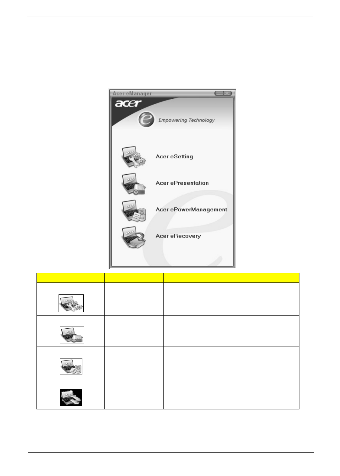
Acer eManager
Innovative Acer eManagement software is designed for easy access to frequently used functions. At the press
of Acer Empowering Key, the Acer eManager user interface appears, featuring four main settings -- Acer
eSetting, Acer ePresentation, Acer ePowerManagement and Acer eRecovery.
Icon Item Description
Acer eSetting It is an easy way to manage the settings and security
of your PC.
Acer ePresentation It takes the hassle out of making presentations.
Acer
ePowerManagement
Chapter 1 21
Acer eRecovery It backs up your files preventing data loss in the
It provides a central location from where to control all
your PC’s power schemes and maximise battery life.
event of a system crash.
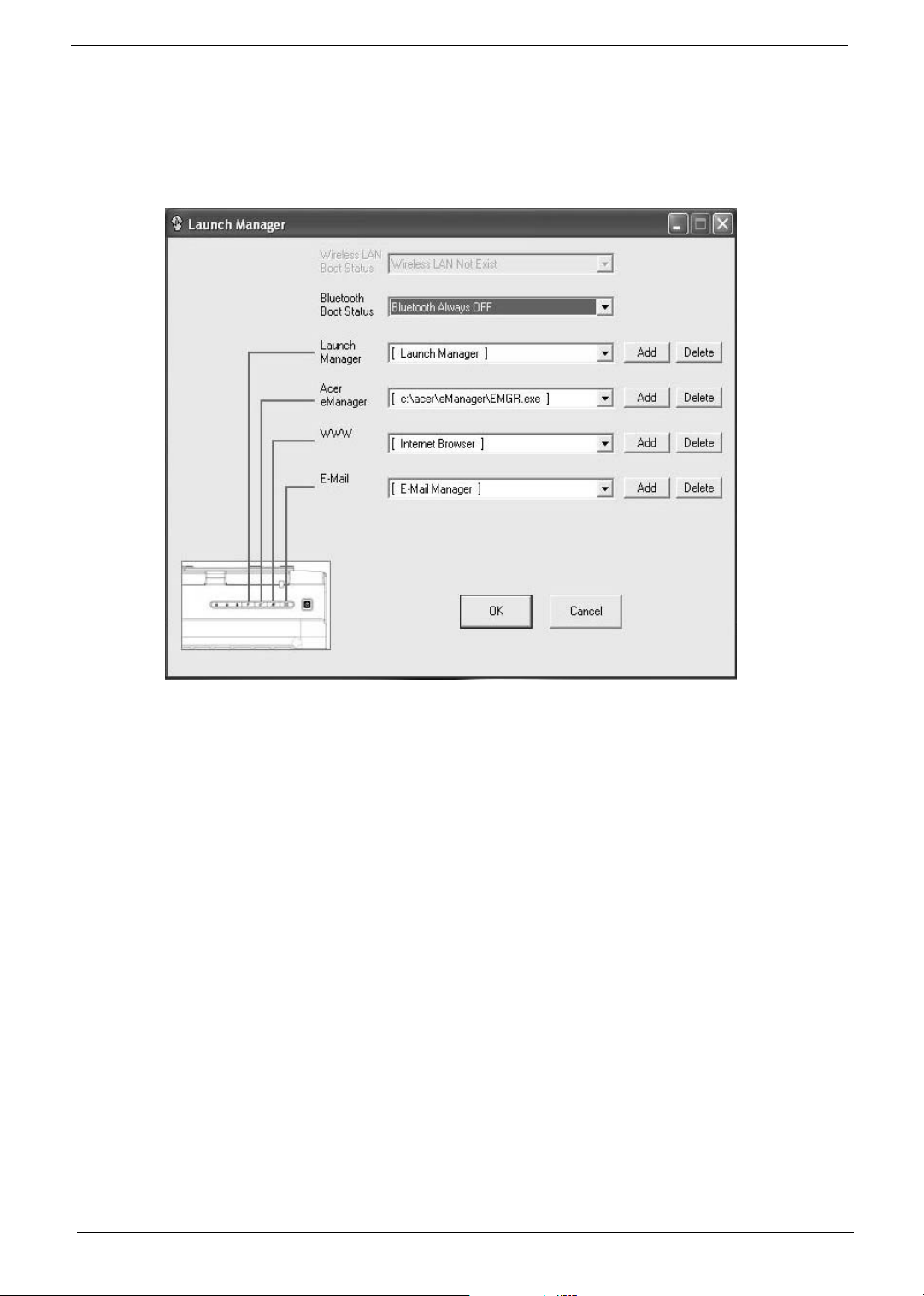
Launch Manager
Start
Launch Manager allows you to set the two launch keys located above the keyboard.
You can access the Launch Manager by clicking on Start, All Programs, and then Launch Manager to start
the application.
22 Chapter 1

Hardware Specifications and Configurations
Processor
Item Specification
CPU type
CPU package uFPGA 478
CPU core voltage Depend on DVI
CPU I/O voltage 1.2V
System Board Major Chips
Item Controller
System core logic
Super I/O controller KBC (97551), LPC interface
Audio controller Conexant Codec
Video controller ATI M24P
Hard disk drive controller ICH6-M
Keyboard controller KBC 97551
IrDA controller SIO 87383
DVI controller CH7307
PCMCIA/ card reader / 1394
controller
DDR-soDIMM controller 915PM/915GM
®
Pentium® M Processor at 1.5 ~2.13 GHz or higher
Intel
®
Celeron® M Processor at 1.3~1.5 GHz or higher
Intel
®
915PM / ICH6-M
Intel
®
Intel
915GM / ICH6-M
UMA
TI PCI7411
BIOS
Item Specification
BIOS vendor Phoenix
BIOS Version Phoenix First BIOS
BIOS ROM type Flash ROM
BIOS ROM size 512KB
BIOS package 32 lead of TSSOP
BIOS password control Set by setup manual
L2 Cache
Item
Cache controller Built-in CPU
Cache size 2 MB
1st level cache control Always enabled
2nd level cache control Always enabled
Cache scheme control Always enabled
Chapter 1 23
System Memory
Item Specification
Memory controller 915PM/915GM
Memory size 256MB/512MB
DIMM socket number 2
Supports memory size per slot 1024 MB
Supports maximum memory size 2GB
Supports DIMM type DDRII SDRAM standard
Supports DIMM Speed 400/533 MHz
Supports DIMM voltage 1.8V
Memory module combinations You can install memory modules in any combinations as long as
they match the above specifications.
.
LAN Interface
Item Specification
Supports LAN protocol 10/100 Mbps Fast Ethernet connection
LAN connector type RJ45
Wireless LAN InviLink. 802.11b/g dual-band tri-mode Wireless
or 802.11 a/b/g dual-band tri-mode Wireless
LAN connector location Right side
.
Modem/Bluetooth Interface
Item Specification
Data modem data baud rate (bps) 56K ITU
Supports modem/bluetooth
protocol
V.90/V.92 AC-Link modem with PTT approval
Wake-on-Ring ready
Modem connector type RJ11
Modem connector location Right side
VGA
Notice Discrete UMA
Chipset for suitable VGA type Intel (R) 915PM Intel (R) 915GM
USB Port
Item Specification
USB compliancy level 2.0
OHCI USB 2.0
Number of USB port 3
Location Right Side *2
Front Side *1
24 Chapter 1
 Loading...