

Page 1
AcerPower Sx/Sxb/Sc
Service Guide
Service guide files and updates are available
on the AIPG/CSD web; for more information,
please refer to http://csd.acer.com.tw
PART NO.: 49.39J03.001
DOC. NO.: SG3410003A PRINTED IN TAIWA N
Page 2
Revision History
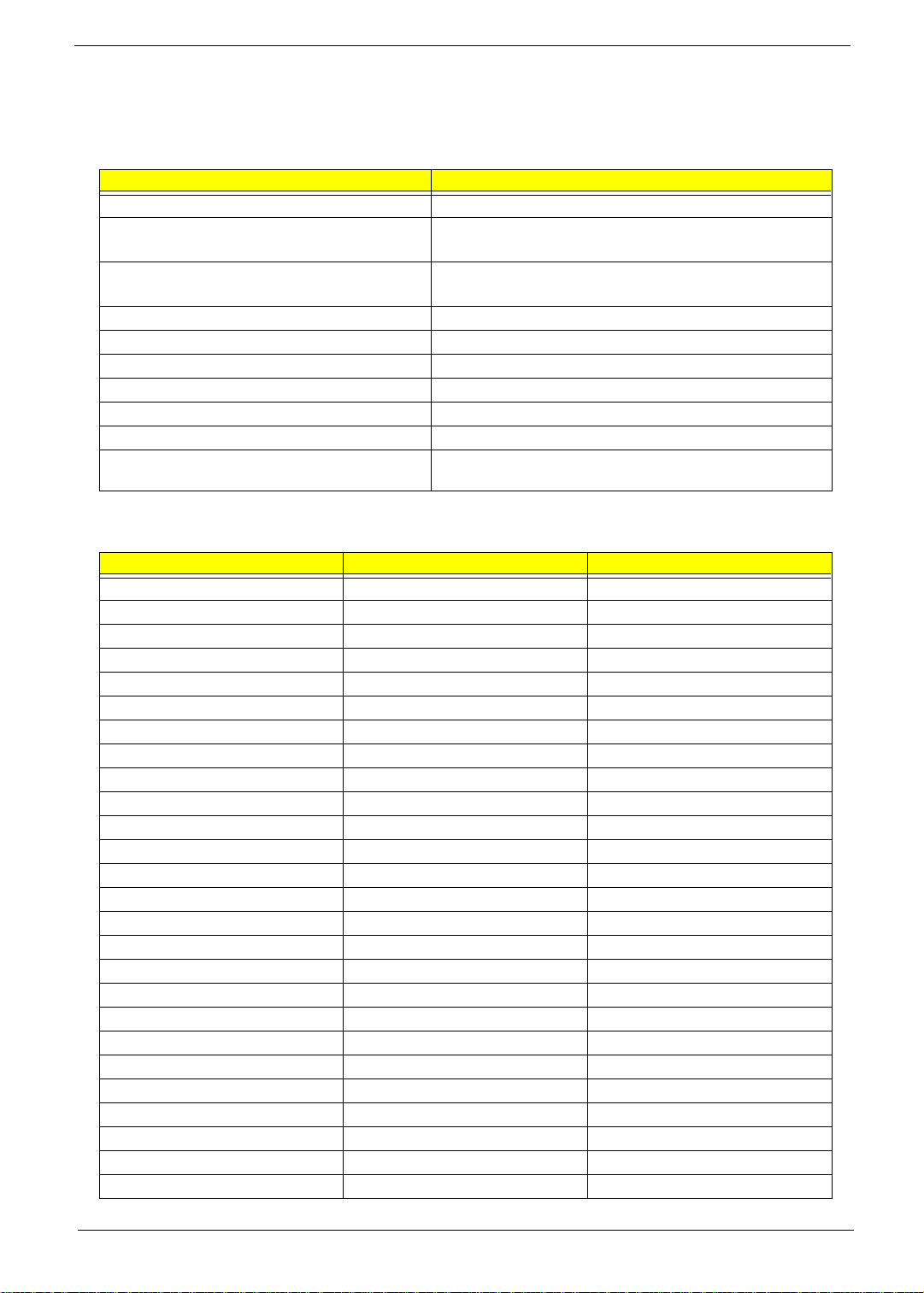
Please refer to the table below for the updates made on AcerPower SX service guide.
Date Chapter Updates
01/11/2001 Chapter 5 Add CN4, SW1 and JP11
01/20/2001 Chapter 1&6 Indicate the the Part nos. of mainboard that supports LAN
function.
02/09/2001 Appendix B Add a NOTE below the table of SCO UNIX/Linux
Environment Test section.
03/23/2001 Chapter 4 Add troubleshooting information.
05/29/2001 Cover
Chapter 2
Chapter 5
07/16/2001 Chapter 5 Add a note under the table for Socket 370 core/bus clock
10/26/2001 Chapter 1, Chapter 5, AppA,
Cover
Add AcerPower Sxb on the top cover.
“Product Information” and “Onboard Perpherals” BIOS
screen were added for AcerPower Sxb model.
Add a NOTE indicating the part number used by AcerPower
Sx and AcerPower Sxb mainboard.
ratio.
For AcerPower Sc:
Add system features, Mainboard
Jumpers and Connectors
Model Definition
II
Page 3

Copyright
Copyright © 2001 by Acer Incorporated. All rights reserved. No part of this publication may be reproduced,
transmitted, transcribed, stored in a retrieval system, or translated into any language or computer language, in
any form or by any means, electronic, mechanical, magnetic, optical, chemical, manual or otherwise, without
the prior written permission of Acer Incorporated.
Disclaimer
The information in this guide is subject to change without notice.
Acer Incorporated makes no representations or warranties, either expressed or implied, with respect to the
contents hereof and specifically disclaims any warranties of merchantability or fitness for any particular
purpose. Any Acer Incorporated software described in this manual is sold or licensed "as is". Should the
programs prove defective following their purchase, the buyer (and not Acer Incorporated, its distributor, or its
dealer) assumes the entire cost of all necessary servicing, repair, and any incidental or consequential
damages resulting from any defect in the software.
Acer is a registered trademark of Acer Corporation.
Intel is a registered trademark of Intel Corporation.
Pentium and Pentium II/III are trademarks of Intel Corporation.
Other brand and product names are trademarks and/or registered trademarks of their respective holders.
III
Page 4

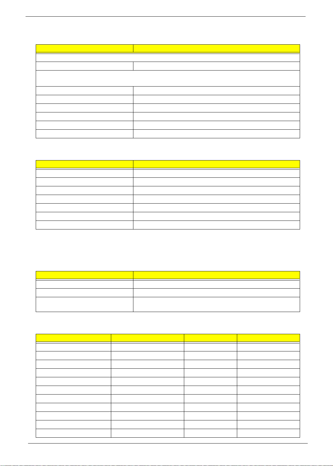
Conventions
The following conventions are used in this manual:
Screen messages Denotes actual messages that appear
on screen.
NOTE
WARNING
CAUTION
IMPORTANT
Gives bits and pieces of additional
information related to the current
topic.
Alerts you to any damage that might
result from doing or not doing specific
actions.
Gives precautionary measures to
avoid possible hardware or software
problems.
Reminds you to do specific actions
relevant to the accomplishment of
procedures.
IV
Page 5

Preface
Before using this information and the product it supports, please read the following general information.
1.
This Service Guide provides you with all technical information relating to the BASIC CONFIGURATION
decided for Acer's "global" product offering. To better fit local market requirements and enhance product
competitiveness, your regional office MAY have decided to extend the functionality of a machine (e.g.
add-on card, modem, or extra memory capability). These LOCALIZED FEATURES will NOT be covered
in this generic service guide. In such cases, please contact your regional offices or the responsible
personnel/channel to provide you with further technical details.
2.
Please note WHEN ORDERING FRU PARTS, that you should check the most up-to-date information
available on your regional web or channel. If, for whatever reason, a part number change is made, it will
not be noted in the printed Service Guide. For ACER-AUTHORIZED SERVICE PROVIDERS, your Acer
office may have a DIFFERENT part number code to those given in the FRU list of this printed Service
Guide. You MUST use the list provided by your regional Acer office to order FRU parts for repair and
service of customer machines.
V
Page 6

VI
Page 7

Table of Contents
Chapter 1 System Specifications 1
AcerPower Sx Features . . . . . . . . . . . . . . . . . . . . . . . . . . . . . . . . . . . . . . . . . . . .2
AcerPower Sc Features . . . . . . . . . . . . . . . . . . . . . . . . . . . . . . . . . . . . . . . . . . . .3
Front Panel . . . . . . . . . . . . . . . . . . . . . . . . . . . . . . . . . . . . . . . . . . . . . . . . . . . . . .4
Rear Panel . . . . . . . . . . . . . . . . . . . . . . . . . . . . . . . . . . . . . . . . . . . . . . . . . . . . . .5
AcerPower Sx Main Board Layout . . . . . . . . . . . . . . . . . . . . . . . . . . . . . . . . . . . .6
AcerPower Sc Main Board Layout . . . . . . . . . . . . . . . . . . . . . . . . . . . . . . . . . . . .8
Keyboard . . . . . . . . . . . . . . . . . . . . . . . . . . . . . . . . . . . . . . . . . . . . . . . . . . . . . . .9
Cursor keys . . . . . . . . . . . . . . . . . . . . . . . . . . . . . . . . . . . . . . . . . . . . . . . . . .9
Lock keys . . . . . . . . . . . . . . . . . . . . . . . . . . . . . . . . . . . . . . . . . . . . . . . . . . .9
Windows keys . . . . . . . . . . . . . . . . . . . . . . . . . . . . . . . . . . . . . . . . . . . . . . .10
Hardware Specifications and Configurations . . . . . . . . . . . . . . . . . . . . . . . . . . .11
Power Management Function (ACPI support function) . . . . . . . . . . . . . . . . . . .21
Chapter 2 System Utilities 23
Entering Setup . . . . . . . . . . . . . . . . . . . . . . . . . . . . . . . . . . . . . . . . . . . . . . . . . .24
System Information . . . . . . . . . . . . . . . . . . . . . . . . . . . . . . . . . . . . . . . . . . . . . . .26
Product Information . . . . . . . . . . . . . . . . . . . . . . . . . . . . . . . . . . . . . . . . . . . . . .28
Disk Drives . . . . . . . . . . . . . . . . . . . . . . . . . . . . . . . . . . . . . . . . . . . . . . . . . . . . .30
IDE Primary/Secondary Channel Master/Slave . . . . . . . . . . . . . . . . . . . . .31
Onboard Peripherals . . . . . . . . . . . . . . . . . . . . . . . . . . . . . . . . . . . . . . . . . . . . . .33
Power Management . . . . . . . . . . . . . . . . . . . . . . . . . . . . . . . . . . . . . . . . . . . . . .36
Boot Options . . . . . . . . . . . . . . . . . . . . . . . . . . . . . . . . . . . . . . . . . . . . . . . . . . . .38
Date and Time . . . . . . . . . . . . . . . . . . . . . . . . . . . . . . . . . . . . . . . . . . . . . . . . . .39
System Security . . . . . . . . . . . . . . . . . . . . . . . . . . . . . . . . . . . . . . . . . . . . . . . . .40
Setting a Password . . . . . . . . . . . . . . . . . . . . . . . . . . . . . . . . . . . . . . . . . . .41
Changing or Removing the Password . . . . . . . . . . . . . . . . . . . . . . . . . . . .42
Bypassing the Password . . . . . . . . . . . . . . . . . . . . . . . . . . . . . . . . . . . . . . .42
Advanced Options . . . . . . . . . . . . . . . . . . . . . . . . . . . . . . . . . . . . . . . . . . . . . . .43
Memory/Cache Options . . . . . . . . . . . . . . . . . . . . . . . . . . . . . . . . . . . . . . .43
PnP/PCI Options . . . . . . . . . . . . . . . . . . . . . . . . . . . . . . . . . . . . . . . . . . . . .45
Chipset Settings . . . . . . . . . . . . . . . . . . . . . . . . . . . . . . . . . . . . . . . . . . . . .46
Load Default Settings . . . . . . . . . . . . . . . . . . . . . . . . . . . . . . . . . . . . . . . . . . . . .47
Abort Settings Change . . . . . . . . . . . . . . . . . . . . . . . . . . . . . . . . . . . . . . . . . . . .48
Exiting Setup . . . . . . . . . . . . . . . . . . . . . . . . . . . . . . . . . . . . . . . . . . . . . . . . . . . .49
Chapter 3 Machine Disassembly and Replacement 51
Removing a DIMM . . . . . . . . . . . . . . . . . . . . . . . . . . . . . . . . . . . . . . . . . . . . . . .52
Removing the CPU Fan-sink and CPU Board . . . . . . . . . . . . . . . . . . . . . . . . . .53
Opening the Housing . . . . . . . . . . . . . . . . . . . . . . . . . . . . . . . . . . . . . . . . . . . . .55
Removing an Expansion Board . . . . . . . . . . . . . . . . . . . . . . . . . . . . . . . . . . . . .56
Removing a 3.5-inch Drive . . . . . . . . . . . . . . . . . . . . . . . . . . . . . . . . . . . . . . . . . 57
Removing a 5.25-inch Drive . . . . . . . . . . . . . . . . . . . . . . . . . . . . . . . . . . . . . . . .59
Removing the Main board . . . . . . . . . . . . . . . . . . . . . . . . . . . . . . . . . . . . . . . . . .60
Removing a Daughterboard . . . . . . . . . . . . . . . . . . . . . . . . . . . . . . . . . . . . . . . .61
Chapter 4 Troubleshooting 63
Power-On Self-Test (POST) . . . . . . . . . . . . . . . . . . . . . . . . . . . . . . . . . . . . . . . .64
POST Check Points . . . . . . . . . . . . . . . . . . . . . . . . . . . . . . . . . . . . . . . . . . . . . .65
POST Error Messages List . . . . . . . . . . . . . . . . . . . . . . . . . . . . . . . . . . . . . . . . .68
Error Symptoms List . . . . . . . . . . . . . . . . . . . . . . . . . . . . . . . . . . . . . . . . . . . . . .70
Error Beep Definition . . . . . . . . . . . . . . . . . . . . . . . . . . . . . . . . . . . . . . . . . . . . .74
Boot Block Update Function Error Beep Definition . . . . . . . . . . . . . . . . . . . . . . . 75
Undetermined Problems . . . . . . . . . . . . . . . . . . . . . . . . . . . . . . . . . . . . . . . . . . .76
VII
Page 8

Table of Contents
Chapter 5 Jumper and Connector Information 77
AcerPower Sx/Sxb Jumpers and Connectors . . . . . . . . . . . . . . . . . . . . . . . . . . .77
Connector Description . . . . . . . . . . . . . . . . . . . . . . . . . . . . . . . . . . . . . . . .78
AcerPower Sc Jumpers and Connectors . . . . . . . . . . . . . . . . . . . . . . . . . . . . . .79
Connector Description . . . . . . . . . . . . . . . . . . . . . . . . . . . . . . . . . . . . . . . .80
Chapter 6 FRU (Field Replaceable Unit) List 81
Appendix A Model Definition and Configuration 91
Appendix B Test Compatible Components 93
Microsoft DOS V6.22 Environment Test . . . . . . . . . . . . . . . . . . . . . . . . . . . . . . .94
Microsoft Windows 98 SE (En/TC/SC) Environment Test . . . . . . . . . . . . . . . . . 95
Microsoft Windows 2000 Environment Test . . . . . . . . . . . . . . . . . . . . . . . . . . . .97
Microsoft Windows NT 4.0 Environment Test . . . . . . . . . . . . . . . . . . . . . . . . . . .98
IBM OS/2 Warp 4.0 Environment Test . . . . . . . . . . . . . . . . . . . . . . . . . . . . . . . .99
Novell Netware 3.12, 4.11 & 5.0 Environment Test . . . . . . . . . . . . . . . . . . . . .100
SCO UNIX/Linux Environment Test . . . . . . . . . . . . . . . . . . . . . . . . . . . . . . . . .101
Appendix C Online Support Information 103
Index 105
VIII
Page 9

System Specifications
Overview
The AcerPower Sx is an Intel Pentium III or Cyrix III processor with socket-370 based micro-ATX, IBM PC/AT
compatible system with LPC/PCI bus.
Chapter 1
Chapter 1 1
Page 10

AcerPower Sx Features
Performance
Intel Pentium® III, Celeron or Cyrix III processor with integrated L2 cache memory running at 500,
!
550 and 600 MHz or 533, 667, 733 MHz.
Two Dual in-line memory module (DIMM) sockets that accept 32, 64, 128 and 256MB,
!
168-pin DIMM modules, allowing memory upgrade of up to 512 MB
Power management function (Support for APM-1.2 for Non-ACPI Implementations, ACPI 1.0
!
compliant)
Plug-and Play (PnP) feature
!
On-board PCI master enhanced local bus IDE
!
Models with Part No. 55.39J01.M03 can support 10/100M LAN (Embedded in SiS630 chipset),
!
while some models with Part No. 55.39J01.M06 will not support LAN even though chipsets are still
present on the mainboard.
PS/2 mouse and keyboard interface
!
Low Pin Count (LPC) I/F
!
3 PCI slots + 2 DIMM slots
!
Software shutdown for Windows 95/98
!
Hardware Monitor function (only support SMB bus)
!
On-board FDD interface-360K/720K/1.2MB/1.44MB/2.88MB & 3 mode FDD
!
Multimedia
On-board Audio with AC’97/98 compliant (Embedded in SiS630 chipset)
!
Line-in, Line-out, Mic-in, and Game/MIDI interfaces
!
Connectivity
On-board serial ports-2 high speed NS16C550 compatible UARTs with 16 byte FIFOs
!
On-board parallel port-SPP, EPP and ECP (IEEE 1284 compliant)
!
Universal Serial Bus (USB) ports
!
External VGA port for simultaneous LCD and PRT display support
!
High-speed fax/data PCI modem
!
Human-centric design and ergonomics
Slim, smooth and stylish design
!
2 Chapter 1
Page 11

AcerPower Sc Features
Performance
Intel Tualatin Pentium® III, Celeron Pocessor with integrated L2 cache memory running from
!
1.1GHz to 1.4 GHz.
Dual in-line memory module (DIMM) sockets that accept 128MB, 256MB, and 512MB.
!
168-pin DIMM modules, allowing memory upgrade of up to 1GB
!
Power management function (Support for ACPI compliant)
!
Plug-and Play (PnP) feature
!
On-board PCI master enhanced local bus IDE
!
Built-in SiS900 10/100BASE-T Ethernet controller (RJ-45 connector)
!
USB mouse and keyboard interface
!
Low Pin Count (LPC) I/F
!
3 PCI slots + 2 DIMM slots
!
! Software shutdown for Windows 98se/ME/2K/XP
On-board FDD interface-360K/720K/1.2MB/1.44MB/2.88MB & 3 mode FDD
!
Multimedia
On-board Audio with AC’97 CODEC with 16-pin CD-quality stereo output (On Die Controller
!
SiS 630ET chipset).
Stereo Input and output , mono microphone input interfaces
!
Connectivity
On-board serial port- One high speed NS16C550 compatible UARTs with 16 byte FIFOs
!
On-board parallel port- EPP, ECP, and IEEE 1284
!
Mini-DIN PS/2 keyboard and mouse ports
!
4 Universal Serial Bus (USB) ports
!
High-speed fax/data PCI modem
!
Human-centric design and ergonomics
Slim, smooth and stylish design
!
Chapter 1 3
Page 12

Front Panel
The computer’s front panel consists of the following:
Label Description
1 Headphone/Earphone port
2 CD-ROM tray
3 Stop/Eject button
4 Skip/Forward button
5 CD-ROM LED
6 Increase volume button
7 Decrease volume button
8 Turbo LED
9 Power LED
10 Hard disk drive LED
11 Po wer b u t ton
12 3.5-inch floppy disk drive eject button
13 3.5-inch floppy disk drive
14 3.5-inch floppy disk drive LED
4 Chapter 1
Page 13
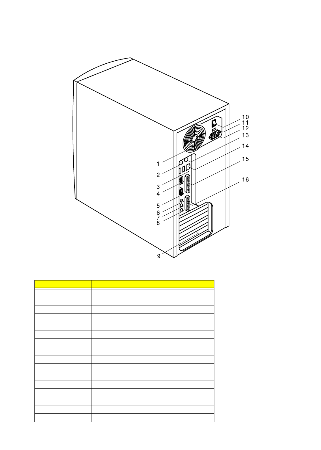
Rear Panel
The computer’s rear panel consists of the following:
Label Description
1Fan
2 PS/2 keyboard port
3 USB ports
4 Serial port
5 VGA/Monitor port
6 Speaker-out/Line-out port
7Line-in port
8 Microphone-in port
9 Add-on brackets
10 System main power switch
11 Voltage selector
12 System power socket
13 PS/2 mouse port
14 LAN port
15 Parallel port
16 Game/MIDI port
Chapter 1 5
Page 14
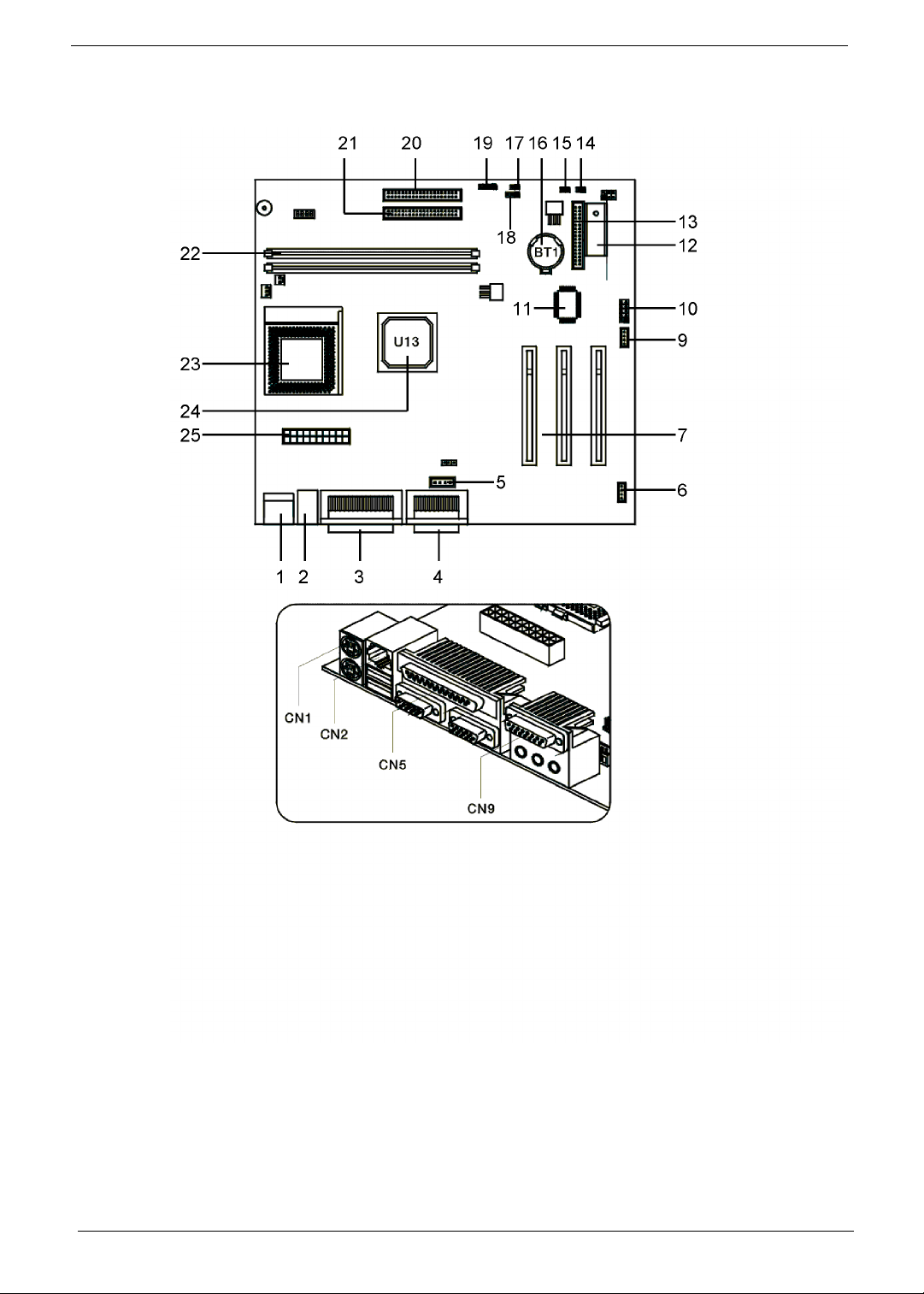
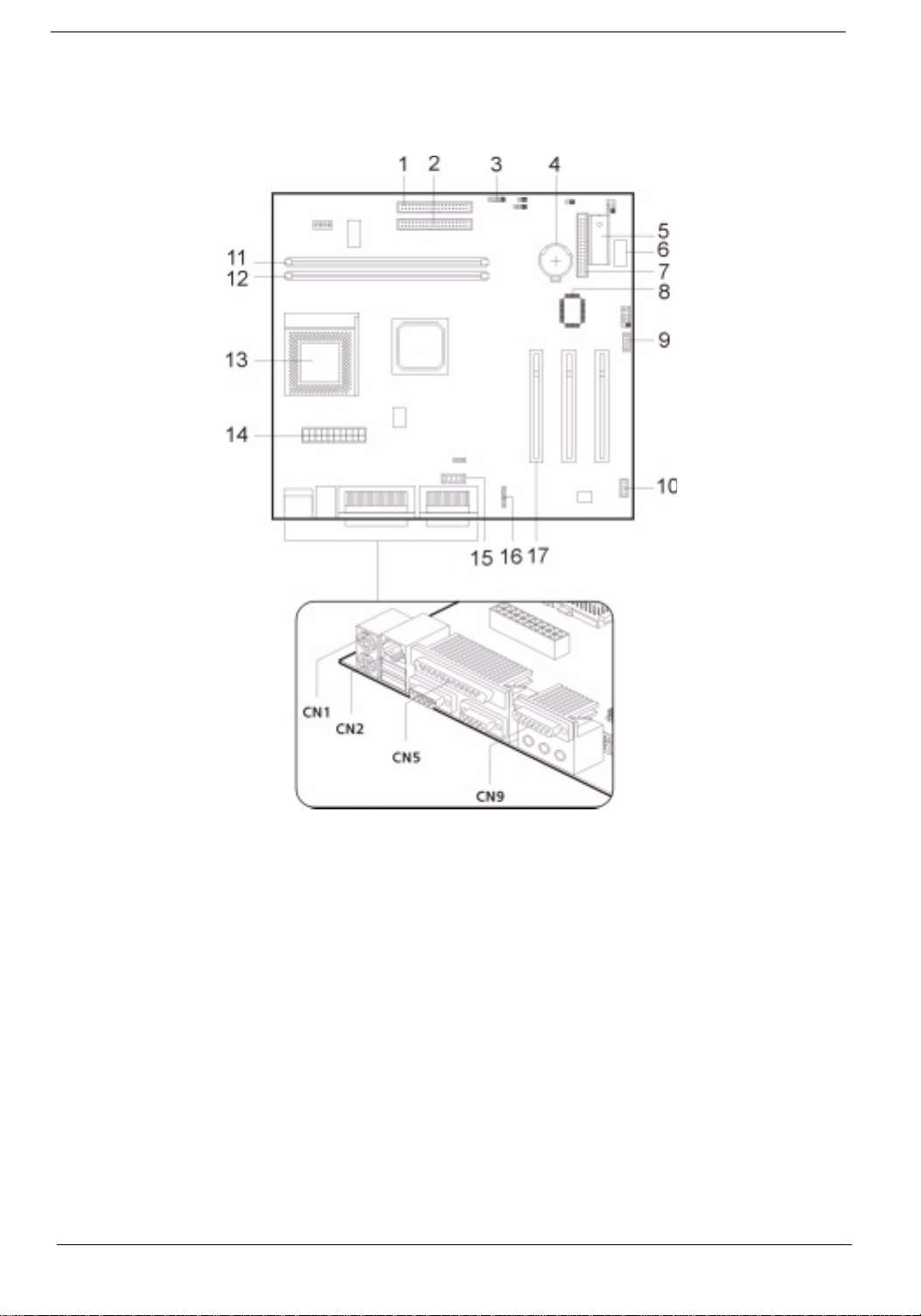
AcerPower Sx Main Board Layout
6 Chapter 1
Page 15

1. PS/2 keyboard and mouse port 14. Reset
2. USB/LAN port 15. Power Switch
3. Parallel/VGA/serial port 2 16. Battery
4. Game/MIDI port 17. LAN/LED
5. Audio/CD connector 18. Power LED
6. Fax/voice modem connector 19. Hard Disk Drive LED connector
7. PCI slots (three slots) 20. IDE 1 connector
9. Wake on LAN connector 21. IDE 2 connector
10. Serial port 1 22. DIMM sockets (two sockets)
11. SiS950 chipset 23. CPU socket
12. BIOS chipset 24. SiS630 chipset
13. Floppy disk drive connector 25. ATX power connector
NOTE: 8 was for AGP slot, removed when ship out
Chapter 1 7
Page 16
AcerPower Sc Main Board Layout
1. IDE 1 connector 10. Fax voice modem connector
2. IDE 2 connector 11. DIMM sockets
3. Hard Disk Drive LED connector 12. CPU socket
4. RTC Battery 13. ATX power connector
5. ROM 14. Audio/CD connector
6. Optional USB ports 15. Audio-in connector
7. Floppy disk drive connector 16. PCI sockets (three slots)
8. SiS950 chipset 17. PS/2 keyboard and mouse port
9. Wake on LAN connector
8 Chapter 1
Page 17
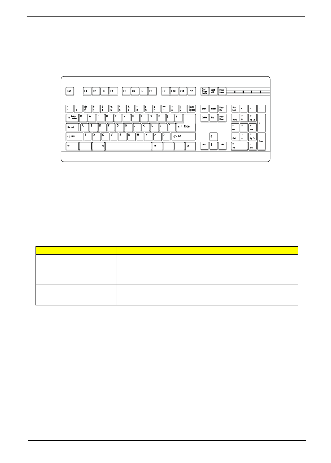
Keyboard
The keyboard has full-sized keys that include separate cursor keys, two Windows keys, and twelve function
keys.
Cursor keys
The cursor keys, also called the arrow keys, let you move the cursor around the screen. They serve the same
function as the arrow keys on the numeric keypad when the Num Lock is toggled off.
Lock keys
The keyboard has three lock keys which you can toggle on and off to switch between two functions.
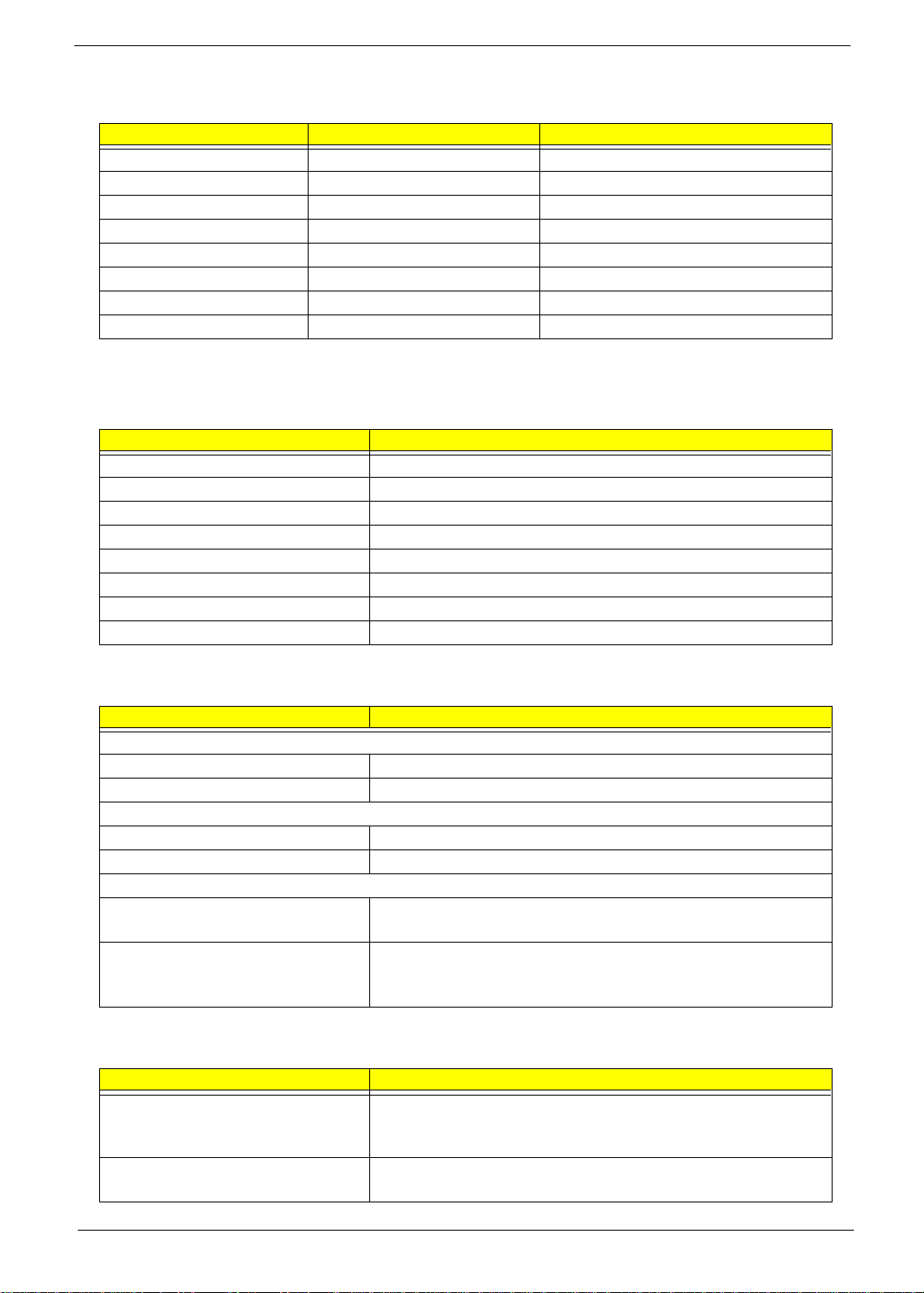
Lock Key Description
Caps Lock When activated, all alphabetic characters typed appear in uppercase (same
function as pressing
Num Lock When activated, the keypad is set to numeric mode, i.e., the keys will function as a
calculator (complete with arithmetic operators such as +, -, x, and /).
Scroll Lock When activated, the screen moves one line up or down when you press the up
arrow or down arrow respectively. Take note that Scroll Lock may not work with
some applications.
Shift
+ <letter>).
Chapter 1 9
Page 18
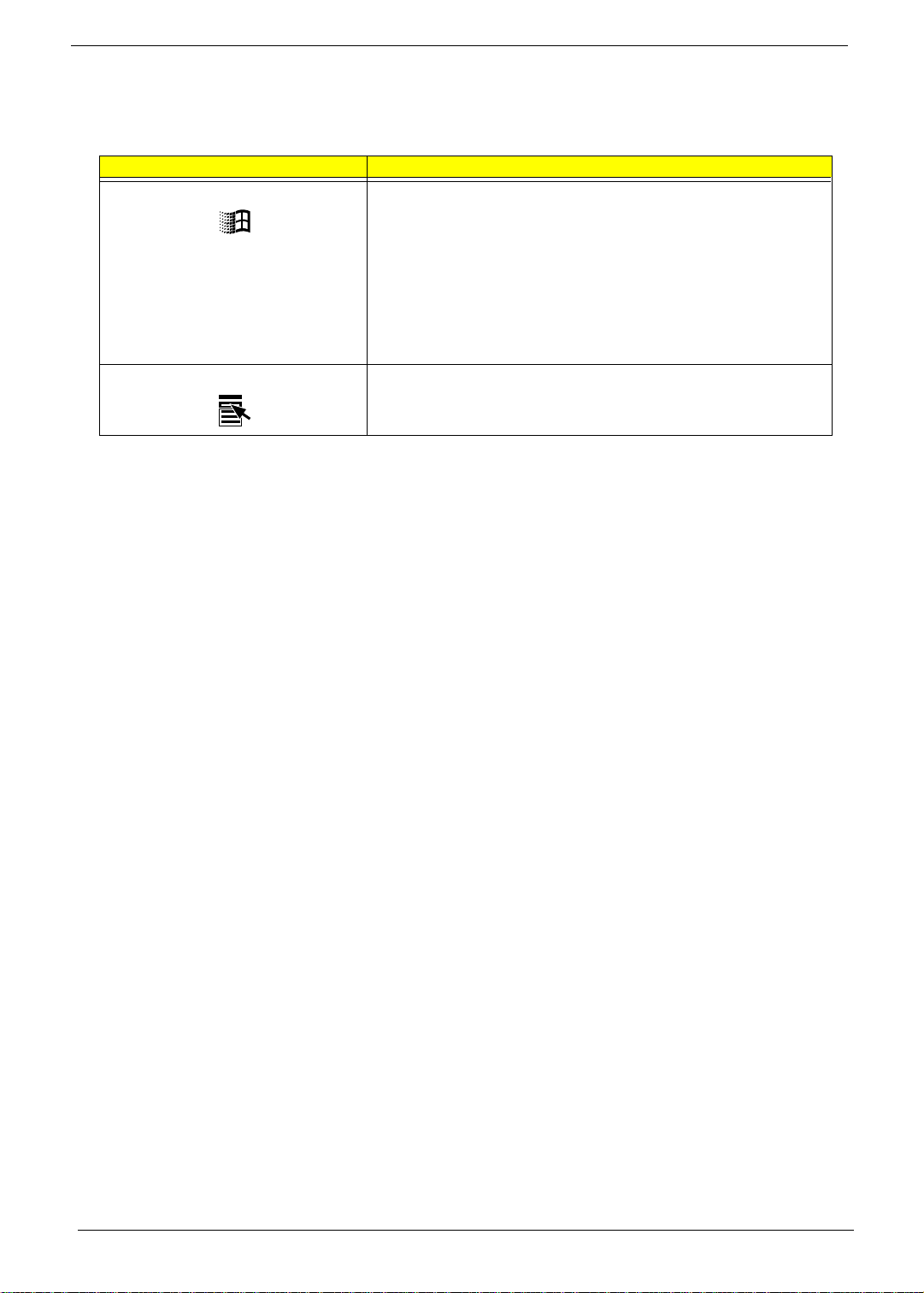
Windows keys
The keyboard has two keys that perform Windows-specific functions.
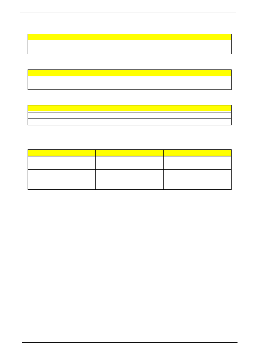
Key Description
Windows logo key Start button. Combinations with this key perform special functions, such
as:
!
Windows + Tab
!
Windows + E
!
Windows + F
!
Windows + M
!
Shift + Windows + M
!
Windows + R
Application key Opens the application’s context menu (same function as clicking the right
button of the mouse).
: Activate the next Taskbar button
: Explores My Computer
: Finds a Document
: Minimizes All
: Undoes Minimize All
: Displays the Run dialog box
10 Chapter 1
Page 19
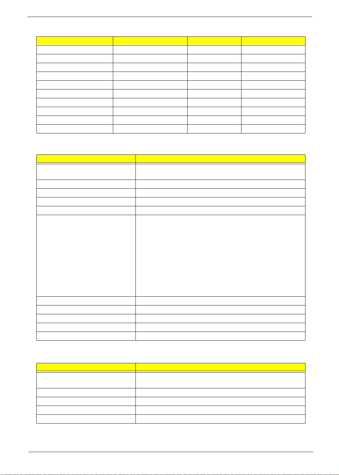
Hardware Specifications and Configurations
Processor
Item Specification
Type AcerPower Sx: Intel Pentium III, Celeron or Cyrix III processor
AcerPower Sc: Intel Tualatin Pentium III, Celeron processor
Socket 370
Speed AcerPower Sx: 500/550/600 MHz, 533/667/733 MH z
AcerPower Sc: Coppermine up to 1.1 GHz
Tualatin from 1.2 to 1.4 GHz and above
Celeron 850/950 MHz , 1.1/1.2 GHz
Minimum operating speed 0 MHz (If
Enabled
Voltage Processor voltage can be detected by the system without setting any
jumper.
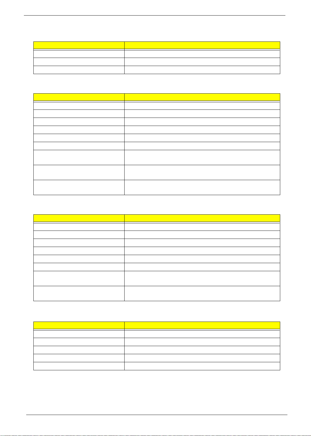
BIOS
Item Specification
BIOS code programmer Acer
BIOS version AcerPower Sx :V4.0, R01-A4
AcerPower Sc : R07-B3
BIOS ROM type Bulk mode flash ROM
BIOS ROM size AcerPower Sx: 256Kbyte
AcerPower Sc: 4MB
BIOS ROM package 32-pin DIP package
Support protocol PCI 2.2, APM1.2, DMI 2.00.1, E-IDE, ACPI 1.0, ESCD 1.03, ANSI
ATA 3.0, PnP 1a, Bootable CD-ROM 1.0, ATAPI
Boot from CD-ROM feature Yes
Support to LS-120 drive No
Support to BIOS boot block feature No
Stop CPU Clock in Sleep State in BIOS Setup
.)
is set to
NOTE:
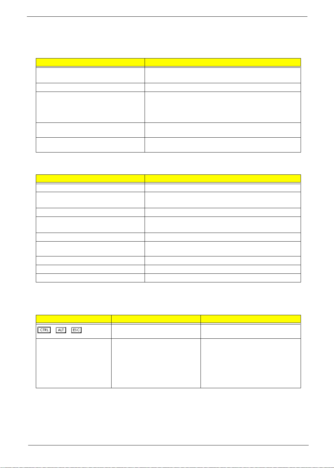
The BIOS can be overwritten/upgraded using the AFLASH utility (AFLASH.EXE).
BIOS Hotkey List
Hotkey Function Description
++
F8 Enable hidden page of BIOS Setup
Enter BIOS Setup Utility Press while the system is booting to enter
BIOS Setup Utility.
Press in BIOS Setup Utility main menu
Utility
screen, the Advanced Options menu then
appears.
The items on the Advanced Options menu
are:
Memory/Cache Options
PnP/PCI Options
Chapter 1 11
Page 20

BIOS Hotkey List
Hotkey Function Description
Alt+F4 Enable hidden page of BIOS Setup
Utility
Press in BIOS Setup Utility main menu
screen, the Advanced Options menu then
appears.
The items on the Advanced Options menu
are:
Memory/Cache Options
PnP/PCI Options
Chips Options
12 Chapter 1
Page 21
This section has two table lists, system memory specification and the possible combinations of memory
module.
System Memory
Item Specification
Memory socket number 2 sockets (2 banks)
Support memory size per socket AcerPower Sx: 32MB / 64MB / 128MB / 256MB
AcerPower Sc: 128MB / 256MB/512MB
Suppor t maximum memory size AcerPower Sx: 512MB (256MB x 2)
AcerPower Sc: 1GB (512MB x 2)
Support memory type SDRAM
Support memory speed 133MHz (PC133) (for Local Bus speed 133MHz, 100MHz
Support memory voltage 3.3 V
Support memory module package 168-pin DIMM
Support to parity check feature Yes
Support to Error Correction Code (ECC) feature Yes
Memory module combinations You can install memory modules in any combination as long as
they match the above specifications.
Memory Combinations
DIMM 1 DIMM 2 To t al
32M None 32M
64M None 64M
128M None 128M
256M None 256M
512M None 512M
None 32M 32M
None 64M 64M
None 128M 128M
None 256M 256M
None 512M 512M
32M 32M 64M
32M 64M 96M
32M 128M 160M
32M 256M 288M
64M 32M 96M
64M 64M 128M
64M 128M 192M
64M 256M 320M
128M 32M 160M
128M 64M 192M
128M 128M 256M
128M 256M 384M
256M 32M 288M
256M 64M 320M
256M 128M 384M
256M 256M 512M
Chapter 1 13
Page 22
Cache Memory
Item Specification
First-Level Cache Configurations
Cache function control Enable/Disable by BIOS Setup
Second-Level Cache Configurations
Below information is only applicable to system with installed Pentium III processor.
L2 Cache RAM type PBSRAM
L2 Cache RAM size 256-KB
L2 Cache RAM speed One-half the processor core clock frequency
L2 Cache RAM voltage Pentium III processor: 1.65V
L2 Cache function control Enable/Disable by BIOS Setup
L2 Cache scheme Fixed in write-back
Video Memory
Item Specification
Memory size 8 MB or above
Memory type SDRAM (Synchronous Dynamic RAM)
Memory configuration 1M*16 * 2
Fixed on-board or upgradeable Fixed on-board by BIOS setting
Memory speed 66/100/133 MHz
Memory voltage 3.3V
Memory package 54 pin FPGA
This section has two table lists, the video interface specification and its supported display modes.
Video Interface
Item Specification
Video controller SiS630
Video controller resident bus AGP bus
Video interface support Video YUV texture in all texture formats
H/W DVD accelerator
Display Screen Resolution Refresh Rate (Hz) Hor. Scan (KHz) Pixel Clock (MHz)
640x480 60 31.5 25.2
640x480 72 37.4 32.0
640x480 75 37.5 31.5
640x480 85 43.3 36.0
640x480 120 63.7 55.0
800x600 56 35.2 36.0
800x600 60 37.8 39.9
800x600 72 48.0 50.0
800x600 75 46.9 49.5
800x600 85 53.7 56.2
800x600 100 62.5 67.5
14 Chapter 1
Page 23
Display Screen Resolution Refresh Rate (Hz) Hor. Scan (KHz) Pixel Clock (MHz)
800x600 120 76.1 81.0
800x600 160 101.9 110.0
1024x768 70 56.5 75.0
1024x768 75 60.0 78.8
1024x768 100 79.0 110.0
1280x1024 43 50.0 80.0
1280x1024 60 64.0 110.0
1280x1024 85 91.2 157.5
1600x1200 60 76.2 156.0
1600x1200 85 106.2 229.5
Audio Interface
Item Specification
Audio controller AcerPower Sx : SiS630
AcerPower Sc : SiS630ET(Main), Crystal 4299 (CODEC)
Audio controller resident bus AC’97/98
Audio function control Enable/disable by BIOS Setup
Mono or stereo Stereo
Resolution 20 bits
Compatibility Sound Blaster Pro/16 compatible
Mixed digital and analog high performance chip
Enhanced stereo full duplex operation
High performance audio accelerator and AC’97/98 support
Full native DOS games compatibility
Virtual FM enhances audio experience through real-time FM-to-Wavetable
conversion
MPU-401(UART mode) interface for wavetable synthesizers and MIDI
devices
Integrated dual game port
Meets AC’97/98 and WHQL specifications
Music synthesizer Yes, internal FM synthesizer
Sampling rate 48 KHz (max.)
MPU-401 UART support Yes
Microphone jack Supported
Headphone jack Supported
IDE Interface
Item Specification
IDE controller AcerPower Sx :SiS630
AcerPower Sc :SiS630ET, Ultra ATA100
IDE controller resident bus PCI bus
Number of IDE channel 2
Support IDE interface E-IDE (up to PIO mode-4 and Ultra DMA 33/66), ANSIS ATA rev.3.0 ATAPI
Support bootable CD-ROM Yes
Chapter 1 15
Page 24
Floppy disk drive Interface
Item Specification
Floppy disk drive controller SiS950
Floppy disk drive controller resident bus ISA bus
Support FDD format 360KB, 720KB, 1.2MB, 1.44MB, 2.88MB
Parallel Port
Item Specification
Parallel port controller SiS950
Parallel port controller resident bus ISA bus
Number of parallel ports 1
Support ECP/EPP SPP / Bi-directional / ECP / EPP
Connector type 25-pin D-type female connector
Parallel port function control Enable/disable by BIOS Setup
Optional ECP DMA channel
(in BIOS Setup)
Optional parallel port I/O address
(via BIOS Setup)
Optional parallel port IRQ
(via BIOS Setup)
DMA channel 1
DMA channel 3
378h
278h
IRQ5
IRQ7
Serial Port
Item Specification
Serial port controller SiS950
Serial port controller resident bus ISA bus
Number of serial port 2
Serial ports location CN4, 5
16550 UART support Yes
Connector type 9-pin D-type female connector
Optional serial port I/O address
(via BIOS Setup)
Optional serial port IRQ
(via BIOS Setup)
COM1: 2F8h, 3E8h, 2E8h
COM2: 3E8h, 3F8h, 2F8h
COM1: IRQ 3, and 4
COM2: IRQ 4, and 3
Modem
Item Specification
Fax modem data baud rate (bps) V.17 12K/1.44K
Data modem data baud rate (bps) V.90 32K to 56K (received only)
Voice modem V.253
Modem connector type RJ11
Full duplex Yes
NOTE: AcerPower Sc support V.90 56K with Universal DAA Fax/Modem.
16 Chapter 1
Page 25
USB Port
Item Specification
Universal HCI USB 1.1
USB Class Support legacy keyboard for legacy mode
Memory Address Map
Address Size Function
000000 - 07FFFF 512KBytes Host Memory
080000 - 09FFFF 128KBytes Host/PCI Memory
0A0000 - 0BFFFF 128KBytes PCI/ISA Video Buffer Memory
0C0000 - 0C7FFF 32KBytes Video BIOS Memory
0C8000 - 0DFFFF 96Kbytes ISA Card BIOS & Buffer Memory
0E0000 - 0EFFFF 64Kbytes BIOS Extension Memory
Setup and Post Memory
PCI Development BIOS
0F0000 - 0FFFFF 64Kbytes System BIOS Memory
100000 - UPPER LIMIT Main Memory
UPPER LIMIT - 4GBytes PCI Memory
PCI INTx# and IDSEL Assignment Map
PCI INTx # PCI Devices Device IDSEL: ADxx
INTA# ADIMM-slot N
INTB# PCI-Slot1 AD20
INTC# PCI-Slot2 AD22
INTD# PCI-Slot3 AD24
PCI Slot IRQ Routing Map
PCI INTX# INTA INTB INTC INTD Bus Mastering
PCI slot 1 Route 4 Route 1 Route 2 Route 3 Enabled
PCI slot 2 Route 3 Route 4 Route 1 Route 2 Enabled
PCI slot 3 Route 2 Route 3 Route 4 Route 1 Enabled
Chapter 1 17
Page 26
I/O Address Map
Hex Range Devices
000-01F
020-021
040-043
060-060
061-061
070-071
080-08F
0A0-0A1
0C0-0DF
0F0-0FF
170-177
1F0-1F7
278-27F
2F8-2FF
378-37F
3F0-3F5
3F6-3F6
3F7-3F7
3F8-3FF
0CF8
0CFC
778-77A
DMA Controller-1
Interrupt Controller-1
System Timer
Keyboard Controller 8742
System Speaker
CMOS RAM Address and Real Time Clock
DMA Page Register
Interrupt Controller-2
DMA Controller-2
Math Co-Processor
Secondary IDE
Primary IDE
Parallel Printer Port 2
Serial Asynchronous Port 2
Parallel Printer Port 1
Floppy Disk Controller
Secondary IDE
Primary IDE
Serial Asynchronous Port 1
Configuration Address Register
Configuration Data Register
Parallel Printer Port 1
IRQ Assignment Map
IRQx System Devices Add-On-Card Devices
IRQ0 Timer N
IRQ1 Keyboard N
IRQ2 Cascade Interrupt Control N
IRQ3 Serial Alternate Reserved
IRQ4 Serial Primary Reserved
IRQ5 MPU-401(Alternate) Reserved
IRQ6 Floppy Disk Reserved
IRQ7 Parallel Port Reserved
IRQ8 Real Time Clock N
IRQ9 N Reserved
IRQ10 N Reserved
IRQ11 N Reserved
IRQ12 PS/2 Mouse Reserved
IRQ13 Math Coprocessor Exception N
IRQ14 Primary IDE Reserved
IRQ15 Secondary IDE Reserved
NOTE: N - Not be used
18 Chapter 1
Page 27
DRQ Assignment Map
DRQx System Devices Add-On-Card Devices
DRQ0 N Reserved
DRQ1 N Reserved
DRQ2 FDD N
DRQ3 N Reserved
DRQ4 Cascade N
DRQ5 N Reserved
DRQ6 N Reserved
DRQ7 N Reserved
NOTE: N - Not be used
Main Board Major Chips
Item Controller
System core logic SiS630 / SiS950
Video controller SiS630
Super I/O controller SiS950
Audio controller SiS630
LAN controller SiS630
HDD controller Built in SiS630
Keyboard controller Built in SiS630
RTC Built in SiS630
Environmental Requirements
Item Specifications
Temperature
Operating +10 ~ +35°C
Non-operating -20 ~ +60°C (Storage package)
Humidity
Operating 20% to 80% RH
Non-operating 20% to 80% RH
Vibration
Operating (unpacked) 5 ~ 16 Hz: 0.015 mm
16 ~ 250 Hz: 0.21 G
Non-operating (packed) 5 ~ 27.1 Hz: 0.6 G
27.1 ~ 50 Hz: 0.016 mm
50 ~ 500 Hz: 2 G
Mechanical Specifications
Item Specification
Weight
One 3 ½ FDD and one 3.5 HDD
(without packing)
Dimensions
(main footprint)
Varied by local configuration
190mm * 320mm * 360mm
Chapter 1 19
Page 28
Switching Power Supply 102W
Input Frequency Frequency Variation Range
50MHz 47MHz to 53MHz
60MHz 57MHz to 63MHz
Input Voltage Variation Range
100 - 120 VRMS 90 - 132 VRMS
200 - 240 VRMS 180 - 264 VRMS
Input Current Measuring Range
4A 90 -132 VRMS
2A 180 - 264 VRMS
NOTE: Measure at line input 90 VRMS and maximum load condition.
Output Requirements Regulation Current Rating
+5V +-5% 15A
+12V +-5% 3A
-12V +-10% 0.3A
+3.3V +-4% 12A
+5Vaux +-5% 3A
NOTE: AcerPower Sc is using 145W power supply.
20 Chapter 1
Page 29

Power Management Function (ACPI support function)
Device Standby Mode
Independent power management timer for hard disk drive devices
!
(0-15 minutes, time step=1 minute).
Hard disk drive goes into Standby mode (for ATA standard interface).
!
Disable V-sync to control the VESA DPMS monitor.
!
Resume method: device activated (Keyboard for DOS, keyboard & mouse for Windows).
!
Resume recovery time: 3-5 sec.
!
Global Standby Mode
Global power management timer (2-120 minutes, time step=10 minute).
!
Hard disk drive goes into Standby mode (for ATA standard interface).
!
Disable H-sync and V-sync signals to control the VESA DPMS monitor.
!
Resume method: Return to original state by pushing external switch button, modem ring in,
!
keyboard and mouse for APM mode.
Resume recovery time: 7-10 sec.
!
NOTE:
Suspend Mode
NOTE:
AcerPower Sc : Resume method: Return to original state by pushing external switch button, keyboard
and mouse for ACPI mode
Independent power management timer (2-120 minutes, time step=10 minutes) or pushing external
!
switch button.
CPU goes into SMM.
!
CPU asserts STPCLK# and goes into the Stop Grant State.
!
LED on the panel turns amber colour.
!
Hard disk drive goes into SLEEP mode (for ATA standard interface).
!
Disable H-sync and V-sync signals to control the VESA DPMS monitor.
!
Ultra I/O and VGA chip go into power saving mode.
!
Resume method: Return to original state by pushing external switch button, modem ring in,
!
keyboard and mouse for APM mode.
Return to original state by pushing external switch button, modem ring in and USB keyboard for
!
ACPI mode.
AcerPower Sc : Resume method: Return to original state by pushing external switch button, keyboard
and mouse for ACPI mode
ACPI
ACPI specification 1.0.
!
S0, S1, S3 and S5 sleep state support.
!
On board device power management support.
!
On board device configuration support.
!
NOTE:
Chapter 1 21
AcerPower Sc : ACPI specification 1.0b.
Page 30

22 Chapter 1
Page 31

Chapter 2
System Utilities
Most systems are already configured by the manufacturer or the dealer. There is no need to run
Setup when starting the computer unless you get a Run Setup message.
The Setup program loads configuration values into the battery-backed nonvolatile memory called CMOS RAM.
This memory area is not part of the system RAM.
NOTE: If you repeatedly receive Run Setup messages, the battery may be bad. In this case, the system
cannot retain configuration values in CMOS.
Before you run Setup, make sure that you have saved all open files. The system reboots immediately after
you exit Setup.
Chapter 2 23
Page 32

Entering Setup
Setup Utility
!
System Information
!
Product Information
!
Disk Drives
!
Onboard Peripherals
!
Power Management
!
Boot Options
!
Date and Time
!
System Security
Load Default Settings
Abort Settings Change
Setup Utility
!
System Information
!
Product Information
!
Disk Drives
!
Onboard Peripherals
!
Power Management
!
Boot Options
!
Date and Time
!
System Security
!!!!
*Advanced Options
Load Default Settings
Abort Settings Change
To enter Setup, press the key combination .
NOTE:
The Setup Utility main menu then appears:
The system supports two BIOS Utility levels: Basic and Advanced. The above screen is the BIOS Utility Basic
Level screen. It allows you to view and change only the basic configuration of your system.
If you are an advanced user, you may want to check the detailed configuration of your system. Detailed
system configurations are contained in the Advanced Level. To view the Advanced Level menu, press F8 or
the
NOTE:
You must press
Alt + F4
keys simultaneously.
The F8 and
the advanced level and hidden information only when you are in the main menu.
Alt + F4
keys work only when you are in the main menu. This means that you can activate
simultaneously while the system is booting.
The following screen shows the Advanced Level main menu:
24 Chapter 2
Page 33

The command line at the bottom of the menu tells you how to move within a screen and from one screen to
another.
To select an option, move the highlight bar by pressing or then press .
!
Press to move to the next page or to return to the previous page.
!
To change a parameter setting, press or until the desired setting is found.
!
Press to return to the main menu. If you are already in the main menu, press again to
!
exit Setup.
The parameters on the screens show default values. These values may not be the same as those in your
system.
The grayed items on the screens have fixed settings and are not user-configurable.
Chapter 2 25
Page 34

System Information
The following screen appears if you select System Information from the main menu.
System Information
Processor ................................................................Pentium III
Processor Speed ......................................................500E MHz
Level 1 Cache ......................................................... 32 KB, Enabled
Level 2 Cache..........................................................256 KB, Enabled
Diskette Drive A .....................................................1.44 MB 3.5-inch
Diskette Drive B .....................................................None
IDE Primary Channel Master .................................Hard Disk, 4311 M.B.
IDE Primary Channel Slave ...................................None
IDE Secondary Channel Master .............................None
IDE Secondary Channel Slave ...............................IDE CD-ROM
Total Memory..........................................................56 MB + 8192 KB Share Memory
1st Bank ................................................................SDRAM, 32 MB
2nd Bank ..............................................................SDRAM, 32 MB
Serial Port 1 ............................................................. Disabled
Serial Port 2 ............................................................. 3F8h, IRQ 4
Parallel Port ............................................................378h, IRQ 7
PS/2 Mouse ............................................................ Installed
This page shows the current basic configuration of your system.
The following table describes the parameters found in the System Information pages:
Parameter Description Format
Processor Specifies the type of processor currently installed in
your system.
Processor Speed Specifies the speed of the processor currently installed
in your system.
Level 1 Cache Specifies the first-level or the internal memory (i.e., the
memory integrated into the processor) size, and
whether it is enabled or disabled.
Level 2 Cache Specifies the second-level cache memory size currently
supported by the system.
Diskette Drive A Shows the diskette drive A type. Capacity, dimension
Diskette Drive B Shows the diskette drive B type. Capacity, dimension
IDE Primary Channel Master Specifies the current configuration of the IDE device
IDE Primary Channel Slave Specifies the current configuration of the IDE device
IDE Secondary Channel
Master
IDE Secondary Channel
Slave
connected to the master port of the primary IDE
channel.
connected to the slave port of the primary IDE channel.
Specifies the current configuration of the IDE device
connected to the master port of the secondary IDE
channel.
Specifies the current configuration of the IDE device
connected to the slave port of the secondary IDE
channel.
Speed in MHz
Cache size in KB
Cache size in KB
Drive type, capacity
Drive type, capacity
Drive type, capacity
Drive type, capacity
26 Chapter 2
Page 35

Parameter Description Format
Total Memory Specifies the total amount of onboard memory. The
memory size is automatically detected by BIOS during
the POST. If you install additional memory, the system
automatically adjusts this parameter to display the new
memory size.
1st Bank Indicates the type of DRAM installed in the DIMM 1
socket. The None setting indicates that there is no
DRAM installed.
2nd Bank Indicates the type of DRAM installed in the DIMM 2
socket. The None setting indicates that there is no
DRAM installed.
Serial Port 1 Shows the serial port 1 address and IRQ settings. Address, IRQ
Serial Port 2 Shows the serial port 2 address and IRQ settings. Address, IRQ
Parallel Port Shows the parallel port address and IRQ settings. Address, IRQ
PS/2 Mouse Indicates if there is a mouse connected to your system.
This is automatically detected by BIOS.
Memory size in MB
DIMM type, capacity in MB
DIMM type, capacity in MB
Displays Installed if there is a
mouse detected; otherwise, it
displays None.
Chapter 2 27
Page 36

Product Information
The screen below appears if you select Product Information from the main menu:
Product Information
Product Name ........................................................ AcerPower Sx
System S/N ............................................................ N/A
Main Board ID ....................................................... S57M
Main Board S/N ..................................................... N/A
System BIOS Version ............................................ V4.0
SMBIOS Version ...................................................2.3
System BIOS ID.....................................................R01-A4 EN-JA
BIOS Release Date .................................................Jan 06, '00
Product I nformation
Product N ame ................ ......... AcerPower Sxb
System S/ N.................... ........ N/A
Main Boar d ID................ ......... S57M
Main Boar d S/N................ ........ N/A
System BI OS Version......... .......... V4.0
SMBIOS Ve rsion................ ........ 2.3
*System B IOS ID................ ....... R06-A1
BIOS Release Dat e...... .............. . April 16,01
NOTE:
The Product Information menu contains general data about the system, such as the product name, serial
number, BIOS version, etc. These information is necessary for troubleshooting (maybe required when asking
for technical support).
This screen can be seen on Acer Power Sxb model.
28 Chapter 2
Page 37

The following table describes the parameters found in this menu:
Parameter Description
Product Name Displays the model name of your system.
System S/N Displays your system’s serial number.
Main Board ID Displays the main board’s identification number.
Main Board S/N Displays your main board’s serial number.
System BIOS Version Specifies the version of your BIOS utility.
SMBIOS version The System Management Interface (SM) BIOS allows you to check your system
hardware components without actually opening your system. Hardware checking
is done via software during start up. This parameter specifies the version of the
SMBIOS utility installed in your system.
System BIOS ID Specifies the version ID of the BIOS utility.
BIOS Release Date Displays the release date of the BIOS utility.
Chapter 2 29
Page 38

Disk Drives
Select Disk Drives from the main menu to configure the drives installed in your system.
The following screen shows the Disk Drives menu:
Disk Drives
Diskette Drive A ....................................................[1.44MB 3.5-inch]
Diskette Drive B ....................................................[None]
!
IDE Primary Channel Master
!
IDE Primary Channel Slave
!
IDE Secondary Channel Master
!
IDE Secondary Channel Slave
The following table describes the parameters found in this menu. Settings in
suggested settings.
Parameter Description Op tions
Diskette Drive A / B Allows you to configure your floppy drive None
IDE Primary Channel Master Allows you to configure the hard disk drive
connected to the master port of IDE channel 1.
IDE Primary Channel Slave Lets you configure the hard disk drive connected
to the slave port of IDE channel 1.
IDE Secondary Channel Master Allows you to configure the hard disk drive
connected to the master port of IDE channel 2.
IDE Secondary Channel Slave Lets you configure the hard disk drive connected
to the slave port of IDE channel 2.
boldface
360 KB, 5.25-inch
1.2 MB, 5.25-inch
720 KB, 3.5-inch
1.44 MB, 3.5-inch
2.88 MB, 3.5-inch
are the default and
30 Chapter 2
Page 39

IDE Primary/Secondary Channel Master/Slave
The following screen appears if you select any of the IDE drive parameters:
IDE Primary Channel Master
Device Detection Mode ..........................................[Auto]
Device Type.......................................................... Hard Disk
Cylinder................................................................[8354]
Head......................................................................[ 16]
Sector....................................................................[ 63]
Size ....................................................................... [4311] M.B.
Hard Disk LBA Mode ..........................................[Auto]
*Hard Disk Block Mode....................................... [Auto]
*Hard Disk 32 Bit Access ..................................... [Enabled ]
*Advanced PIO Mode ..........................................[Auto]
*DMA Transfer Mode..........................................[Auto]
NOTE:
The following table describes the parameters found in this menu. Settings in
*These items can only be seen when you are in the Advanced Level.
boldface
are the default and
suggested settings.
Parameter Description Options
Device Detection Mode Lets you specify the type of hard disk installed in your
system. If you want BIOS to automatically configure
your hard disk, select
disk type, you can enter the setting manually.
Setting this parameter also sets the Cylinder, Head,
Sector, and Size parameters.
Device Type Display the type of device installed. Not configurable. The default is
Cylinder Specifies your hard disk’s number of cylinders, and is
automatically set depending on your Type parameter
setting.
Head Specifies your hard disk’s number of heads, and is
automatically set depending on your Type parameter
setting.
Sector Specifies your hard disk’s number of sectors, and is
automatically set depending on your Type parameter
setting.
Size Specifies the size of your hard disk, in MB, and is
automatically set depending on your Type parameter
setting
Hard Disk LBA Mode Set to “Auto” under DOS and Windows. Set to
“Disabled” under Novell Netware and Unix.
Auto. If you know your hard
None, or User.
Auto,
The User setting allows you to enter
your settings manually if you know
your hard disk type. The Auto setting
also sets the Cylinder, Head, Sector,
and Size parameters.
Hard Disk
Only Device Detection Mode is set to
User, the item Cylinder will be
available; Otherwise it is nonconfigurable.
Only Device Detection Mode is set to
User, the item Head will be available;
Otherwise it is non-configurable.
Only Device Detection Mode is set to
User, the item Sector will be
available; Otherwise it is nonconfigurable.
It will turn to gray and will be nonconfigurable.
Auto
.
or Disabled
Chapter 2 31
Page 40

Parameter Description Options
Hard Disk Block Mode This function enhances disk performance depending
on the hard disk in use. If you set this parameter to
Auto, the BIOS utility automatically detects if the
installed hard disk drive supports the Block Mode
function. If supported, it allows data transfer in blocks
(multiple sectors) at a rate of 256 bytes per cycle.
Hard Disk 32-bit Access Enabling this parameter improves system
performance by allowing the use of the 32-bit hard
disk access. This enhanced IDE feature works only
under DOS, Windows 3.x, Windows 95/98, Windows
NT, and Novell NetWare.
Advanced PIO Mode When set to Auto, the BIOS utility automatically
detects if the installed hard disk supports the function,
it allows for faster data recovery and read/ write
timing that reduces hard disk activity time. This
results in better hard disk performance.
DMA Transfer Mode The Ultra DMA and Multi-DMA modes enhance hard
disk performance by increasing the transfer rate.
However, besides enabling these features in the
BIOS Setup, both the Ultra DMA and Multi-DMA
modes require the DMA driver to be loaded.
or Disabled
Auto
Enabled
, Mode 0, 1, 2, 3 or 4
Auto
Auto
Multiword Mode 0, 1, 2
Ultra Mode 0, 1, 2, 3, 4
Disabled
or Disabled
32 Chapter 2
Page 41

Onboard Peripherals
The Onboard Peripherals menu allows you to configure the onboard devices. Selecting this option from the
main menu displays the following screen:
Onboard Peripherals
Serial Port 1 ............................................................ [Disabled]
Base Address ........................................................ [----]
IRQ ....................................................................... [-]
Serial Port 2 ............................................................ [Enabled ]
Base Address ........................................................ [3F8h]
IRQ ....................................................................... [4]
Parallel Port ............................................................ [Enabled ]
Base Address ........................................................ [378h]
IRQ ....................................................................... [7]
Operation Mode .................................................... [EPP]
ECP DM A Channel ............................................ [-]
Floppy Disk Controller ........................................... [Enabled ]
IDE Controller ........................................................ [ Both ]
PS/2 Mouse Controller ........................................... [Enabled ]
USB Host Controller ............................................... [Enabled ]
USB Legacy Mode ............................................... [Disabled]
Onboard Audio Chip............................................... [Enabled ]
Game Port Address ................................................. [201]
MIDI Port Address ................................................. [330]
MIDI Port IRQ........................................................ [5]
Onboard Modem Chip ............................................ [Disabled]
Onboard Ethernet Chip ........................................... [Enabled ]
Chapter 2 33
Page 42

Onboard Peripherals
Serial Port 1.................... [Disabled]
Base Address .................. [----]
IRQ ........................... [-]
Serial Port 2.................... [Enabled]
Base Address .................. [3F8h]
IRQ ........................... [4]
Parallel Port ......... ........... [Enabled]
Base Address .................. [378h]
IRQ ........................... [7]
Operation Mode ................ [EPP]
ECP DMA Channel............. [-]
Floppy Disk Controller........... [Enabled]
IDE Controller................... [Both]
PS/2 Mouse Controller............ [Enabled]
USB Host Controller .............. [Enabled]
USB Legacy Mode................ [Enabled]
Onboard Audio Chip ............... [Enabled]
Game Port Address ................ [201]
MIDI Port Address ................ [330]
MIDI Port IRQ.................... [5]
Onboard Modem Chip ............... [Disabled]
Onboard Ethernet Chip............ [Enabled]
NOTE: This screen can be seen on Acer Power Sxb model.
The following table describes the parameters found in this menu. Settings in boldface are the default and
suggested settings.
Parameter Description Options
Serial Port 1 Lets you enable or disable the serial port 1. Enabled or
Base A ddress Lets you set a logical base address for each
serial port. This parameter is configurable only
if the Serial Port parameter is enabled.
IRQ Lets you assign an interrupt for each serial port.
This parameter is configurable only if the Serial
Port parameter is enabled.
Serial Port 2 Lets you enable or disable the serial port 2.
Base Address Lets you set a logical base address for each
serial port. This parameter is configurable only
if the Serial Port parameter is enabled.
IRQ Lets you assign an interrupt for each serial port.
This parameter is configurable only if the Serial
Port parameter is enabled.
Parallel Port Lets you enable or disable the parallel port.
Base Address Lets you set a logical base address for the
parallel port. This parameter is configurable
only if the Parallel Port parameter is enabled.
IRQ Lets you assign an interrupt for the parallel port.
This parameter is configurable only if the
Parallel Port parameter is enabled.
Enabled
3F8h
or 11
4
Enabled
378h
5 or
Disabled
or Disabled
, 3E8h, 2E8h
or Disabled
, 278h
7
34 Chapter 2
Page 43

Parameter Description Options
Operation Mode Lets you set your parallel port’s operation
mode. This parameter is configurable only if the
Parallel Port parameter is enabled.
ECP DMA Channel Allows you to assign a DMA channel for the
ECP parallel port function. This parameter is
configurable only if you select the Extended
Capabilities Port (ECP) as the operation mode.
Floppy Disk Controller Lets you enable or disable the onboard floppy
disk controller.
IDE Controller Lets you enable or disable the onboard primary,
secondary or both IDE interfaces.
PS/2 Mouse Controller Lets you enable or disable the onboard PS/2
mouse controller
USB Host Controller Lets you enable or disable the onboard USB
host controller.
USB Legacy Mode Lets you activate or deactivate the USB
keyboard connected to your system. When
activated, the USB keyboard functions in a DOS
environment.
Onboard Audio Chip Lets you enable or disable the onboard audio
controller
Game Port Address Lets you set the I/O base address of the game
port.
MIDI Port Address Lets you set the I/O base address of the midi
port.
MIDI Port IRQ Lets you set the IRQ channel of the midi port.
Onboard Modem Chip Lets you enable or disable the onboard modem
controller.
Onboard Ethernet Chip Lets you enable or disable the onboard ethernet
(LAN) controller.
Standard Parallel Port (SPP)
Bidirectional
Enhanced Parallel Port (EPP)
Extended Capabilities Port (ECP)
, 3
1
Enabled
Primary,
Enabled
Enabled
Enabled or
Enabled
201
330
5
Enabled or
Enabled
or Disabled
Both
or Disabled
or Disabled
or Disabled
, 209, Disabled
, 300, Disabled
, 7
or Disabled
, or Disabled
Disabled
Disabled
Chapter 2 35
Page 44

Power Management
The Power Management menu lets you configure the system power-management feature. It works only under
APM mode.
IMPORTANT:
If an ACPI-aware operating system such as Windows 98 or Windows 2000 is installed in ACPI
mode, the operating system will use the ACPI interfaces. Then the settings in Power Management
page is non-effective.
The following screen shows the Power Management parameters and their default settings:
Power Management
Power Management Mode .....................................[Enabled ]
IDE Hard Disk Standby Timer ............................[OFF]
System Sleep Timer .............................................[30] Minute(s)
Sleep Mode ........................................................[Suspend]
Power Switch < 4 sec.............................................. [Power Off]
System wake-up event
Modem Ring Indicator.......................................... [Enabled ]
PCI Power Management .......................................[Enabled ]
Restart on AC/Power Failure ................................. [Enabled ]
The following table describes the parameters found in this menu. Settings in
suggested settings.
Parameter Description Options
Power Management Mode Allows you to reduce the system’s power
consumption. When enabled, the IDE hard
disk and system timers become
configurable.
IDE Har d Disk Standby Timer Allows the hard disk to enter Standby mode
after inactivity of 1 to 15 minutes, depending
on your setting.
System Sleep Timer Automatically puts the system to power-
saving mode after a specified period of
inactivity. Any keyboard or mouse action, or
any activity detected from the IRQ channels
resumes system operation.
Sleep Mode Lets you specify the power-saving mode
that the system will enter after a specified
period of inactivity. This parameter is
configurable only if the System Sleep Timer
is enabled.
Power Switch < 4 sec. Lets you specify whether to automatically
turn off the machine or put the system to
Suspend mode when the power switch is
pressed for less than 4 seconds.
System Wake-up Event Lets you specify the activity that will resume
the system to normal operation.
boldface
Enabled
1 to 15 minutes, or
2, 5, 10, 15, 20, 30, 40,
50...120 minutes, or Off
Standby or
Power Off
are the default and
or Disabled
Suspen d
or Suspend
Off
36 Chapter 2
Page 45

Parameter Description Options
Modem Ring Indicator Wakes the system from Sleep mode once
any fax/modem activity is detected.
PCI Power Management Allows the system to be awaken by the PME
function.
Restart on AC/ Power Failure
Enabled
Enabled
Enabled
or Disabled
or Disabled
or Disabled
Chapter 2 37
Page 46

Boot Options
This option allows you to specify your preferred settings for bootup.
The following screen appears if you select Boot Options from the main menu:
Boot Options
Boot Sequence
1st. [Floppy Disk A:]
2nd.[Hard Disk C:]
3rd.[IDE CD-ROM]
Fast Boot................................................................. [ Auto ]
Silent Boot.............................................................. [Enabled ]
Num Lock After Boot............................................. [Enabled ]
Memory Test........................................................... [Disabled]
*Configuration Table ........................................... [Enabled ]
Language Type ....................................................... [English]
!
!
!
NOTE:
*This item can only be seen when you are in the Advanced Level.
The following table describes the parameters found in this menu. Settings in
suggested settings.
Parameter Description Options
Boot Sequence Allows you to specify the boot search sequence.
Fast Boot Allows you to define your system’s booting
process, whether to skip some POST routines
or proceed with the normal booting process.
Silent Boot When enabled, BIOS is in graphical mode and
Num Lock After Boot Allows you to activate or deactivate the Num
Memory Test Lets you specify whether you want BIOS to
Configuration Table Display preboot system configuration table.
Language Type Select a language type as a based language for
displays only an identification logo during POST
and while booting. Then, the screen displays the
operating system prompt (as in DOS) or logo (as
in Windows). If any error occurs while booting,
the system automatically switches to the text
mode.
You may also switch to the text mode while
booting by pressing F9 after you hear a beep
that indicates the activation of the keyboard.
Lock function upon booting.
perform or bypass the RAM test during POST.
showing messages. Press F5 to switch
language version.
boldface
Floppy Disk
Hard Disk
IDE CD-ROM
Auto
or Disabled
Enabled
Enabled
Enabled or
Enabled
English
or Disabled
or Disabled
or Disabled
or Japanese
are the default and
Disabled
38 Chapter 2
Page 47

Date and Time
The following screen appears if you select the Date and Time option from the main menu:
Date and Time
Date ........................................................................[Mon Jan 03, 2000]
Time ....................................................................... [HH:MM:SS]
The following table describes the parameters found in this menu:
Parameter Description Options
Date Lets you set the date following the weekday-
month-day-year format.
Time Lets you set the time following the hour-minute-
second format.
Weekday: Sun, Mon, Tue, Wed, Thu, Fri,
Sat
Month: Jan, Feb...Dec
Day: 1 to 31
Year: 1980 to 2099
Hour: 0 to 23
Minute: 0 to 59
Second: 0 to 59
Chapter 2 39
Page 48

System Security
The Setup program has a number of security features to prevent unauthorized access to the system and its
data.
The following screen appears if you select System Security from the main menu:
System Security
Supervisor Password............................................... [None]
User Password ....................................................... [-----]
Disk Drive Controller
Floppy Drive ........................................................ [Normal]
Hard Disk Drive ................................................... [Normal]
Processor Serial Number ........................................ [Disabled]
The following table describes the parameters found in this menu. Settings in
suggested settings.
Parameter Description Options
Supervisor Password Prevents unauthorized access to the BIOS
utility.
User Password Secures your system against unauthorized
use. Once you set this password, you have
to type it whenever you boot the system.
Disk Drive Controller Allows you to protect your system’s floppy
drive and hard disk data from being modified
(possible under DOS mode only).
Floppy Drive Protects your floppy drive data from being
modified.
Hard Disk Drive Protects your hard disk data from being
modified.
Processor Serial Number Enables or Disables the processor serial
number (only if system have PIII processor).
None
or Present. The Present setting
allows you to set a Setup password. For
instructions on how to set a Setup
password, refer to “Setting a Password”
on page 41.
Normal
Protect Boot Sectors
Normal
Protect Boot Sectors
Enabled or
boldface
, Write Protect All Sectors, Write
, Write Protect All Sectors, Write
are the default and
Disabled
40 Chapter 2
Page 49

Setting a Password
1.
Enter the BIOS utility and select “System Security” .
2.
Highlight the “Supervisor Password” parameter and press Enter. The following screen appears:
Enter your Password twice. The Password
may be up to 7 characters long.
Supervisor Password
Enter Password .....................................................[
Enter Password again............................................[
"""""""
"""""""
]
]
Set or Change Password
NOTE:
3.
NOTE:
4.
5.
6.
7.
8.
9.
10.
If you have set a Supervisor password, the next time you want to enter the BIOS utility, you must key-in your
Supervisor password.
If you have set a User password, you must enter that password every time you boot your system.
You can enable the “User Password” only if the “Supervisor Password” has been set.
Type a password. The password may consist of up to seven characters. Then press
Be very careful when typing your password because the actual characters do not appear on the
screen.
Retype the password then press
After setting the password, highlight the “Set or Change Password” option.
Esc
Press
Press
Press
Select “
After rebooting, turn off the system then open the housing.
to return to the System Security screen.
Esc
to return to the Main menu.
Esc
to exit the BIOS utility. A dialog box appears asking if you want to save the CMOS data.
Yes
” to save the changes and reboot the system.
Enter
.
Enter
.
Chapter 2 41
Page 50

Changing or Removing the Password
If you want to
1.
Enter the BIOS utility and select “System Security”.
2.
Highlight the “Supervisor Password” parameter (for Supervisor password) or the “User Password”
parameter (a Supervisor Password must be set first before you can change the User password). The
Password menu appears.
3.
From the Password menu, highlight the “Set or Change Password” option.
4.
Enter a new password.
5.
Press
6.
Press
7.
Press
8.
Select “
To remove the password
the “User Password” parameter (a Supervisor Password must be set first before you can change the User
password) from the System Security menu and set it to “None”.
change one of your passwords
Esc
to return to the System Security screen.
Esc
to return to the main menu.
Esc
to exit the BIOS utility. A dialog box appears asking if you want to save the CMOS data.
Yes
” to save the changes.
, simply select the “Supervisor Password” parameter (for Supervisor password) or
, do the following:
Bypassing the Password
If you forgot your password, you can bypass the password security feature thru hardware configuration.
Follow these steps to bypass the password:
1.
Turn off and unplug the system.
2.
Open the system housing and set
3.
Turn on the system and enter the BIOS utility. This time, the system does not require you to type-in a
password.
You can either change the existing password or remove it by selecting None. Refer to “Changing or Removing
the Password” on page 42 for the procedure.
JP11
2-3
to
to bypass the password function.
42 Chapter 2
Page 51

Advanced Options
NOTE:
The “Advanced Options” menu allows you to configure the system memory and PCI device settings.
The following screen shows the Advanced Options parameters:
The Advanced Options menu is only available if you press F8 or
Advanced Options
! Memory/Cache Options
! PnP/PCI Options
Alt + F4
in the main menu.
CAUTION:
Do not change any settings in the Advanced Options menu if you are not a qualified technician to
avoid damaging the system.
Memory/Cache Options
Selecting “Memory/Cache Options” from the Advanced Options menu displays the following screen:
This menu lets you configure the system memory.
Memory /Cache Options
Level 1 Cache......................................................... [Enabled ]
Level 2 Cache......................................................... [Enabled ]
Memory at 15MB-16MB Reserved for ..................[System]
Chapter 2 43
Page 52

The following table describes the parameters found in this sub-menu. Settings in boldface are the default and
suggested settings.
Parameter Description Options
Level 1 Cache (processor
Cache)
Level 2 Cache Lets you enable or disable the secondary cache
Memory at 15MB-16MB
Reserved for
Lets you enable or disable the primary cache
memory, i.e., the processor memory.
memory.
To prevent memory address conflicts between
the system and expansion boards, reserve this
memory range for the use of either the system
or an expansion board. Some VGA cards have
required settings for this feature. Check your
VGA card manual before setting this parameter.
Enabled
Enabled
System
or Disabled
or Disabled
or Add-on card
44 Chapter 2
Page 53

PnP/PCI Options
The PnP/PCI Options menu allows you to specify the settings for your PCI devices. Selecting this option
displays the following screen:
PnP/PCI Options
PCI IRQ Setting .....................................................[Auto]
PCI Slot 1 .....................................[--] [--] [--] [--]
INTA INTB INTC INTD
PCI Slot 2 .....................................[--] [--] [--] [--]
PCI Slot 3 .....................................[--] [--] [--] [--]
PCI IRQ Sharing ..................................................... [Yes]
VGA Palette Snoop.................................................[Disabled]
Graphics Aperture Size...........................................[64 ] MB
Plug and Play OS.................................................... [Yes]
Reset Resource Assignments.................................. [No ]
The following table describes the parameters found in this sub-menu. Settings in
suggested settings.
Parameter Description Options
PCI IRQ Setting Allows you to automatically or manually configure
the Plug-and-Play (PnP) devices installed in your
system. Refer to your device manual for technical
information about the PCI card.
PCI Slot 1 / 2 / 3 Allows you to manually assign an interrupt for each
PCI device installed in your system. When the PCI
IRQ Settings is set to Auto, BIOS automatically
assigns the available IRQs to the PCI devices.
PCI IRQ Sharing Allows you to assign the same IRQ to two different
devices.
VGA Palette Snoop Enables the palette snooping feature (if you installed
more than one VGA card in the system) allowing
the control palette register (CPR) to manage and
update the VGA RAM DA C (Digital Analog
Converter, a color data storage) of each VGA card
installed in the system. The snooping process lets
the CPR send a signal to all the VGA cards so that
they can update their individual RAM DACs. The
signal goes through the cards continuously until all
RAM DACs data has been updated. This allows the
display of multiple images on the screen. Some
VGA cards have required settings for this feature.
Check your VGA card manual before setting this
parameter.
Graphics Aperture Size This parameter determines the effective size of the
graphics aperture. Graphics aperture is the address
range that the AGP video and the CPU use to
manage graphical objects.
Auto
Yes
Enabled or
The lowest setting is 8 MB and the
highest is 256 MB.
boldface
or Manual
or No
are the default and
Disabled
Chapter 2 45
Page 54

Parameter Description Options
Plug and Play OS Set to
Win98 or Win2000. For any other OS, set to No.
Reset Resource
Assignments
When enabled, avoids IRQ conflict when installing
non-PnP and PnP PCI cards. This clears all
resource assignments and allows BIOS to reassign
resources to all inst alled PnP devices the next time
the system boots.
if the computer is running on Win95/
Yes
Chipset Settings
The Chipset Settings will be shown only if you press
!
Memory/Cache Options
!
PnP/PCI Options
!
*Chipset Settings
Alt + F4
Advanced Options
in main menu:
or No
Yes
Yes or
No
After clearing the resource data, it
is recommended that you reset
the parameter to its default, i.e.,
No.
Press Enter to view the Chipset settings information.
The following screen displays the Chipset settings menu:
Chipset Settings
Spread Spectrum .........................................[ Enabled ]
Memory Stable Register .............................. [ Enabled ]
RIMM TRDLY value ..................................[ Auto ]
ICH Audio Controller..................................[ Enabled ]
ICH Modem Controller ...............................[ Disabled ]
Delay Transaction ....................................... [ Enabled ]
46 Chapter 2
Page 55

Parameter Description Options
Load Default Settings
Do you want to load default settings?
[Yes] *[No]
Spread Spectrum In order to force EMI pass, this function allows
frequency to modulate in an acceptable range.
Memory Stable Register This function enables memory run in stable status.
RIMM TRDLY value This field defines the minimum round trip
propagation time of the RAMbus channel in unit of
Rambus clocks.
ICH Audio Controller Enables ICH audio chipset function
ICH Modem Controller Enables ICH modem chipset function only when
AMR adapter card is available.
Delay Transaction This function frees PCI bus occupied by the
processor request transaction.
Enabled
Enabled
0, 1, 2, 3, 4, or
Enabled
Enabled or
Enabled
or Disabled
or Disabled
or Disabled
Disabled
or Disabled
Auto
Load Default Settings
You need to reload the BIOS default settings every time you make changes to your system hardware
configuration (such as memory size, CPU type, hard disk type, etc.); otherwise, BIOS will keep the previous
CMOS settings. Selecting this option displays the following dialog box:
Choosing
Yes
enables BIOS to automatically detect the hardware changes that you have made in your
system. This option also allows you to restore the default settings.
Choosing No returns you to the main menu without loading the default settings.
Chapter 2 47
Page 56

Abort Settings Change
Abort Settings Change
Do you really want to abort settings change?
*[Yes] [No]
Selecting the Abort Settings Change option from the main menu displays the following dialog box:
Choosing
saved settings.
Choosing No returns you to the main menu. BIOS retains all changes that you have made.
Yes
discards all the changes that you have made and reverts the parameters to their previously
48 Chapter 2
Page 57

Exiting Setup
Exit Setup
Settings have been changed.
Do you want to save CMOS settings?
*[Ye s] [N o]
To exit the BIOS utility, simply press
Yes
Select
settings, you will be asked if you want to keep the changes made to the BIOS. Select
changes before you exit Setup. Select No to discard all changes and exit Setup.
to exit Setup. Select No to return to the main menu. If you have made changes in the parameter
Esc
. The following dialog box appears:
Yes
to save your
Chapter 2 49
Page 58

50 Chapter 2
Page 59

Machine Disassembly and Replacement
This chapter contains step-by-step procedures on how to disassemble the AcerPower Sx for maintenance
and troubleshooting.
To disassemble the computer, you need the following tools:
Wrist grounding strap and conductive mat for preventing electrostatic discharge
!
Flat-bladed screwdriver
!
Phillips screwdriver
!
Hexagonal screwdriver
!
Plastic stick
!
NOTE: The screws for the different components vary in size. During the disassembly process, group the
screws with the corresponding components to avoid mismatches when putting back the components.
Chapter 3
Chapter 3 51
Page 60

Removing a DIMM
1.
Press the holding clips on both sides of the socket outward to release the DIMM.
2.
Gently pull the DIMM out of the socket.
NOTE:
The system automatically detects the amount of memory installed. Run Setup to view the new value
for total system memory and make a note of it.
52 Chapter 3
Page 61

Removing the CPU Fan-sink and CPU Board
1.
Detach the fan-sink and fan from the CPU.
2.
Pull up the socket lever.
Chapter 3 53
Page 62

3. Remove the CPU.
54 Chapter 3
Page 63

Opening the Housing
IMPORTANT:
1.
Place the system unit on a flat, steady surface.
2.
Remove the four screws from the rear panel. Set the screws aside. You will need them when replacing
the housing cover.
3.
Push the housing cover slightly backward.
4.
Pull the housing cover upward and remove it from the chassis.
Turn off the system power (unplug the power cord) before opening the system or connecting or
removing any peripheral device.
Chapter 3 55
Page 64

Removing an Expansion Board
1.
Remove the screw on the bracket of an expansion board. Set the screw aside. You will need it when
replacing the expansion board.
2.
Gently pull out the board to remove it from the expansion slot.
56 Chapter 3
Page 65

Removing a 3.5-inch Drive
Follow these steps to install a 3.5-inch diskette drive or a hard disk drive:
1.
Disconnect the disk drive cables and the power cable.
Chapter 3 57
Page 66

2. Remove the 3.5-inch drive frame from the housing by pressing the tab on top and pivoting the frame
outward.
NOTE: A metal drive cover should be pulled out before you install a new drive into an empty 3.5-inch bay. This
cover should be removed if a 3.5-inch drive is installed. The function of the cover is to prevent EMI
effects.
3. Remove the screws along the sides of the drive frame and carefully pull out the 3.5-inch disk drive.
58 Chapter 3
Page 67

Removing a 5.25-inch Drive
To remove a 5.25-inch diskette drive or a CD-ROM drive:
1.
Disconnect the diskette drive cable and the power cable.
2.
Remove the screws on the sides and gently pull out the diskette drive or CD-ROM to remove it from the
housing.
Chapter 3 59
Page 68

Removing the Main board
1.
Lay the housing on its side with the open area facing upward.
2.
Remove all the necessary screws and carefully pull out the main board.
60 Chapter 3
Page 69

Removing a Daughterboard
1.
Remove the two screws from the daughterboard.
2.
Pull up the daughterboard.
Chapter 3 61
Page 70

62 Chapter 3
Page 71

Troubleshooting
This chapter provides troubleshooting information for AcerPower Sx model:
Power-On Self-Test (POST)
!
Index of Error Messages
!
Index of Error Codes and Error Beeps
!
Index of Error Symptoms
!
Undetermined Problems
!
Chapter 4
Chapter 4 63
Page 72

Power-On Self-Test (POST)
Each time you turn on the system, the Power-on Self Test (POST) is initiated. Several items are tested during
POST, but is for the most part transparent to the user.
The Power-On Self Test (POST) is a BIOS procedure that boots the system, initializes and diagnoses the
system components, and controls the operation of the power-on password option. If POST discovers errors in
system operations at power-on, it displays error messages on screen, generates a check point code at port
80h or even halts the system if the error is fatal.
The main components on the main board that must be diagnosed and/or initialized by POST to ensure system
functionality are as follows:
Microprocessor with built-in numeric co-processor and cache memory subsystem
!
Direct Memory Access (DMA) controller
!
Interrupt system
!
Three programmable timers
!
ROM subsystem
!
RAM subsystem
!
RTC RAM subsystem and real time clock/calendar with battery backup
!
Onboard serial interface controller
!
Onboard parallel interface controller
!
Embedded hard disk interface and one diskette drive interface
!
Keyboard and auxiliary device controllers
!
I/O ports
!
PS/2-compatible mouse port
!
PS/2-compatible keyboard port
!
Serial ports
!
Parallel ports
!
USB port
!
64 Chapter 4
Page 73

POST Check Points
When POST executes a task, it uses a series of preset numbers called check point to be latched at port 80h,
indicating the stages it is currently running. This latch can be read and shown on a debug board.
Table D-1 describes the Acer common tasks carried out by POST. A unique check point number represents
each task.
Table D-1 POST Check Points
Check Point Description
04H Determines if the current booting procedure is from cold boot (press reset button or turn
the system on), from warm boot (press CTRL + ALT + DEL or from exiting BIOS setup.
Check CPU ID, dispatch shutdown Path.
NOTE:
08H Disables Non-Maskable Interrupt (NMI), Alarm Interrupt Enable (AIE), Periodical Interrupt
Enable (PIE), and Update-ended Interrupt Enable (UIE).
NOTE:
09H Initializes chipset point (I)
10H DMA Controller (8327) test and initialization.
14H System timer (8254) test and initialization
18H Memory refresh test; refresh occurrence verification (IRQ0)
1CH 1. Verifies CMOS shutdown byte, battery and check sum.
NOTE:
The CMOS shutdown byte verification assures that CMOS 0Fh area is fine to execute
POST properly.
2. Initializes CMOS default setting
3. Initializes RTC time base
NOTE:
1EH 1. Search DRAM existence on each DRAM slot
2. DRAM type determination
2CH 1. Tests 384K base memory
2. Set default SS:SP = 0:400
NOTE:
30H System shadow RAM
20H 1. Tests keyboard controller (8041/8042)
2. Determines keyboard type (AT, XT, PS/2)
24H 1. Test programmable interrupt controller
2. Initializes system interrupt
26H Initializes GPIO
34H DRAM sizing
36H Initialize I/O APIC
3CH Sets interrupt service for POST
2DH Set CPU (s) multiple
3FH Enables/Disables USB Host Controller
At the beginning of POST, port 64 bit 2 (8042 system flag) is read to
determine whether this POST is caused by cold or warm boot. If it is a cold
boot, a complete POST is performed. If it is a warm boot, the chip initialization
and memory test is eliminated from he POST routine.
These interrupts are disabled in order to avoid any mis-action happened
during the POST routine.
Several parts of the POST routine require the system to be in protected
mode. When returning to real mode from protected mode, the processor is
reset, therefore POST is re-entered. In order to prevent re-initialization of the
system, POST reads the shutdown code stored in location 0Fh in CMOS
RAM. Then it jumps around the initialization procedure to the entry point.
The RTC has an embedded oscillator that generates 32.768 Hz frequency. To
initialize the RTC time base, turn on this oscillator and set a divisor to 32768
so that RTC can count time correctly.
The 384K base memory area is tested for POST execution. The remaining
memory ares is tested later.
Chapter 4 65
Page 74

Check Point Description
35H PCI pass 0
4EH Scan PnP Devices
4FH Config PnP Devices
40H Initial PCI (1)
41H Initial PCI (2)
42H Initial PCI (3)
44H Initial PCI (4)
45H Initial PCI (5)
50H Initializes video display
NOTE:
51H Copy F-seg from ROM into shadow RAM
54H Process VGA shadow region
4CH Check CPU brand, ID and external frequency
58H 1. Displays Acer (or OEM) logo (if necessary)
2. Displays Acer copyright message (if necessary).
3. Displays BIOS serial number.
59H Hook INT 1CH for Quiet Boot.
64H Tests keyboard interface
NOTE:
5CH Memory test (except the 384K base memory)
5EH Load Pentium Pro CPU update code
5AH Test SM RAM
5FH Enables/Disables USB Function
60H 1. Initializes SRAM cache capacity
2. Enables the cache function
70H Initializes parallel port(s)
74H Initializes parallel port(s)
78H Reset math coprocessor
7CH Check and initialize pointing device
80H Set security status
82H Prepare entering SETUP for user pressing CTRL + ALT DEL.
84H Keyboard device initialization
6CH 1. Tests and initializes FDD
2. The FDD LED should flash once and its head should be positioned
88H 1. Sets HDD type and features (i.e. transfer speed, mode,....)
2. Tests HDD controller
90H Displays POST status
93H Rehook INT 1CH for Quiet Boot
94H 1. Initializes I/O ROM
2. I/O ROM is an optional extension of the BIOS located on an installed add-on card as
part of the I/O subsystem. POSt detects I/O ROMs and gives them opportunity to
initialize themselves and their hardware environment.
96H Initializes PCI I/O ROM
A0H Sets time and day
A4H Initializes security features
A2H Initializes setup items
A8H Setup SMI parameters
If system has any display card, it should be initialized via its I/O ROM or
corresponding initialization program.
The keyboard LEDs should flash once
.
66 Chapter 4
Page 75

Check Point Description
ACH 1. Enables NMI
2. Checks parity, if set
3. Clear screen
B0H 1. Checks power-on password
2. Displays configuration mode table
3. Clear memory buffer used for POST
B1H Bootint
Chapter 4 67
Page 76

POST Error Messages List
If you cannot run the diagnostics program tests but did receive a POST error message, use “POST Error
Messages List” to diagnose system problems. If you did not receive any error message, look for a description
of your error symptoms in “Error Symptoms List” on page 70
NOTE:
When you have deemed it necessary to replace an FRU, and have done so, you must run a total
system check to ensure that no other activity has been affected by the change. This system check can
be done through the diagnostics program.
NOTE:
Check all power supply voltages, switch, and jumper settings before you replace the main board. Also
check the power supply voltages if you have a “system no-power” condition.
If you are unable to correct the problem by using the “BIOS Messages List” table and “Error Symptoms List”
table, go to “Undetermined Problems” on page 76.
NOTE:
To diagnose a problem, first find the BIOS error messages in the left column. If directed to a check
procedure, replace the FRU indicated in the check procedure. If no check procedure is indicated, the
first Action/FRU listed in right column is the most likely cause.
BIOS Messages Action/FRU
I/O Parity Error
CPU Clock Mismatch 1. Enter BIOS Setup and load the default settings.
Real Time Clock Error
CMOS Battery Bad
CMOS Checksum Error
Equipment Configuration Error 1. Ensure the system configuration set in BIOS Setup is
System Management Memory Bad
Memory Error at MMMM:SSSS:OOOOh
RAM Parity Error 1. Enter BIOS Setup to disable parity check.
PS/2 Keyboard Error or Keyboard Not Connected
PS/2 Keyboard Interface Error
PS/2 Keyboard Locked
Onboard xxx... Conflict(s) 1. Enter BIOS Setup and load the default settings.
Floppy Disk Controller Error
Floppy Drive A Error
Floppy Drive B Error
On Board Parallel Port Conflict(s)
On Board Serial Port 1 Conflict(s)
On Board Serial Port 2 Conflict(s)
Floppy Drive(s) Write Protected
Hard Disk Drive(s) Write Protected
1. S
2. Ensure BIOS setting for processor is set correctly.
1. Enter BIOS Setup and load the default settings.
2. RTC Battery.
3. System Board.
2. Enter BIOS Setup and load the default settings.
3. RTC battery.
4.
1. Insert the memory modules in the DIMM sockets
2. Memory module.
3. System board.
2. Memory module
3. System board
1. Re-connect PS/2 keyboard and mouse.
2. Enter BIOS Setup and load the default settings.
3. PS/2 keyboard
4. PS/2 mouse
5. System board
2. Remove all adapter cards that are NOT factory-
1. Diskette drive cable/connection.
2. Diskette drive.
3. System board
1. Enter BIOS Setup and load the default settings.
2. Remove all adapter cards that are NOT factory-
1. Ensure that the diskette drive is not set to [Write
2. Load default settings in Setup.
.
ystem boa
correct.
System board
properly, then reboot the system.
installed, then reboot the system.
installed, then reboot the system.
Protected] in the Security Options in BIOS Setup.
rd
.
68 Chapter 4
Page 77

BIOS Messages Action/FRU
IDE Drive 0 Error
IDE Drive 1 Error
IDE Drive 2 Error
IDE Drive 3 Error
IRQ Setting Error
Expansion ROM Allocation Fail
I/O Resource Conflict(s)
Memory Resource Conflict(s)
PCI Device Error 1. Load default settings in Setup.
PS/2 Pointing Device Interface Error
PS/2 Pointing Device Error
DMI Table Was Destroyed 1. Flash BIOS
Press CTRL + ALT + DEL key to enter Setup or F1
key to continue
Press ESC to turn off NMI, or any key to reboot 1. Press ESC to reject NMI error or press any other key
Insert system diskette and press ENTER key to
reboot
1. Enter BIOS Setup and load the default settings.
2. Check IDE drive jumper.
3. IDE hard disk drive power.
4. IDE hard disk drive cable/connection.
5. IDE hard disk drive.
1. Load default settings in Setup.
2. Ent er BIOS Setup and set the
Assignments
then reboot the system.
3. Remove all adapter cards that are NOT factoryinstalled, then reboot the system
2. Ent er BIOS Setup and set the
Assignments
then reboot the system.
3. Remove all adapter cards that are NOT factoryinstalled, then reboot the system.
1. Re-connect PS/2 keyboard and mouse.
2. Enter BIOS Setup and load the default settings.
3. PS/2 mouse
4. PS/2 keyboard
5. System board
1. Press CTRL + ALT + DEL to enter Setup and
reconfigure the system.
to reboot the system.
1. Insert a bootable disk into the floppy disk drive or
remove this disk if a hard disk is installed.
of the
of the
Reset Resource
PnP/PCI Options
Reset Resource
PnP/PCI Options
to Yes,
to Yes,
Chapter 4 69
Page 78

Error Symptoms List
NOTE:
To diagnose a problem, first find the error symptom in the left column. If directed to a check procedure,
replace the FRU indicated in the check procedure. If no check procedure is indicated, the first Action/
FRU listed in right column is the most likely cause
.
Error Symptom Action/FRU
Processor / Processor Fan
NOTE:
Normally, the processor fan should be operative, and the processor clock setting should be
exactly set to match its speed requirement before diagnosing any processor problems.
Processor fan does not run but power supply
fan runs.
Processor test failed. 1. Processor
NOTE:
Ensure the memory modules are installed properly and the contact leads are clean before
1. Ensure the system is not in power saving mode. See “Power
Management” in chapter 2.
2. With the system power on, measure the voltage of processor fan
connector. Its reading should be +12V dc.
3. System board.
System board
2.
System Board and Memory
diagnosing any system problems.
Memory test failed. 1. See "Memory"
Incorrect memory size shown or repeat ed
during POST.
System works but fails to enter power saving
mode when the
is set to
set in BIOS has elapsed.
System hangs before system boot. 1. See "Index of Symptoms"
System hangs after system boot. 1. Execute a system test and set it to stop at “Halt on Error” to see
Blinking cursor only; system does not work. 1. Diskette/IDE drive connection/cables
NOTE:
Power Management Mode
Enabled
, and power saving timer
Ensure the diskette drive is configured correctly in BIOS Setup and its read/write head is
2. System board
1. Insert the memory modules in the DIMM sockets properly, then
reboot the system.
2. Memory module.
3. System board.
1. Enter BIOS Setup and load default settings.
In Windows 98, check settings in Power Management Property
of Control Panel.
2. Reload software from Recovery CD.
2. See "Undetermined Problems"
the potential cause of the problem.
2. See “Undetermined Problems”.
2. Diskette/IDE disk drives
3. See “Undetermined Problems”.
4. System board
Diskette Drive
clean before diagnosing any diskette drive problems.
Media and drive are mismatched. 1. Ensure the diskette drive is configured correctly in the Disk
Drives of BIOS Setup.
2. Ensure the diskette drive is correctly formatted.
3. Diskette drive connection/cable
4. Diskette drive
5. System board
Diskette drive does not work. 1. Ensure the diskette drive is not set to
BIOS Setup.
2. Diskette drive power
3. Diskette drive connection/cable
4. Diskette drive
5. System board
in the Disk Drives of
None
70 Chapter 4
Page 79

Error Symptom Action/FRU
Diskette drive read/write error. 1. Diskette.
Diskette drive LED comes on for more than 2
minutes when reading data.
Diskette drive LED fails to light, and the drive
is unable to access for more than 2 minutes.
Diskette drive test failed. 1. Diskette
NOTE:
Ensure hard disk drive is configured correctly in BIOS Setup, cable/jumper are set correctly
2. Ensure the diskette drive is not set to
Security Options of BIOS Setup.
3. Diskette drive cable.
4. Diskette drive.
5. System board.
1. Diskette
2. Diskette drive connection/cable
3. Diskette drive
4. System board
1. Diskette
2. Diskette drive power
3. Diskette drive connection/cable
4. Diskette drive
5. System board
2. Diskette drive
3. Diskette drive cable
4. System board
Hard Disk Drive
Write protect
before diagnosing any hard disk drive problems.
Hard disk drive test failed. 1. Enter BIOS Setup and Load default settings.
Hard disk drive cannot format completely. 1. Enter BIOS Setup and Load default settings.
Hard disk drive has write error. 1. Enter BIOS Setup and Load default settings.
Hard disk drive LED fails to light, but system
operates normally.
NOTE:
Ensure CD/DVD-ROM drive is configured correctly in BIOS Setup, cable/jumper are set
2. Hard disk drive cable.
3. Hard disk drive.
4. System board.
2. Hard disk drive cable.
3. Hard disk drive.
4. System board.
2. Hard disk drive.
1. With the system power on, measure the voltage of hard disk LED
connector.
2. Hard drive LED cable.
CD/DVD-ROM Drive
correctly and its laser beam is clean before diagnosing any CD/DVD-ROM drive problems.
CD/DVD-ROM drive LED doesn't come on
but works normally.
CD/DVD-ROM drive LED flashes for more
than 30 seconds before LED shutting off.
Software asks to reinstall disc.
Software displays a reading CD/DVD error.
CD/DVD-ROM drive cannot load or eject
when the system is turned on and its eject
button is pressed and held.
CD/DVD-ROM drive does not read and there
are no messages are displayed.
1. CD/DVD-ROM drive
1. CD/DVD-ROM may have dirt or foreign material on it. Check with
a known good disc.
2. CD/DVD-ROM is not inserted properly.
3. CD/DVD-ROM is damaged.
1. Disconnect all cables from CD/DVD-ROM drive except power
cable, then press eject button to try to unload the disk.
2. CD/DVD-ROM drive power.
3. CD/DVD-ROM drive
1. CD may have dirt or foreign material on it. Check with a known
good disc.
2. Ensure the C D/DVD-ROM driver is installed properly.
3. CD/DVD-ROM drive.
in the
Chapter 4 71
Page 80

Error Symptom Action/FRU
CD/DVD-ROM drive can play audio CD but
no sound output.
Real-time clock is inaccurate. 1. Ensure the information in the
Audio software program invokes but no sound
comes from speakers.
Modem ring cannot wake up system from
suspend mode.
Data/fax modem software program invokes
but cannot receive/send data/fax
Fax/voice modem software program invokes
but has no sound output. (Data files are
received normally; voice from modem cannot
be produced, but system sound feature works
normally.)
Video memory test failed.
Video adapter failed.
Display problem:
- Incorrect colors
No high intensity
Missing, broken, or incorrect characters
Blank monitor(dark)
Blank monitor(bright)
Distorted image
Unreadable monitor
Other monitor problems
Display changing colors. 1. Monitor signal connection/cable
Display problem not listed above (including
blank or illegible monitor).
1. Ensure the headphone jack of the CD/DVD-ROM has an output.
2. Turn up the sound volume.
3. Speaker pow er/connection/cable.
4. CD/DVD-ROM drive.
Real-Time Clock
set correctly.
2. RTC battery.
3. System board
Audio
1. Speaker pow er/connection/cable.
Modem
1. Ensure the
Management
2. If PCI modem card is used, reinsert the modem card to PCI slot
firmly or replace the modem card.
3. If ISA modem card is used, ensure the modem ring-in cable from
the modem card to system board is connected properly.
4. In Win 98, ensure the telephone application is configured
correctly for your modem and set to receive messages and/or
fax.
1. Ensure the modem card is installed properly.
1. Ensure the modem voice-in cable from modem adapter card to
system board
Video and Monitor
1. Remove all non-factory-installed cards.
2. Load default settings (if screen is readable).
3. System board
1. Monitor signal connection/cable.
2. Monitor
3. Video adapter card
4. System board
2. Monitor
3. System board
1. “Monitor".
2. Load default settings (if screen is readable).
3. System board
Modem Ring Indicator
is set to
Date and Time
Enabled
in BIOS Setup or
.
of BIOS Setup is
Power
72 Chapter 4
Page 81

Error Symptom Action/FRU
Parallel/Serial Ports
Execute “Load BIOS Default Settings” in BIOS Setup to confirm ports presence before diagnosing any parallel/serial
ports problems.
Serial or parallel port loop-back test failed. 1. Make sure that the LPT# or C OM# you test is the same as the
setting in BIOS Setup.
2. Loop-back.
3. System board.
Printing failed. 1. Ensure the printer driver is properly installed. Refer to the printer
service manual.
2. Printer.
3. Printer cable.
4. System board.
Printer problems. 1. Refer to the service manual for the printer.
Keyboard
Some or all keys on keyboard do not work. 1. Keyboard
Power Supply
Pressing power switch does not turn off
system. (Only unplugging the power cord
from electrical outlet can turn off the system.)
Pressing power switch does not turn on the
system.
Executing software shutdown from
Windows98 Start menu does not turn off the
system. (Only pressing power switch can turn
off the system).
No system power, or power supply fan is not
running.
Any other problems. 1. Undetermined Problems
1. Ensure the
Management
2. Power switch cable assembly
1. Ensure the power override switch (situated at the back of the
machine, just above the connector for the power cable) is not set
to OFF.
2. Power switch cable assembly.
1. Load default settings.
2. Reload software from Recovery CD.
1. Power Supply
2. System Board
Other Problems
Power Switch < 4 sec.
is not set to
Suspend
in BIOS Setup of
.
Power
Chapter 4 73
Page 82

Error Beep Definition
Beep Code Error Message Description
2-1-2-2 DMA test failure DMA internal register test fail
2-1-1-1 8742 KBC failure KBC self test fail or not installed
2-1-2-1 Refresh failure System DRAM refresh cycle out of spec.
2-1-1-2 Shutdown byte R/W failure Shutdown byte in RTC/CMOS r/w test failure
2-2-2-1 Base 128K memory test failure The first 128KB of base memory r/w test failure
2-2-1-2 Flash ROM BIOS failure The BIOS code in flash ROM is corrupted
Beep Code Warning Message Description
2-1-1 VGA Video buffer error
1-1 Com Port Boot Console does not exist and message displayed to
terminal
Beep Code Warning Message Description
2-2-1-1-1 No Memory or EDO DIMM
2-2 100 MHz DIMM SPD rev. before 1.1 or unavailable
2-2-2-1-1 Mix EDO DIMM w/ SPD and SDRAM DIMM w/ SPD
2-2-2-1-1-1 66MHz SDRAM DIMM in 100MHz system
2-2-2-1 Mix registered DIMM and unregistered DIMM
NOTE:
"2" means long beep, "1" means short beep
74 Chapter 4
Page 83

Boot Block Update Function Error Beep Definition
If any error occurred during boot block update process, the system will issue specific error beeps and
accompanied with an error code to port 80h to indicate the error type. Below is the error codes/error beeps
list.
Error Description
BIOS File Size Mismatch F1h 1 long, 1 short beeps
BIOS File Reading Error F2h 1 long, 1 short beeps
Model ID MIsmatch F3h 3 short beeps
Flash Memory Erase Error E1h 2 long, 1 short beeps
Flash Memory Programming Error
(include failure on comparison)
Floppy Drive Not Installed D1h 2 short beeps
The successful beep defined as
Error code Error Beeps
E2h 2 long, 2 short beeps
TWO long beeps, ONE short beep
is 00h.
ONE long beep
then
and success code
Chapter 4 75
Page 84

Undetermined Problems
If an error message is present, go to “POST Error Messages List” on page 68 . If you did not receive any
messages, see if the symptom is listed in “or “Error Symptoms List” on page 70. If you still cannot solve the
problem, continue with this check:
1.
Check the power supply voltages. If the voltages are correct continue with the following steps:
2.
Power off the system unit.
3.
Perform the following checks, one by one, until you have isolated the
problem FRU.
4.
Load default settings in setup.
5.
Check all system board jumper positions and switch settings.
6.
Check all adapter card jumper positions.
7.
Check all device jumper positions.
8.
Check all cables and connectors for proper installation.
9.
If the jumpers, switches and voltage settings are correct, remove or disconnect the following, one at a
time:
10.
Non-Acer devices
External devices
!
Any adapter card (modem card, LAN card or video card, if installed)
!
CD/DVD-ROM drive
!
Diskette drive
!
Hard disk drive
!
DIMM
!
Processor
!
System board
!
11.
Power on the system unit.
12.
Repeat steps 2 through 5 until you find the failing device or adapter.
76 Chapter 4
Page 85

Jumper and Connector Information
AcerPower Sx/Sxb Jumpers and Connectors
Refer to the following figure for the location of the jumpers and connectors on the main board:
Chapter 5
NOTE:
NOTE:
Chapter 5 77
SW1 and JP11 are only available in 99129-1M PCB.
AcerPower Sx and AcerPower Sxb were using the same mainboard with different part number
because the BIOS used by both models were also different.
AcerPower Sxb: 91.39J10.008, AcerPower Sx: 53.39J01.071.
Page 86

Connector Description
Connector No. Description
CN1 PS/2
CN2 USB/LAN
CN3 ATX power connector
CN4 COM port
CN5 Parallel/VGA/serial port 2
CN7 IDE2
CN8 IDE1
CN9 GAME/MIDI
CN11 Audio CD connector
CN12 Floppy Disk Drive
CN13 Hard Disk Drive LED
CN16 Fax voice modem
CN18 WAKE ON LAN
CN19 36-pin USB/AUDIO connector
CN20 RF connector
CN21 Slim CD-ROM connector
JP1 1/2: Disable on board codec
2/3: Enable on board codec
JP2 PWR LED
JP3 1/2, 4/5: 4M flash ROM
2/3, 5/6: 2M flash ROM
JP4 Reset
JP5 Intrusion
JP6 LAN LED
JP7 PWR switch
JP11 1/2: Clear CMOS
2/3: NOP, no operation
SW1 ON
OFF*
Set this to ON when CPU is packaged by
FCPGA, hence, it can avoid system resource
waste.
NOTE:
NOTE:
*: Default setting
Socket 370 co re/bus clock ratio
S1
SW4 SW3 SW2 SW1 CPU SDRAM
00 00 66100
0 0 0 1 100 100
0 0 1 1 133 100
0 1 0 1 100 133
0 1 1 1 133 133
10 00 6666
NOTE:
There’s only 66/100 MHz allowable speed limit for 66/133 MHz SDRAM.
78 Chapter 5
Page 87

AcerPower Sc Jumpers and Connectors
Refer to the following figure for the location of the jumpers and connectors on the main board:
NOTE: PCB No. 99129-2.
Chapter 5 79
Page 88

Connector Description
Connector No. Description
CN1 PS/2 connectors
CN2 USB/LAN connectors
CN3 ATX power connector
CN5 Printer/VGA/COM2 connectors
CN7 IDE2 connector
CN8 IDE1 connector
CN9 GAME/MIDI port
CN10 12-pin AC’97 connector
CN11 Audio CD connector
CN12 Floppy Disk Drive connector
CN13 Hard Disk Drive LED connector
CN16 Fax voice modem connector
CN18 Wake-on LAN connector
CN22 Optional USB ports
CN23 Audio-in connector
JP1 1-2: Disable on board codec
2-3: Enable on board codec
JP2 Power LED connector
JP3 1-2 and 4-5: 4M flash ROM
2-3 and 5-6: 2M flash ROM
JP6 LAN LED connector
JP7 Power switch connector
SW1 ON
OFF*
NOTE: Set this to ON when CPU is packaged by
FCPGA, hence, it can avoid system resource
waste.
NOTE: *: Default setting
Socket 370 core/bus clock ratio
S1
SW4 SW3 SW2 SW1 CPU SDRAM
0 0 0 0 66 100
0 0 0 1 100 100
0 0 1 1 133 100
0 1 0 1 100 133
0 1 1 1 133 133
80 Chapter 5
Page 89

FRU (Field Replaceable Unit) List
This chapter gives you the FRU (Field Replaceable Unit) listing in global configurations of AcerPower Sx.
Refer to this chapter whenever ordering for parts to repair or for RMA (Return Merchandise Authorization).
NOTE: Please note WHEN ORDERING FRU PARTS, that you should check the most up-to-date information
available on your regional web or channel. For whatever reasons a part number change is made, it will
not be noted in the printed Service Guide. For ACER-AUTHORIZED SERVICE PROVIDERS, your
Acer office may have a DIFFERENT part number code to those given in the FRU list of this printed
Service Guide. You MUST use the local FRU list provided by your regional Acer office to order FRU
parts for repair and service of customer machines.
NOTE: To scrap or to return the defective parts, you should follow the local government ordinance or
regulations on how best to dispose it, or follow the rules set by your regional Acer office on how to
return it.
Chapter 6
Chapter 6 81
Page 90

82 Chapter 6
Page 91

Picture No. Partname Description Part No.
CPU/Processor
NS CPU, 500MHz, Socket 370,
Celeron, Intel
NS CPU, 533MHz, Socket 370,
Celeron, Intel
NS CPU, 733MHz, 133MHz FSB,
Coppermine, Intel
NS CPU, 667MHz, Socket 370,
133MHz FSB, Coppermine,
Intel
NS CPU, 600EBMHz, 133MHz
FSB, Coppermine, Intel
NS CPU, 533EBMHz, 133MHz
FSB, Socket 370,
Coppermine, Intel
NS CPU, 750MHz, 100MHz FSB,
Coppermine, Intel
NS CPU, 700MHz, 100MHz FSB,
Socket 370, Coppermine,
Intel
NS CPU, 650MHz, 100MHz FSB,
Socket 370, Coppermine,
Intel
NS CPU, 600EMHz, 100MHz
FSB, Socket 370,
Coppermine, Intel
NS CPU, 550MHz, 100MHz FSB,
Socket 370, Coppermine,
Intel
NS CPU, 500EMHz, 100MHz
FSB, Coppermine, Intel
NS CPU fan module, 2 pins 2 pin fansink for Socket 370 90.00028.641
Celeron 500MHz, 128k OD 01.ICLON.500
Celeron 533MHz, 128k OD 01.ICLON.533
Coppermine 733MHz,
133MHz FSB, 256K
Coppermine 667MHz,
133MHz FSB, 256K
Coppermine 600EBMHz,
133MHz FSB, 256K
Coppermine 533EBMHz,
133MHz FSB, 256K
Coppermine 750MHz,
100MHz FSB, 256K
Coppermine 700MHz,
100MHz FSB, 256K
Coppermine 650MHz,
100MHz FSB, 256K
Coppermine 600EMHz,
100MHz FSB, 256K
Coppermine 550MHz,
100MHz FSB, 256K
Coppemine 500EMHz,
100MHz FSB, 256K
01.COPRM.73A
01.COPRM.66A
01.COPRM.60E
01.COPRM.53A
01.COPRM.75A
01.COPRM.70B
01.COPRM.65B
01.COPRM.60D
01.COPRM.550
01.COPRM.50B
Chapter 6 83
Page 92

Memory
Monitor
Picture No. Partname Description Part No.
NS SDIMM, 32MB, PC-100,
Micro
NS SDIMM, 64MB, PC-100,
Micro
NS DIMM, 128MB, PC-100,
Micro
NS DIMM, 64MB, PC-133, Micro DIMM 64M
NS DIMM, 128MB, PC-133,
Micro
NS DIMM, 32MB, PC-100,
Siemens
NS DIMM, 64MB, PC-100,
Siemens
NS DIMM, 128MB, PC-100,
Siemens
NS DIMM, 64MB (8M*8), PC-
133, Siemens
NS DIMM, 128MB (8M*8), PC-
133, Siemens
NS Monitor, 15" , for AAC/
ACLA,110V
NS Monitor, 15", for ACI/AEB/
ACLA, 110V/220V
NS Monitor, 15", for ACI/ACLA,
110 V/2 20 V
NS Monitor, 15", for ACI, 110V/
220V
NS Monitor, 15", for STK,110V 1555-431/ API/Comel 91.71602.305
NS Monitor, 17", for Acer View
77C
NS Monitor, 17", for AAC/ACLA JD177H7M(0117708002)/
NS Monitor, 17" , for ACI/ACG JD177H7M(0117708003)/
NS Monitor,17", for ACI/ACLA JD177H7M(0117708004)/
NS Monitor,17", for ACI(Aus/Nez) JD177H7M(0117708005)/
NS Monitor, 17" , for STK/Taiwan JD177H7M(0117708006)/
SDIMM 32M
MT4LSDT464AG-10EC5 /
Micro
SDIMM 64M
MT8LSDT864AG-10EC7/
Micro
SDIMM 128M
MT16LSDT1664AG-10EC /
Micro
MT8LSDT864AG133C7/
Micro
DIMM 128M
MT16LSDT1664AG-133C7/
Micro
SDRAM 32M
HYS64V4300GU-8(B)/
Siemens
SDRAM 64M
HYS64V8300GU-8(B)/
Siemens
SDIMM 128M
HYS64V16220GU-8(B)/
Siemens
DIMM 64MB
HYS64V8300GU-7.5(B) /
Siemens
DIMM 128MB
HYS64V16220GU-7.5(B) /
Siemens
1555-121 / API/Comel 91.71602.301
1555-410 / API/Comel 91.71602.302
1555-610 / API/Comel 91.71602.303
1555-510 / API/Comel 91.71602.304
MPRII 77c / API/Comel 91.70602.107
J71C / Jean
J71C / Jean
J71C / Jean
J71C / Jean
J71C /Jean
72.04464.L04
72.08864.L04
72.16164.L03
72.08864.L05
72.16664.L04
72.64430.L01
72.64830.L01
72.64162.L02
72.64830.L02
72.64162.L03
90.38A02.001
90.38A02.002
90.38A02.003
90.38A02.004
90.38A02.005
84 Chapter 6
Page 93

Picture No. Partname Description Part No.
FDD/Floppy Disk Drive
HDD/Hard Disk Drive
CD-ROM drive
NS Monitor, 17" , for AMS JD177H7M(0117708008)/
NS Monitor, 17" , for AWE/ACG JD177H7T(0117708007)/
NS FDD, Panasonic FDD 1.44 JU-256A046P
NS 3.5", U8 4.3GB(U8 Series),
Seagate
NS 3.5", U8 8.6GB(U8 Series),
Seagate
NS 3.5",U8 13.0GB(U8 Series),
Seagate
NS 3.5", U8 17.2GB(U8 Series),
Seagate
NS 3.5", LCT 8.4GB( LCT8/EJ
Series ), Quantum
NS 3.5", LCT 13.0GB( LCT8/EJ
Series ), Quantum
NS 3.5", 10GB( Titan Series),
Maxtor
NS 3.5", 15GB( Titan Series),
Maxtor
NS 3.5", 20GB( Titan Series),
Maxtor
NS CD-ROM, 40X, API CD-ROM 40X API/640A-247
NS CD-ROM, 40X, AO (Flash
ROM)
NS CD-ROM, 40X, AO, EPROM CD-ROM 40X AO/CD-940E
J71C /Jean
J71C /Jean
ACER V.S
HDD 4.3GB Seagate/
ST34313A
HDD 8.6GB Seagate/
ST38410A
HDD 13GB Seagate/
ST313021A
HDD 17.2GB Seagate/
ST317221A
HDD 8.4GB Quantum/8.4AT
LA08A
HDD 13GB Quantum/13AT
LA13A
HDD 10GB Maxtor/91021U2 56.02A72.071
HDD 15GB Maxtor/91531U3 56.02B61.011
HDD 20GB Maxtor/ 2041U4 56.02B34.041
(Acer color)
CD-ROM 40X AO/ CD-940E
Pro Rev.1.00
Pro (EPROM)
90.38A02.007
90.38A02.006
56.01057.194
56.02831.221
56.02A32.051
56.02A82.031
56.02B34.031
56.02A31.061
56.02A84.041
56.10212.021
91.24D37.407
91.24D37.406
DVD-ROM drive
NS DVD-ROM, 6X/24X, Hitachi DVD 6/24X HIT/GD2500BX 56.22000.011
Cables
NS DVD-ROM, 6X/32X, Hitachi DVD 6X/32X HITACHI/GD-
3000
NS DVD-ROM, 8X/40X, Hitachi DVD ROM 8/40 HIT/
GD5000BVIB
NS IDE Cable(w/i 3CONN) 350
HDD
C.A. 40P 3C 100+250MM
ATA6 6 H6 1
56.2238A.021
56.2232G.001
50.92207.011
Chapter 6 85
Page 94

Picture No. Partname Description Part No.
NS FDD cable(w/I 2 conn) C.A 34P 2C 280MM FDD
H61
50.92205.011
Main board
NS IDE Cable(w/I 3 CONN) 450
HDD
NS IDE Cable(w/I 2 CONN)
CDROM
NS Audio Cable W.A 4P 2C Audio 520MM
NS Audio Y Cable C.A 44P 2C 150MM MB/IF
NS Mainboard S57M MAIN BD S57M 55.39J01.01A
C.A 40P 3C 150+300MM IDE
H61
C.A 40P 2C 350MM IDE H61 50.92206.011
H61
V66LT
50.92207.031
50.37702.041
50.33702.051
Boards
NS Modem board, WS-
5614PMMU
NS Modem board, 1456VQH20E MODEM D/F 56K ASKEY/
NS Modem board, T62M154.00 MODEM 56K D/F AMBIT/
NS Modem board, ANI-RA05P MODEM S/W 90 56 NETX/
MODEM
33.6(B )GVCSF1136HV+11R
16
1456VQH20E
MRT62M154
AMI-RA05P
54.09242.241
54.09551.051
54.09011.281
54.09301.001
NOTE: Models with Part No. 55.39J01.M03 can support 10/100M LAN (Embedded in SiS630 chipset), while
some models with Part No. 55.39J01.M06 will not support LAN even though chipsets are still present
on the mainboard.
86 Chapter 6
Page 95

Picture No. Partname Description Part No.
Power Supply
Case/Cover/Bracket Assembly
NS Lan board, 10/100MB, lan
card, Netxus
NS Lan board, 10/100MB, Lan
card, 3Com
NS Lan board, 10/100MB, Lan
card, Acer
NS Lan board, 10/100 MB, Lan
card, Acer
NS Power Supply, 145W(+5Vsb/
3A), API
NS Power Supply, 145W,(+5Vsb/
3A), Delta
NS Power Supply, 145W,
(+5Vsb/3A), High Power
NS Lower Case H61 ASSY L CASE H61 60.92210.003
LAN ANI/ALN-325/B50 PCI
10/100
3C905C-TX 10/100Mb Fast
EtherLink XLWOL
NIC-559A LAN CARD W/O
LOOKOUT
NIC-559A LAN CARD W/O
BOOTROM
SPS 145W API/API-9502071
SPS 145W DELTA/DPS145PB-82A
SPS 145W HI-PWR/SIX145M3 V.B1
54.03111.001
54.03091.031
91.82610.103
91.82610.104
56.04145.551
56.04145.1Q1
56.04145.4U1
4 Upper Case H61 C ASE UP SECC 002 H61 30.92204.021
5 HDD EMI bracket CVR EMI EMPTY
5.25"(TOOL) H61
6 CD-ROM EMI bracket CVR HDD EMI (TOOLING)
SUS H61
34.92203.001
34.92201.001
Chapter 6 87
Page 96

Picture No. Partname Description Part No.
3 Front Panel CHA ASSY BZL F CHA H61 60.92211.023
Screws
Miscellaneous
NS CD-ROM drive empty cover
002
NS FDD drive empty cover 002 CVR EMPTY 35 CHA HIPS
2 Drive Holder ASSY HDD HOLDER H61 60.92208.002
NS I/O Port Bracket ASSY PORT BRKT B2UL
14 Add-On board port BRKT BKT PORT SECC H51 33.94600.001
13 Add on board port BRKT,
SPS, Case, M/B screws
16 Back case screws SCRW MACH FLAT
NS HDD screws SCRW MACH BDG #6-32*3/
NS FDD, CDR,DVD screws SCRW PAN W/FLT SPG
NS HEX screws SCREW HEX I#4-40/O#4-40
8 Foot stand FOOT RUBBER SILICON
CVR EMPTY 525 CHA HIPS
002 61
002 H61
FGA H61
SCRW MACH PAN W/
SPG#6-32*5/16
M3*0.5P*8L NI
16" NI
M3*6L NI
L5.5 NI
H61
42.92221.011
42.92222.011
60.92206.111
86.1B526.7R9
86.5A524.8R0
86.4A5A6.012
86.1H524.6R0
34.00015.071
42.92223.001
88 Chapter 6
Page 97

Picture No. Partname Description Part No.
NS Power switch knob CHA KNOB PWR CHA HIPS 002
H61
42.92219.011
NS Power switch knob spring SPRING POWER KNOB
SUS IDCMT/FU
17 Key lock KEY LOCK SUS430 IDK 34.00115.001
15 RTG Bracket port spring SPRING PLT (A) PBSPS T-
.15 H40
7 LED cable catch HOLDER WIRI NYLON66
IDC-DT
NS plate name for I/O port PLT NAME IO PORT for H61 40.92201.341
NS Mainboard Rubber Foot Rubber Foot T-6.8 IDB3 47.91012.001
18 Bracket port spring PLT SLOT (B) CU H40 31. 93401.001
34.02708.001
34.93409.001
42.02801.011
Keyboard
NS Switch/LED cable kit ASSY SWITCH/LED CABLE
PAC K H61
NS Keyboard, 104 key US, 52VL
API
NS Keyboard, US 104 key, 62C
API
KB 104 Key US/ 6511-V41/L 99.P0481.L41
KB US 104 KEY API 6511CX(62C)
6K.92201.001
91.62C07.041
Chapter 6 89
Page 98

Picture No. Partname Description Part No.
Pointing Device
Speaker
NS Mouse, 2-button MOUSE LOGITECH 2
BUTTON/S42
NS Mouse, wheel MOUSE WHEEL LOGITECH/
S48A S61
NS Mouse, 2-button MUSXJ MOUSE 2 BUTTON
PRIMAX/MUSXJ
NS Mouse, wheel MOUSE WHEEL PRIMAX/
MOSXK D002
NS Speaker, USB, Midiland SPK USB PWR MIDILAND/
A-1 V66M
90.00026.915
90.35G26.001
90.00026.067
90.00026.070
90.38A12.003
90 Chapter 6
Page 99

Model Definition and Configuration
The AcerPower Sx Model No. Define:
1. Trade Mark:
2. Brand Name: Acer
3. Description: SiS 630 chipset based PC system
4. Model No: AP Sx (Acer Power Sx) (S57M/H61)
5. Product Name: Acer Power Sx
The AcerPower Sc Model No. Define:
1. Trade Mark:
Appendix A
2. Brand Name: Acer
3. Description: SiS 630ET chipset based PC system
4. Model No: AP Sc (S57M-2/H61)
5. Product Name: Acer Power Sc
Appendix A 91
Page 100

92 Appendix A
 Loading...