

Page 1

AIT Drive
2-686-048-21(1)
User’s Guide
AIT-2 Turbo TAPE DRIVE
SDX-570V Series
GB
CT
CS
AIT-1 Turbo TAPE DRIVE
SDX-470V Series
Page 2

This document contains proprietary
information which is protected by
copyright.
All rights reserved. No part of this
document may be photocopied,
reproduced or translated to another
language without prior written consent
of Acer.
The information contained in this
document is subject to change without
notice.
Acer MAKES NO WARRANTY OF
ANY KIND WITH REGARD TO
THIS DOCUMENT.
Acer shall not be liable for errors
contained herein, indirect, special,
incidental or consequential damages in
connection with the furnishing,
performance or use of this document.
Your AIT TAPE DRIVE is assigned a
Model No. SDX-570V, SDX-470V for
regulatory compliance certifications.
The number is indicated on the model
number label on your drive along with
the rated voltage and current.
VORSICHT
Für Kunden in Deutschland
Diese Ausrüstung erfüllt die
Europäischen EMC-Bestimmungen für
die Verwendung in folgender /
folgenden Umgebung(en):
• Wohngegenden
• Gewerbegebiete
• Leichtindustriegebiete
(Diese Ausrüstung erfüllt die
Bestimmungen der Norm EN55022,
Klasse B.)
2
Page 3

IMPORTANT SAFEGUARDS
For your protection, please read these
safety instructions completely before
operating the appliance, and keep this
manual for future reference.
Carefully observe all warnings,
precautions and instructions on the
appliance, or the one described in the
operating instructions and adhere to
them.
USE
Power Sources – This unit should be
operated only from the type of power
source indicated on the marking label.
If you are not sure of the type of
electrical power, consult your dealer or
local power company.
For the unit with a three-wire
grounding type ac plug:
If you are unable to insert the plug into
the outlet, contact your electrician to
have a suitable plug installed. Do not
defeat the safety purpose of the
grounding plug.
AC Power cord: (for AC mains
operating unit only)
The AC power cord should have
appropriate safety approvals or
marking for the country in which the
equipment will be used. Consult your
dealer or local power company.
Cleaning – Unplug the unit from the
wall outlet before cleaning or
polishing it. Do not use liquid
cleaners or aerosol cleaners.
Use a cloth lightly dampened with
water for cleaning the exterior of the
unit.
Object and Liquid Entry – Never
push objects of any kind into the unit
through openings as they may touch
dangerous voltage points or short out
parts that could result in a fire or
electric shock. Never spill liquid of
any kind on the unit.
GB
3
Page 4

INSTALLATION
Water and Moisture – Do not use
power-line operated units near water for example, near a bathtub,
washbowl, kitchen sink, or laundry
tub, in a wet basement, or near a
swimming pool, etc.
Power-Cord Protection – Route the
power cord so that it is not likely to be
walked on or pinched by items placed
upon or against them, paying
particular attention to the plugs,
receptacles, and the point where the
cord exits from the appliance.
Accessories – Do not place the unit on
an unstable cart, stand, tripod, bracket,
or table. The unit may fall, causing
serious injury to a child or an adult,
and serious damage to the unit. Use
only a cart stand tripod, bracket, or
table recommended by the
manufacturer.
Ventilation – The slots and openings
in the cabinet are provided for
necessary ventilation. To ensure
reliable operation of the unit, and to
protect it from overheating, these slots
and openings must never be blocked or
covered.
• Never cover the slots and openings
with a cloth or other materials.
• Never block the slots and openings
by placing the unit on a bed, sofa,
rug or other similar surface.
• Never place the unit in a confined
space, such as a bookcase, or builtin cabinet, unless proper ventilation
is provided.
SERVICE
Damage Requiring Service – Unplug
the unit from the wall outlet and refer
servicing to qualified service
personnel under the following
conditions:
• When the power cord or plug is
damaged or frayed.
• If liquid has been spilled or objects
have fallen into the unit.
• If the unit has been exposed to rain
or water.
• If the unit has been subject to
excessive shock by being dropped,
or the cabinet has been damaged.
• If the unit does not operate normally
when following the operating
instructions. Adjust only those
controls that are specified in the
operating instructions. Improper
adjustment of other controls may
result in damage and will often
require extensive work by a
qualified technician to restore the
unit to normal operation.
• When the unit exhibits a distinct
change in performance - this
indicates a need for service.
Servicing – Do not attempt to service
the unit yourself as opening or
removing covers may expose you to
dangerous voltage or other hazards.
Refer to all servicing to qualified
service personnel.
4
Page 5

Contents
SDX-570V/SDX-470V Tape Drive ......................................................................... 6
Introduction .............................................................................................................. 7
Product Features ............................................................................................... 7
Precautions ....................................................................................................... 8
Installation .............................................................................................................. 10
Connectors......................................................................................................10
Option Switches (DIP Switch) .......................................................................11
Mounting Holes.............................................................................................. 13
Reconfiguring from 5.25" Model to 3.5" Model............................................ 15
Orientation...................................................................................................... 16
Attaching and Removing the Dust Cover ............................................................... 17
Attaching the Dust Cover ............................................................................... 17
Removing the Dust Cover ..............................................................................19
Operation ................................................................................................................ 20
Location of 3 LEDs ........................................................................................20
Drive Operation.............................................................................................. 21
Interface Implementation........................................................................................ 23
Supported ATA Commands ...........................................................................23
Supported ATAPI Packet Commands............................................................ 23
Specification ........................................................................................................... 24
Product Specifications.................................................................................... 24
Acer Contacts ......................................................................................................... 25
5
Page 6

SDX-570V/SDX-470V Tape Drive
The SDX-570V/SDX-470V drive is a high capacity data storage device
using Advanced Intelligent tape (AIT) technology. The SDX-570V/SDX470V drive achieves high data reliability through Read-After-Write, an
additional level of Error Correction Code, and other features.
The SDX-570V/SDX-470V drive stores data on tape using a standard
format called AIT (Advanced Intelligent Tape) and ALDC formats.
6
Page 7

Introduction
Product Features
SDX-570V
Data Capacity
Transfer Rate
(sustained)
Supported
Format
Buffer Memory
* Assuming a 2.6 : 1 compression ratio.
(The compression ratio varies according to the type of data.)
80 GB uncompressed
208 GB compressed*
(with TAIT2-80N or TAIT2-80C)
12 MB/s uncompressed
(with AIT-E Turbo, AIT-1 Turbo,
AIT-2, and AIT-2 Turbo)
8 MB/s uncompressed
(with AIT-1)
AIT-E Turbo, AIT-1, AIT-1
Turbo, AIT-2, AIT-2 Turbo
24 MB
SDX-470V
40 GB uncompressed
104 GB compressed*
(with TAIT1-40N or TAIT1-40C)
6 MB/s uncompressed
(with AIT-E Turbo and AIT-1
Turbo)
4 MB/s uncompressed
(with AIT-1)
AIT-E Turbo, AIT-1, AIT-1
Turbo
12 MB
• Burst Transfer Rate: 150 MB/sec
• 3.5" Standard Height, 5.25" Half Height
• SATA 1.5 Gbps (Gen.1)
• Frame Rewrite Function
• Three levels of Error Correction Code (ECC)
• High Speed search (120 times normal Read/Write speed)
• Random Read, Append Write
7
Page 8

Precautions
Installation
Avoid placing the drive in a location subject to:
– high humidity
– high temperature
– mechanical shock and vibration
– direct sunlight
Operation
• Do not move the drive while it is operating. It may cause malfunction.
• Avoid exposing the drive to sudden changes from low to high
temperatures. This may cause water condensation to collect inside the
drive. If the ambient temperature should suddenly rise while the drive is
turned on , wait at least one hour before turning on the drive. If you
attempt to operate the drive immediately after a sudden increase in
temperature, a malfunction may occur.
• Turning off the power to the drive while it is writing to tape may cause
the tape to become unreadable. All previously negotiated parameters will
be lost, whenever power to the drive is cycled.
Transportation
• Keep the original packing materials to facilitate transportation of the
drive.
• Always remove the data cartridge before moving the drive. After
removing the drive from the computer, repack the drive into its original
packing.
8
Page 9

Useable Cartridges
The SDX-570V can be used with data cartridges marked with the AIT-E
Turbo, AIT-1 Turbo, AIT-2 Turbo, AIT-1 or AIT-2 logo.
The SDX-470V can be used with data cartridges marked with the AIT-E
Turbo, AIT-1 Turbo or AIT-1 logo.
Notes
• Be sure to use only the cartridges designed specifically for AIT.
• Do not use anything but AIT cartridges with this system, as doing so can
damage the AIT drive. Although commercially available 8 mm
videotapes resemble AIT cartridges in appearance, they have entirely
different specifications and cannot be used.
9
Page 10

Installation
Connectors
The following figures apply to the SDX-570V.
SATA Power
Connector (*1)
Caution
DO NOT USE both the SATA Power Connector (*1) and Legacy Power
Connector (*2) at the same time.
Using both connectors possible cause the system damage.
SATA Signal
Connector
Legacy Power
Connector (*2)
4 3 2 1
5V GND GND 12V
10
Page 11

Option Switches (DIP Switch)
DIP Switch Positions
Default
ON
OFF
12345678
DIP Switch
1 Drive Mode (OFF)
2 Drive Mode (OFF)
3 Drive Mode (OFF)
4 Drive Mode (OFF)
5 Reserved (OFF)
6 Periodic Cleaning Req (ON)
7 DC Control (1) (ON)
8 DC Control (2) (OFF)
11
Page 12

Cleaning Request Mode
Periodic cleaning requests can be enabled by a DIP switch.
1 Drive Mode
ON
OFF
12345678
2 Drive Mode
3 Drive Mode
4 Drive Mode
5 Reserved
6 Periodic Cleaning Req (ON)
7 DC Control (1)
8 DC Control (2)
When switch 6 is ON, cleaning requests are enabled. When enabled, the
“CLEANING REQUEST” LED on the front panel lights after every 100
hours of operation.
When this LED lights, clean the drive with a cleaning cartridge.
Note
To maintain the drive in optimum condition in environments affected by dust and other
contaminants, we recommend keeping cleaning requests enabled.
Data Compression Control DIP switch
Data compression can be selected by DIP switches. Data compression is
enabled while position 7 [DC Control (1)] is ON. Control by host can be
disabled when position 8 [DC Control (2)] is ON.
12
Page 13

Mounting Holes
The following figures apply to the SDX-570V.
For 3.5" Standard Height
_
+
4.8 0.5mm
_
+
[0.19" 0.02"]
_
+
41.2 0.5mm
_
+
[1.62" 0.02"]
6-M3 (depth 2.5mm [0.10"] max.)
6-M3 (depth 2.5mm [0.10"] max.)
_
+
_
+
_
+
_
+
90.0 0.3mm [3.54" 0.01"]
60.0 0.3mm
[2.36" 0.01"]
_
+
_
+
21.0 0.3mm
[0.83" 0.01"]
_
+
_
+
7.4 0.6mm [0.29" 0.02"]
_
+
_
+
9.8 0.6 mm
[0.39" 0.02"]
8.3±0.5 mm (0.33±0.02 in)
_
+
_
+
155.0 0.5mm [6.10" 0.02"]
96.1 mm (3.78 in)
_
+
94.0 0.5mm [3.70" 0.02"]
_
+
101.6 0.5mm [4.00" 0.02"]
_
+
_
+
_
+
_
+
42.0 0.3mm
[1.65" 0.01"]
70.0 0.3mm [2.76" 0.01"]
_
+
_
+
_
+
_
+
31.0 0.3mm
[1.22" 0.01"]
13
Page 14

For 5.25" Half Height
8.3±0.5 mm
(0.33±0.02 in)
146±0.5 mm
(5.75±0.02 in)
96.1 mm
(3.78 in)
7.0mm
[0.28"]
_
+
_
+
79.2 0.3mm [3.12" 0.01"]
_
+
9.9 0.5mm
_
[0.39" 0.02"]
+
_
+
21.8 0.5mm
_
+
[0.86" 0.02"]
_
+
41.2 0.5mm
_
+
[1.62" 0.02"]
6-M3
_
+
_
+
_
+
_
+
_
+
79.2 0.3mm [3.12" 0.01"]
_
+
_
+
47.5 0.3mm
[1.87" 0.01"]
_
+
_
+
_
+
155.0 0.5mm [6.10" 0.02"]
42.0 0.3mm
[1.65" 0.01"]
70.0 0.3mm [2.76" 0.01"]
_
+
_
+
_
+
_
+
9.8 0.6 mm
[0.39" 0.02"]
_
+
7.4 0.6mm [0.29" 0.02"]
_
+
31.0 0.3mm [1.22" 0.01"]
_
+
94.0 0.5mm [3.70" 0.02"]
_
+
139.6 0.5mm [5.50" 0.02"]
_
+
146.0 0.5mm [5.75" 0.02"]
_
+
149.0 0.5mm [5.87" 0.02"]
_
+
_
+
_
+
_
+
4-M3
_
+
_
+
79.2 0.3mm [3.12" 0.01"]
_
+
_
+
47.5 0.3mm
[1.87" 0.01"]
14
Page 15

Reconfiguring from 5.25" Model to 3.5" Model
You can reconfigure the 5.25" model to the 3.5" model yourself.
1 Remove the 2 screws for each side rail.
2 Take the side rail off.
Side Rail (L)
Side Rail (R)
15
Page 16

Orientation
10°10
10°10
°
10
°
10
°
°
10
°
10
°
16
Page 17

Attaching and Removing the Dust
Cover
Attaching the Dust Cover
1 Align the dust cover’s hinge clips (one on each side) with the
pins of the drive bezel.
• The dust cover should be positioned so that the magnets* on the
cover’s back face the drive bezel.
*
This magnet does not affect the tape of the cartridge.
• Holding the dust cover at an angle as shown in the figure below, set
the hinge clips on top of the bezel pins, positioning them so that
they bracket the pins.
17
Page 18

2 Press down at an angle on each side in turn until you hear
the hinge clips click into place.
Caution
Do not press the dust cover in horizontally from the front. Doing so
could cause the dust cover to break.
3 Close the dust cover.
This completes attachment of the dust cover.
18
Page 19

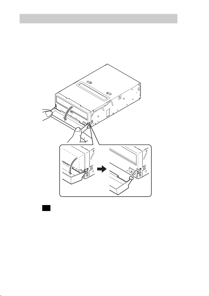
Removing the Dust Cover
1 Open the dust cover.
2 Holding the dust cover at both corners, carefully raise the
dust cover.
The dust cover hinge clips and drive bezel pins uncouple.
Note
We recommend that you use the drive with the dust cover.
19
Page 20

Operation
Location of 3 LEDs
There are three LED indications (TAPE MOTION LED, CLEANING
REQUEST LED, REPLACE TAPE LED) and an EJECT button on the
front panel of the unit.
Front Panel (for 3.5" Standard Height)
Advanced
Intelligent
Tape
TAPE
MOTION
CLEANING
REQUEST
REPLACE
TAPE
LED
EJECT button
LED Indication for Drive Status
The LED indicators are defined as follows.
LED
TAPE CLEANING REPLACE
MOTION REQUEST TAPE
Independent Independent Tape Loaded
Independent Independent Tape Access in Progress (write/read)
Independent Independent Tape Access in Progress (others)
Independent Independent Cleaning is requested
Independent Independent Cleaning is Not Completed
Independent Independent Media Error Occurred
H/W Error Occurred
on
Slow
1 pulse (0.9 sec on/0.3 sec off)
Fast
1 pulse (0.3 sec on/0.3 sec off)
Sense
20
Page 21

Drive Operation
Loading a Cartridge
Note
While setting the data cartridge, do not turn off the host computer. This
may cause a malfunction or damage data.
1 Turn on the host computer. Check that the drive’s TAPE
MOTION LED, CLEANING REQUEST LED and REPLACE
TAPE LED go off.
2 Open the dust cover.
3 Set the AIT data cartridge orientation as shown here and
insert it into the data cartridge slot.
By inserting the data cartridge to the extent, it is automatically set in
the drive and the TAPE MOTION LED lights.
Unloading a Cartridge
The cartridge can be removed from the SDX-570V and SDX-470V either in
response to a ATAPI Unload Command, or by pressing the EJECT bottom.
By pressing EJECT button, the tape is rewound and the cartridge ejected
from the slot.
21
Page 22

Write-protecting a Cartridge
Cartridges can be write-protected by sliding the tab on the back of the
cartridge. In this state, data can be read from the tape but not written onto it.
Using a Cleaning Cartridge
To keep the AIT drive in top condition, clean the head as needed using a
cleaning cartridge with the AIT logo. When the head needs cleaning, the
CLEANING REQUEST indicator lights.
How to Clean
1 Load the cleaning cartridge (SDX1-CL) into the AIT drive.
Cleaning starts automatically.
2 After about 15 seconds, cleaning will stop and the cartridge
will be ejected automatically.
Caution
Do not rewind the cleaning cartridge and reuse it. When you reach the end of
the cartridge, dispose it and buy a new cleaning cartridge with the AIT logo.
Storage Precautions
• Keep cartridges in their cases when not in the drives.
• Avoid storing cartridges in dusty locations, in direct sunlight, near heaters
or air conditioners, or in humid locations.
• Do not place cartridges on dashboards or in car storage trays.
22
Page 23

Interface Implementation
Supported ATA Commands
– ATAPI SOFT RESET (0x08)
– EXECUTE DRIVE DIAGNOSTIC (0x90)
– ATAPI PACKET COMMAND (0xA0)
– ATAPI IDENTIFY DEVICE (0xA1)
– STANDBY IMMEDIATE (0xE0)
– IDLE IMMEDIATE (0xE1)
– CHECK POWER MODE (0xE5)
– SLEEP (0xE6)
– SET FEATURE (0xEF)
Supported ATAPI Packet Commands
Mandatory ATAPI command set:
Supporting most of all SCSI commands in the AIT Tape Drive.
– ERASE
– INQUIRY
– LOAD/UNLOAD
– LOCATE
– LOG SELECT
– LOG SENSE
– MODE SELECT
– MODE SENSE
– READ
– READ POSITION
– REQUEST SENSE
– REWIND
– SPACE
– TEST UNIT READY
– WRITE
– WRITE BUFFER
– WRITE FILEMARK
23
Page 24

Specification
Product Specifications
Dimensions
3.5" 5.25"
Height 41.2 mm (1.62 in) 41.2 mm (1.62 in)
Width 101.6 mm (4.0 in) 146.0 mm (5.75 in)
Depth 155.0 mm (6.1 in) 155.0 mm (6.1 in)
Mass
SDX-570V SDX-470V
3.5" 780 g (27.5 oz.) 740 g (26.1 oz.)
5.25" 1050 g (37.0 oz.) 970 g (34.2 oz.)
Temperature and Humidity Range
Temperature
Operating 5 ˚C to 40 ˚C (∆T<10 ˚C/h)
(41 ˚F to 104 ˚F (∆T<18 ˚F/h))
Non-Operating (mech.) – 40 ˚C to 70 ˚C (∆T<20 ˚C/h)
(– 40 ˚F to 158 ˚F (∆T<36 ˚F/h))
Non-Operating (tape) – 40 ˚C to 45 ˚C (∆T<20 ˚C/h)
(– 40 ˚F to 113 ˚F (∆T<36 ˚F/h))
Humidity
Operating 20 to 80% RH, non-condensing
Non-Operating (mech.) 5 to 95% RH (∆RH<30%/h)
Non-Operating (tape) 20 to 80% RH (∆RH<30%/h)
Maximum wet bulb temperature :
26 ˚C (78.8 ˚F)
Maximum wet bulb temperature :
45 ˚C (113 ˚F)
24
Page 25

Power Requirements
SDX-570V
Voltage Max Ripple
5 V +/– 5 % 100 mVp-p 1.4 A 1.7 A
12 V +/– 10 % 150 mVp-p 0.5 A 1.3 A
SDX-470V
Voltage Max Ripple
5 V +/– 5 % 100 mVp-p 1.0 A 1.4 A
12 V +/– 10 % 150 mVp-p 0.3 A 1.4 A
Typical Maximum
Typical Maximum
Current
Current
Air-cooling Requirement
Surrounding temperature < 40 ˚C (104 ˚F)
Clean air flow is recommended to minimize the possibility of data loss.
Acer Contacts
For further information, please contact:
http://www.acer.com/
25
Page 26

本文檔包含受版權保護的專利資訊。
保留所有權利。事先未經 Acer 公司
書面許可,不得影印、拷貝本文檔的
任何部分,或將本文檔翻譯成其他語
言。
本文檔中的資訊會有改變,恕不事先
通知。
Acer 不對本文檔做任何擔保。
Acer 不對此處的錯誤負責,也不對
因設備、執行或使用本文檔而產生的
間接損失、特別損失、附帶損失或後
續損失負責。
您的 AIT TAPE DRIVE 有一個 SDX570V , SDX-470V 的機型號,它表示
符合法規認證。
該號和額定電壓及額定電流一起,位
於磁帶機型號標籤上。
VORSICHT
Für Kunden in Deutschland
Diese Ausrüstung erfüllt die
Europäischen EMC-Bestimmungen für
die Verwendung in folgender /
folgenden Umgebung(en):
•Wohngegenden
• Gewerbegebiete
• Leichtindustriegebiete
(Diese Ausrüstung erfüllt die
Bestimmungen der Norm EN55022,
Klasse B.)
26
Page 27

重要安全須知
為保證安全,使用本設備前,請詳盡
閱讀“安全說明”,並妥善保管本說
明書以備參考。
請仔細查看並遵守本設備上的或使用
說明書中所描述的所有警告標誌、防
護措施和使用說明。
使用
電源 – 本設備僅使用標籤上指明的電
源類型。如果不能確認電源類型,請
向經銷商或當地電力公司咨詢。
關於帶有三相接地型 AC 插頭的本設
備:
如果無法將插頭插入插座,請與電工
聯繫要求安裝合適的插頭。不要使接
地插頭的安全作用失效。
AC 電源線︰(僅用於 AC 電源操作本
設備時)
AC 電源線應具有可在該國使用於本
設備的安全許可或標誌。請向經銷商
或當地電力公司咨詢。
清潔 – 清潔或擦亮本設備前,應從牆
壁插座上拔下本設備。請勿使用液體
或氣霧型清潔劑清洗本設備。可使用
略微浸濕的軟布擦拭本設備的外表。
進入異物和液體 – 切勿將任何類型的
異物透過開口放入本設備,因為這些
異物可能會碰及危險的帶電體,或造
成部件短路,從而引發火災或觸電事
故。切勿使任何類型的液體濺落到本
設備上。
CT
27
Page 28

安裝
水和濕氣 – 不要在有水的地方使用帶
有電源線的本設備,如浴缸、臉盆、
廚房水槽或洗衣盆旁邊,潮濕的地下
室中或游泳池附近等。
保護電源線 – 應在不太可能被踩著或
被擠壓的地方布線,並特別注意插
頭、插座,以及電線從本設備中伸出
的地方。
附件 – 車、工作臺、三腳架、支架或
桌子上。否則,本設備可能會掉落,
給人員造成嚴重傷害,並使本設備嚴
重損壞。僅使用製造商推薦的手推
車、工作臺、三腳架、支架或桌子。
通風 – 機櫃上設置孔和開口以進行必
要的通風。為確保本設備的可靠操
作,防止本設備過熱,切勿堵塞或覆
蓋這些孔和開口。
• 切勿用布或其他材料覆蓋孔和開
口。
• 切勿將本設備置於床、沙發、毛毯
或其他類似的表面上,以免堵塞孔
和開口。
• 切勿將本設備置於密閉的空間,如
書櫥或內建的箱體中,除非提供適
當的通風條件。
維修
–
裝置損壞維修
設備,根據下列情形交給有資質的維
修人員進行維修:
• 電源線或插頭損壞或磨損時。
• 本設備被液體濺濕或有異物掉入本
設備。
• 本設備浸水或受到雨淋。
• 本設備掉落遭受嚴重的撞擊,或機
櫃受損。
• 本設備不能按使用說明正常工作。
只能調整使用說明書中所規定的控
制部件。對其他控制部件的不適當
調整會導致損壞,並經常需要有資
質的技術人員工作大量時間以使本
設備恢復正常工作。
• 本設備在性能上有明顯的改變──
表明需要進行維修。
維修 – 不要試圖擅自檢修本設備,因
為打開或取出蓋子會招致高壓或其他
的危險。
應將所有的維修工作交給有資質的維
修人員。
從牆壁插座上拔下本
28
Page 29

目錄
SDX-570V/SDX-470V 磁帶機 ........................................ 30
介紹........................................................... 31
產品特性 ................................................... 31
防護措施 ................................................... 32
安裝........................................................... 34
接頭....................................................... 34
選擇開關(DIP Switch)...................................... 35
安裝孔位 ................................................... 37
從 5.25”型號改裝為 3.5”型號 ............................... 39
方向....................................................... 40
安裝和取下防塵罩 ............................................... 41
取下防塵罩 ................................................. 43
操作........................................................... 44
三個 LED 指示燈的位置 ....................................... 44
磁帶機操作 ................................................. 45
界面應用 ....................................................... 48
支援的 ATA 指令 ............................................. 48
支援的 ATAPI Packet 指令 .................................... 48
規格........................................................... 49
產品規格 ................................................... 49
客戶聯繫 ....................................................... 50
29
Page 30

SDX-570V/SDX-470V 磁帶機
SDX-570V/SDX-470V 系列磁帶機是使用 AIT (Advanced Intelligent
Tape)的高容量資料儲存娊置。SDX-570V/SDX-470V 磁帶機經由先寫
入後讀取,錯誤更正編碼額位水準和其他特徵而達到高資料可靠性。
SDX-570V/SDX-470V 系列磁帶機儲存資料在一標準格式化稱為AIT
(Advanced Intelligent Tape)和 ALDC 格式的磁帶上。
30
Page 31

介紹
產品特性
資料儲存容量
傳輸速率
(持續的)
支援格式
緩衝記憶體
SDX-570V
80
G 位元組 未壓縮
208 G 位元組 已壓縮 *
(使用 TAIT2-80N 或
TAIT2-80C)
12 MB/s 位元組 未壓縮
(使用 AIT-E Turbo ,
AIT-1 Turbo , AIT-2 和
AIT-2 Turbo)
8 MB/s 位元組 已壓縮
(使用 AIT-1)
AIT-E Turbo , AIT-1 ,
AIT-1 Turbo , AIT-2 ,
AIT-2 Turbo
24 MB
SDX-470V
40 G 位元組 未壓縮
104 G 位元組 已壓縮 *
(使用 TAIT1-40N 或
TAIT1-40C)
6 MB/s 位元組 未壓縮
(使用 AIT-E Turbo 和
AIT-1 Turbo)
4 MB/s 位元組 已壓縮
(使用 AIT-1)
AIT-E Turbo , AIT-1 ,
AIT-1 Turbo
12 MB
* 假定壓縮比為 2.6 : 1
(記錄資料時的資料壓縮比因資料類型而有所不同。)
• 瞬間傳輸率為150
MB/s
• 標準高度 3.5”,一半高度 5.25”
• SATA 1.5
Gbps(Gen.1)
• 資料框重寫功能
• 三級錯誤更正編碼(ECC)
• 高速搜尋(一般讀 /寫速度的 120 倍)
• 隨機讀取,添加寫入
31
Page 32

防護措施
安裝
請勿將磁帶機置於下列場所︰
– 高濕度區
– 高溫區
– 有機械衝擊和震動的地方
– 陽光直射的地方
操作
• 當磁帶機運作時,請勿移動,否則可能會導致故障發生。
• 避免將磁帶機暴露於溫度突然由低變高的環境,否則可能會造成磁帶
機內部凝結水氣。如果周圍溫度突然上升而要啟動磁帶機,請在啟動
磁帶機之前要等待至少一小時。如果在溫度突然增加之後立即嘗試操
作磁帶機,則可能造成故障。
• 如果在磁帶機向磁帶寫入資料時關閉磁帶機的電源,則可能無法讀取
磁帶上的資料。無論何時開啟或關閉磁帶機的電源,先前設定的所有
參數都將丟失。
運送
• 請保留原始的包裝材料,以備日後磁帶機的安全運送。
• 移動本機之前,請務必取出資料磁帶匣。將磁帶機由電腦內取出後,
再裝於原始的包裝箱內。
32
Page 33

可用的磁帶匣
SDX-570V 可與帶有AIT-E Turbo 、AIT-1 Turbo、AIT-2 Turbo、AIT1或AIT-2 標誌的資料磁帶匣一起使用。
SDX-470V 可與帶有AIT-E Turbo 、AIT-1 Turbo 或 AIT-1 標誌的資料
磁帶匣一起使用。
註
• 請務必只使用專為AIT 設計的磁帶匣。
• 請勿在本系統中使用非AIT 磁帶匣,否則會損壞AIT 磁帶機。儘管市
售的8 mm 視訊磁帶外觀與AIT 磁帶匣相似,但二者規格完全不同,
因此不能使用。
33
Page 34

安裝
接頭
下圖用於SDX-570V 磁帶機。
SATA
電源接頭(*1)
注意
請勿同時使用SATA電源接頭(*1)和傳統電源接頭(*2)。同時使用兩個接頭可能會使
系統損壞。
SATA
信號接頭
傳統電源接頭(*2)
4 3 2 1
5V GND GND 12V
34
Page 35

選擇開關(DIP Switch)
DIP 開關位置
預設值
ON
OFF
12345678
DIP 開關
1 磁帶機模式(OFF)
2 磁帶機模式(OFF)
3 磁帶機模式(OFF)
4 磁帶機模式(OFF)
5保留(OFF)
6 定期請求清潔(ON)
7DC控制(1)(ON)
8DC控制(2)(OFF)
請求清潔模式
可由DIP 開關開啟定期請求清潔功能。
35
Page 36

1 磁帶機模式
ON
OFF
12345678
2 磁帶機模式
3 磁帶機模式
4 磁帶機模式
5保留
6 定期請求清潔(ON)
7DC控制(1)
8DC控制(2)
當開關“6”撥在“ON ”時,“請求清潔”功能開啟。該功能開啟後,
每操作100小時,前面面板上的“CLEANING REQUEST (請求清潔)”指
示燈亮起。
當該指示燈亮起時,請用磁頭清潔匣清潔磁帶機。
註
要使磁帶機在易受灰塵或其他污染物影響的環境中保持最佳狀態,建議
始終開啟“請求清潔”功能。
資料壓縮控制 DIP 開關
資料的壓縮是經由DIP 開關的選擇。當DIP 開關的位置“7”[DC 控制(1)]
撥在“ON ”時,啟動資料壓縮的功能,當DIP 開關的位置“8”[DC 控制
(2)]撥 在“ ON ”時,解除由主電腦控制。
36
Page 37

安裝孔位
下圖用於SDX-570V 磁帶機。
3.5”標準高度的安裝孔位
_
+
4.8 0.5mm
_
+
[0.19" 0.02"]
_
+
41.2 0.5mm
_
+
[1.62" 0.02"]
6-M3 (depth 2.5mm [0.10"] max.)
6-M3 (depth 2.5mm [0.10"] max.)
_
+
_
+
_
+
_
+
90.0 0.3mm [3.54" 0.01"]
60.0 0.3mm
[2.36" 0.01"]
_
+
_
+
21.0 0.3mm
[0.83" 0.01"]
_
+
_
+
7.4 0.6mm [0.29" 0.02"]
_
+
_
+
9.8 0.6 mm
[0.39" 0.02"]
8.3±0.5 mm (0.33±0.02 in)
_
+
_
+
155.0 0.5mm [6.10" 0.02"]
96.1 mm (3.78 in)
_
+
94.0 0.5mm [3.70" 0.02"]
_
+
101.6 0.5mm [4.00" 0.02"]
_
+
_
+
_
+
_
+
42.0 0.3mm
[1.65" 0.01"]
70.0 0.3mm [2.76" 0.01"]
_
+
_
+
_
+
_
+
31.0 0.3mm
[1.22" 0.01"]
37
Page 38

5.25”高度的安裝孔位
8.3±0.5 mm
(0.33±0.02 in)
146±0.5 mm
(5.75±0.02 in)
96.1 mm
(3.78 in)
7.0mm
[0.28"]
_
+
_
+
79.2 0.3mm [3.12" 0.01"]
_
+
9.9 0.5mm
_
[0.39" 0.02"]
+
_
+
21.8 0.5mm
_
+
[0.86" 0.02"]
_
+
41.2 0.5mm
_
+
[1.62" 0.02"]
6-M3
_
+
_
+
_
+
_
+
_
+
79.2 0.3mm [3.12" 0.01"]
_
+
_
+
47.5 0.3mm
[1.87" 0.01"]
_
+
_
+
_
+
155.0 0.5mm [6.10" 0.02"]
42.0 0.3mm
[1.65" 0.01"]
70.0 0.3mm [2.76" 0.01"]
_
+
_
+
_
+
_
+
9.8 0.6 mm
[0.39" 0.02"]
_
+
7.4 0.6mm [0.29" 0.02"]
_
+
31.0 0.3mm [1.22" 0.01"]
_
+
94.0 0.5mm [3.70" 0.02"]
_
+
139.6 0.5mm [5.50" 0.02"]
_
+
146.0 0.5mm [5.75" 0.02"]
_
+
149.0 0.5mm [5.87" 0.02"]
_
+
_
+
_
+
_
+
4-M3
_
+
_
+
79.2 0.3mm [3.12" 0.01"]
_
+
_
+
47.5 0.3mm
[1.87" 0.01"]
38
Page 39

從 5.25”型號改裝為 3.5”型號
您可以自己將 5.25”型號改裝為 3.5”型號。
1 擰掉兩側側板上的 2 個螺絲。
2 取下側板。
側板(左)
側板(右)
39
Page 40

方向
10°10
10°10
°
10
°
10
°
°
10
°
10
°
40
Page 41

安裝和取下防塵罩
1 將防塵罩的鉸鏈夾(每側各一個)與磁帶機前蓋上的銷針對
準。
• 確定防塵罩的位置,使防塵罩背面的磁鐵 * 面朝磁帶機前蓋。
*
磁鐵不會影響磁帶匣中的磁帶。
• 如下圖所示的某一角度抓住防塵罩,將鉸鏈夾裝在前蓋銷針的
頂端,確定鉸鏈夾的位置使其托住銷針。
41
Page 42

2 以某一角度輪流按壓兩側,直至聽見鉸鏈夾到位的“卡嗒”
聲。
注意
不要從正面水平方向擠壓防塵罩,否則會使防塵罩破損。
3 關閉防塵罩
42
到此結束防塵罩的安裝工作。
Page 43

取下防塵罩
1 打開防塵罩
2 抓住防塵罩的兩角,將防塵罩小心抬起。
防塵罩鉸鏈夾和磁帶機前蓋銷針分離。
註
建議使用帶有防塵罩的磁帶機。
43
Page 44

操作
三個 LED 指示燈的位置
磁帶機前面面板有三個LED 指示燈(TAPE MOTION LED (磁帶運轉指示
燈)、CLEANING REQUEST LED (請求清潔指示燈)和REPLACE TAPE LED
(更換磁帶指示燈))以及一個退出鍵EJECT 。
3.5”標準高度的前面面板
Advanced
Intelligent
Tape
TAPE
MOTION
CLEANING
REQUEST
REPLACE
TAPE
LED
磁帶機 LED 指示燈
LED 指示燈定義如下
LED
TAPE CLEANING REPLACE
MOTION REQUEST TAPE
無關聯 無關聯 已裝入磁帶
無關聯 無關聯 正在訪問磁帶(寫入 / 讀取)
無關聯 無關聯 正在訪問磁帶(其他)
無關聯 無關聯 請求清潔
無關聯 無關聯 清潔未完成
無關聯 無關聯 發生介質錯誤
發生 H/W 錯誤
亮
慢
1脈衝(0.9 秒亮 /0.3 秒滅)
快
1脈衝(0.3 秒亮 /0.3 秒滅)
EJECT 鍵
意義
44
Page 45

磁帶機操作
裝入磁帶匣
註
安裝資料磁帶匣時,請勿關閉主電腦的電源。否則會造成故障或損壞資
料。
1 打開基本處理器的電源,檢查磁帶機的 TAPE MOTION LED(磁
帶運轉指示燈)、 CLEANING REQUEST LED(請求清潔指示燈)
和 REPLACE TAPE LED(更換磁帶指示燈)是否已經熄滅。
2 打開防塵罩。
3 按此處所示的方向安放 AIT 資料磁帶匣,將其插入磁帶匣插
槽。
將磁帶匣一直插入,磁帶匣將被自動裝入磁帶機,此時, TAPE
MOTION LED 亮起。
45
Page 46

取出磁帶匣
可透過SCSI 取出命令或按EJECT (退出)鍵從SDX-570V 和SDX-470V
取出磁帶匣。
按EJECT (退出)鈕,磁帶倒繞,磁帶匣從插槽內退出。
磁帶匣寫入保護
將磁帶匣背面的滑動開關撥向箭頭方向,使其進入寫入保護狀態,在這
種狀態下,資料只可以由磁帶讀取而不能寫入。
用指甲將開關推向箭頭所指的方向以防
止寫入或意外刪除資料。
將開關扳回原始位置以恢複寫入功能。
使用清潔磁帶匣
為保持AIT 磁帶機的最佳狀態,請根據需要使用帶有AIT 標誌的磁頭清
潔匣清潔磁頭。當磁頭需要清潔時,CLEANING REQUEST 指示燈亮起。
如何清潔
1 將清潔匣(SDX1-CL)裝入 AIT 磁帶機。清潔自動開始。
2 約15秒鐘後,清潔停止,磁帶匣自動退出。
注意
請勿倒繞磁頭清潔匣並重新使用。當磁頭清潔匣到達盡頭時,請將
其丟棄並購買帶有AIT 標誌的新清潔匣。
46
Page 47

存放須知
• 不使用磁帶匣時,應將其保存在存放盒中。
• 應避免將磁帶匣存放在多塵的地方、直射的陽光下、加熱器或空調器
附近,以及潮濕的地方。
• 請勿將磁帶匣放置在儀表板或汽車的儲存盤中。
47
Page 48

界面應用
支援的 ATA 指令
– ATAPI SOFT RESET (0x08)
– EXECUTE DRIVE DIAGNOSTIC (0x90)
– ATAPI PACKET COMMAND (0xA0)
– ATAPI IDENTIFY DEVICE (0xA1)
– STANDBY IMMEDIATE (0xE0)
– IDLE IMMEDIATE (0xE1)
– CHECK POWER MODE (0xE5)
– SLEEP (0xE6)
– SET FEATURE (0xEF)
支援的 ATAPI Packet 指令
強制性 ATAPI 指令設定︰
支援AIT 磁帶機中的大多數 SCSI 指令。
– ERASE
– INQUIRY
– LOAD/UNLOAD
– LOCATE
– LOG SELECT
– LOG SENSE
– MODE SELECT
– MODE SENSE
– READ
– READ POSITION
– REQUEST SENSE
– REWIND
– SPACE
– TEST UNIT READY
– WRITE
–WRITE BUFFER
– WRITE FILEMARK
48
Page 49

規格
產品規格
體積
3.5" 5.25"
高度 41.2 mm (1.62 in) 41.2 mm (1.62 in)
寬度 101.6 mm (4.0 in) 146.0 mm (5.75 in)
厚度 155.0 mm (6.1 in) 155.0 mm (6.1 in)
重量
SDX-570V SDX-470V
3.5" 780 g (27.5 oz.) 740 g (26.1 oz.)
5.25" 1050 g (37.0 oz.) 970 g (34.2 oz.)
溫度和濕度範圍
溫度
工作中 5 ℃到 40 ℃(溫度變化 < 10 ℃/h)
未工作中(機械結構) -40 ℃到 70 ℃(溫度變化 < 20 ℃/h)
未工作中(磁帶) -40 ℃到 45 ℃(溫度變化 < 20 ℃/h)
濕度
工作中 20 到 80% RH ,不結霜
最大濕球溫度﹕26
未工作中(機械結構) 5 到 95% RH(濕度變化 < 30%/h)
最大濕球溫度﹕45
未工作中(磁帶) 20 到 80% RH(濕度變化 < 30%/h)
℃
℃
49
Page 50

電源要求
SDX-570V
電壓 最大漣波
5 V +/– 5% 100 mVp-p 1.4 A 1.7 A
12 V +/– 10% 150 mVp-p 0.5 A 1.3 A
SDX-470V
電壓 最大漣波
5 V +/– 5% 100 mVp-p 1.0 A 1.4 A
12 V +/– 10% 150 mVp-p 0.3 A 1.4 A
常態 最大
常態 最大
電流
電流
空氣冷卻要求
周圍溫度 <40 ℃
建議在清新流動的空氣環境中使用,將資料丟失的可能性減小到最低限度。
客戶聯繫
如需進一步相關訊息,請參考以下網址:
http://www.acer.com/
50
Page 51

本文包含受版权保护的专利信息。
版权所有。未经 Acer 公司书面同意
不得拍摄、复制本文的任何部分或将
其翻译成其他语言。
本文中的信息如有更改,恕不通知。
Acer 公司不承诺任何有关本文档的
保证。
Acer 公司不对本文档中包含的错误
以及本文档的供应、履行或使用相关
的间接、特殊、意外或导致的损害负
责。
您的 AIT TAPE DRIVE 配有型号
SDX-570V/SDX-470V,该型号通
过规范达标认证。
驱动器的型号标签上列出了该号码以
及额定电压和电流。
CS
51
Page 52

重要安全说明
为了您的安全,请在使用本装置前通
读这些安全指示,并妥善保存本手册
以备将来参考。
请认真并始终遵守本装置或操作说明
上的所有警告、事先注意事项和指
示。
使用
电源 – 本装置只能使用标牌上标识的
电源类型。如果不能确定电源的类
型,请咨询经销商或当地电力公司。
对于带三线接地型 AC 插头的型号:
如果不能把插头插入插座,请和电工
联系以安装合适的插头。请勿让接地
插头的安全功效作废。
AC电源线:(只适用于使用AC电源
操作的型号)
AC电源线必须具备使用地国家的相
应安全许可或标志。请咨询经销商或
当地电力公司。
清洁 – 在清洁或给本装置上光前,请
从墙壁插座拔出电源插头。请勿使用
液体清洁剂或气雾清洁剂。请用蘸了
少量水的布清洁本装置外壳。
异物和液体进入 – 切勿从本装置的孔
槽中塞入任何异物,因为它们可能碰
到高压点或使部件短路,从而导致火
灾或触电。切勿让任何液体溅到本装
置上。
52
Page 53

安装
水和潮湿 – 请勿在水边使用电源线操
作本装置-例如,浴缸、洗脸盆、厨
房水槽、洗衣水池、潮湿的地下室或
游泳池等附近。
电源线保护 – 请妥善布置电源线,使
它不会被踩到或被放在上面或靠着的
东西夹住。请特别注意插头、插座以
及电线和本装置的结合处。
补充 – 请勿将本装置放在不稳定的车
子、台子、三脚架、托架或桌子上,
否则本装置可能掉落,导致儿童或成
人严重受伤以及本装置严重受损。请
只使用制造商推荐的车子、台子、三
脚架、托架或桌子。
通风 – 机壳上的槽和孔用于必要的通
风。为确保本装置的正常工作并防止
过热,切勿堵塞或覆盖这些槽和孔。
• 切勿用布或其它材料覆盖这些槽和
孔。
• 切勿把本装置放在床、沙发、垫子
或其它类似物体上,以免堵塞这些
槽和孔。
• 切勿把本装置放在诸如书柜、壁柜
等封闭的空间里,除非提供了适当
的通风。
维修
故障维修 – 在下列情况下,请从墙壁
插座拔下电源插头并请合格的维修人
员进行维修。
• 当电源线或插头损坏或磨损时。
• 如果液体溅入本装置或异物掉入本
装置。
• 如果本装置淋雨或进水。
• 如果本装置因掉落而受到强烈震
动,或外壳已损坏。
• 如果虽按操作说明进行操作,本装
置工作不正常。请只调节操作说明
指定的控制钮。错误的调节其它控
制钮可能导致装置损坏,同时经常
导致需要合格的技术人员进行大量
的修理工作,才能使本装置恢复正
常。
• 当本装置的性能发生显著变化 - 这
时表示需要维修。
维修 – 请勿自行维修本装置,因为打
开或取下外壳可能使您暴露在高压
下,或受到其它伤害。务必请合格的
维修人员进行所有的维修。
53
Page 54

目录
SDX-570V/SDX-470V 磁带驱动器 ............................................................. 55
介绍................................................................................................................56
产品特性 ................................................................................................ 56
事先注意事项 ......................................................................................... 57
安装................................................................................................................59
连接器 ....................................................................................................59
可选开关(DIP 开关)............................................................................ 60
安装孔 ....................................................................................................62
从5.25" 型号重新配置为 3.5" 型号 ....................................................... 64
方向........................................................................................................ 65
安装和拆除防尘盖 ......................................................................................... 66
安装防尘盖............................................................................................. 66
拆除防尘盖............................................................................................. 68
操作................................................................................................................69
3个LED 的位置 ..................................................................................... 69
驱动器操作............................................................................................. 70
接口实现 ........................................................................................................ 73
支持的 ATA 命令 ..................................................................................73
支持的 ATAPI 包命令 ..........................................................................73
规格................................................................................................................74
产品规格 ................................................................................................ 74
联系方式 ........................................................................................................ 75
54
Page 55

SDX-570V/SDX-470V 磁带驱动器
SDX-570V/SDX-470V 驱动器是使用高级智能磁带(AIT)技术的高容
量数据存储装置。SDX-570V/SDX-470V驱动器通过Read-After-Write
附加级纠错编码和其他功能实现了高数据可靠性。
SDX-570V/SDX-470V
ALDC 格式将数据存储在磁带上。
驱动器使用 AIT(高级智能磁带)标准格式和
55
Page 56

介绍
产品特性
SDX-570V
数据容量
传输速率
(持续)
支持的格式
缓冲区内存
* 假定压缩率为 2.6 : 1
(压缩率根据数据类型而变)
80 G 未压缩
208 G 压缩*
(使用 TAIT2-80N 或
TAIT2-80C)
12 MB/s 未压缩
(使用 AIT-E Turbo、
AIT-1 Turbo、AIT-2 和
AIT-2 Turbo)
8 MB/s 压缩
(使用 AIT-1)
AIT-E Turbo、AIT-1、
AIT-1 Turbo、AIT-2、
AIT-2 Turbo
24 MB
• 突发传输速率 150 MB/s
• 3.5" 标准高度,5.25" 半高度
• SATA 1.5 Gbps (Gen.1)
• 帧重写功能
• 第三级纠错编码(ECC)
• 高速搜索(正常读 / 写速度的 120 倍)
• 随机读,追加写
SDX-470V
40 G 未压缩
104 G 压缩*
(使用 TAIT1-40N 或
TAIT1-40C)
6 MB/s 未压缩
(使用 AIT-E Turbo 和
AIT-1 Turbo)
4 MB/s 压缩
(使用 AIT-1)
AIT-E Turbo、AIT-1、
AIT-1 Turbo
12 MB
56
Page 57

事先注意事项
安装
避免将驱动器置于下列环境:
– 高湿度
– 高温
– 机械撞击或震动
– 阳光直射
操作
• 请勿在驱动器工作时移动本装置,否则可能发生故障。
• 避免使驱动器暴露在从低温到高温急剧变化的环境中,否则可能使驱
动器内部产生结露。如果当驱动器开启时周围环境温度将突然上升,
请等待至少一小时再开启驱动器。如果您试图在温度急剧上升后立即
操作驱动器,可能会出现故障。
• 当驱动器正在写入时关闭电源可能导致磁带变成不可读。驱动器电源
再开启时,所有以前的参数将丢失。
运输
• 请保留原始包装材料,以便运输驱动器。
• 在移动驱动器之前必须取出数据盒式磁带。将驱动器从计算机上卸下
后,应将驱动器放入原始包装内。
57
Page 58

可用盒式磁带
SDX-570V 可与带有 AIT-E Turbo、AIT-1 Turbo、AIT-2 Turbo、
AIT-1 或 AIT-2 标志的数据盒式磁带一同使用。
SDX-470V 可与带有 AIT-E Turbo、AIT-1 Turbo 或 AIT-1 标志的
数据盒式磁带一同使用。
注意
• 务必仅使用专为 AIT 设计的数据盒式磁带。
• 请勿在本系统内使用除 AIT 盒式磁带以外的其他磁带。否则,会损
坏 AIT 驱动器。尽管市售的 8 mm 盒式录像带与 AIT 盒式磁带外观
相似,但二者规格完全不同,因此不能使用盒式录像带。
58
Page 59

安装
连接器
下图适用于 SDX-570V。
SATA电源连接器(*1)
注意
请勿同时使用 SATA 电源连接器(*1)和 Legacy 电源连接器(*2)。
否则,可能导致系统损坏。
SATA信号连接器
Legacy电源连接器(*2)
4 3 2 1
5V GND GND 12V
59
Page 60

可选开关(DIP 开关)
DIP 开关位置
默认
ON
OFF
12345678
DIP 开关
1驱动器模式(OFF/关)
2驱动器模式(OFF/关)
3驱动器模式(OFF/关)
4驱动器模式(OFF/关)
5保留(OFF/关)
6 定期清洁要求(ON/ 开)
7DC控制(1)(ON/ 开)
8DC控制(2)(OFF/ 关)
60
Page 61

清洁要求模式
可用 DIP 开关启用定期清洁要求。
ON
OFF
12345678
1 驱动器模式
2 驱动器模式
3 驱动器模式
4 驱动器模式
5保留
6 定期清洁要求(ON)
7DC控制(1)
8DC控制(2)
当开关 6 处于“ON”时,清洁要求模式被启用。当该模式启用后,每
工作 100 小时后,前面板上的“CLEANING REQUEST”LED 亮起。
LED 亮起时,可使用磁头清洁盒式磁带清洁驱动器。
注
要使驱动器在易受灰尘或其他污染物影响的环境中保持最佳工作状态,建议将清洁
要求模式处于启用状态。
数据压缩控制 DIP开关
可通过 DIP 开关选择数据压缩。当位置 7 [DC 控制(1)]处于“开”时,
数据压缩启用。当位置 8 [DC 控制(2)]处于“开”时,主机控制被禁止。
61
Page 62

安装孔
下图适用于 SDX-570V 型号。
对于 3.5" 标准高度
_
+
4.8 0.5mm
_
+
[0.19" 0.02"]
_
+
41.2 0.5mm
_
+
[1.62" 0.02"]
6-M3 (depth 2.5mm [0.10"] max.)
6-M3 (depth 2.5mm [0.10"] max.)
_
+
_
+
_
+
_
+
90.0 0.3mm [3.54" 0.01"]
60.0 0.3mm
[2.36" 0.01"]
_
+
_
+
21.0 0.3mm
[0.83" 0.01"]
_
+
_
+
7.4 0.6mm [0.29" 0.02"]
_
+
_
+
9.8 0.6 mm
[0.39" 0.02"]
8.3±0.5 mm (0.33±0.02 in)
_
+
_
+
155.0 0.5mm [6.10" 0.02"]
96.1 mm (3.78 in)
_
+
94.0 0.5mm [3.70" 0.02"]
_
+
101.6 0.5mm [4.00" 0.02"]
_
+
_
+
_
+
_
+
42.0 0.3mm
[1.65" 0.01"]
70.0 0.3mm [2.76" 0.01"]
_
+
_
+
_
+
_
+
31.0 0.3mm
[1.22" 0.01"]
62
Page 63

对于 5.25" 半高度
8.3±0.5 mm
(0.33±0.02 in)
146±0.5 mm
(5.75±0.02 in)
96.1 mm
(3.78 in)
7.0mm
[0.28"]
_
+
_
+
79.2 0.3mm [3.12" 0.01"]
_
+
9.9 0.5mm
_
[0.39" 0.02"]
+
_
+
21.8 0.5mm
_
+
[0.86" 0.02"]
_
+
41.2 0.5mm
_
+
[1.62" 0.02"]
6-M3
_
+
_
+
_
+
_
+
_
+
79.2 0.3mm [3.12" 0.01"]
_
+
_
+
47.5 0.3mm
[1.87" 0.01"]
_
_
+
_
+
155.0 0.5mm [6.10" 0.02"]
42.0 0.3mm
70.0 0.3mm [2.76" 0.01"]
_
+
_
_
+
_
+
9.8 0.6 mm
[0.39" 0.02"]
_
+
7.4 0.6mm [0.29" 0.02"]
_
+
[1.65" 0.01"]
+
94.0 0.5mm [3.70" 0.02"]
139.6 0.5mm [5.50" 0.02"]
146.0 0.5mm [5.75" 0.02"]
149.0 0.5mm [5.87" 0.02"]
+
31.0 0.3mm [1.22" 0.01"]
4-M3
_
+
_
+
79.2 0.3mm [3.12" 0.01"]
_
+
_
+
47.5 0.3mm
[1.87" 0.01"]
_
+
_
+
_
+
_
+
_
+
_
+
_
+
_
+
63
Page 64

从 5.25" 型号重新配置为 3.5" 型号
您可以自己将 5.25" 型号重新配置为 3.5" 型号。
1 松开两侧边条上各自的两个螺丝。
2 卸下侧边条。
侧边条(左)
侧边条(右)
64
Page 65

方向
10°10
10°10
°
10
°
10
°
°
10
°
10
°
65
Page 66

安装和拆除防尘盖
安装防尘盖
1 将防尘盖的铰接销(一边一个)与驱动器前盖上的销孔对齐。
• 防尘盖的放置应该使该盖背面的磁体 * 面向驱动器前盖。
*
该磁体不会影响磁带。
• 如下图所示以一个角度握住防尘盖,将铰接销装入前盖销孔的
顶部,使铰接销挂在销孔上。
66
Page 67

2 从一个角度依次按压两端,直到您听见铰接销到位的“喀哒”
声。
注意
不要从前面水平地按压防尘盖。这样可能导致防尘盖断裂。
3 关上防尘盖。
这样即完成了防尘盖的安装。
67
Page 68
拆除防尘盖
1 打开防尘盖。
2 握住防尘盖的两端,小心地抬起防尘盖。
防尘盖铰接销与驱动器前盖销孔脱离。
68
注
建议使用防尘盖。
Page 69

操作
3个LED 的位置
该装置的前面板上有三个 LED 指示灯(TAPE MOTION LED,
CLEANING REQUEST LED, REPLACE TAPE LED)和一个
EJECT 按钮。
前面板(3.5" 标准高度)
Advanced
Intelligent
Tape
TAPE
MOTION
CLEANING
REQUEST
REPLACE
TAPE
LED
LED 驱动器状态指示灯
LED 指示灯定义如下
LED
TAPE CLEANING REPLACE
MOTION REQUEST TAPE
无关 无关 磁带已装载
无关 无关 磁带访问进行中(写/读)
无关 无关 磁带访问进行中(其他)
无关 无关 请求清洁
无关 无关 清洁未完成
无关 无关 出现介质错误
出现H/W错误
亮
慢闪烁
一个脉冲(0.9秒亮/0.3秒灭)
快闪烁
一个脉冲(0.3秒亮/0.3秒灭)
含义
69
Page 70

驱动器操作
装载磁带
注
当装入数据磁带时,请勿关闭主机电源。否则可能导致故障或损坏数
据。
1 开启主机电源。检查驱动器的 TAPE MOTION LED、
CLEANING REQUEST LED 和 REPLACE TAPE LED 指
示灯是否熄灭。
2 打开防尘盖。
3 按如图所示的方向将 AIT 数据磁带插入数据磁带槽。
70
插入数据磁带至一定深度时,它将自动装入驱动器并且 TAPE
MOTION LED 指示灯亮。
Page 71

卸载磁带
可通过 ATAPI Unload 命令或通过按 EJECT 按钮,将磁带从SDX-570V
和 SDX-470V 中卸载。
按 EJECT 按钮后,磁带倒绕,盒式磁带从槽中弹出。
设置磁带写保护
通过滑动盒式磁带背面的凸起可以设置磁带写保护。在该状态下,磁带
可以读但不能写入。
用指甲按箭头方向推动开关,以保护磁带不被写
入或意外擦除。
将开关置回原始位置即可重新进行写入操作。
71
Page 72

使用清洁带
为了使 AIT 驱动器保持在最佳状态,请使用带有 AIT 标志的磁头清洁
带按需要清洁磁头。当磁头需要清洁时,CLEANING REQUEST 指
示灯亮。
如何清洁
1 将清洁带(SDX1-CL)装入 AIT 驱动器。即自动开始清洁。
2 大约 15 秒钟以后,清洁将停止并且磁带自动弹出。
注
请勿倒回清洁带并再次使用。当用至清洁带末端时,请将其丢弃并购买
带有 AIT 标志的新的清洁带。
存储事先注意事项
• 当磁带不在驱动器中时,请将其放在磁带盒中。
• 避免将磁带存放在积满灰尘、阳光直射、靠近加热器或空调、或者潮
湿的地方。
• 请勿将磁带放在汽车的仪表板或储物盘上。
72
Page 73

接口实现
支持的 ATA 命令
支持的 ATA 命令:
– ATAPI SOFT RESET(ATAPI 软复位) (0x08)
– EXECUTE DRIVE DIAGNOSTIC(执行驱动器诊断) (0x90)
– ATAPI PACKET COMMAND(ATAPI 包命令) (0xA0)
– ATAPI IDENTIFY DEVICE(ATAPI 识别驱动器) (0xA1)
– STANDBY IMMEDIATE(立即待机) (0xE0)
– IDLE IMMEDIATE(立即等待) (0xE1)
– CHECK POWER MODE(检查电源模式) (0xE5)
– SLEEP(睡眠) (0xE6)
– SET FEATURE(设置功能) (0xEF)
支持的 ATAPI 包命令
必备 ATAPI 命令集:
支持 AIT 磁带机中的大多数 SCSI 指令。
– ERASE(擦除)
– INQUIRY(查询)
– LOAD/UNLOAD(装载 / 卸载)
– LOCATE(定位)
– LOG SELECT(日志选择)
– LOG SENSE(日志检测)
– MODE SELECT(模式选择)
– MODE SENSE(模式检测)
– READ(读)
– READ POSITION(读取位置)
– REQUEST SENSE(请求检测)
– REWIND(倒带)
– SPACE(空白)
– TEST UNIT READY(测试装置就绪)
– WRITE(写)
– WRITE FILEMARK(写文件标记)
– WRITE BUFFER(写缓冲区)
73
Page 74

规格
产品规格
尺寸
3.5" 5.25"
高度 41.2 mm 41.2 mm
宽度 101.6 mm 146.0 mm
深度 155.0 mm 155.0 mm
重量
SDX-570V SDX-470V
3.5" 780 g 740 g
5.25" 1050 g 970 g
温度和湿度范围
温度
工作时 5 ℃至40 ℃ (∆T<10 ˚C/h)
不工作(装置) -40 ℃至70 ℃ (∆T<20 ˚C/h)
不工作(磁带) -40 ℃至45 ℃ (∆T<20 ˚C/h)
湿度
工作时 20%至80% 相对湿度,无结露
最高湿球温度计温度 : 26 ℃
不工作(装置) 5至95%相对湿度 (∆RH<30%/h)
最高湿球温度计温度 : 45 ℃
不工作(磁带) 20至80%相对湿度 (∆RH<30%/h)
74
Page 75

电源要求
SDX-570V
电压 最大波动
5 V +/– 5% 100 mVp-p 1.4 A 1.7 A
12 V +/– 10% 150 mVp-p 0.5 A 1.3 A
SDX-470V
电压 最大波动
5 V +/– 5% 100 mVp-p 1.0 A 1.4 A
12 V +/– 10% 150 mVp-p 0.3 A 1.4 A
典型 最大
典型 最大
电流
电流
空气冷却要求
环境温度 <40 ℃
推荐使用洁净的气流以使数据丢失的可能性最小。
联系方式
更详细的信息,请联系:
http://www.acer.com/
75
Page 76

Printed in Belgium
 Loading...