

AIT Drive
User’s Guide
GB
CT
SDX-400C

This document contains proprietary
information which is protected by
copyright.
All rights reserved. No part of this
document may be photocopied,
reproduced or translated to another
language without prior written consent
of Acer.
The information contained in this
document is subject to change without
notice.
Acer MAKES NO WARRANTY OF
ANY KIND WITH REGARD TO
THIS DOCUMENT.
Acer shall not be liable for error
contained herein, indirect, special,
incidental or consequential damages in
connection with the furnishing,
performance or use of this document.
VORSICHT
Diese Ausrüstung erfüllt die
Europäischen EMC-Bestimmungen für
die Verwendung in folgender /
folgenden Umgebung(en):
• Wohngegenden
• Gewerbegebiete
• Leichtindustriegebiete
(Diese Ausrüstung erfüllt die
Bestimmungen der Norm EN55022,
Klasse B.)
Contents
Introduction ....................................... 4
Product Features ........................4
Precautions ................................5
Installation ......................................... 7
SCSI Connection/Setting the
SCSI ID .................................7
Option Switches (DIP Switch) ..8
Mounting Holes........................9
Remodeling from 5.25" Model
to 3.5" Model .......................11
Orientation...............................12
Operation .........................................13
Location of 3 LEDs .................13
LED Indication for Drive
Status ...................................14
Drive Operation....................... 15
Emergency Tape Removal
Procedure .............................16
Interface Implementation................. 19
Supported SCSI Messages ...... 19
Supported SCSI Commands.... 19
Specification ....................................20
Product Specifications............. 20
Acer Contacts .................................. 22
2

SDX-400C Tape Drive
The SDX-400C drive is a high capacity data storage device using
Advanced Intelligent tape AIT (Advanced Intelligent Tape) technology.
The SDX-400C drive achieves high data reliability through Read-AfterWrite, an additional level of Error Correction Code, and other features.
The SDX-400C drive stores data on tape using a standard format called
AIT and ALDC formats.
GB
3

Introduction
Product Features
SDX-400C *
Data Capacity
Transfer Rate (sustained)
* Data compression function is available with SDX-400C.
• Supported Format : AIT-1 (Not support AIT-2 format)
• Burst Transfer Rate
– 12 MBytes/sec Asynchronous
– 40 MByte/sec Synchronous
• Large 10 M Byte Buffer Memory
• 3.5” form factor, 5.25” from factor
• Embedded SCSI Interface
(ULTRA/WIDE and LVD/SE (single-ended) model (SDX-400C))
• Supports Variable or Fixed Record Length
• Supports SCSI Disconnection/Arbitration
• Frame Rewrite Function
• Three levels of Error Correction Code (ECC)
• High Speed search (120 times normal Read/Write speed)
• Random Read, Append Write
35 GByte capacity (with AIT-1 230 m tape)
(approximately 70 GByte to 105 GByte with Data
Compression)
4 MByte/sec
(approximately 8 MByte/sec to 12 MByte/sec with
Data Compression)
4

Precautions
Installation
Avoid placing the drive in a location subject to:
– high humidity
– high temperature
– mechanical shock and vibration
– direct sunlight
Operation
• Do not move the drive while it is operating. It may cause malfunction.
• Avoid exposing the drive to sudden changes from a low to high in
temperature. This may cause water condensation to collect inside the
drive. If the ambient temperature should suddenly rise while the drive is
turned on , wait at least one hour before turning on the drive. If you
attempt to operate the drive immediately after a sudden increase in
temperature, a malfunction may occur.
• Turning off the power to the drive while it is writing to tape may cause
the tape to become unreadable. All previously negotiated parameters will
be lost, whenever power to the drive is cycled.
Transportation
• Keep the original packing materials to facilitate transportation of the
drive.
• Always remove the tape before moving the drive. After removing the
drive from the computer, repack the drive into its original packing.
5
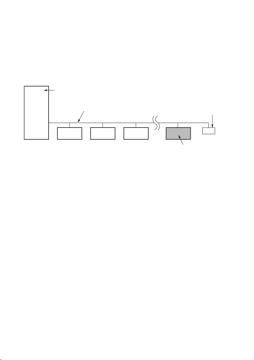
Notice of SCSI Termination
r
The SDX-400C conforms to the Microsoft PC97 standard which requires
the internal (naked) drive to be terminated with an external terminator.
Microsoft PC97 SCSI requirements
SCSI peripherals must not terminate the bus. Both internal and external
cable ends are instead terminated by plug-in connectors.
Host Computer Wide SCSI
68p cable
Exapmle of SCSI set-up
Terminato
This drive
6
Installation
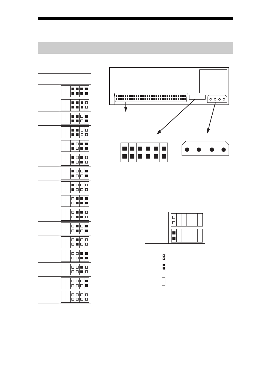
SCSI Connection/Setting the SCSI ID
SCSI ID
210
SCSI ID
0
1
P.D.
N.C.
3
10
11
12
13
14
2
3
4
5
SCSI 68pin Connector
Jumpers
Power Connector
5 V
GND GND 12 V
1234
6
SCSI ID 3
SCSI ID 2
SCSI ID 1
7
Parity Disable
8
No Connection
Parity
SCSI ID 0
9
Disable
Enable
Note := = CLOSED/Jumper
OPEN/Jumper not
installed
Don’t care
15
Parity Disable Jumper
Parity check function can be disabled by Jumper. Parity check is disabled
while left end jumper is installed. Parity generate function is always
enabled.
7
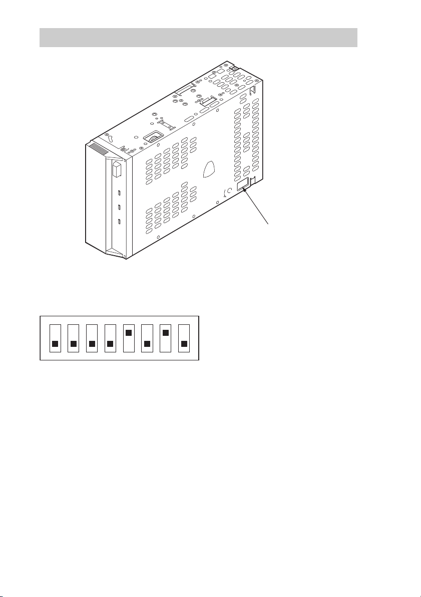
Option Switches (DIP Switch)
DIP Switch Positions
DIP Switch
ON
12345678
1 Reserved (OFF)
2 Reserved (OFF)
3 Reserved (OFF)
4 Reserved (OFF)
5 Terminator Power (ON)
6 Reserved (OFF)
7 DC Control (1) (ON)
8 DC Control (2) (OFF)
Data Compression Control DIP switch
Data compression can be selected by DIP switches. Data compression is
enabled while position 7 [DC Control (1)] is ON. Control by host can be
disabled when position 8 [DC Control (2)] is ON.
8
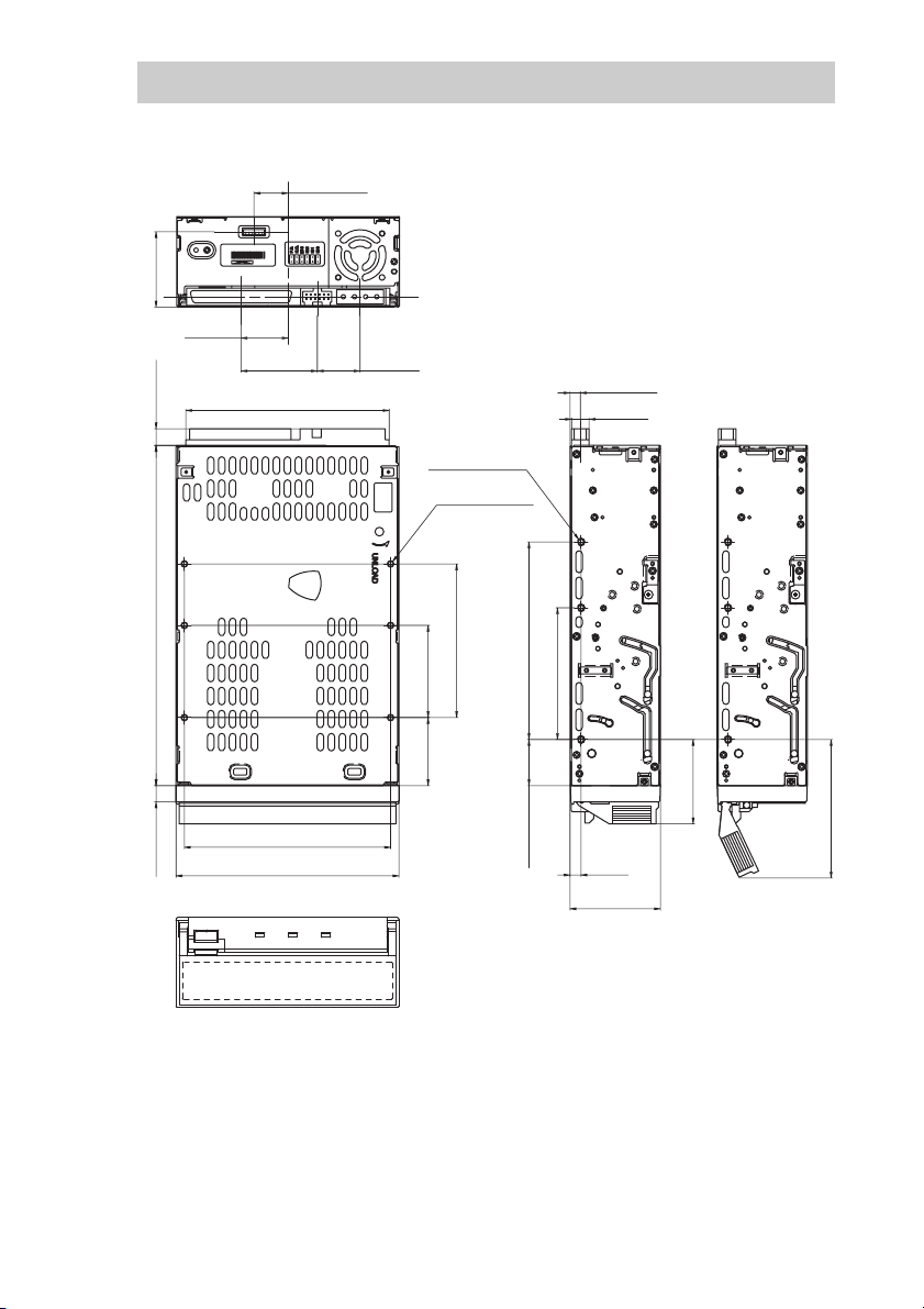
Mounting Holes
For 3.5" Standard Height (SDX-400C)
15.6 ±0.5 mm
[0.61"±0.02"]
SDX-400C
9911
[1.35"±0.02"]
34.3 ±0.5 mm
21.465 mm
[0.85"]
[0.3"±0.02"]
7.6 ±0.5 mm
[6.1" ±0.02"]
155 ±0.5 mm
34.75 mm
[1.37"]
92.71 mm
[3.65"]
19.48 mm
[0.77"]
6-M3 (depth 2.5mm [0.10"] max.)
6-M3 (depth 2.5mm [0.10"] max.)
70 ±0.3 mm
42 ±0.3 mm
[1.65" ±0.01"]
[2.76" ±0.01"]
90 ±0.3 mm
[3.54" ±0.01"]
60 ±0.3 mm
[2.36" ±0.01"]
4.7 ±0.5 mm
[0.19" ±0.02"]
8 mm
[0.31"]
7.4 ±0.5 mm
[0.29" ±0.02"]
94 ±0.3 mm
[3.7" ±0.01"]
101.6 ±0.5 mm
[4" ±0.02"]
31 ±0.3 mm
[1.22" ±0.01"]
21 ±0.3 mm
[0.83" ±0.01"]
5 ±0.3 mm
[0.2" ±0.01"]
41.2 ±0.5 mm
[1.62" ±0.02"]
[1.51"]
38.4 mm
[2.51"]
63.8 mm
9
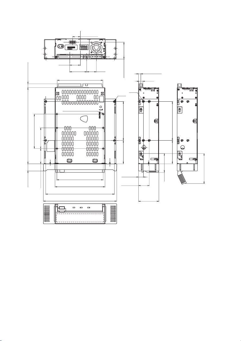
For 5.25" Half Height (SDX-400C/R)
15.6 ±0.5 mm
[0.61" ±0.02"]
SDX-400C/R
0101
21.465 mm
7.6 ±0.5 mm
[0.3" ±0.02"]
[6.1" ±0.02"]
155.0 ±0.5 mm
70.0 ±0.3 mm
[2.76" ±0.01"]
42.0 ±0.3 mm
[1.65" ±0.01"]
[0.85"]
34.75 mm
[1.37"]
92.71 mm
[3.65"]
6-M3(depth 2.5mm (0.10") max.)
19.48 mm
[0.77"]
34.3 ±0.5 mm
4-M3
0.3 mm
±
79.2
[1.35" ±0.02"]
[3.12" ±0.01"]
4-3M
4.7 ±0.5 mm
[0.19" ±0.02"]
8 mm
[0.31"]
P
P
P
P
P
79.2 ±0.3 mm
[3.12" ±0.01"]
P
P
P
[0.56" ±0.01"]
14.4 ±0.3 mm
31.0 ±0.3 mm
[1.22" ±0.01"]
94.0 ±0.3 mm
[3.7" ±0.01"]
101.6 ±0.5 mm
[4" ±0.02"]
139.6 ±0.5 mm
[5.5" ±0.02"]
149.0 ±0.5 mm
[5.87" ±0.02"]
47.5 ±0.3 mm
[1.87" ±0.01"]
9.9 ±0.5 mm
[0.39" ±0.02"]
21.8 ±0.5 mm
[0.86" ±0.02"]
41.2 ±0.5 mm
[1.62" ±0.02"]
[1.51"]
38.4 mm
47.5 ±0.3 mm
[1.87" ±0.01"]
±0.3 mm
[2.45" ±0.01"]
62.4
10
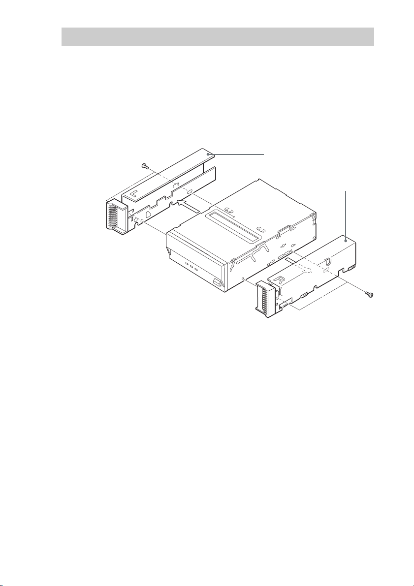
Remodeling from 5.25" Model to 3.5" Model
You can remodel the SDX-400C/R (5.25" model) to the SDX-400C (3.5"
model) yourself.
1 Remove the 2 screws for each side rail.
2 Take the side rail off.
Side Rail (L)
Side Rail (R)
11
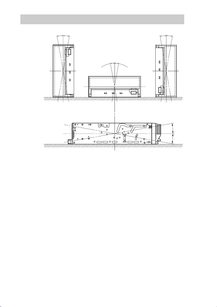
Orientation
10°
10° 10° 10°
10°
10°
10°
10°
12
Operation
Location of 3 LEDs
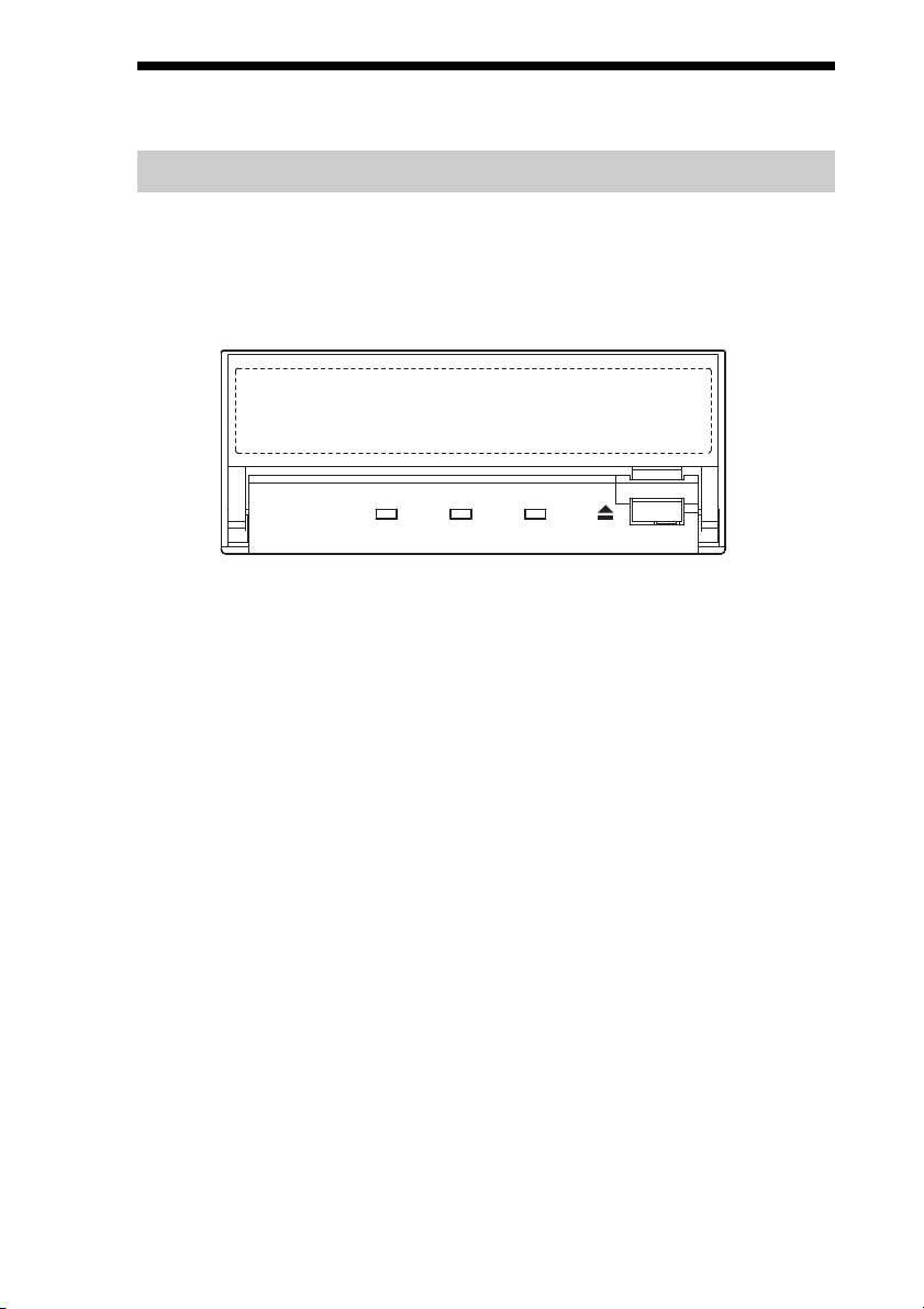
There are three LED indications (BUSY,TAPE and STATUS) and an
EJECT button on the front panel of the unit.
Front Panel (for 3.5" Standard Height)
Advanced
Intelligent
Tape
BUSY TAPE STATUS
BUSY TAPE S TATU S
13
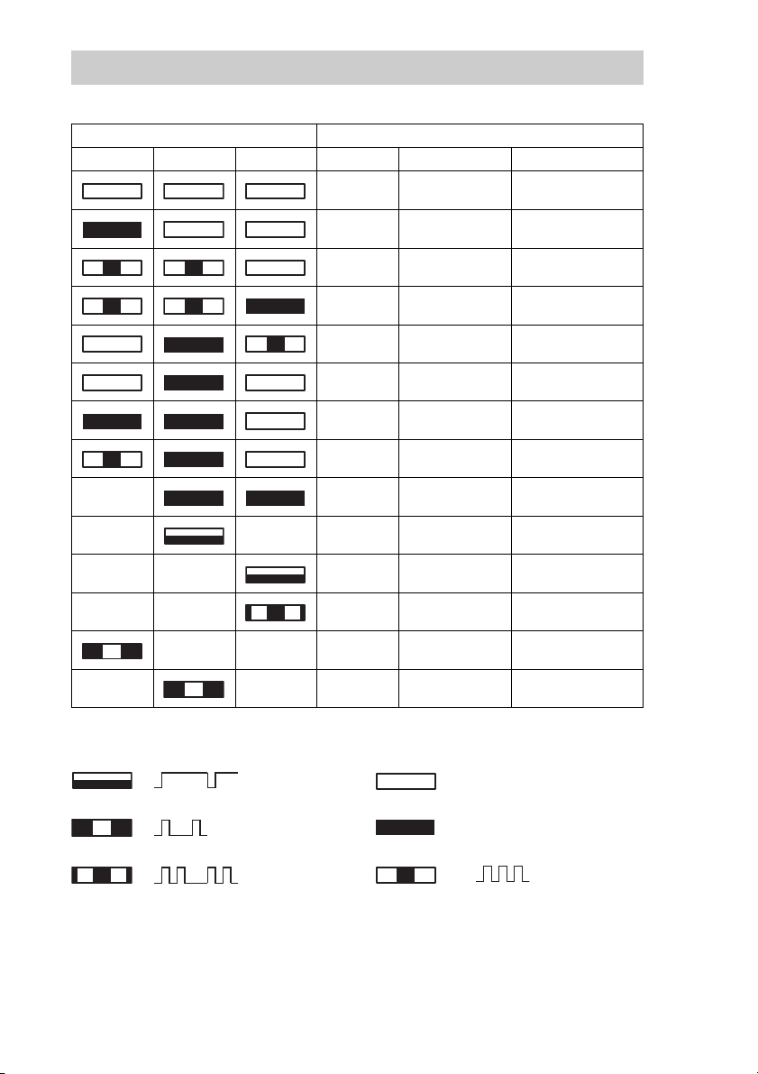
LED Indication for Drive Status
The LED indicators are defined as follows.
LED State
BUSY TAPE STATUS Activity Cartridge Other
None None None
SCSI None None
Drive
Drive
None Loaded
None Loaded None
SCSI Loaded None
SCSI/Drive Loaded None
Independent ✽ Loaded Write Protected
Independent Independent ✽ Loaded Error Rate Warning
✽✽ ✽✽Cleaning Request
✽✽ ✽✽Self test Failure
✽✽✽ ✽Waiting for Reset
✽ ✽✽ ✽Waiting for Eject
1 pulse (3.5 sec on / 0.5 sec off)
1 pulse (0.25 sec on)
Loading/Unloading
Loading/Unloading
off
on
None
Write Protected
Cleaning Tape at EOM
✽ : Not defined.
14
2 pulses (0.25 sec on/0.5 sec off)
1 pulse (0.25 sec on / 0.25 sec off)
 Loading...