

Page 1
SCSI/VGA COMBO CARDSCSI/VGA COMBO CARD
User’s Guide
Page 2

CopyrightCopyright
Copyright 1998 by this company. All rights reserved. No part of
this publication may be reproduced, transmitted, transcribed, stored in a
retrieval system, or translated into any language or computer language,
in any form or by any means, electronic, mechanical, magnetic, optical,
chemical, manual or otherwise, without the prior written permission of
this company.
DisclaimerDisclaimer
This company makes no representations or warranties, either
expressed or implied, with respect to the contents hereof and
specifically disclaims any warranties, merchantability or fitness for any
particular purpose. Any software described in this manual is sold or
licensed "as is". Should the programs prove defective following their
purchase, the buyer (and not this company, its distributor, or its dealer)
assumes the entire cost of all necessary servicing, repair, and any
incidental or consequential damages resulting from any defect in the
software. Further, this company reserves the right to revise this
publication and to make changes from time to time in the contents
hereof without obligation to notify any person of such revision or
changes.
Intel is a registered trademark of Intel Corporation.
Pentium II is a trademark of Intel Corporation.
PS/2 is a trademark of International Business Machines Corporation.
Other brand and product names are trademarks and/or registered trademarks of their
respective holders.
ii
Page 3

FCC Class B Radio FrequencyFCC Class B Radio Frequency
Interference StatementInterference Statement
Note:
This equipment has been tested and found to comply with the limits for
a Class B digital device, pursuant to Part 15 of FCC Rules. These
limits are designed to provide reasonable protection against harmful
interference in a residential installation. This equipment generates,
uses, and can radiate radio frequency energy and, if not installed and
used in accordance with the instructions, may cause harmful
interference to radio communications. However, there is no guarantee
that interference will not occur in a particular installation. If this
equipment does cause harmful interference to radio or television
reception, which can be determined by turning the equipment off and on,
the user is encouraged to try to correct the interference by one or more
of the following measures:
1. Reorient or relocate the receiving antenna.
2. Increase the separation between the equipment and receiver.
3. Connect the equipment into an outlet on a circuit different from that
to which the receiver is connected.
4. Consult the dealer or an experienced radio/television technician for
help.
Notice 1:
The changes or modifications not expressly approved by the party
responsible for compliance could void the user's authority to operate the
equipment.
Notice 2:
Shielded interface cables, if any, must be used in order to comply with
the emission limits.
iii
Page 4

Conventions
The following conventions are used in this manual:
Text entered by user Represents text input by the user.
, , , etc. Represent the actual keys that you
have to press on the keyboard.
NOTE
Gives bits and pieces of additional
information related to the current
topic.
CAUTION
Gives precautionary measures to
avoid possible hardware or software
problems.
iv
Page 5

Table of ContentsTable of Contents
Features...............................................................................1
Card Layout ..............................................................2
Jumper Settings ........................................................3
Card Installation.........................................................4
SCSI Feature ........................................................................5
Using the SCSI Feature..............................................5
Video Function......................................................................6
Supported Video Resolutions ......................................6
v
Page 6

SCSI/VGA Combo Card
Features
The combo card includes external video (CN6) and 68-pin Wide SCSI
interface (CN4).
The SCSI controller chipset (AIC-7880P) is a completely integrated,
single chip SCSI host adapter for motherboard applications. Ultra speed
SCSI technology maximizes transfer speed of up to 40MB/s in high
performance workstations and servers for greatest utilization of the 133
MB/s PCI local bus.
The ATI 3D Rage Pro VGA controller chipset is a highly integrated 64
bit graphics accelerator with support for 3D and motion video like
MPEG-2. It also incorporates comprehensive support for Intel's
Accelerated Graphics Port (AGP) including 66 or 133 MHz fully
pipelined operation with sidebands.
SCSI/VGA Combo Card 6
Page 7

Card Layout
Figure 1-1 shows the SCSI/VGA combo card layout and jumper
settings.
Figure 1-1 SCSI/VGA Combo Card Layout
SCSI/VGA Combo Card 7
Page 8

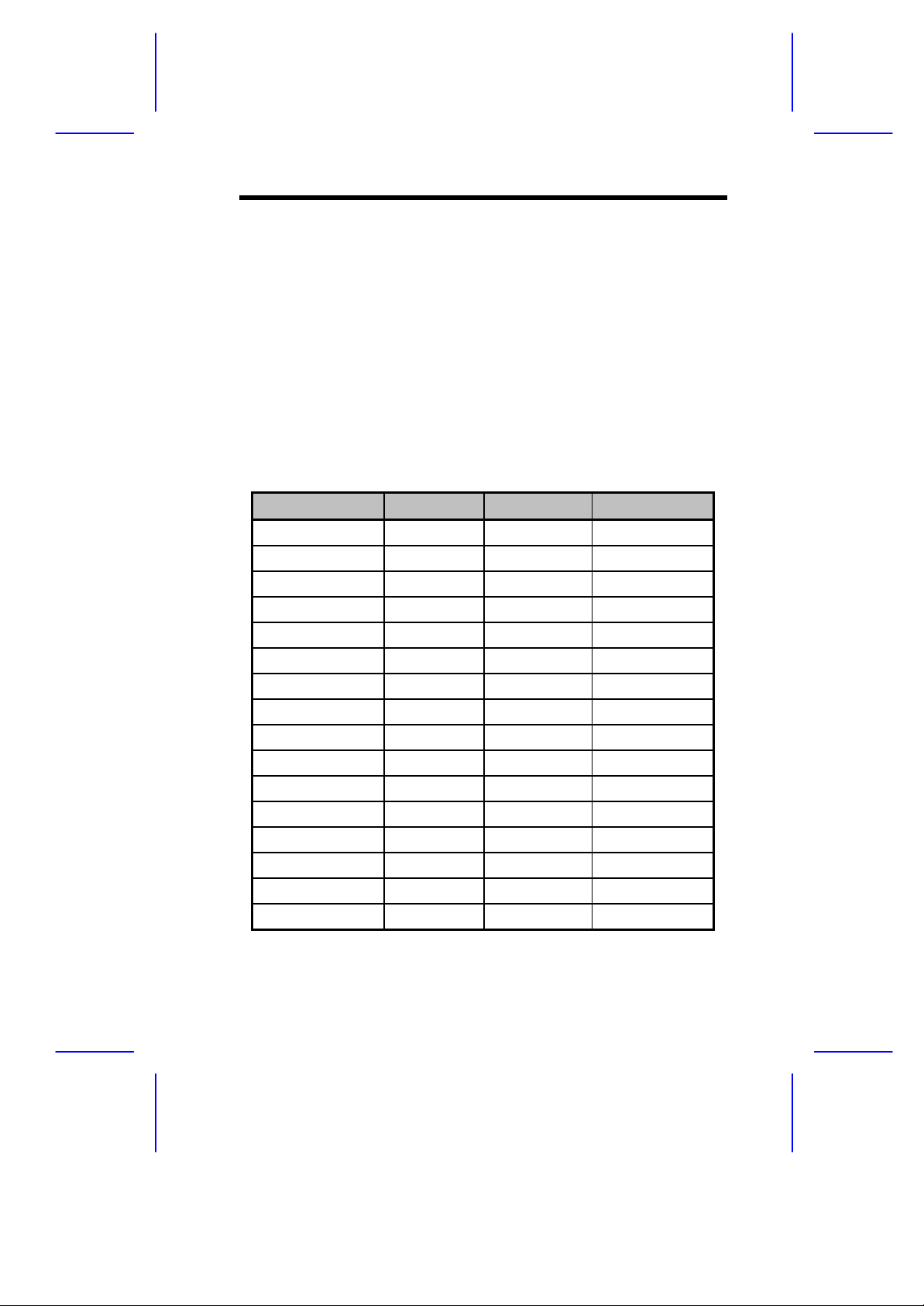
Jumper Settings
Table 1-1 SCSI/VGA Combo Card Jumper Settings
Jumper Setting Function
ROM Remapping
JP1 1-2
*
2-3
VGA Feature
JP2 1-2
2-3*
VGA Controller
JP3 1-2
2-3*
Interrupt
JP4 1-2
2-3*
Table 1-2 SCSI/VGA Combo Card Connector Functions
Connector Function
Map top 8K to bottom 8K
No remapping
Disabled
Enabled
Disabled
Enabled
Enabled
Disabled
CN1 68-pin Wide SCSI connector
CN2 50-pin Fast SCSI-II connector
CN3 ATI Multimedia connector
CN4 Ultra SCSI connector
CN5 LED connector
CN6 VGA connector
*
Default setting
8 User’s Guide
Page 9
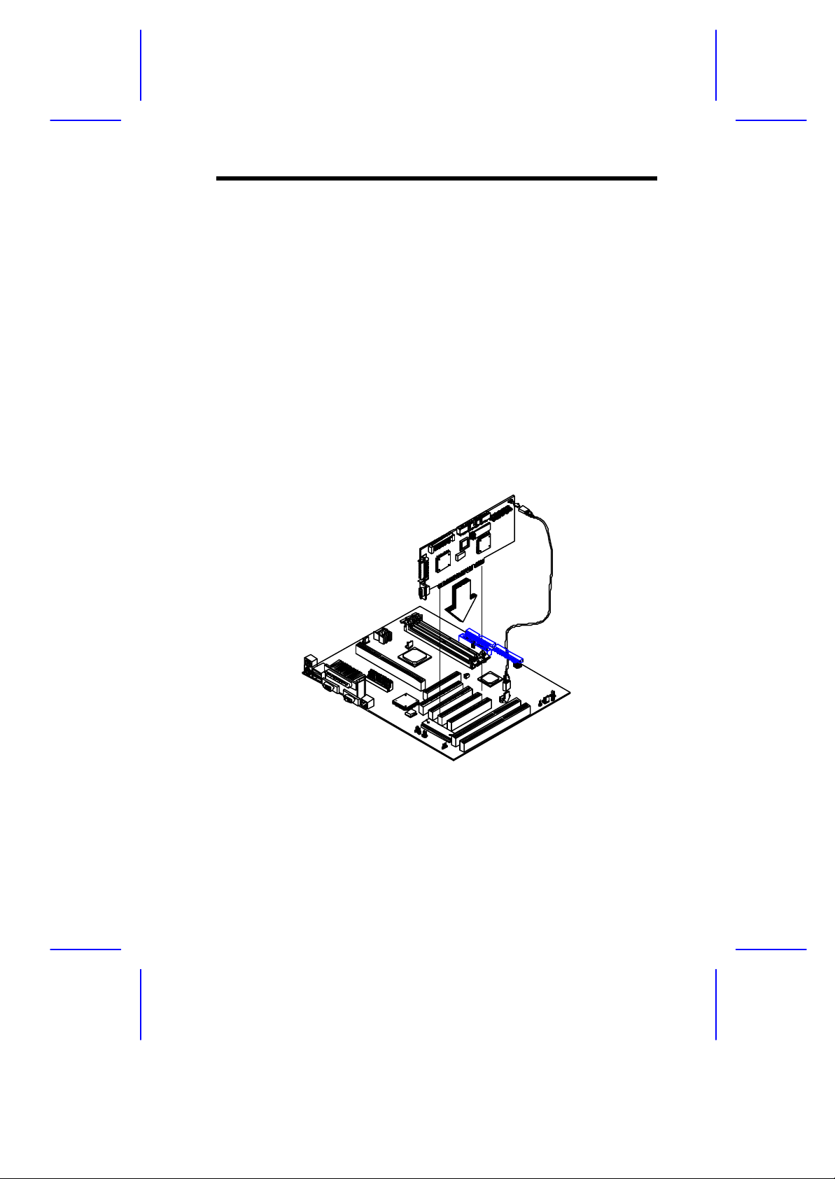
Card Installation
Follow these steps to install the SCSI/VGA combo card.
1. Remove a bracket cover opposite an empty PCI slot.
2. Position the card over the PCI slot, then insert the card golden
fingers into the slot until the card fits in place.
3. Secure the card with a screw.
4. Connect the LED cable to the system board’s SCSI LED connector
(please refer to the system board user’s manual for the location of
this connector) and then to the LED connector (CN5) on the combo
card.
Figure 1-2 Installing the SCSI/VGA Combo Card
SCSI/VGA Combo Card 9
Page 10

SCSI Feature
The system board features a single-chip SCSI host adapter that adds
SCSI I/O capability to the system. The chipset consists of an onboard
microcontroller, bus master interface controller, and SCSI controllers. A
50-pin Fast SCSI-II interface with 10 MB/s transfer rate and a 68-pin
Wide SCSI interface that transfers at 20 MB/s (Wide SCSI) and
40 MB/s (Ultra SCSI) are also onboard to accommodate various SCSI
devices.
Using the SCSI Feature
Follow these steps to use the SCSI feature:
1. Install a SCSI device in the system and connect it to the SCSI
interface on the system board. Please refer to the system board’s
user’s manual for the location of the SCSI interface.
2. Enter the BIOS utility to set the corresponding SCSI parameters.
3. Enter the SCSI Configuration Utility and make the necessary
changes.
For more information about the installation procedures under different
operating systems, read the README.XXX in the subdirectory of the
target operating system.
10 User’s Guide
Page 11
Video Function
The video controller is capable of supporting 3D video applications and
enhancing the video display at the same time. The board may come
with either 2-MB or 4-MB video memory. Larger video memory allows
you to display higher resolutions and more colors.
Supported Video Resolutions
The following table lists the video resolutions supported by the VGA
controller:
Table 1-3 Supported Video Resolutions
Resolution bpp V-Freg. (Hz) H-Freq. (KHz)
640 x 480 8/16/24/32 60 31.4
640 x 480 8/16/24/32 72 37.5
640 x 480 8/16/24/32 75 37.5
640 x 480 8/16/24/32 85 43.3
640 x 480 8/16/24/32 90 48.0
640 x 480 8/16/24/32 100 52.9
640 x 480 8/16/24/32 120 63.7
640 x 480 8/16/24/32 160 84.1
800 x 600 8/16/24/32 48 33.8
800 x 600 8/16/24/32 56 35.2
800 x 600 8/16/24/32 60 37.8
800 x 600 8/16/24/32 70 44.5
800 x 600 8/16/24/32 72 48.0
800 x 600 8/16/24/32 75 46.9
800 x 600 8/16/24/32 85 53.7
800 x 600 8/16/24/32 90 57.1
SCSI/VGA Combo Card 11
Page 12
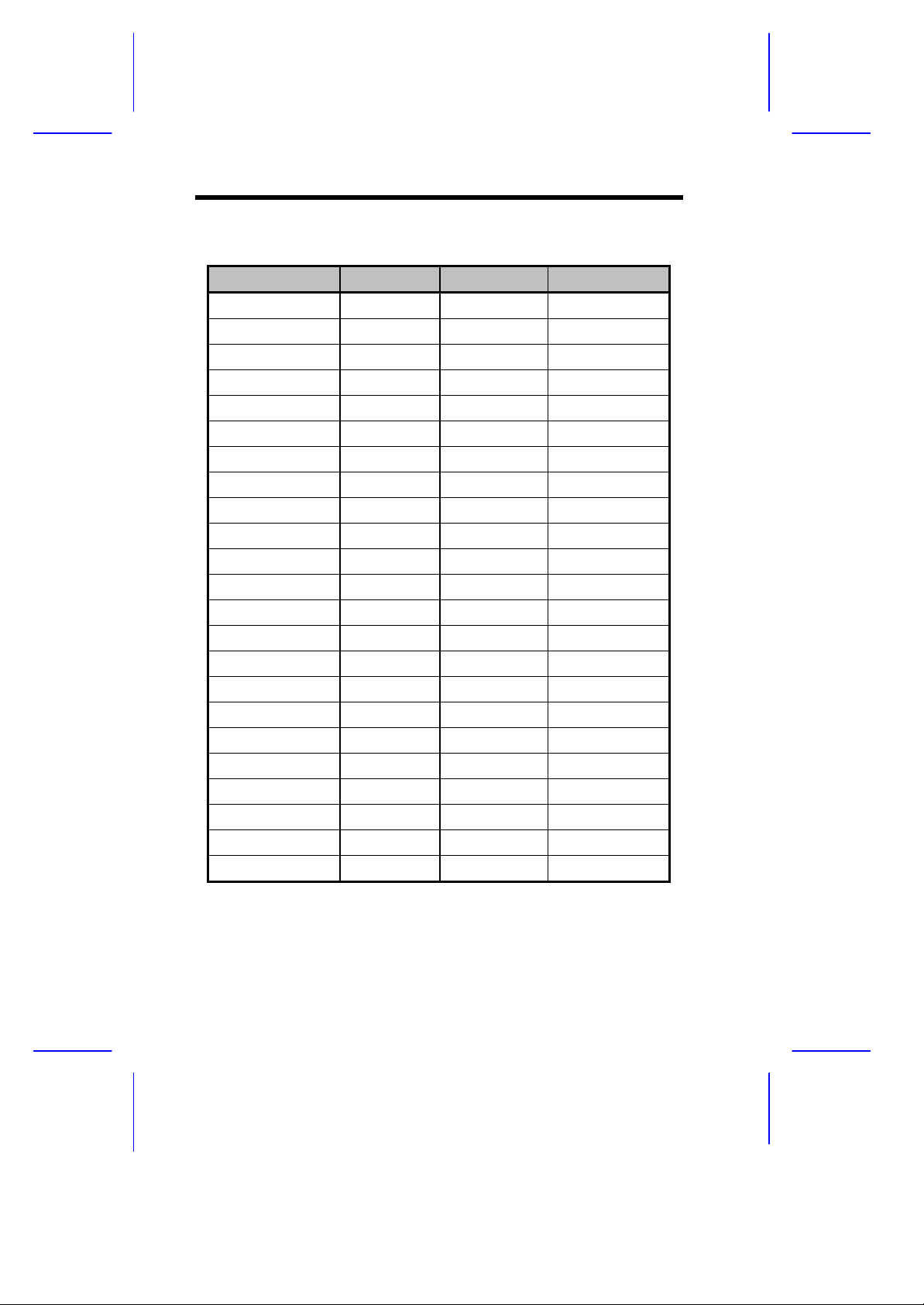
Table 1-3 Supported Video Resolutions
Resolution bpp V-Freg. (Hz) H-Freq. (KHz)
800 x 600 8/16/24/32 100 62.5
800 x 600 8/16/24/32 120 76.0
800 x 600 8/16/24 160 99.6
1024 x 768 8/16/24/32 43 35.5
1024 x 768 8/16/24/32 60 48.4
1024 x 768 8/16/24/32 70 56.5
1024 x 768 8/16/24/32 72 58.2
1024 x 768 8/16/24/32 75 60.0
1024 x 768 8/16/24/32 85 68.7
1024 x 768 8/16/24/32 90 76.2
1024 x 768 8/16/24/32 100 79.0
1024 x 768 8/16/24 120 96.7
1152 x 864 8/16/24/32 43 45.9
1152 x 864 8/16/24/32 47 44.9
1152 x 864 8/16/24/32 60 54.9
1152 x 864 8/16/24/32 70 66.1
1152 x 864 8/16/24/32 75 75.1
1152 x 864 8/16/24/32 80 76.4
1152 x 864 8/16/24 85 77.1
1152 x 864 8/16 100 90.2
1280 x 1024 8/16/24 43 50
1280 x 1024 8/16/24 47 50
1280 x 1024 8/16/24 60 64.0
12 User’s Guide
 Loading...