

Acer AAS700, S700, S700F User Manual

Altos S700 Series
User’s Guide

Copyright © 2002 Acer Incorporated
All Rights Reserved.
Altos S700 Series
User’s Guide
Changes may be made periodically to the information in this publication without obligation
to notify any person of such revision or changes. Such changes will be incorporated in new
editions of this manual or supplementary documents and publications. This company makes
no representations or warranties, either expressed or implied, with respect to the contents
hereof and specifically disclaims the implied warranties of merchantability or fitness for a
particular purpose.
Record the model number, serial number, purchase date, and place of purchase information in
the space provided below. The serial number and model number are recorded on the label
affixed to your computer. All correspondense concerning your unit should include the serial
number, model number, and purchase information.
No part of this publication may be reproduced, stored in a retrieval system, or transmitted, in
any form or by any means, electronic, mechanical, photocopy, recording, or otherwise,
without the prior written permission of Acer Incorporated.
Model Number : _________________________________
Serial Number: ___________________________________
Purchase Date: ___________________________________
Place of Purchase: ________________________________
Acer and the Acer logo are registered trademarks of Acer Inc. Other company’s product
names or trademarks are used herein for identification purposes only and belong to their
respective companies.

Preface vii
Audience vii
Conventions Used In This User Guide vii
European Community Statement xv
Introduction 3
Features 4
Disk Drive Carrier 4
Power Supplies 4
Cooling System 5
I/O Option Modules 6
Safety Statements 13
Unpacking and Initial Setup 15
Installing the System in an Equipment Rack 16
Ambient Temperature 16
Air Flow 16
Mechanical Loading 16
Electrical Considerations 18
Circuit Overloading 18
Setting Fibre Channel Loop Speed (2Gb or 1Gb) 19
2Gb Operation 19
1Gb Operation 19
Split Fibre Channel Loop Operation (Quad Loop) 21
Setting Up Split Loop Operation 21
Removing Split Loop Operation 21
Configuration Rules 23
Supported Host Bus Adapters 24
Supported Cables 25
Copper Cables 25
Optical Cables 26
Setting the Enclosure ID 29
Configurations 32
JBOD Configurations 33
Dual FC Loop Configuration 33
Quad Loop Configuration 35
Connecting a Power Source 37
Connecting an AC Power Source 37
Disk Drive Spin Up Sequence 38
Altos S700 Series RAID Controller Introduction 41
RAID Controller Circuit Boards 43
Controller Circuit Board 43
I/O Circuit Board 43
RS232 Serial Port 44
RAID Controller Location 45
Contents

RAID Controller Status LEDs 46
RAID Controller Configurations 47
Setting the Enclosure ID 48
Configurations 51
Single RAID Controller Configuration 51
Dual RAID Controller Configuration 54
Connecting a Power Source 57
Connecting an AC Power Source 57
Disk Drive Spin Up Sequence 58
Overview 61
LS Module 62
LS Module Features 62
Altos S700 Enclosure LEDs 63
Disk Drive LEDs 65
Power Supply LEDs 67
Advanced Cooling Module (ACM) LEDs 68
RAID Controller LEDs 69
Location of the Components 73
Installing and Removing a Disk Drive Carrier 74
Installing a Disk Drive Carrier 74
Removing a Disk Drive Carrier 74
Installing and Removing an LS Module 76
Installing an LS Module 76
Removing an LS Module 76
Installing and Removing a Power Supply 78
Installing a Power Supply 78
Removing a Power Supply 78
Installing and Removing an Advanced Cooling Module 79
Installing an Advanced Cooling Module 79
Removing an Advanced Cooling Module 79
Installing and Removing an I/O Module/RAID Controller 80
Installing an I/O Module/RAID Controller 80
Removing an I/O Module/RAID Controller 80
Caution: 82
Warning 88
Technical Specifications 90
Host Interface 90
Disk Drive Interface 90
System 90
Redundant, Hot Swappable Components 90
Physical Dimensions 90
Warranty 91
Monitoring 91
Failure Notification 91
Contentsiv

Disk Drives 92
Power Supply 92
Temperature 92
Humidity 92
Altitude 92
Operational Shock 93
Operational Vibration 93
Regulatory Agency Compliance 93
Equipment and parts necessary for upgrade 103
Upgrading from JBOD to RAID 103
Installing the Battery Backup Unit 104
v

Contentsvi
vii
Preface
This Installation Guide describes the installation and operation of the
Altos S700 Series. The following products are covered: AS.S7001.001,
AS.S7001.002, AS.S7001.003, AS.S7001.004, AS.S7001.005,
AS.S7001.006.
Audience
This Installation Guide is intended for use by the person installing and
operating the Altos S700 Series. This Installation Guide describes the
operation of the Altos S700 Series only. For details relating to the host
system, refer to the documentation supplied with the host system.
Conventions Used In This User Guide
The following conventions are used throughout this Installation Guide.
A NOTE gives general information, such as helpful tips and
references to related information.
A CAUTION means take care. There is a risk of causing damage to
the equipment or losing data.
A WARNING means beware. There is a risk of electric shock
or personal injury. Before working on the enclosure be
aware of the hazards that exist.

viii
Notices
FCC notice
This device has been tested and found to comply with the limits for a Class B
digital device pursuant to Part 15 of the FCC Rules. These limits are designed to
provide reasonable protection against harmful interference in a residential
installation. This device generates, uses, and can radiate radio frequency
energy, and if not installed and used in accordance with the instructions, may
cause harmful interference to radio communications.
However, there is no guarantee that interference will not occur in a particular
installation. If this device does cause harmful interference to radio or television
reception, which can be determined by turning the device off and on, the user
is encouraged to try to correct the interference by one or more of the following
measures:
• Reorient or relocate the receiving antenna
• Increase the separation between the device and receiver
• Connect the device into an outlet on a circuit different from that to which
the receiver is connected
• Consult the dealer or an experienced radio/television technician for help
Notice: Shield cables
All connections to other computing devices must be made using shielded cables
to maintain compliance with FCC regulations.
Notice: Peripheral devices
Only peripherals (input/output devices, terminals, printers, etc.) certified to
comply with the Class B limits may be attached to this equipment. Operation
with noncertified peripherals is likely to result in interference to radio and TV
reception.
Caution! Changes or modifications not expressly approved by
the manufacturer could void the user’s authority, which is granted
by the Federal Communications Commission, to operate this
computer.

Use conditions
This part complies with Part 15 of the FCC Rules. Operation is subject to the
following two conditions: (1) this device may not cause harmful interference,
and (2) this device must accept any interference received, including interference
that may cause undesired operation.
Notice: Canadian users
This Class B digital apparatus meets all requirements of the Canadian
Interference-Causing Equipment Regulations.
Remarque à l’intention des utilisateurs canadiens
Cet appareil numérique de la classe B respected toutes les exigences du
Règlement sur le matériel brouilleur du Canada
.
ix

x
Important safety information
Only a technically qualified person shall access, integrate, configure, and service
this product.
Intended application uses
This product was evaluated as Information Technology Equipment (ITE), which
may be installed in offices, schools, computer rooms, and similar commercial
type locations. The suitability of this product for other Product Categories and
Environments (such as medical, industrial, alarm systems, and test equipment),
other than an ITE application, may require further evaluation.
Checking the power cords
Warning! To avoid electrical shock, do not attempt to
modify or use the supplied AC power cord(s), if they are
not the exact type required.
If a power cord(s) supplied is not compatible with the AC wall outlet in your
region, get one that meets the following criteria:
• The power cord must be properly rated for the AC voltage in your region.
• The power cord plug cap must have an electrical current rating that is at
least 125% of the electrical current rating of the product.
• The power cord plug cap that plugs into the wall socket-outlet must have a
grounding-type male plug designed for use in your region.
• The power cord must have safety certifications for your region, and shall
be marked with the certification markings.
• The power cord plug cap that plugs into the AC receptacle on the power
supply must be an IEC 320, sheet C13, type female connector.
• In Europe, the power cord must be less than 4.5 meters (14.76 feet) long,
and it must be flexible <HAR> (harmonized) or VDE certified cordage to
comply with the chassis' safety certifications.
• The power supply cord(s) is the main disconnect device to AC power. The
socket outlet(s) shall be near the equipment and shall be readily accessible
for disconnection.

Multiple power cords
Warning! To avoid electrical shock, disconnect all AC power cords before
accessing inside the system.
Earth grounded socket-outlets
Warning! To avoid electrical shock, the system power cord(s) must be plugged
into socket-outlet(s) that is provided with a suitable earth ground.
Precautionary reminders
• Over current protection
The system is designed to operate on a 20A AC voltage source that is
provided with 20A over current protection. If the AC source for the rack
exceeds 20A over current protection, each system must be provided with
20A or less over current supplemental protection. The supplementary over
current protection must have the appropriate regional safety certifications
for the over current application.
• Power supply modules
Power supply modules have double-pole/neutral fusing.
• Ventilation considerations
The equipment rack must provide sufficient airflow to the front of the
system to maintain proper cooling. The rack selected and the ventilation
provided must be suitable to the environment in which the system will be
used.
•Fans
To avoid injury do not touch moving fan blades.
• Cooling and airflow
For proper cooling and airflow, always install all access covers before
turning on the system. Operating the system for longer than five minutes
without the covers in place can cause overheating and damage to system
components.
• Temperature limits
• The operating temperature of the system, when installed in the rack, must
not go below 10 °C (50 °F) or rise above 35 °C (95 °F). Extreme fluctuations
in temperature may cause a variety of problems in system, and safety limits
may be broken.
• Lifting and Moving
Do not attempt to lift or move the server by the handles on the power
supplies.
xi

xii
Equipment rack precautions
Follow the rack manufacturer's safety and installation instructions for proper
rack installation.
The following additional rack safety installation measures shall be considered:
• Anchor the equipment rack
The equipment rack must be anchored to an unmovable suitable support
to prevent the rack from falling over when one or more systems are fully
extended out of the rack assembly. You must also consider the weight of
any other devices installed in the rack assembly. The equipment rack must
be installed according to the manufacturer's instructions.
• Main AC power disconnect
You are responsible for installing an AC power disconnect for the entire
rack unit. This main disconnect must be readily accessible, and it must be
labeled as controlling power to the entire unit, not just to the system(s).
• Grounding the rack installation
To avoid the potential for an electrical shock hazard, the rack assembly
itself must be suitably earth grounded, according to your local regional
electrical codes. This typically will require the rack to have its own separate
earth ground. We recommend you consult your local approved electrician.

xiii
Important safety instructions
Read these instructions carefully. Save these instructions for future reference.
1 Follow all warnings and instructions marked on the product.
2 Unplug this product from the wall outlet before cleaning. Do not use
liquid cleaners or aerosol cleaners. Use a damp cloth for cleaning.
3 Do not use this product near water.
4 Do not place this product on an unstable cart, stand, or table. The product
may fall, causing serious damage to the product.
5 Slots and openings in the cabinet and the back or bottom are provided for
ventilation; to ensure reliable operation of the product and to protect it
from overheating, these openings must not be blocked or covered. The
openings should never be blocked by placing the product on a bed, sofa,
rug, or other similar surface. This product should never be placed near or
over a radiator or heat register, or in a built-in installation unless proper
ventilation is provided.
6 This product should be operated from the type of power indicated on the
marking label. If you are not sure of the type of power available, consult
your dealer or local power company.
7 Do not allow anything to rest on the power cord. Do not locate this
product where persons will walk on the cord.
8 If an extension cord is used with this product, make sure that the total
ampere rating of the equipment plugged into the extension cord does not
exceed the extension cord ampere rating. Also, make sure that the total
rating of all products plugged into the wall outlet does not exceed the fuse
rating.
9 Never push objects of any kind into this product through cabinet slots as
they may touch dangerous voltage points or short out parts that could
result in a fire or electric shock. Never spill liquid of any kind on the
product.
10 Do not attempt to service this product yourself, as opening or removing
covers may expose you to dangerous voltage points or other risks. Refer all
servicing to qualified service personnel.
11 Unplug this product from the wall outlet and refer servicing to qualified
service personnel under the following conditions:
a When the power cord or plug is damaged or frayed
b If liquid has been spilled into the product
c If the product has been exposed to rain or water

xiv
d If the product does not operate normally when the operating
instructions are followed. Adjust only those controls that are covered
by the operating instructions since improper adjustment of other
controls may result in damage and will often require extensive work
by a qualified technician to restore the product to normal condition.
e If the product has been dropped or the cabinet has been damaged
f If the product exhibits a distinct change in performance, indicating a
need for service.
12 Replace the battery with the same type as the product's battery we
recommend. Use of another battery may present a risk of fire or explosion.
Refer battery replacement to a qualified serviceman.
13 Warning! Batteries may explode if not handled properly. Do not
disassemble or dispose of them in fire. Keep them away from children and
dispose of used batteries promptly. Dispose of used batteries according to
manufacturer's instructions.
14 Use only the proper type of power supply cord set (provided in your
accessories box) for this unit. It should be a detachable type: UL listed/CSA
certified, type SPT-2, rated 7A 125V minimum, VDE approved or its
equivalent. Maximum length is 15 feet (4.6 meters).

European Community Statement
This equipment complies with the following European directives:
EMC Directive 89/336/EEC and amending Directives 92/31/EEC and 93/
68/EEC Low Voltage Directive 73/23/EEC.
xv

xvi

Chapter 1
Introduction

This Chapter introduces the Altos S700 Series. The main
features of the Series are described along with a list of the
models that are available.

Introduction
The Altos S700 Series provides a highly flexible, high performance
storage solution that evolves to meet your changing needs. Based on a
modular, “building block” enclosure design, the Altos S700 Series
offers exceptional scalability. Each enclosure supports up to 14 disk
drives, in a dense 3U form factor. As your storage needs grow, simply
add Altos S700 enclosures dynamically - up to a total of 8 enclosures.
The Altos S700 Series can be scaled in multiple dimensions, enabling
flexible configuration of capacity, performance and functionality, to
match and grow with virtually any application or IT environment. The
enclosure is available with your choice of copper, or optical I/O
modules, with RAID Controller option, and is downward compatible to
1Gbps, protecting your investment. A high performance, industry first
Quad Loop
700 MB/s from a single enclosure. 2Gb Fibre Channel connectivity
provides simplified cabling and extremely high bandwidth, for
outstanding performance in demanding applications.
1
(4 FCAL loops on one enclosure) capability provides over
1
Quad Loop functionality is only available on JBOD systems.
3

Chapter 1 Introduction4
Features
• Redundant data paths with dual-ported fibre drives and dual
(200MB/s) fibre channel loops for a total of 400 MB/s.
• Quad Loop feature, provides over 700MB/s from a single enclosure.
• RAID controller option to give RAID functionality.
• Downward compatible to 1Gbps.
• Dense enclosure with 14 drives in a 3U form factor.
• Scalable to 112 drives, support for 15K rpm drives.
• Enhanced enclosure services (SES) monitoring and reporting.
• No single point of failure, with redundant, hot-swappable
components.
• Intuitive, comprehensive management with Spheras Storage
Manager.
• User installable, configurable and on-line maintainable.
• Industry-standard 19-inch rackmount or deskside configuration.
• Dual AC power supplies.
Disk Drive Carrier
The disk drive carrier supports one inch, SCA-2 direct attach disk drives.
The Altos S700 Series can hold up to fourteen disk drive carriers. The
disk drives can be hot swapped and the disk drive carriers provide for
blind mating.
Power Supplies
The Altos S700 Series uses two AC power supplies for normal
operation, providing redundancy of the power system. The power
supplies can be hot swapped. The AC power supplies provide 673 Watts
continuous output power and 853 Watts peak output power. The
power supplies provide active current sharing, power factor correction,
over current and over voltage protection is also provided. The power
supplies have individual power inputs.
5
Caution: Power supply cords shall have conductors with a crosssectional area not less than 4mm
corresponds to a minimum 10AWG wire.
2
. This cross-sectional area
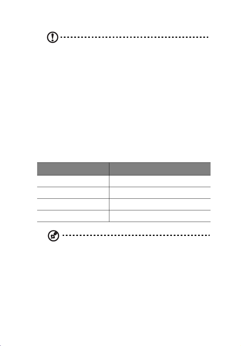
Cooling System
Cooling is provided by the two Advanced Cooling Modules (ACMs)
located at the rear of the enclosure. Each of the ACM units contain two
variable speed fans. The enclosure requires four fans for normal
operation, but will operate correctly with one fan failed (redundancy is
lost if one fan is failed in either ACM), however, it is recommended
that the failed fan be replaced as soon as possible. The ACM units can
be hot swapped. The LS Module monitors and controls the speed of
each fan. The speed is set depending on the ambient temperature and
failed status. The fans are set to full speed if one fan is failed. The
following table shows how the fan speed relates to temperature
change.
ACM Speed
Speed 1 0 to 26
Speed 2 26 to 28
Speed 3 28 to 30
Ambient Temp (oC)
Full Speed 30 +
Note: All fans in an enclosure are set to the same speed.
Chapter 1 Introduction6
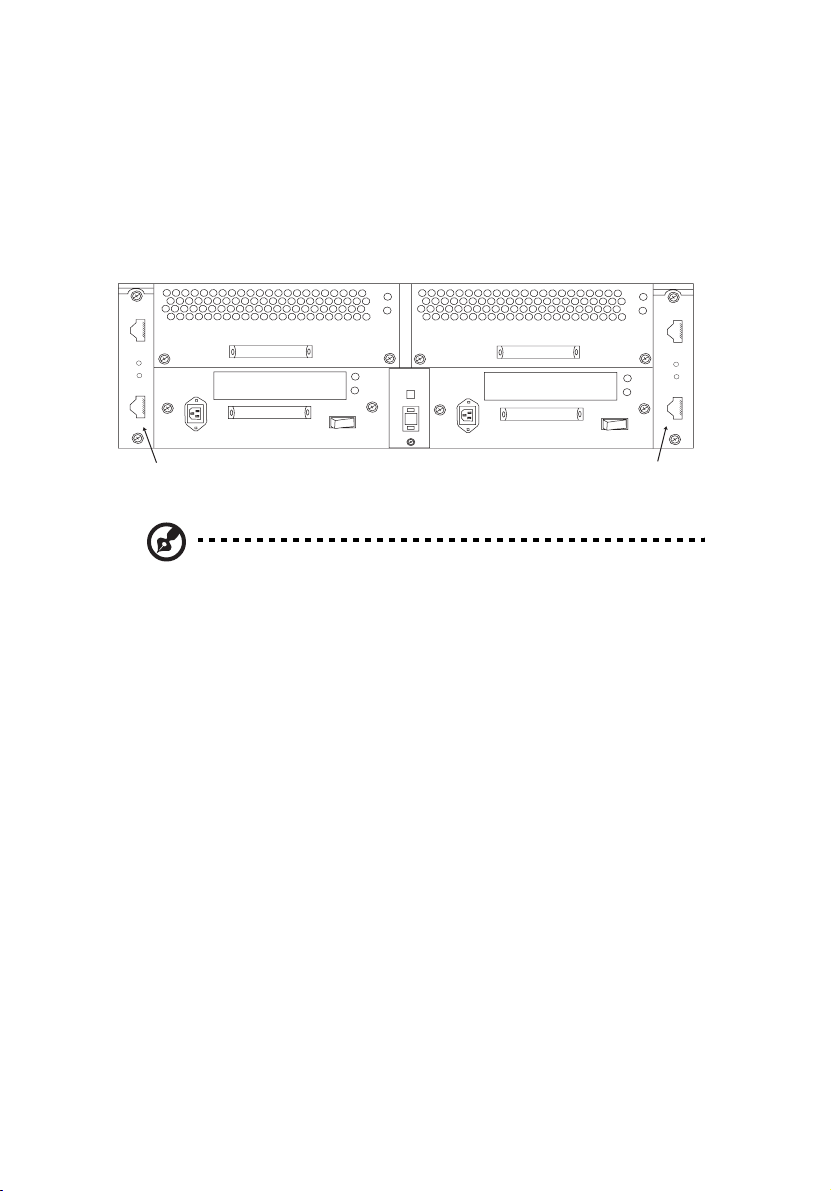
I/O Option Modules
The two rear I/O option slots (A and B) can contain a range of different
option modules. The LS module will detect the type of option module
installed.
I/O Option
Slot B
1
2
0
I
0
I
1
2
I/O Option
Slot A
Note: The above illustration shows the copper/copper I/O option
modules.
The available option modules are:
I/O Expansion Module - Copper/Copper
This 2Gb FC expansion module has two HSSDC connectors. The top
connector is the primary FC loop input port and the bottom connector
is available for FC loop expansion / input. A fibre channel loop back
terminator is not required.
I/O Expansion Module - Optical/Copper
This 2Gb FC expansion module has the SFF LC optical connector as the
FC Loop Input port. The FC loop expansion is carried out by the HSSDC
connector. A loop back terminator is not required.

I/O Expansion Module- Optical/Optical
This 2Gb FC expansion module has two SFF LC optical connectors. The
top connector is the FC Loop Input port and the bottom connector is
for FC Loop Expansion. A loop back terminator is not required.
Altos S700 RAID Controller
The Altos S700 RAID Controller is a high performance controller,
providing two host fibre channel
interfaces. It is an intelligent, caching controller that supports
RAID levels 0, 1, 3, 5, 0+1, and JBOD. The controller enables
multiple hosts to access an array of disk drives, which can be
configured as one or more virtual storage devices (logical units).
and two device fibre channel
7
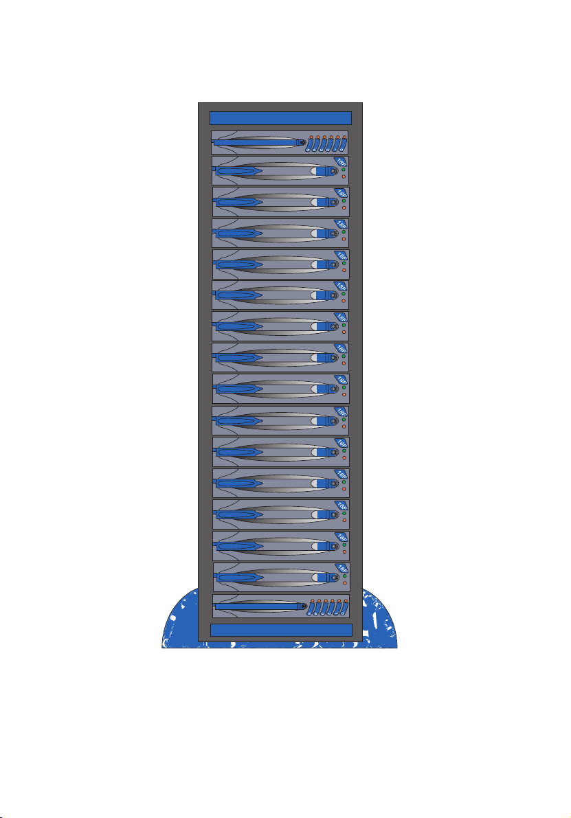
Figure 1-1: Altos S700 Series Tower Model
Chapter 1 Introduction8
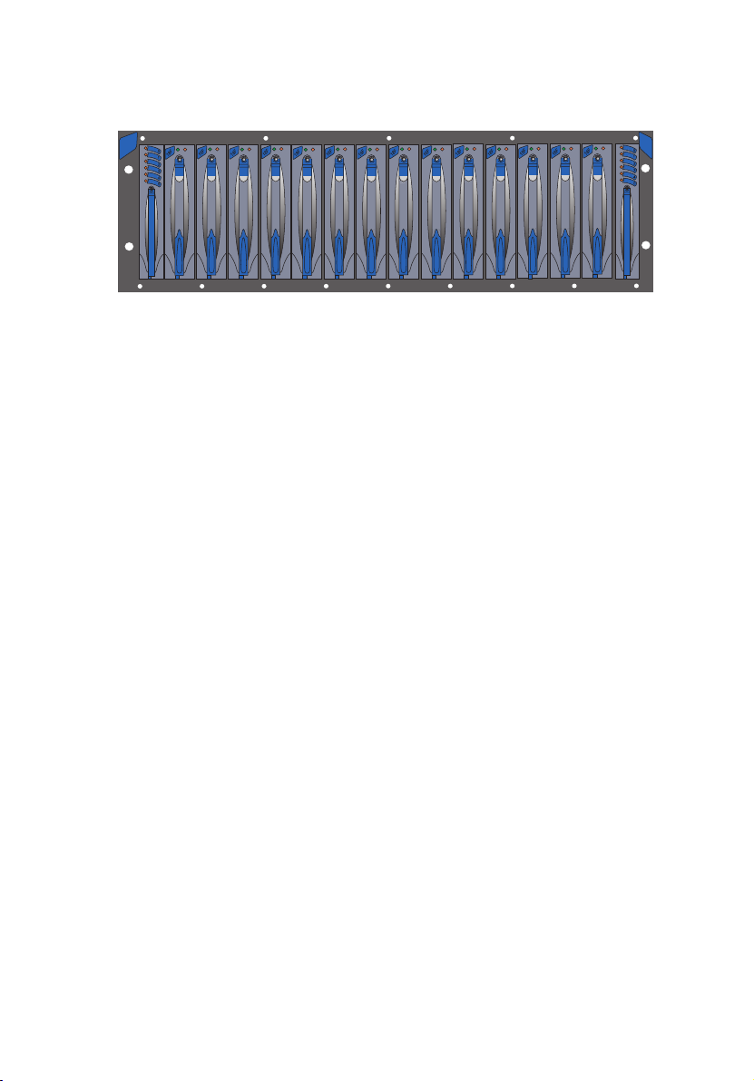
Figure 1-2: Altos S700 Series Rack Model
9

Chapter 1 Introduction10

Chapter 2
Installation and Setup

This Chapter describes the installation and set up of the Altos S700 Series.
Important safety instructions are discussed along with the electrical,
mechanical and environmental precautions that need to be taken. Items
that need to be set prior to operating the Altos S700 enclosure are also
described here.
Note: Please read this Chapter carefully before attempting to install
or operate the Altos S700 Series enclosure.
Safety Statements
The following safety statements must be read before you install or
operate the Altos S700 Series. For language translations of these
statements refer to Appendix B.
Caution: This equipment is intended only for installation in a
restricted access location.
Caution: Before attempting to install or remove any of the
components, ensure that anti-static precautions are taken. The
minimum requirement is, a properly grounded anti-static wrist
strap and ground wire.
Caution: If any of the components are removed the resulting hole
must be blocked, by installing a component blank or replacing the
component. Failure to do so can seriously restrict air flow and
cooling.
13
Caution: This device should be connected to a power source
which carries a fuse or circuit breaker that is greater than the
rating of the shelf, but also complies with national wiring
standards.
Caution: Allow disk drives and power supplies to reach room
ambient temperature before powering on the shelf.
Caution: It is recommended that, if interconnecting equipment
resides within more than one equipment rack cabinets, these
equipment racks should be at the same ground potential.

Chapter 2 Installation and Setup14
Warning: A possible shock hazard may exist in the area of
the fan connection.
Warning: Disconnect the power cords before removing a
power supply from the enclosure.
 Loading...