

Page 1

RESTRICTIONS ON USE OF MATERIALS
:
Projector Service Manual
Model: S5201/S5201B/S5301WB series
Version: Rev1
First Edition (Dec. 2010)
1
Page 2

Index
REVISION LIST ....................................................................................................................3
CHAPTER 1 SYSTEM SPECIFICATION .........................................................................4
Product Specification ..................................................................................................................4
Electrical Specification...........................................................................................12
Power Supply Specification ...................................................................................20
System Block Diagram ............................................................................................................. 21
Product Overview ......................................................................................................................22
CHAPTER 2 SYSTEM UTILITIES..................................................................................26
Firmware Upgrade SOP...........................................................................................................26
Method to enter factory menu .................................................................................................35
EDID Upgrade SOP ..................................................................................................................36
Serial Number Upgrade SOP ..................................................................................................39
CHAPTER 3 SYSTEM DISASSEMBLING AND REPLACEMENT ................................41
Main Unit Disassembling.......................................................................................................... 41
Module Assembly Key Point - Optical Engine ...................................................................... 46
Module Assembly Key Point – Mechanical ........................................................................... 57
CHAPTER 4 TROUBLESHOOTING ..............................................................................75
System Analysis ........................................................................................................................ 75
Optical & Optical Engine Trouble Shooting Guide ............................................................... 76
Power Supply Trouble Shooting Guide.................................................................................. 81
LED Messages Definition.........................................................................................................84
Error Count Messages Definition............................................................................................ 85
RS232 Connection ....................................................................................................................86
Adjustment / Alignment Procedure......................................................................................... 87
CHAPTER 5 FRU LIST ..................................................................................................90
Exploded Diagram.....................................................................................................................90
Module 1 – Total Exploded View............................................................................................. 90
Module 2 – ASSY UPPER CASE ........................................................................................... 92
Module 3 – ASSY LOWER CASE .......................................................................................... 93
Module 4 – ASSY FRONT CASE ...........................................................................................94
Module 5 – ASSY REAR CASE.............................................................................................. 95
FRU List ......................................................................................................................................96
FRU List ......................................................................................................................................96
APPENDIX A - CODE LIST: IR / RS232 / DDC DATA......................................................101
1. Remonte control code ........................................................................................................101
2. RS-232 Command Code ...................................................................................................102
3. DDC Data.............................................................................................................................104
2
Page 3

Revision List
Version
Rev0 2010.12.21 First Release
Rev1 2011.01.11
Release
Date
Revision History
Add S5201B/S5301WB
(1) Ch1-Add SPEC
(2) Ch2-Update Firmware Upgrade SOP
(3) Ch3-Disassembly process, Module Assembly Key Point
(4) Ch4-Add “DMD Image Quality “ section,
Change RS232 baud rate default to 9600.
(5) Ch5-FRU List
(6) App.-DDC data
Vendor
Model
Name
3
Page 4

Chapter 1 System Specification
Product Specification
1.0 Optical Performance
2.0 Image Quality
3.0 Mechanical Specification
4.0 Packaging
5.0 Thermal Specification
6.0 Environmental
7.0 Regulatory
8.0 Reliability
9.0 Power Requirements
10.0 Panel Specification
11.0 Compatibility
12.0 Image Interface
13.0 Control Interface
14.0 User Interface
4
Page 5
1.0 Optical Performance
Tested under 60” (diagonal) image size with Wide
projection lens position unless other specified.
1.1 ANSI Brightness Minimum 2400 Lumens
1.2 Brightness Uniformity
1.2.1 ANSI Uniformity Minimum 45%
1.2.2 JBMA Uniformity Minimum 65%
1.2.3 Upper-Down
unbalance
0.5~2
1.2.4 Left-Right unbalance 0.6~1.67
1.3 Contrast Ratio
1.3.1 ANSI Contrast Minimum 150:1
1.3.2 FOFO Contrast
without APM
1.3.3 FOFO Contrast with
APM
Minimum 1800:1
Minimum 3200:1
1.4 Light Leakage
S5201/S5201B : <0.5 lux compared to center point
within 60” (Diagonal at 0.74m) image size.
S5301WB : <0.5 lux compared to center point within 70”
1.4.1 Light Leakage in
Active Area
(Diagonal at 0.74m) image size.
Note: This light leakage in Active area is only described
as the spot light with obvious shape. It is not included
the uniformity difference of the projector for black
pattern.
1.4.2 Light Leakage out of
Active Area
<0.5 lux with 60”~80“(Diagonal at 0.74m) image size
(Except DMD Defect)
Reference meter: Vendor Lab CS1000 Spectroradio
1.5 Color
Meter (S/N: 00370975) (Spec will be confirmed at PVT
stage)
x y
1.5.1 White 0.311±0.04 0.356±0.04
1.5.2 Red 0.631±0.04 0.357±0.04
1.5.3 Green 0.339±0.04 0.570±0.04
1.5.4 Blue 0.147±0.03 0.075±0.03
1.6 Color Uniformity x y
1.6.1 White 0.040 0.040
1.6.2 Red 0.040 0.040
1.6.3 Green 0.040 0.040
1.6.4 Blue 0.040 0.040
1.7 Color Gamut Typ 60% compare NTSC
2.0 Image Quality
2.1 Throw Ratio
2.2 Zoom Ratio (tolerance
applied)
S5201/S5201B : 81”±3% Diagonal at 1m
S5301WB : 95”±3% Diagonal at 1m
1(Fixed)
2.3 Distortion
2.3.1 Keystone Distortion <1.0%
2.3.2 Vertical TV
Distortion
<1.0%
5
Page 6
S5201/S5201B : |A| <= 4.5 mm, |B| <= 4.0 mm, |C| <=
2.3.3 Screen distortion
3.5 mm with 81” image size
S5301WB : |A| <= 6.0 mm, |B| <= 5.5 mm, |C| <= 4.0
mm with 95” image size
2.4 Projection Offset
S5201/S5201B : 130% ±5%
S5301WB : 110% ±5%
2.5 Focus Range
2.5.1 Visible Range 0.5~2m
2.5.2 Clearly Focus
Range
0.75~1.6 m(Spec. defined as item 2.6)
2.6 Focus
(1) If pattern can be uniformly focused (not worse than
2.6.1 区 Pattern
Limit Sample), then pass!
(2) If it’s difficult to judge, then check 2.6.2
Defocus: R<=3.0; G<=3.0; B<=3.0 pixel
2.6.2 Defocus and Flare
Flare: R<=3.5; G<=3.5; B<=3.5 pixel
Slight flare is not counted as flare.
2.6.3 Focus unbalance
2.7 Lateral Color
Adjust focus from near to far until one corner clear,
difference less than 50 cm
Center of
49”diagonal area
All other area
R-G <2/3 <1
G-B <2/3 <1
R-B <1 <1
2.8 Image Quality
2.8.1 DMD Image Quality
2.8.2 Image Imperfection
2.9 Lamp Type Philips 230W – 170W 0.9 E20.9 LL FusionStar
3.0 Mechanical Specification
3.1 Dimensions 290 x98.5x 254 mm (W x H x D)
3.2 Weight <3500g
3.3 Security Slot Kensington compatible slot 36kgf break away force
3.5 Lens Cover Detached lens cover
3.6 Feet
Fast adjustable foot in front, Adjustable foot in rear.
Front/ Rear foot Tilt:0-6 ,Right/Left: ±2.2∘ ∘
4.0 Packaging Detail refer to Packing Description
4.1 Outside Dimensions 375 x 216 x 370 mm (W x H x D)
4.2 Weight <5.5 kg (Including Accessories, Projector)
30 EA by Air;
4.3 Transportation
1500 EA @ 40’ container, or750 EA @ 20’ container by
Sea
5.0 Thermal Specification
5.1 Surface held or touched
for short periods
5.2 Surface which may be
touched
5.3 Exhaust Air
Mechanical component temperature at ambience
0~35℃
Metal < 65°C; Plastic<85°C
Metal Plastic
<65°C <85°C
<95°C
6.0 Environmental
6.1 Temperature
Operating
0~35°C, without condensation
Storage -30~65°C, without condensation
6
Page 7
6.2 Humidity
Operating 10~90%RH, without condensation
Storage 10~90%RH, without condensation
Normal mode: 36dBA @ 23±2°C, CW x2
speed
Typical
Eco mode: 31dBA @ 23±2°C, CW x2 speed
Normal mode: 38dBA @ 23±2°C, CW x3
speed
6.3 Audible Noise Level
Eco mode: 33dBA @ 23±2°C, CW x3 speed
Normal mode: 38dBA @ 23±2°C, CW x2
speed
Maximum
Eco mode: 33dBA @ 23±2°C, CW x2 speed
Normal mode: 40dBA @ 23±2°C, CW x3
speed
Eco mode: 35dBA @ 23±2°C, CW x3 speed
Operating:
1. 12,000 feet @ 25°C (3.5 hours)
6.4 Altitude
2. Altitude Ramp rate: <= 3500 feet per minute (1 hour)
Non-operating:
40,000 feet @ -30 °C (1 hour)
Safety CB, cTUVus, GS, CCC
7.0 Regulatory
EMC CE, FCC, VCCI
ESD See Appendix B2.3
8.0 Reliability
8.1 MTBF 25000 hours except Lamp
Normal :
S5201 : 3500 hours, S5201B/S5301WB : 3000 hours
8.2 Lamp Lifetime
Eco: 5000 hours
(50% of Projector will have 50% initial minimum
brightness)
9.0 Power Requirements See Appendix F
9.1 Power Supply (Normal) VAC 90 – 264 (47 ~ 63Hz),
Typical 352W Max.
9.2 Power consumption
Standby
1W Max. at 100 ~ 240VAC, monitor out
function off, LAN function off, 12V outlet off
9.3 Power Connector IEC-60320C14
10.0 Panel Specification
10.1 Type
10.2 Pixels
S5201/S5201B : 0.55” XGA 2xLVDS Series 450 DMD
S5301WB : 0.65” WXGA 2xLVDS Series 450 DMD
S5201/S5201B : H: 1024 X V: 768
S5301WB : H: 1280 X V: 800
10.3 Color Depth 30 Bits (1.07 Billion Colors)
11.0 Compatibility Adhere to Electrical Specification
S5201/S5201B : PC Compatible 640X480
1024X768, compressed 1600X1200;
11.1 PC
S5301WB : PC Compatible 640X480 1024X768,
compressed 1600X1200; Composite-Sync(MAC timing
only);
11.2 Video
11.3 YpbPr
NTSC/ NTSC4.43/ PAL (Including PAL-M, PAL-N)/
SECAM/ PAL60/
NTSC (480i)/ 480p/ PAL (576i)/ 576p, HDTV (720p/
1080P)
7
Page 8

11.4 DDC EDID1.3 Adhere to Appendix A
12.0 Image Interface Adhere to Electrical Specification
15 pin D-Sub (Female) x 2
12.1 Analog RGB Input
G(Y): Video amplitude 0.7/1.0 Vp-p : Impedance 75Ω
RB(CbCr): Video amplitude 0.7 Vp-p : Impedance 75Ω
HD/VD/CS: TTL Level
12.2 Video Input
RCA jack (Yellow)
Video amplitude 1.0 V
: Impedance 75Ω
p-p
4 pin Mini-Din (Female)
12.3 S-Video Input
Y: Luminance amplitude 1.0 V
C: Chroma amplitude 0.268 V
: Impedance 75Ω
p-p
: Impedance 75Ω
p-p
12.4 YPbPr Input 15 pin D-Sub (Female) x 2
Y: Luminance amplitude 1.0 V
PbPr/CbCr: Chroma amplitude 0.7 V
: Impedance 75Ω
p-p
p-p
1. 19 pin HDMI connector x 2
2. HDMI V1.3/HDCP/EDID V1.3
12.5 HDMI Input
3. HDMI-Video/audio and HDMI-Graphic Signal
4. HDMI-Graphic Signal resolution is up to
1600x1200@60Hz
5. Down-mix 5.1channel to stereo channels
12.6 Analog RGB Output 15 pin D-Sub (Female) x 1 ( D-sub 1 only )
G(Y): Video amplitude 0.7/1.0 Vp-p : Impedance 75Ω
RB(CbCr): Video amplitude 0.7 Vp-p : Impedance 75Ω
HD/VD/CS: TTL Level
12.7 USB Input
(Only for S5201B /
S5301WB)
S5201 : N/A
S5201B / S5301WB :
1. Type A x2 (Photo Viewer & Multimedia)
Two port USB2.0 Host usage (PtG Function), 500mA
continuous load current each port.
2. Mini Type B x 1 (Display)
For USB2.0 Device usage (DoUSB Function)
3. Display Resolution:1024 x 768 resolution / 60Hz.
32-bit color depth
12.8 Lan Input
(Only for S5201B /
S5301WB)
S5201 : N/A
S5201B / S5301WB :
1. RJ45 LAN x 1 (Display & HD Video)
10/100Mbps Fast Ethernet connection with G/Y LED
Green LED light with cable plug-in:100M speed
Green LED dark with cable plug-in:10M speed
Yellow LED:Active flashing when cable plug-in
2. Display Resolution:1024 x 768 resolution / 60Hz.
32-bit color depth
13.0 Control Interface
13.1 IR Receiver
13.2 Serial Connector
13.3 Lan Control
IR Receiver x2 (Front, Rear)
Angle: ±0° Distance 0~10m ; ±40° Distance 0~8m
RS232 x 1(3pin mini din) , command table adhere to
Appendix A
S5201 /
S5201B / S5301WB :
RJ45 x1
Compliant to following standards,
IEEE 802.3 compliance
: Impedance 75Ω
8
Page 9
IEEE 802.3u compliance
ANSI X3T12 TP-PMD 1995
S5301WB :
USB Type A for Wireless Dongle
Compliant to following standards,
IEEE 802.11b:up to 11 Mbps,2.4GHz.
IEEE 802.11g:up to 54 Mbps,2.4GHz.
IEEE 802.11n draft 6.0:up to 150Mbps,2.4GHz.
S5201 / S5201B : Mini Type B x 1 Terminal for page
13.4 USB Connector
up/down
S5301WB : Mini Type B x 1 Terminal for page up/down
& USB mouse
14.0 User Interface Adhere to Electrical Specification
9 Keys:
14.1 Operator Keypad
Power ; Source ; Resync ; e ; Menu ; Left ; Right ;
Up(Keystone-) ; Down(Keystone+)
14.2 Indicators
14.3 Electric Keystone
3 LEDs:
Power On/Off Status; Lamp Status; Temperature Status
Manual vertical keystone and adjustable range ±40
(3D display mode XGA timing adjustable range ±17)
14.4 Digital Zoom
(Only for S5201)
S5201 :
Digital zoom 2X
Note:3D on, Digital Zoom 1.6X
S5201B : N/A
15.0 Audio
15.1 PC Audio Input
15.2 Mic Audio Input
15.3 Audio output
15.4 Speaker
Φ3.5mm stereo mini jack x 2
500mVrms 10 KΩ or more
Φ3.5mm stereo mini jack x 1
Support dynamic & audio mix function
Φ3.5mm mono mini jack x 1
Speaker 4Ω 5W X 2, Amplifier 4W X 2
VGA1 : Audio input 1
15.5 Audio input
VGA2, Composite, S-Video, Audio input 2
(for S5201B/S5301WB : LAN, USB-A source don’t
support audio function)
16.0 Lamp hour
Lamp hour = [Hour used in Normal Mode] + 3.5/5 *[Hour
used in Eco. Mode]
17.0 Closed Caption (CC)
17.1 CC version CC1/CC2/CC3/CC4
After turn off projector, there is 120 seconds called
18.0 Instant On
“Instant On stage”. At this stage, user can turn on the
projector. Aftet this stage, projector will cooling for 20
seconds, and all keypads are not allowed to operate.
Support DLP 3D PC source 100/120Hz and Video
19.0 3D Projection
source 50/60Hz
(for S5201B/S5301WB : 3D on, Digital Zoom only can
support to 1.6X)
20.0 DC output
21.0 Smart Source Detection
DC power jack (Standby mode is off)
Output 12V, 1A max
1. HW source Detection:VGA1, VGA2, HDMI1, HDMI2
9
Page 10

(Only for S5201)
from DVD which need to go thru FRC
22.0 Alarm sound
(Only for S5201B/ S5301WB)
2. SW source Detection:Please see Appendix E Item 9
22.1 Power on Beep sound Frequency follows Acer SW spec 1.19. Only one volume
22.2 Timer
Frequency follows Acer SW spec 1.19. Three kinds of
volume setting
3D Projection :
This function is only for 3D contents and must wear 3D glasses.
TI DDP DDP2430 TI DDP DDP2431
• Does not support FRC (Frame Rate
Conversion)
• Can not support HQFS 60Hz 3D source
• Support FRC (Frame Rate
Conversion)
• Can support HQFS 60Hz 3D source
from DVD which need to go thru FRC
• Can only support 120Hz 3D source from
PC (VGA/DVI/HDMI)
• Can support 120Hz 3D source from
PC
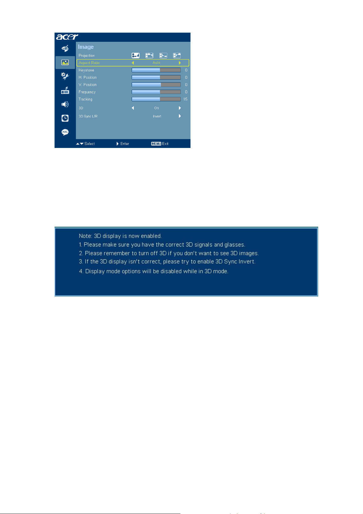
OSD :
− Add “3D”, “3D Sync L/R” in Image Page
− 3D : NVIDIA 3D, DLP 3D, off. Default is Off. All of acer 3D models are support both
NVIDIA and DLP. (V1.17 08/21 update)
− “3D Sync L/R” is adjustable when above "3D" is on. Otherwise gray out. When you
discover the inversion of the image depth (for your Left/Right eyes), do the invert
action to solve this condition. (V1.17 08/21 update)
When choose NVIDIA 3D , 3D Sync L/R is still gray out. (V1.18 09/30 update).
3D Sync L/R only enable for DLP 3D, otherwise it will be gray out (V1.18 09/30
update).
When 3D is enabled, Display Mode and Color temperature (in Color Page) is not
adjustable.
− Function disable :
When 3D is enabled, eView Management and all empowering function (eTimer,
eOpening, ePower) are gray out. eKey is disable (V1.18 09/30 update)
When meeting 60/120Hz (no matter 3D on or off, HSG only one set value), if
enduser adjust adjustable items (ex. brightness), the value will not been stored
and only for that use only.
− For DDP2430 models : 3D / 3D Sync L/R (V1.17 08/21 update) , only appear for
VGA/DVI/HDMI source. Disappear if other sources.
− For DDP2230/2431 models : no this limitation.
10
Page 11
If non-3D mode (120Hz), keep normal/same brightness.
Not support timing in 3D mode requirement
• 3D function can be opened when 50/60/100/120Hz.
• Refresh rate change to not supported 3D timings under 3D mode, please
show warning message of "Input Not Supported under 3D mode", to
enforce user to change back.
Reminder screen
11
Page 12
Electrical Specification
1. Timing Table
The PC timing is as following:
(For S5201):
Resolution Mode
VGA_60 59.940 31.469 25.175
VGA_72 72.809 37.861 31.500
640 x 480
800 x 600
1024 x 768
1152 x 864
1152 x 864 SXGA_85 84.990 77.094 121.500
1280 x 1024
1280 x 960
1400 x 1050 SXGA+_60 59.978 65.317 121.750
1600 x 1200 UXGA_60 60.000 75.000 162.000
640x480@60Hz PowerBook G4 59.940 31.469 25.170
640x480@67Hz PowerBook G4 66.667 35.000 30.240
800x600@60Hz PowerBook G4 60.317 37.879 40.000
1024x768@60Hz
1152x870@75Hz
1280x960@75Hz
1024x768@75Hz
1280 X 768
1280 x 720 WXGA_60 60.000 45.000 74.250
1280 x 800 WXGA_60 59.810 49.702 83.500
1440 x 900 WXGA+_60 59.887 55.935 106.500
1680 x 1050 1680x1050_60 59.954 65.290 146.250
1366 x 768 acer_16:9 59.790 47.712 85.500
1920 x1080 1920x1080_RB 60.000 66.587 138.500
1920 x1080 1920x1080_EIA 60.000 67.500 148.500
1024 x 600 acer_timing 60.000 37.500 50.400
VGA_75 75.000 37.500 31.500
VGA_85 85.008 43.269 36.000
VGA_120 119.518 61.910 52.500
SVGA_56 56.250 35.156 36.000
SVGA_60 60.317 37.879 40.000
SVGA_72 72.188 48.077 50.000
SVGA_75 75.000 46.875 49.500
SVGA_85 85.061 53.674 56.250
SVGA_120 119.854 77.425 83.000
XGA_60 60.004 48.363 65.000
XGA_70 70.069 56.476 75.000
XGA_75 75.029 60.023 78.750
XGA_85 84.997 68.677 94.500
XGA_120 119.804 98.958 137.750
SXGA_70 70.012 63.851 94.500
SXGA_75 75.000 67.500 108.000
SXGA_60 60.020 63.981 108.000
SXGA_72 72.000 76.970 134.600
SXGA_75 75.025 79.976 135.000
SXGA_85 85.024 91.146 157.500
QuadVGA_60 60.000 60.000 108.000
QuadVGA_75 75.000 75.000 126.000
PowerBook G4 60.004 48.363 65.000
PowerBook G4 75.061 68.681 100.00
PowerBook G4 75 75.20 126.00
i MAC DV (G3) 75.020 60.241 80.000
WXGA_60 59.870 47.776 79.500
WXGA_75 74.893 60.289 102.250
WXGA_85 84.837 68.633 117.500
Refresh rate
(Hz)
H-frequency
(kHz)
Clock
(MHz)
12
Page 13
(For S5201B/S5301WB):
Resolution Mode
VGA_60 59.940 31.469 25.175
640 x 480
720 x 400
800 x 600
1024 x 768
1152 x 864
1152 x 864 SXGA_85 84.990 77.094 121.500
1280 x 1024
1280 x 960
1400 x 1050 SXGA+_60 59.978 65.317 121.750
1600 x 1200 UXGA_60 60.000 75.000 162.000
640x480@60Hz Mac G4 59.940 31.469 25.170
640x480@67Hz MAC13 66.667 35.000 30.240
800x600@60Hz Mac G4 60.317 37.879 40.000
832x624@75Hz MAC16 74.546 49.722 57.280
1024x768@60Hz
1024x768@75Hz
1152x870@75Hz
1280 X 768
1280 x 720 WXGA_60 60.000 45.000 74.250
1280 x 800 WXGA_60 59.810 49.702 83.500
1440 x 900 WXGA+_60 59.887 55.935 106.500
1680 x 1050 1680x1050_60 59.954 65.290 146.250
1920 x1080 1920x1080_RB 60.000 66.587 138.500
1920 x1080 1920x1080_EIA 60.000 67.500 148.500
1366 x 768 acer_16:9 59.790 47.712 85.500
1024 x 600 acer_timing 60.000 37.500 50.400
640 x 480 VGA_120 119.518 61.910 52.500
800 x 600 SVGA_120 119.854 77.425 83.000
1024 x 768 XGA_120 119.804 98.958 137.750
VGA_72 72.809 37.861 31.500
VGA_75 75.000 37.500 31.500
VGA_85 85.008 43.269 36.000
VGA_70 70.087 31.469 28.3221
VGA_85 85.039 37.927 35.500
SVGA_56 56.250 35.156 36.000
SVGA_60 60.317 37.879 40.000
SVGA_72 72.188 48.077 50.000
SVGA_75 75.000 46.875 49.500
SVGA_85 85.061 53.674 56.250
XGA_60 60.004 48.363 65.000
XGA_70 70.069 56.476 75.000
XGA_75 75.029 60.023 78.750
XGA_85 84.997 68.677 94.500
SXGA_70 70.012 63.851 94.500
SXGA_75 75.000 67.500 108.000
SXGA_60 60.020 63.981 108.000
SXGA_72 72.000 76.970 134.600
SXGA_75 75.025 79.976 135.000
SXGA_85 85.024 91.146 157.500
QuadVGA_60 60.000 60.000 108.000
QuadVGA_75 75.000 75.000 126.000
Mac G4 60.004 48.363 65.000
MAC19 75.020 60.241 80.000
MAC21 75.061 68.681 100.00
WXGA_60 59.870 47.776 79.500
WXGA_75 74.893 60.289 102.250
WXGA_85 84.837 68.633 117.500
Refresh rate
(Hz)
H-frequency
(kHz)
Clock
(MHz)
13
Page 14
The DVI_D & HDMI (HDCP) Established timing is as following:
(For S5201):
Resolution Mode
VGA_60 59.940 31.469 25.175
VGA_72 72.809 37.861 31.500
640 x 480
800 x 600
1024 x 768
1152 x 864
1280 x 1024
1280 x 960 QuadVGA_75 75.000 75.000 126.000
1400 x 1050 SXGA+_60 59.978 65.317 121.750
1600 x 1200 UXGA_60 60.000 75.000 162.000
640x480@60Hz PowerBook G4
640x480@67Hz PowerBook G4
800x600@60Hz PowerBook G4
1024x768@60Hz PowerBook G4
1152x870@75Hz PowerBook G4
1280 x 960@75Hz PowerBook G4
1024x768@75Hz i MAC DV (G3)
1280 x 768
1280 x 720 WXGA_60 60.000 45.000 74.250
1280 x 800 WXGA_60 59.810 49.702 83.500
1440 x 900 WXGA+_60 59.887 55.935 106.500
1680 x 1050 1680x1050_60
1366 x 768 acer_16:9 59.790 47.712 85.500
1920 x1080 1920x1080_RB
1920 x1080 1920x1080_EIA
1024 x 600 acer_timing 60.000 37.500 50.400
VGA_75 75.000 37.500 31.500
VGA_85 85.008 43.269 36.000
VGA_120 119.518 61.910 52.500
SVGA_56 56.250 35.156 36.000
SVGA_60 60.317 37.879 40.000
SVGA_72 72.188 48.077 50.000
SVGA_75 75.000 46.875 49.500
SVGA_85 85.061 53.674 56.250
SVGA_120 119.854 77.425 83.000
XGA_60 60.004 48.363 65.000
XGA_70 70.069 56.476 75.000
XGA_75 75.029 60.023 78.750
XGA_120 119.804 98.958 137.750
SXGA_75 75.000 67.500 108.000
SXGA_85 84.990 77.094 121.500
SXGA_60 60.020 63.981 108.000
SXGA_72 72.000 76.970 134.600
SXGA_75 75.025 79.976 135.000
SXGA_85 85.024 91.146 157.500
WXGA_60 59.870 47.776 79.500
WXGA_75 74.893 60.289 102.250
WXGA_85 84.837 68.633 117.500
Refresh rate
(Hz)
59.940 31.469 25.170
66.667 35.000 30.240
60.317 37.879 40.000
60.004 48.363 65.000
75.061 68.681 100.00
75.000 75.200 126.000
75.020 60.241 80.000
59.954 65.290 146.250
60.000 66.587 138.500
60.000 67.500 148.500
H-frequency
(kHz)
Clock
(MHz)
14
Page 15
480i 60 15.73 27.000
480p 60 31.47 27
576i 50 15.63 27.000
576p 50 31.25 27.000
720p_60 60 45.00 74.25
Video(HDMI)
720p_50 50 37.50 74.25
1080i_60 60 33.75 74.25
1080i_50 50 28.13 74.25
1080p 60 67.5 148.5
1080p 50 56.26 148.5
1080p 24 27.00 74.25
1080p 23.98 26.97 74.175
(For S5201B/S5301WB) :
Resolution Mode
VGA_60 59.940 31.469 25.175
VGA_72 72.809 37.861 31.500
640 x 480
720 x 400
800 x 600
1024 x 768
1152 x 864
1152 x 864 SXGA_85 84.990 77.094 121.500
1280 x 1024
1280 x 960
1400 x 1050 SXGA+_60 59.978 65.317 121.750
1600 x 1200 UXGA_60 60.000 75.000 162.000
640x480@60Hz Mac G4 59.940 31.469 25.170
640x480@67Hz MAC13 66.667 35.000 30.240
800x600@60Hz Mac G4 60.317 37.879 40.000
832x624@75Hz MAC16 74.546 49.722 57.280
1024x768@60Hz
1024x768@75Hz
1152x870@75Hz
VGA_75 75.000 37.500 31.500
VGA_85 85.008 43.269 36.000
VGA_120 119.518 61.910 52.500
VGA_70 70.087 31.469 28.3221
VGA_85 85.039 37.927 35.500
SVGA_56 56.250 35.156 36.000
SVGA_60 60.317 37.879 40.000
SVGA_72 72.188 48.077 50.000
SVGA_75 75.000 46.875 49.500
SVGA_85 85.061 53.674 56.250
SVGA_120 119.854 77.425 83.000
XGA_60 60.004 48.363 65.000
XGA_70 70.069 56.476 75.000
XGA_75 75.029 60.023 78.750
XGA_85 84.997 68.677 94.500
XGA_120 119.804 98.958 137.750
SXGA_70 70.012 63.851 94.500
SXGA_75 75.000 67.500 108.000
SXGA_60 60.020 63.981 108.000
SXGA_72 72.000 76.970 134.600
SXGA_75 75.025 79.976 135.000
SXGA_85 85.024 91.146 157.500
QuadVGA_60 60.000 60.000 108.000
QuadVGA_75 75.000 75.000 126.000
Mac G4 60.004 48.363 65.000
MAC19 75.020 60.241 80.000
MAC21 75.061 68.681 100.00
WXGA_60 59.870 47.776 79.500 1280 x 768
WXGA_75 74.893 60.289 102.250
Refresh rate
(Hz)
H-frequency
(kHz)
Clock
(MHz)
15
Page 16
WXGA_85 84.837 68.633 117.500
1280 x 720 WXGA_60 60.000 45.000 74.250
1280 x 800 WXGA_60 59.810 49.702 83.500
1440 x 900 WXGA+_60 59.887 55.935 106.500
1680 x 1050 1680x1050_60 59.954 65.290 146.250
1920 x1080 1920x1080_RB 60.000 66.587 138.500
1920 x1080 1920x1080_EIA 60.000 67.500 148.500
1366 x 768 acer_16:9 59.790 47.712 85.500
1024 x 600 acer_timing 60.000 37.500 50.400
480p 60 31.47 27
576p 50 31.25 27.000
720p_60 60 45.00 74.25
720p_50 50 37.50 74.25
Vedio(HDMI)
1080i_60 60 33.75 74.25
1080i_50 50 28.13 74.25
1080p 60 67.5 148.5
1080p 50 56.26 148.5
1080p 24 27.00 74.25
1080p 23.98 26.97 74.175
(For all series):
YPbPr support timing is as following:
Signal format fh(kHz) fv(Hz)
480i(525i)@60Hz 15.73 59.94
480p(525p)@60Hz 31.47 59.94
576i(625i)@50Hz 15.63 50.00
576p(625p)@50Hz 31.25 50.00
720p(750p)@60Hz 45.00 60.00
720p(750p)@50Hz 37.50 50.00
1080i(1125i)@60Hz 33.75 60.00
1080i(1125i)@50Hz 28.13 50.00
1080P@60HZ 67.5 60.00
1080P@50Hz 56.26 50.00
1080P@24Hz 27.00 24.00
1080P@24Hz 27.00 24.00
1080P@23.98Hz 26.97 23.98
Video, S-Video support timing is as following:
Video mode fh(kHz) fv(Hz) fsc(MHz)
NTSC 15.73 60 3.58
PAL 15.63 50 4.43
SECAM 15.63 50 4.25 or 4.41
PAL-M 15.73 60 3.58
PAL-N 15.63 50 3.58
PAL-60 15.73 60 4.43
NTSC4.43 15.73 60 4.43
16
Page 17
2. Characteristics of inputs/outputs
Signal Parameter Min Type Max
RDATA
GDATA
BDATA
Impedance 75 Ohm
Amplitude 0.7 Volts peak-to-peak
Black pedestal 0 Volts
Pixel Clock 170 M Hz
GDATA_SO
G
Impedance 75 Ohm
Amplitude 1 Volts peak-to-peak
Video amplitude 0.7 Volts peak-to-peak
Sync amplitude 0.3 Volts peak-to-peak
Black pedestal 0 Volts
Pixel Clock 170 M Hz
HDATA
Impedance 1 K ohm
Amplitude, low level 0 0.8 volt
Amplitude, high level 2.5 5 Volt
Frequency 31 99 K Hz
VDATA
Impedance 1 K ohm
Amplitude, low level 0 0.8 volt
Amplitude, high level 2.5 5 Volt
Frequency 48 120 Hz
Amplitude, low level 0 0.8 volt SDADATA
Amplitude, high level 3 5 Volt
Amplitude, low level 0 0.8 volt SCLDATA
Amplitude, high level 3 5 Volt
RXD Amplitude -25 25 Volt
TXD Amplitude -13.2
CVBS
Luminance
Amplitude, total (video+
sync)
1 Volts peak to peak
13.2 Volt
Amplitude, video 0.7 Volts peak to peak
Amplitude, sync 0.3 Volts peak to peak
Impedance 75 ohm
Amplitude 700 m Volts peak to peak CVBS
Chroma
Audio
Impedance 75 ohm
Impedance (audio in) 10 Kohm
Amplitude (audio in) 500 mVolts rms
Bandwidth 300H
16kHz
z
S/N Ratio 40 %
Total Harmonic
10 %
Distortion
Microphone
Transducer Principle Dynamic
Impedance 300
Frequency response 600
1K ohm
16k
3. Electrical Interface Character
Interface Definition
Hz
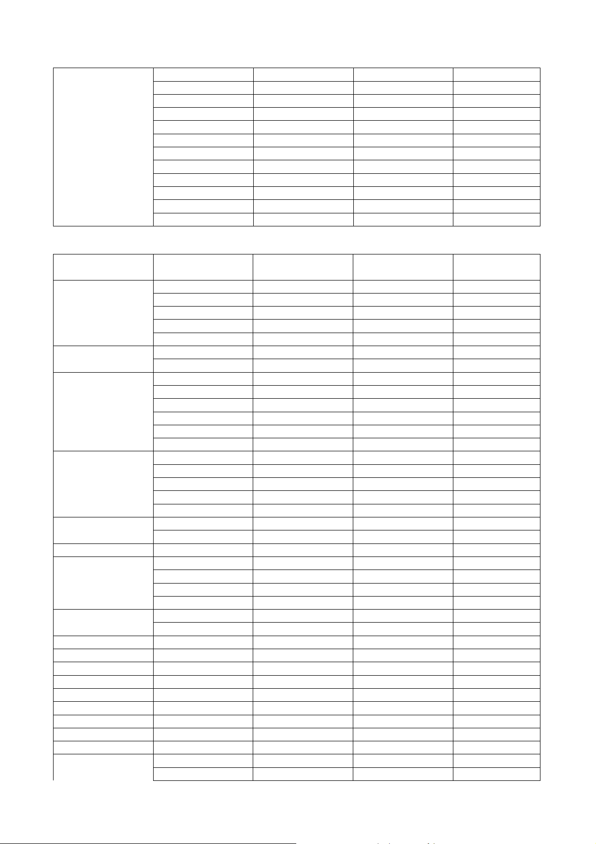
15 pin definition of the mini D-sub male for DDC2B protocol
17
Page 18
1
6
5
10
11
15
Pin Definition Pin Definition Pin Definition Pin
1
Red video
(Pr)
2
5 NC 6
Green Video
(Y)
Red Video
Return
3
7
Blue Video
Green Video
(Pb)
Return
9 DDCP 5V 10 GND 11 GND 12
13
Horizontal
Sync
14 Vertical Sync 15
Data clock
(SCL)
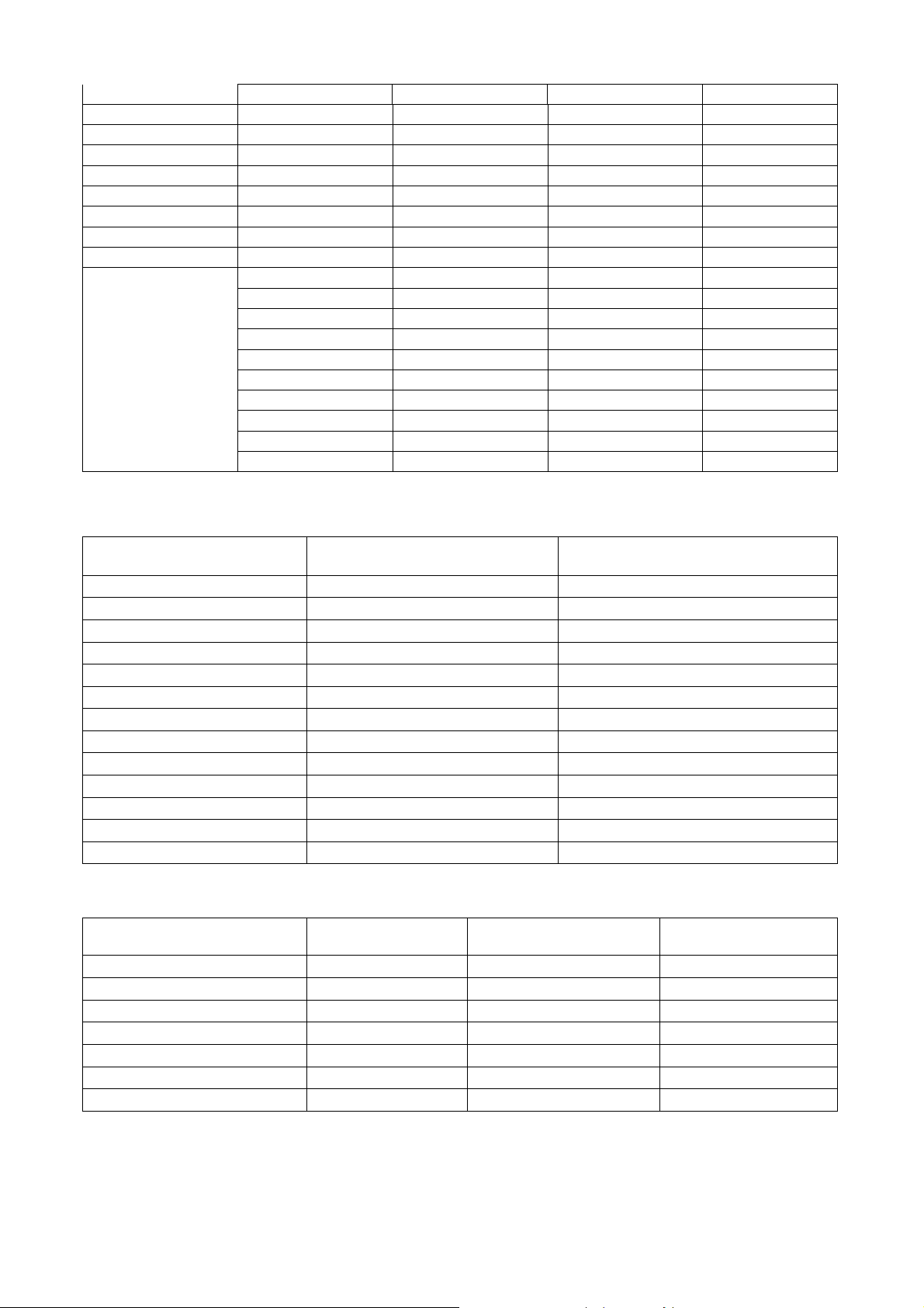
Video & Component Input
1111
Pin Definition
Composite input
Composite input
Composite inputComposite input
1
Composite video
input
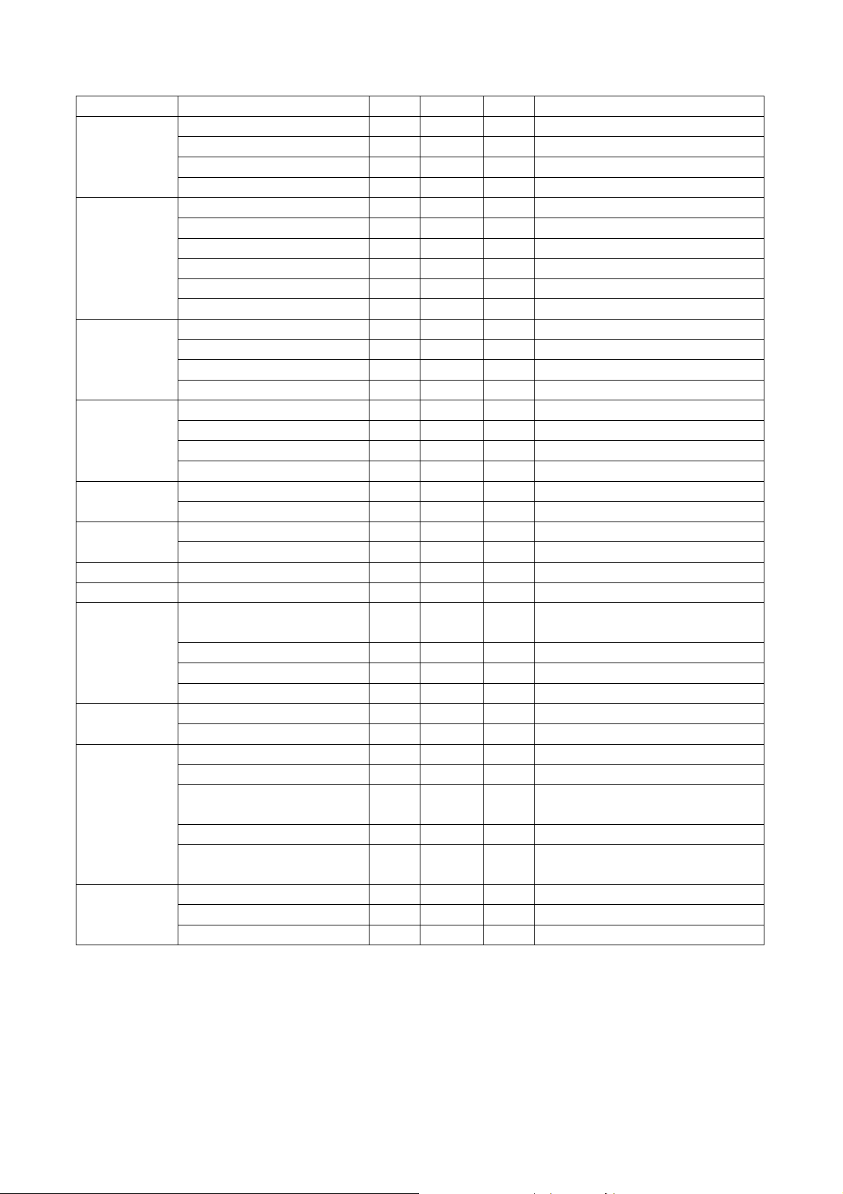
S-Video input
Pin Description
3
241
1 GND
2
GND
3 Luminance
4 Chroma
Definition
4 NC
8
Blue Video
Return
Bi-directional
data (SDA)
RS232 Control Port
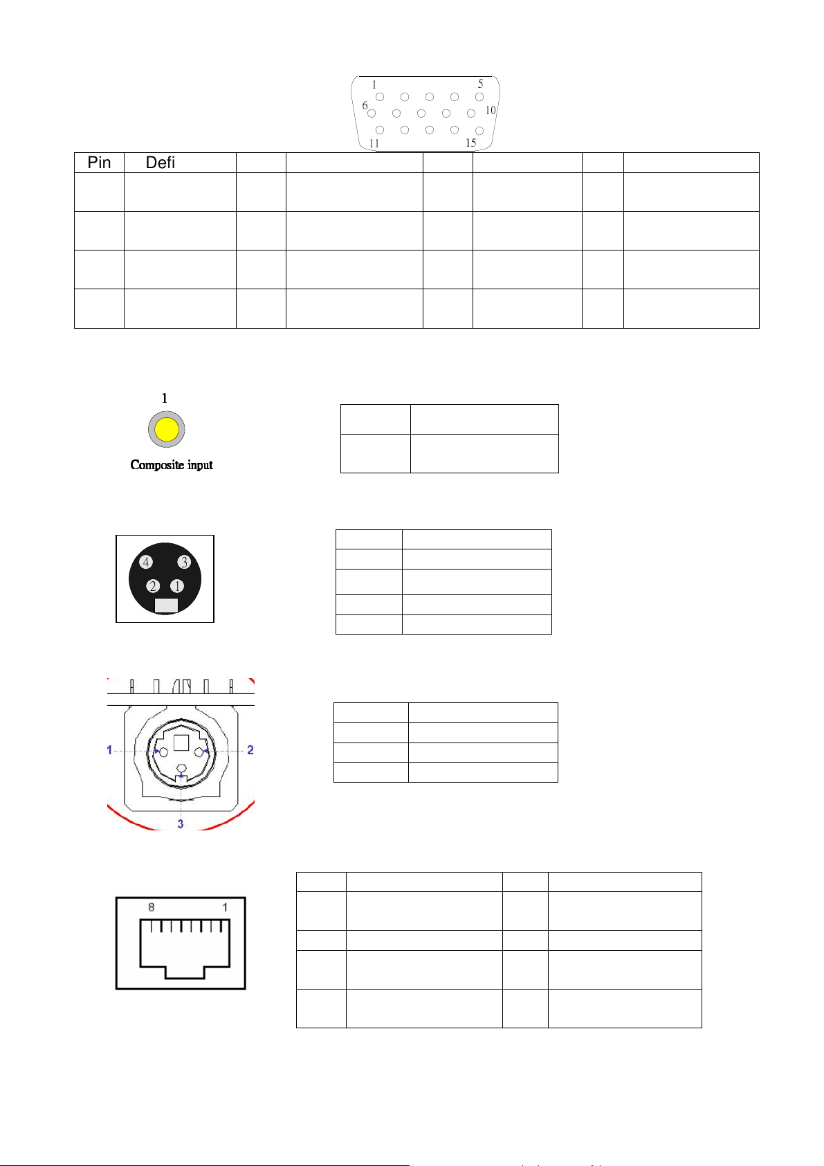
LAN Control Port
Pin Description
1 TX
2 RX
3 GND
Pin
1 TD+ 5
Signal Pin
Signal
Common Mode
Termination
2 TD- 6 RD-
3 RD+ 7
4
Common Mode
Termination
8
Common Mode
Termination
Common Mode
Termination
18
Page 19
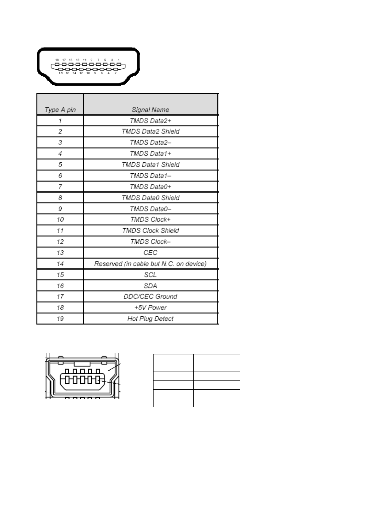
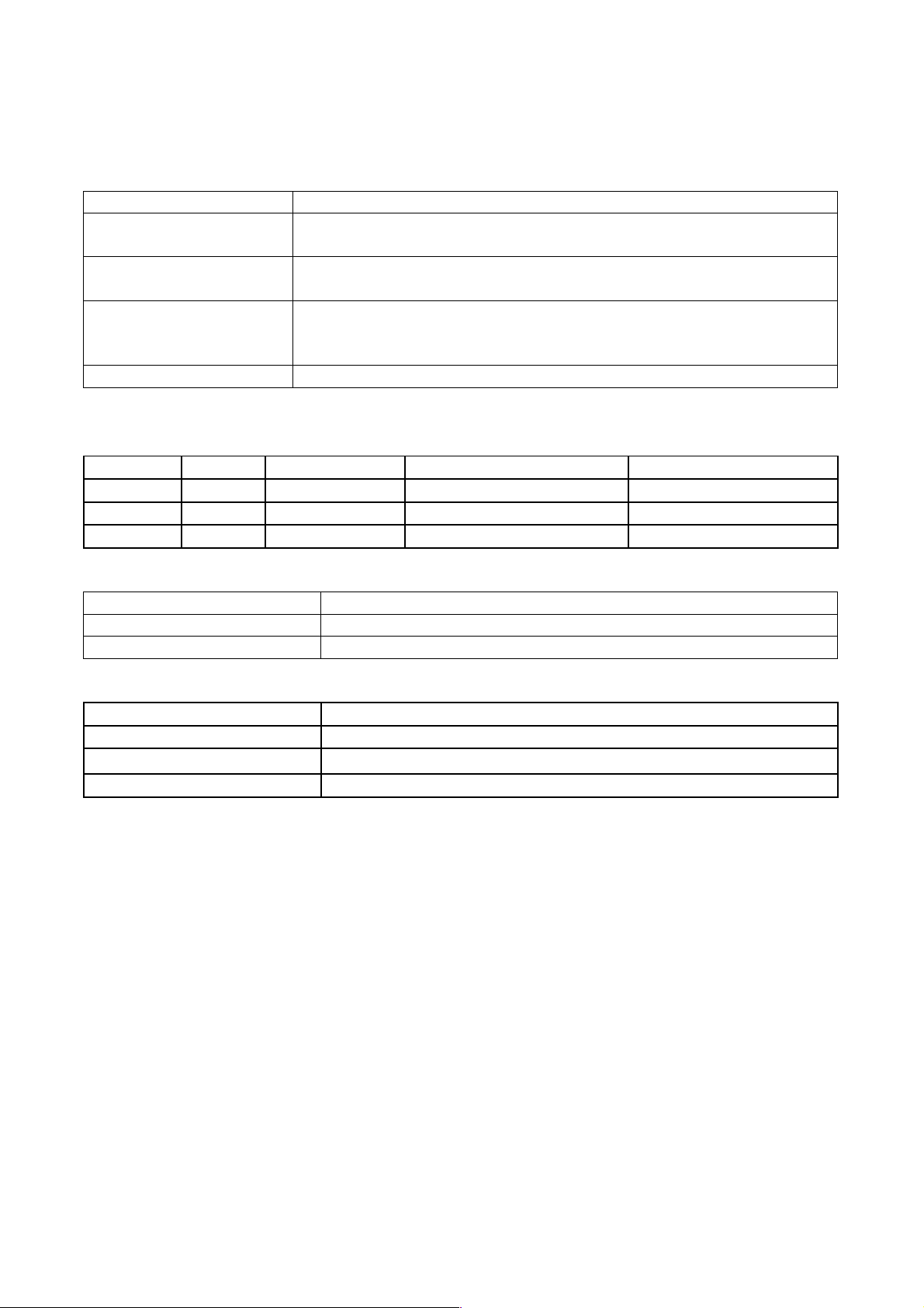
HDMI Input
Mini USB TYPE B (for S5201B/S5301WB)
Pin Description
1 Vbus
2 D3 D+
4 ID
5 GND
19
Page 20
Power Supply Specification
1. Input Power Specification
Specification Description
Input Voltage Range
Frequency Range
The unit shall meet all the operating requirements with the range
90 ~ 264 VAC
The unit shall meet all the operating requirements with an input
frequency range 47 Hz ~ 63 Hz
Normal operation: 352W (Max)
Power Consumption
standby mode: < 1W, at 100 ~ 240VAC, monitor out function off,
LAN function off, 12V outlet off
Regulation Efficiency 80 % (typical) measuring at 115Vac and full load
2. Output Power Requirement
The power supply can provide DC output as below:
NO. Voltage
1 +12 V
2 +5V
3 +380V
Regulation Load Current Range Ripple & Noise
10 % 0 A ~ 2 A 240 mV
5 % 0.03 ~ 0.1A 100mV
370~400 0.2A 25V
3. Lamp Power specifications
Specification Description
Applicable Lamp Nor: 230W, Eco: 170W, AC operation
Starting pulse from Ignitor 2.1KV Min.
4. Power Protection
Item Criteria
Short protection No damage
OVP
5V: 6 ~6.5V, 12V: 13 ~16V, 380V: 450 ~490V <30ms
OPP DC-DC 120~160%
5. Surge test: Meet EN61000-4-5
L
N 1KV, L, N PE 2KV, Criteria B
6. Electrical Fast Transients (EFT):Meet EN61000-4-4
2 KV, Criteria B
7. Voltage Dips: Meet EN61000-4-11
0% 250 cycle; 40%, 70% reduction 5 cycle, no damage
8. Harmonic current test: Meet EN61000-3-2
20
Page 21
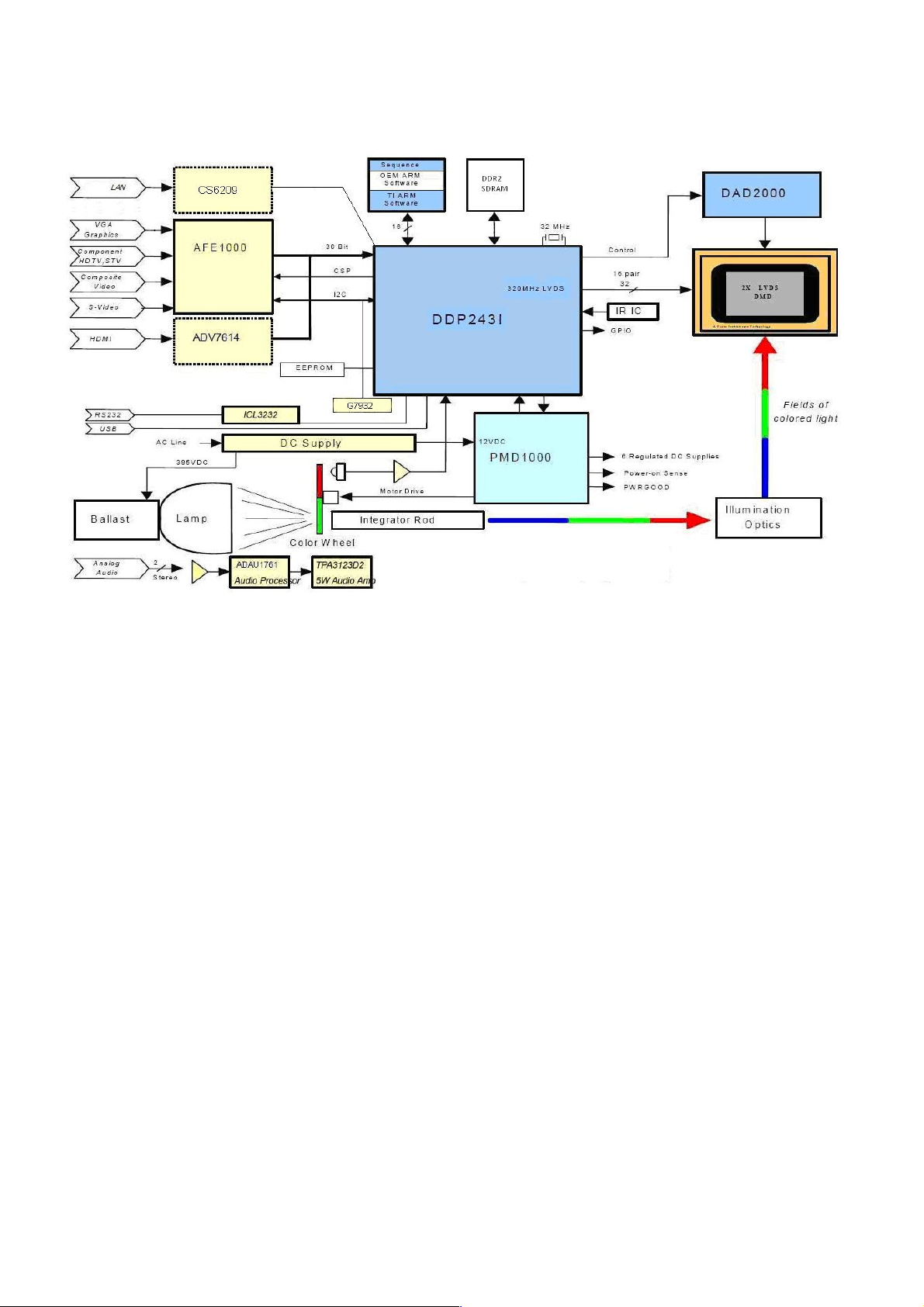
System Block Diagram
21
Page 22
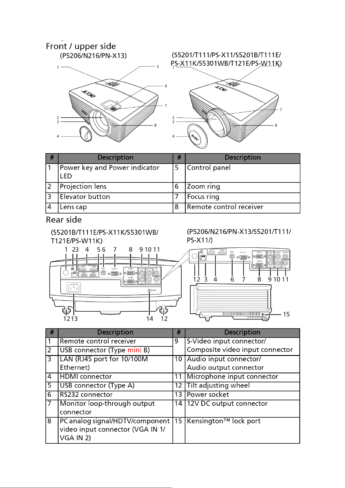
Product Overview
22
Page 23
23
Page 24
24
Page 25
25
Page 26

Chapter 2 System Utilities
Firmware Upgrade SOP
Basic Operating
Low-Power Standby Mode::::
This mode is applied for normal situation. If you want to enter this mode, you could just
plug in power cord. Power LED will show Red for 1 sec then show Orange.
When the power LED shows Red, it means system is not ready for low-power standby.
In another word, if the power LED shows Orange, it means system is in low-power standby
mode and the whole system is not supported by power except MCU and its related circuits.
Meanwhile, the power consumption should under 1W.
Download Mode::::
This mode is applied for Download firmware or debug.
One method to enter this mode is that you should press and hold keypad Power and
Menu together, then plug in power cord. Release the two keypads until the Power LED
show Power, Lamp and Temp LED show Red continuously
The other method is to type RS-232 Command:<CR>*Stby=H#<CR>
In full-power standby mode, system will be supported by full power but not turn on
projector. You can use DLP composer and communicate with DLP ASIC. Thus, you should
download firmware in this mode.
Full-Power Standby Mode::::
This mode also can download FW, you should press and hold keypad Power and
Source together, then plug in power cord. Release the two keypads until the Power LED
show Red continuously.
26
Page 27

Download MCU Code, LAN and Firmware
1. Download WT61P803/WT6702 MCU Code::::(in Low - Power Standby, for
S5201 all series)
Condition::::
Situation 1:MCU code is empty (The 1st time to plug in power cord)
Situation 2:MCU version update
System Action::::
System needs a few sec to download MCU automatically.
Downloading::::POWER and Temp LED will show red.
Download Success::::System will go back Low-Power standby mode and Power
LED will show red.
Download Fail : POWER and Lamp LED will show red.
Notice::::
Do NOT interrupt power when downloading.
2. Download CS6209 LAN Firmware::::(for S5201)
Firmware Download Procedure::::
1. Enter Factory Mode page 7
2. Under CS6209, set Lan Download On
3. Turn off projector, and the projector will download LAN firmware automatically.
System Action::::
Downloading::::POWER and LAMP LED will show RED.
Download success : system will go back low-power standby mode and Power
LED will show RED.
3. Download AWIND Firmware::::(for S5201B/S5301WB Extension board)
Awind firmware Upgrade procedure::::
1. Turn on projector
2. Connect PC and projector RJ45 connector with CAT 5 wire directly
3. Change projector source to LAN source(must enter OSD to turn on LAN first)
4. Wait about 10~20 sec
5. Open PC Browser and enter 192.168.100.10
6. Please connect to web and click "Advance" to log in as root. (hint:
password->123456)
27
Page 28
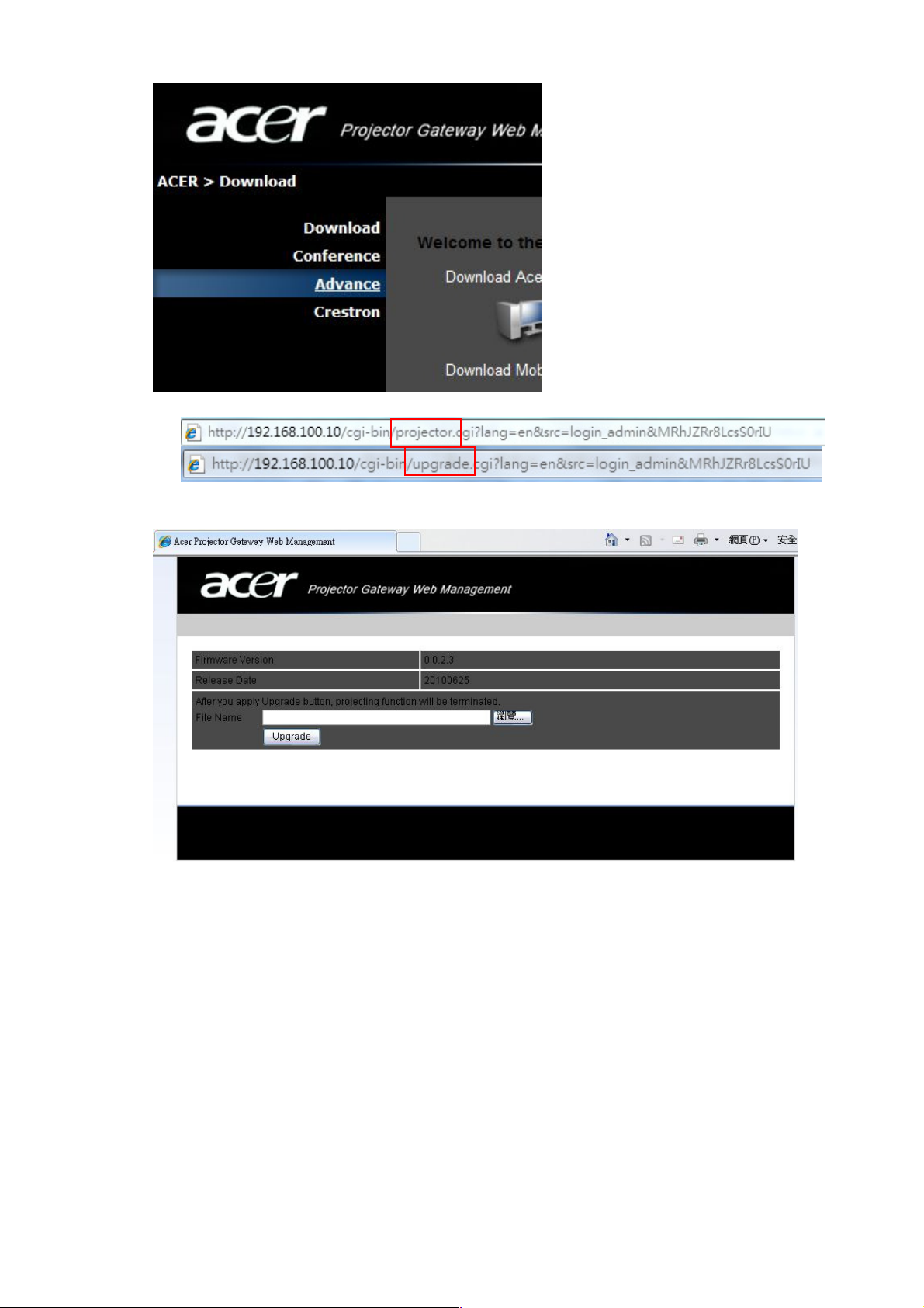
7. after login it, modify the web address, modify “projector” to “upgrade”, as below
8. If your connection success, you will see following web:
9. Select image file (*.img) and press Upgrade.
10. Wait count down to finish upgrading.
28
Page 29
4. Download Main Firmware(For all series)::::
DLP Composer LIte Installation Process
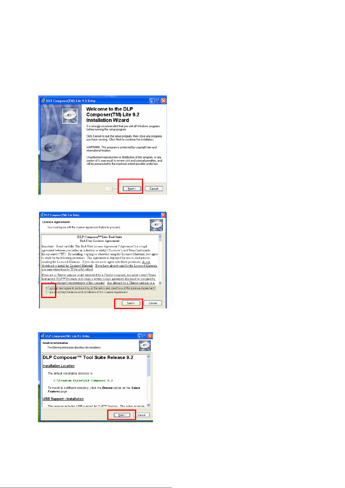
(1) Installation
1. Double click the Setup file for DLP Composer Lite 9.0 or above version.
2. When the Installation Wizard appears, click “Next”.
3. Select to accept the License Agreement, than click “Next”
4. Click “Next” in the following steps to continue installation process.
29
Page 30
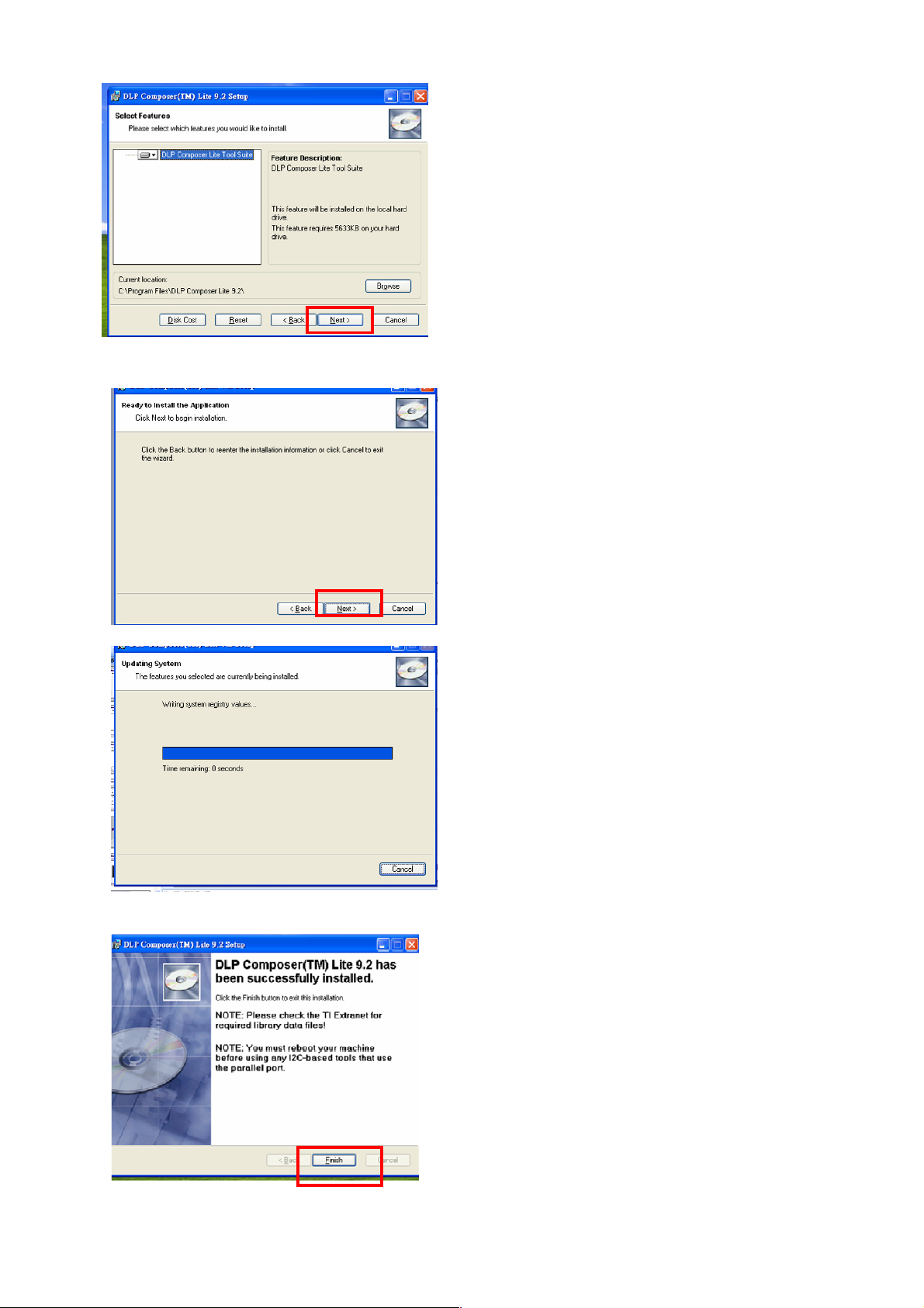
Note:
The default installation directory is:
C:\Program Files\DLP Composer Lite9.2
If you want to install to a different directory (perhaps
alongside a prior release of DLP Composer™ Lite),
click the "Browse" button on the "Select Features"
page.
5. When finishing installation, click “Finish”, and then restart your computer to complete the
installation process.
30
Page 31
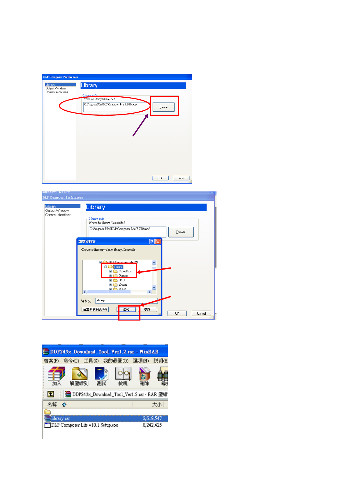
(2) Setting for your first use
Click
Click Click
Click
““““
Browse
BrowseBrowse
Browse
””””
to
to to
to
select
select select
select
Click the
Click the Click the
Click the
library
librarylibrary
library
Select Library:
1. When start to use this program to download at first time, you need to check if the library
folder is existed under the path of Library.
path for library files
path for library files
path for library filespath for library files
folder to assign
folder to assign
folder to assign folder to assign
the path.
the path.
the path.the path.
Then Click
Then Click ““““OK
Then Click Then Click
2. Check if there are library files in the assigned path. If not, unzip the library file into the
path. (You can unzip “DDP243x_Download_Tool_ Ver1.2.rar” to get the library.)
OK””””....
OKOK
31
Page 32

Set communication (for download by RS232):
1. Select “Edit”->”Preference”.
2.
Select “Communications”-> “Serial Port” -> ”Config”.
3. Make sure the settings are the same as below figure-> Click ”OK”.
4. Click ”OK”.
32
Page 33

(3) Download Procedure
How to download
Hardware required
1. Standard RS232 Download cable (Mini Din 3 pin male for Both terminals)
2. Personal computer or laptop computer
Software required
1. DLP Composer Lite program
2. New version FW
Download procedure
a. Connect RS-232 cable to PC and projector
b. Let projector be in Download Mode or Full-power standby mode :
-> Press and hold keypad Power and Menu together, then plug in power cord.
-> Release the two keypads.
-> Power, Lamp and Temp LED show Red continuously.
c. Execute DLP Composer Lite 9.0 or above version program
d. To select the RS-232 communications interface, choose "Preferences" from the
"Edit" menu, click the "Communications" page and choose "Serial Port".
33
Page 34

e. Click on “Flash Loader” and browse the image file (new version firmware)
f. Select Complete Image Download, and make sure to check “Skip Boot loader area
(32KB)”
g. Press “Reset Bus” and check the status which should show “Bus Reset”
h. Press “Start Download” to begin update new firmware.
i. Press “Yes” to continue. (when download new firmware and power LED will show
purple.)
34
Page 35

j. Wait till composer lite notice download complete.
When download complete, LED signal on projector will show standby status.
Method to enter factory menu
1. Press keypad Power and image will show Power Down OSD function
2. Press keypad Left twice then press Menu, then enter the Factory mode.
Step 1
Step 2
35
Page 36

EDID Upgrade SOP
Link to Main
Link to Projector :
Link to Projector :
Equipment List
1. PC : with parallel (printer) port
2. EDID Board
3. Printer cable : 25pin male-female (connect PC to EDID board)
4. D-sub cable* : with full 15pin (connect EDID board to Projector)
5. HDMI cable*(connect EDID board to Projector)
6. DVI cable* (connect EDID board to Projector)
(*Note: Not every model’s EDID input (D-sub, DVI, HDMI) is the same. Need to check what
kind of file you need before download.)
Setup Equipment
1. Let projector be in Full-power standby mode (Press “Power” and “Source” and plug in
power cord into Projector immediately.)
2. Connect between PC, EDID board and the Projector:
DVI-D DDC download
(no need in X1130/ X1230/
X1230S/ X1235/ X1230K
series)
For
“25pin male-female
cable” (normal
printer cable)
PC with parallel
(printer) port
3. Need to set Jumper before using EDID board :
<Jumper setting :>
J6 : 1,2 short
J8 : 1,2 short
J10 : short
EDID board
For HDMI DDC
download
X1130/ X1230/ X1230S/
X1235/ X1230K series)
Please ignore this
connector
(no need in
board :
For D-sub DDC
download
36
Page 37

3. How to use Download Tool :
Software Installation, Un-installation :
Unzip the “Q-EDID” program files in the same directory.
Install Q-EDID tool : Execute “Install Q-EDID.BAT” to install & register EDID Board
into the computer.
Un-install Q-EDID tool : If you want to uninstall this tool, execute “Uninstall
Q-EDID.BAT”, then it will remove EDID Board from the computer.
How to use Download Tool :
(1) Execute EDID Tools V0.16:
1. Run “Q-EDID-V016.exe”.
2. Program will appear as below picture.
(2) Write EDID:
• When write D-SUB/DVI EDID:
1. EDID Type Selection : Choose ‘‘EDID 128 Bytes’’.
2. Open Files : Click “Open File” to select file “*.DDC”
(Note : If your DDC file name is not like “*.DDC” (e.g. “*.2dc”), please rename it to “*.DDC”)
3. Write EDID : Click “Write EDID”, and it will execute writing process.
4. While complete, it will show message as ’’Write EDID OK…’’.
(Note : Check cable connection before write. It will show Write EDID OK even the connection
is not stable.)
37
Page 38

Step1
Step2
Step3
Step4
(3) Read EDID:
• Read D-SUB/DVI EDID:
1. EDID Type Selection : Choose ‘‘EDID 128 Bytes’’
2. Read EDID : Click “Read EDID”.
3. While complete, it will show message’’ Read EDID OK… ‘’, and the read-out DDC will
show in the table in program.
Important Note :
Be reminded to connect Only One port every time, because the software will not be able
to identify the command signal from which port.
After connecting all equipment, always read DDC before writing DDC to ensure the
connection status is OK for writing DDC.
38
Page 39
Serial Number Upgrade SOP
Hardware required
1. Standard RS232 Download cable
2. Personal computer or laptop computer
Software required
1. Acer_Service_Tool(Data)_3.1.exe
When need to use this Serial Number Upgrade program:
When it’s time to replace Main board for repair, it’s necessary to rewrite original S/N and
some adjustment values into new Main board by the following process.
Upgrade procedure
1. Prepare the download equipment: RS232 cable connect to PC and projector
2. Plug power cord into projector, and the projector will be in stand by mode.
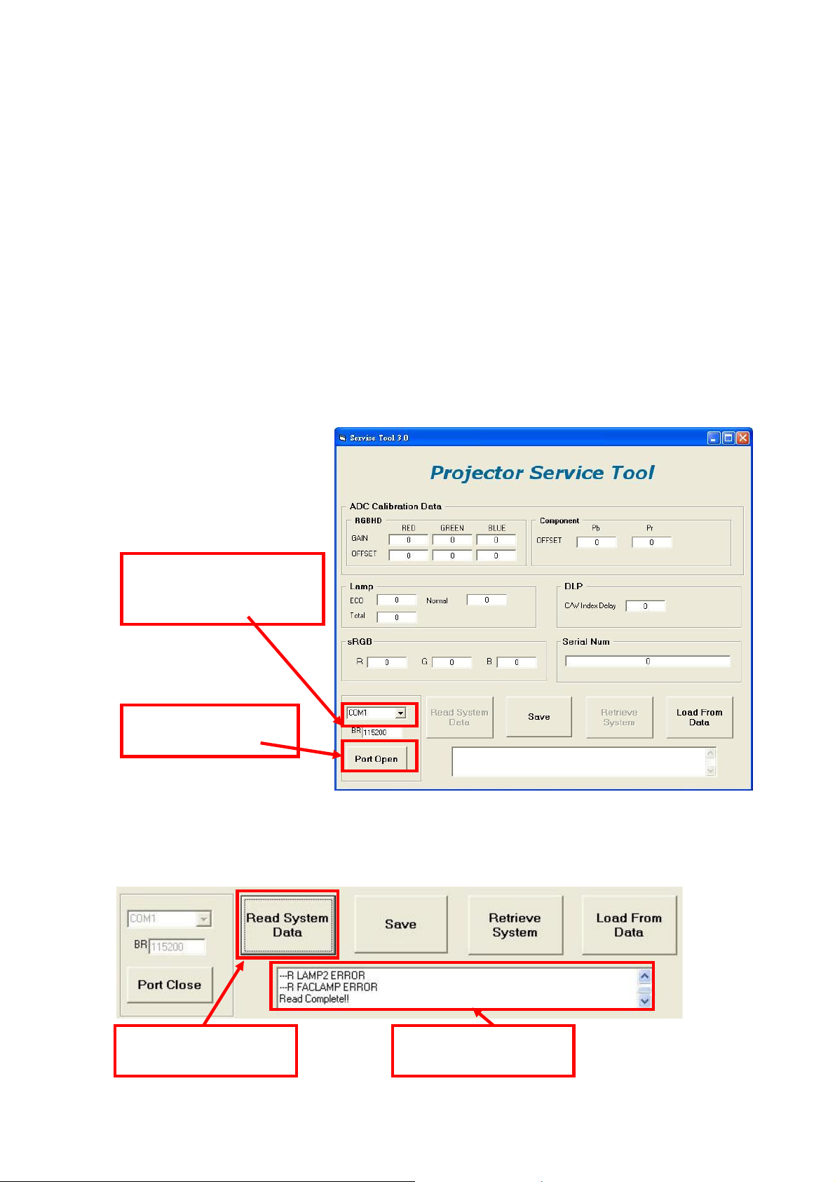
3. Execute “Acer_Service_Tool(Data)_3.1.exe”, and it will appear as below picture.
4. Change to connected COM port and Click “Port Open” icon.
4-1. Change to
connected COM Port
number
4-2. Click “Port
Open”
5. Read data from original Main board:
Click “Read system Data”, and it will read the Adjustment data (except Auto
keystone data) & Serial Number from projector and show the “Read complete”
message in information block.
5-1. Click this icon to
read all data
5-2. Show “Read
Complete!”
39
Page 40

6. Click “Save” to save data into the assigned file name.
6-2. This window will
pop out, and it shows
the file saving folder.
6-3. Enter file name here.
Suggest to use Serial
Num as the file name.
6-4. Click “Save” to save
data.
6-1. Click “Save” icon.
7. Change new Main board:
(1) Unplug power cable and RS232 cable from projector, and change new Main board
into Projector.
(2) After changing Main board, reconnect power cable and RS232 cable into
Projector.
8. Write S/N & data into new Main board:
Press “Retrieve System” and write Data & SN to projector.
9. “Load from data” & “Retrieve System” :
(1) Click “Load from data” and select load file.
(2) Click “Retrieve System” to write the values into main board.
9-1. Click “Load From
Data” to load data.
9-2. Select the file
source
10. Click “Retrieve System”
to write data.
9-3. Click “Load” to
finish file load.
40
Page 41

Chapter 3 System Disassembling and Replacement
2
IR 3pin Wire
Main Unit Disassembling
Tool : Screw Driver --Hex (#4-40) and Cross(Mechanical : M3,M4, Opt.Engine :M2)
Process :
Step Description Tool
(1) Disassemble the
screw*5(M3*L8) in the lowercase
and screw*2 (M2.5*L10) in the
1
inlet and outlet case.
(2) Take off the lamp-door.
(1) Disassemble the screw*3
(M3*L6) connecting the U/C with
the machine(you may need to
disclose the film on the upper
2
case).
(2) Hit the inlet-case to loose the
hook and at the same time lift the
upper case.
4
1
1
2
Hook in U/C
3
screw
driver
5
3
screw
driver
(1) Untie the tie in the engine and
loose the wire in it.(Figure1)
(2) Disassemble the screw*1
(M3*L8) connecting the F/C with
the L/C.(Figure2)
3
(3) Extract the I/R 3pin wire in the
main board and take off the front
case. (Figure 3,4)
Attention :DON'T TOUCH OR
BREAK THE LENS.
Figure1
Figure4
Hit the inlet case to
loose the hook
Figure2
at the same
time lift the
upper case
Figure3
Notice: Please release
the IR wire before take
off the Front Case.
41
Page 42

(1) Disassemble the screw*6(Hex
4
5
3pin
wire
#4-40*L6), then take off the
R/C.(Figure1).
Figure1
1 2 3 4
5 6
Figure2
loose these wires
1
2
3
(2) Disassemble the screw*5
4
(M3*L6) and loos the wires
connecting the engine and the
MB.
(3) Take off the SHD of the main
board.(Figure2)
(1) Extract all the wires in the
mainboard and loose the wire in
clips.(Figure1/2)
(2) Take off the ourlet case and
5
the Fans*2.
(3) Take off the main board.
Attention: DON'T TWIST THE
PIN UNDER THE M/B.
Figure1 Figure2
CW wire
inlet fan
IR wire
ballast
5pin wire
CW
speaker
twins fan wire
blower wire
outlet speaker wire
screw
driver
screw
driver
(1) Dismantle the screws*2
(M3*L6) to loose the EXTENSION
BD.(Figure1)
6
(2) Dismantle the STAND
OFF(M3 D6*9L) and screws*2
(M3*L6) on M/B.(Figure2,3)
Note:
Circuit boards > 10cm2 has been highlighted with the yellow
rectangle as above image shows. Please detach the Circuit boards
and follow local regulations for disposal.
Figure1
EXTENSION B D
Note:
Circuit boards > 10cm2 has been highlighted with the yellow
Figure2
Figure3
rectangle as above image shows. Please detach the Circuit boards
and follow local regulations for disposal.
screw
driver
42
Page 43
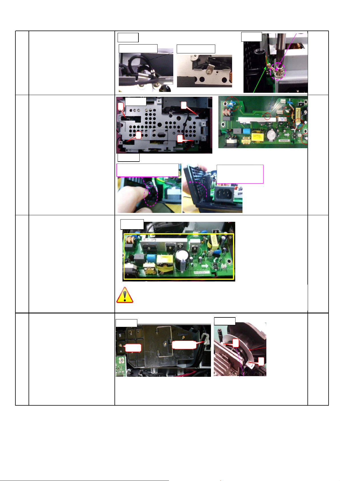
(1) Dismantle the screws *2
Figure1
Figure2
inlet case)
(M3*L6) to loose the two
wires.(Figure1)
7
(2) Dismantle the Grounding
screw (M4*L6) in the shield and
loose the Grounding wire.
(Figure2)
S5201/5201B
Figure2
S5301WB
(1) Dismantle the screws*4
(M3*L8) connecting the PB shield
and the L/C, then take off the
shield. (Figure1)
8
(2) Take off the inlet case
following the way indicated
below.(Figure2), then extract all
the wires in the power board.
9 (3) Take off the power board.
Figure1
4
2
At first, push here. (Take apart
Figure3
1
3
screw
driver
Along arrow, pull inlet
case and can take
apart inlet case.
(1) Extract the white lamp wire in
the lamp box, and disassemble
the screw*1(M3*L6) connecting
the lamp module in the machine,
then take off the lamp module.
10
(Figure1)
(2) Dismantle the screw*2(M3*L6)
of the BKT in the neck of the
engine and take off the
BKT.(Figure2)
Figure 1
screw
Circuit boards > 10cm2 has been highlighted with the yellow
Note:
rectangle as above image shows. Please detach the Circuit boards
and follow local regulations for disposal.
Figure 2
lamp wire
2
1
screw
driver
43
Page 44

(1) Disassemble the screw*3
1
1
Tool
1
2
(M2.5*L10), then take off the
engine. (Figure1)
11
(2) Disassemble the screw*2
(M3*L8) and take off BKT under
the engine. (Figure2)
Figure1
Figure2
3
2
1
2
1
screw
driver
(1) Take off the ballast mylar
(Figure1)
(2) Extract all the wire in the
ballast and the Dismantle the
screw*2(M3*L6), then take off the
ballast.(Figure2)
12
(3) Dismantle screw*2 (M3*L6)
connecting the blower with the
machine and take off the the
blower.(Figure3)
(4) Dismantle screw*3 (M3*L8)
connecting the lamp box with the
machine and take off the
lampbox.(Figure4)
Step Discription
(1) Disassemble the ring
focus.(pull it out with force.)
(2) Disassemble the screws*3
(M3*L6) connecting the len and
take off the len carefully.
ATTENTION:
1
THE LEN'S SURFACE OR
DON'T TOUCH
BREAK THE LEN.
Figure1
Figure2
Circuit boards > 10cm2 has been highlighted with the yellow
Note:
Figure3
Figure4
rectangle as above image shows. Please detach the Circuit boards
and follow local regulations for disposal.
Optical Engine Dismantle SOP
2
screw
driver
2
3
1
3
2
screw
driver
(3) Disassemble the screws*3
PULL
(M3*L4) connecting the frame
and take off the frame.
(1) Disassemble the spring
screws*4(M3*L7.5) connecting
the Hsink and take it off.
(2) Take off the chip under the
2
Heatsink and the baffle under
the chip.
(3) Rotate the switch to loose
the chip and take it off.
3
1
Note:
rectangle as above image shows. Please detach the Circuit boards
2
4
Circuit boards > 10cm2 has been highlighted with the yellow
and follow local regulations for disposal.
3
screw
driver
44
Page 45

(1) Disassemble screws*2
1
3R0
M2*L3
(M3*L5) connecting the BKT
and take it off.
3
(2) Disassemble
screw*1(M3*L4) and take off
the C/W module.
(1) Dismantle
screws*2(M2.5*L5) connecting
4
the ILL module and take it off.
(2) Take off the detail parts in
the ILL module if necessary.
(1)Take off the Sphere len in
the HSG
(2) Dismantle screws*2 (M2*L3)
5
to loose the clip covering the
L/P module.
(3) Take off the L/P module.
BKT
Sphere len
2
1
M3*L4
2
L/P clip
C/W module
L/P clip
screw
driver
screw
driver
screw
driver
L/P
45
Page 46

Module Assembly Key Point - Optical Engine
1. Light Pipe Module assembly and overfill alignment
1.1 Assembly LP Module to HSG DMD
i. Assembly two Overfill adjustment screws to HSG DMD (Fig. 1-1).
** Adjustment criteria refer to below item (Fig. 1-2).
ii. Assembly “Clip LP” and lock with screw well (Fig. 1-3).
iii. Press CLIP of RE_BKT_LP first, and then push it into the hole (Fig. 1-4).
iv. Placed LP Module on LP datum of “DMD HSG” and adjustment screw well, shown
v. (Fig. 1-5).
vi. Assembly “Baffle LP” first (Fig. 1-6) & push “Baffle LP” to hook DMD HSG
(Fig. 1-7).
vii. When Lock the screw of Baffle LP, the hand must push the left corner of Baffle LP
before (Fig. 1-8).
viii. Lock the screw of Baffle LP well then release the hand (Fig. 1-9).
1.2 Overfill Adjustment @ LP Module
Overfill Adjustment Criteria:
i. Pre-assembly 2 adjusting screws. Criteria shown as (Fig.1-2)
ii. Alignment Sequence:
a. To adjust “Horizontal Adjustment Screw” firstly, and then “Vertical Adjustment
Screw”.
b. Refer to Fig. (1-2)
1.3 For Overfill Re-adjustment:
a. Those 2 Adjustment Screws must be released closely to the “Pre-assembly”
positions first (Fig. 1-24-9).
b. ollow adjustment steps shown in Item 1-24.5-ii.
Overfill Vertical
Adjustment Screw
Overfill Horizontal
Adjustment Screw
Fig. 1-1
46
Page 47

Pre assemble this screw
not over the side
Pre assemble this screw not
over the bottom surface.
Fig. 1-2
Clip LP
1. Press down
the Clip
2. Insert the
LP Module
Screw
Fig. 1-3
Fig. 1-4
47
Page 48

LP Datum
of DMD
HSG
Fig. 1-5
1. Place Clips on BKT surface
Overfill adjustment screws
1. Place Clips on
BKT surface
Fig. 1-6 Fig. 1-7
Push on the left corner until
lock the screw well
2. Push Baffle LP
to hook DMD HSG
Lock the screw well
Fig. 1-8 Fig. 1-9
48
Page 49

2. Assembly FM Module:
Place FM on “HLD FM” surface(Fig. 2-1) and use “Clip FM” to fix FM(Fig. 2-2).
Clip FM hook
the punch
points
Fig. 2-1 Fig. 2-2
Touch the
side surface
3. Assembly HSG ILL Module:
3.1 CM Assembly
I. Insert “Clip CM Side” first, and then place “Clip Front CM” to fixed-shaft of ILL SUB
before locking screw (Fig. 3-1, Fig. 3-2).
II. Assemble Mylar SUB HSG to HSG ILL well (Fig. 3-3).
III. Assemble CM to HSG ILL and to make CM contact three datum on the HSG ILL
Well (Fig. 3-3).
IV. Assemble” MYLAR CM ” to the CMD firstly, “CLIP TOP CM”(with forceps) to the
“HSG ILL” (Fig. 3-4,).
V. To check and make sure “CLIP of CM” hooks the HSG ILL very Well (Fig. 3-5).
VI. Paste “Sponge tube AL” on cannelure of” HSG ILL” (Fig. 3-6).
3.2 FM Module Assembly
i. FM Module must be placed to fixed shaft and on the datum surface of “ILL SUB” and
then lock with screw well (Fig. 3-7).
Fixed shafts
Clip CM Side
of ILL SUB
Fig. 3-1 Fig. 3-2
Screw
49
Page 50

Datum1 Datum3
MYLAR SUB HSG
Clip UP CM MYLAR CM
Datum2
Fig. 3-3
Fig. 3-4 Fig. 3-5
Sponge
Screw
Fig. 3-6 Fig. 3-7
50
Page 51

4. AL, HSG ILL and HSG DMD Assembly:
4.1 Placed “AL” on the “HSG DMD”. The “raised surface” of “AL” shall toward “DMD
direction” (Fig. 4-1).
4.2 To assemble ”HSG ILL SUB Module” with “HSG DMD” and cover over on “AL” and the
then lock with screws(Fig. 4-2).
Fixed shafts& holes
AL
Screw
DMD Direction
Fig. 4-1 Fig. 4-2
5. DMD and Chip B/D Module:
5.1. Judge Chip B/D and DMD alignment keying first (Fig. 5-1, 5-2).
5.2. Alight keying and Assemble DMD to Chip B/D (Fig. 5-3).
5.3. Push DMD slightly and use screwdriver rotate clockwise button to lock (close notation)
DMD on Chip B/D (Fig. 5-4).
Alignment keying
Fig. 5-1 Fig. 5-2
51
Page 52

Open notation
Fig. 5-3 Fig. 5-4
5.4 Place Damper on the surface of Chip-BD Fig. 5-5.
Button
Close notation
Chip-BD Damper
.
Fig. 5-5.
6. Assembly Optical Engine:
6.1 Assemble “CW Module” to “DMD HSG” and lock with screws well (Fig.6-1).
Screw
Fig.6-1
52
Page 53

6.2 (Only for S5201B) : Paste the spong on Mylar CW, for touching lower case (Fig. 6-1-1)
Align 2
lines
Paste
sponge
Sponge
Fig. 6-1-1
6.3 Assemble “BKT LINK Lamp” to “DMD HSG” and lock with screws well(Fig. 6-2).
Screw*2
Fig. 6-2
7. Assembly OP ENG
7.1 Assemble “Baffle DMD” to “HSG DMD” (Fig.7-1).
7.2 Assemble “Sponge DMD” to “HSG DMD” (Fig.7-1).
7.3 Assemble Chip B/D Module to “HSG DMD” (Fig. 7-2, 7-3).
53
Page 54

Alignment keying
Sponge DMD
Baffle DMD
Fig.7-1
Sponge DMD
Fixed shafts of
DMD HSG
Fig.7-2
Fig.7-3
54
Page 55
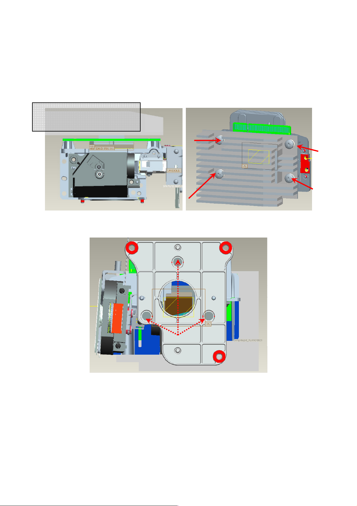
7.4 Assemble Thermal Pad & Gasket Hest-sink then place contact DMD (Fig. 7-4, 7-5).
○
4
i. Press center of Heatsink before assemble spring screws, and then keeps press until
spring screw assembly finish.
i. Pre-fastening Sequence: [ 1 ] - [ 2 ] - [ 3 ] - [ 4 ].
ii. Fastening Sequence: [ 2 ] - [ 1 ] - [ 4 ] - [ 3 ].
iii. Screw Torque must be confirmed to be 6 kg-cm.
Press center of Heatsink when
assemble spring screw
○
1
Fig. 7-4 Fig.7-5
○
3
○
2
7.5 Assemble “Lens Frame” and lock with screws well (Fig. 7-6).
Screw*3
Fig. 7-6
55
Page 56

7.6 Pre-assemble Lens and Pre-Lock with screws. Sequence [1]-[2]-[3]
○
1
7.7 Assemble “Ring Focus”
Ring Focus
○
2
○
3
56
Page 57

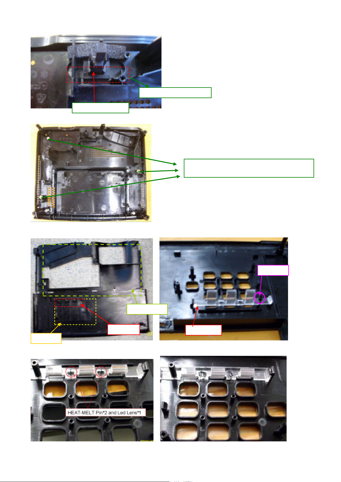
Module Assembly Key Point – Mechanical
1. Appearance Case assembly concern
1.1 Lower Case module
Adjust Foot x1
(Free drop)
Sub_Assy M2.5 Heat melt
nut*3
Sub_Assy M3 Heat melt
Label
Adjust Foot x2
(thread)
Mold in nut*3
Sub_Assy M4 Heat
melt nut*2
nut*2
SATURN Adjust Foot(rear):
SATURN Adjust Foot(raer):
Spring
Add glue on thread
Stand off*2
Push button
foot
57
Page 58
Sponge Align the boss
Sponge adjust
1.2 Upper Case module
M3 Screw
SCRW MACH PH W/FL M3*5L NI
Align Pin
KEYPAD
LED LENS
DOOR LAMP
LED LENS
58
Page 59
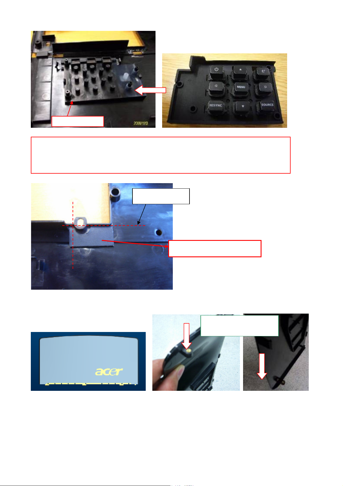
Rubber keypad
Please make sure:
1. Press all rubber close to upper case.
2. After assembled please check rubber surface even.
Align these ribs
1.3 Lamp door module
Mylar for U/C light leakage
M2.5 heat melt nut
direction
59
Page 60

1.4 Front Case and Rear Case module
Front Case
ASSY_SUB:
Heat Melt IR
LENS
Please make
sure IR lens
fixed close to
front case.
ASSY_SUB: IR_board &wire
Please make sure IR board fixed
hook
use M3 screw to fix it
on FC
IR LENS Rear
Please make sure
IR lens fixed close
to rear case.
60
Page 61

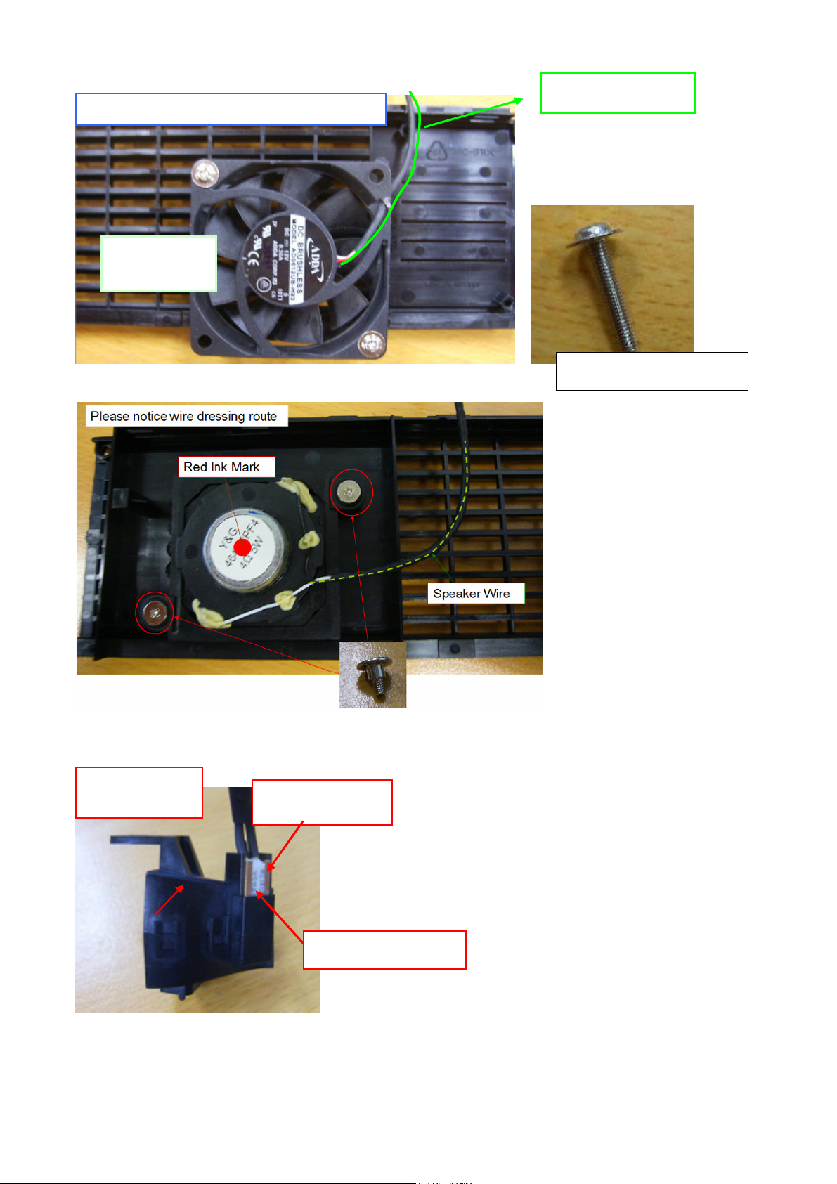
1.5 Inlet Case and Outlet Case module
route
Inlet Case Module
Please notice wire dressing
Align pin on
inlet-case
Notice: The align pin must insert to
fan 6013 completely
61
Page 62
NI
fan wire direction
Inlet Case Module & Fan
FAN60*60*
13
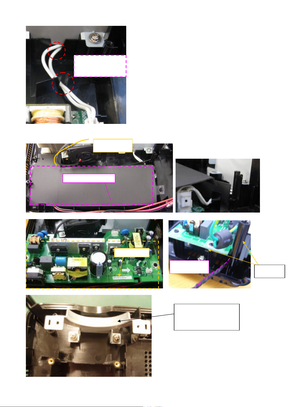
2. Lamp Box & Blower, Power Board assembly concern
Assy_Nozzle
Cu plate: Opening face
outside.
SCRW MACH PH W/FL M3*16L
Thermal breaker-
Text face outside
62
Page 63

SEAT
Screw M3*6L Match
CLIP MOUNT and
MOUNT SEAT
BKT
Nozzle
Blower
CLIP MOUNT and MOUNT
Lamp Box module
Door Switch
Lamp
connector
Louver Lamp Box
Please press to
bottom and check
hook position.
Door Switch
63
Page 64

Align the BKT
Align the BKT
Mylar on
BKT lamp
box
The two pin with heat
shrinkage tube away from
the lamp box
attach tape on lampbox
align the edge first
then align the edge
secend
64
Page 65

3. Ballast wire alignment concern
Ballast
Ballast Mylar EMI
Wire ballast dressing
Notice wire cross dressing
blower
Lamp
box
Wire under the lamp box
65
Page 66
Ballast to lamp
wire addressing
4. Power Board and Main Board wire alignment
Wire Blower
Mylar ballast align pin
Power Board
Wire Ballast
BOSS*2
BKT ST Lens Bottom
66
Page 67
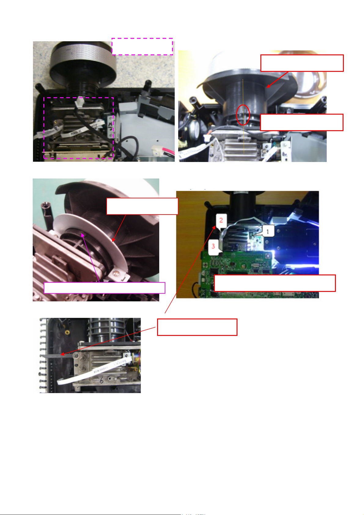
lens
OPTICAL ENG.
Rubber for light leakage on ST
The arrow align the line on ST
lens
BKT ST Lens Top
Notice: The Engine screw Priority
Clip on Eng screw-2
67
Page 68

5. BKT MB & Mylar
Mylar1
Mylar2 Mylar3
Align the edge
cover this surface
cover this surface
Assy the inlet-case before PW-BKT
Notice wire slot
68
Page 69

Wire clip
Wire clip
Here is slot
Notice: The Bkt. Not pressed
the part on power board
Fan 8025
Fan 8025 wire
Grounding
Clip
Fix --Wire Fan8025 & 9225
Fix—Wire speaker
Yellow Green wire goes through here.
69
Page 70

6. MB and Awin BD
STAND OFF M3 D6*9L CU
Fix this screw at first
M3 screw mach
Slot insert
Awin BD
CW wire
Wire dressing
regular and avoid
breaking wire.
Wire saddle
use clip to bind
speaker wire,IR wire, & CW wire
wire Fan6013
70
Page 71

with U/C
Ballast
SHD Main
-
Board At first assemble back side then front side.
Put upper case vertically
directly
wire insert to main-board
This screw fixed
Wire ballast
Rear Case
Upper Case
Push rear cover vertically.
Please check gap.
71
Page 72

attach mylar on UC
Second
align this edge
First
Screw
72
Page 73

Before fixed screw, please check all
hooks.
Notice wire dressing
and don’t interfere
with lamp holder
Film lamp exploded
73
Page 74

7. Overall wire review
Notice: lamp wire dressing.
74
Page 75
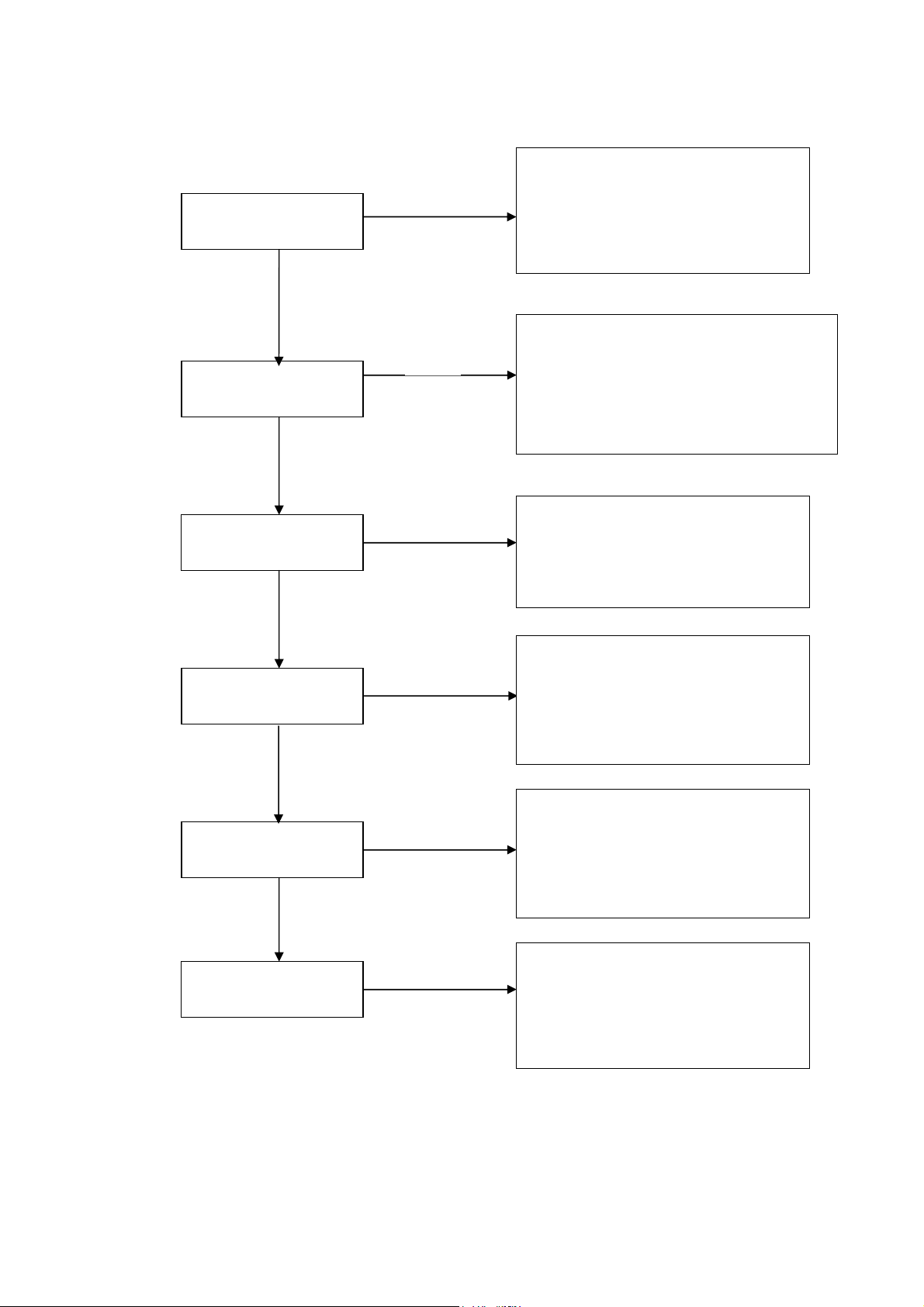
Chapter 4 Troubleshooting
4.
Check Main Board
System Analysis
Keypad LED OK
No
Step:
1. Check Lamp Door
2. Check Power Board and Interlock
3. Check Connection between PWR
BD and Main BD
Yes
1. Check Lampen wire , Lamp wire and
No
If Power On, Lamp
On?
Ballast wire
2. Check C/W and wire connection
3. Check Main board
4. Check Lamp
5. Check Ballast
Yes
Yes
No Signal?
1. Check Input Cable
2. Check OSD Source set up
3. Check Main board
No
Power Auto Turn Off
No
IR Remote Control
NG?
No
Pixel Fail?
Yes
Yes
Yes
1. Check OSD Lamp Hours
2. Check Lamp Door
3. Check Lamp still light or not?
4. Check Fan still spin or not?
5. Check Thermal status
1. Check Remote module battery
2. Check Remote module
3. Check IR Reciver on Main board
4. Check IR Reciver on IR board
1. Check the connection between
Main BD and Chip BD
2. Check the connection between OP
engine and DMD Chip
3. Check Chip board
4. Check Main board
75
Page 76

Optical & Optical Engine Trouble Shooting Guide
No. Item Trouble Shooting Guide
1 Brightness
2 Uniformity
1. Change lamp
1. Change lamp
1. Check ADC calibration
2. Check user’s menu brightness & contrast are default
3 FOFO Contrast
3. Clean DMD
4. Clean PL
5. Check ILL stop assy
1. Clean PL
4 ANSI Contrast
2. Clean DMD
3. Change PL
5 Color
6 Color Uniformity
7 Blue Edge
8 Blue/Purple Border
9 Focus
10 Dust
11
Horizontal/Vertical
Strips
1. Check color wheel delay
2. Check CW 50% point. Replace CW if necessary
1. Change lamp
1. Refer to Item#2-1 (attached below)
2. Change CM
3. Change SUB HSG
1. Refer to Item#2-1(attached below)
2. Change CM
3. Change SUB HSG
1. Change Projection Lens
2. Check parallel between PL datum and DMD
Clean DMD
1. Check connector between chipBD and MainBD
2. Re-install DMD with chipBD
3. Check if any pin of C-Spring is missing, damaged or dirty
4. Change new ChipBD/C-Spring
5. Change new DMD
12 Pixel Fail Change new DMD
2-1. “Blue Edge” Trouble Shooting:
I. Re-adjust “Overfill” first.
For Overfill Re-adjustment:
i. Those 2 Adjustment Screws must be released for around 2 mm first.
ii. Alignment Sequence:
a. To adjust “Horizontal Adjustment Screw” firstly, then “Vertical Adjustment
Screw”.
b. Refer to Figure 2-1..
76
Page 77

(2) Overfill Vertical
Adjustment Screw
(1) Overfill Horizontal
Adjustment Screw
Fig. 2-1
II. Re-assemble LP module—include LP, LP Baffle, LP clip.
DMD Image Quality
1. Scope
This document specifies the image quality requirements applicable to the DLP®.55XGA
Type X, Series 450 Value, and DLP
TM
.65WXGA-800 Value Component Set. The
Component Set provides the DLP®. 55XGA Type X and Series 450 Value Projector with
digital imaging functionality based on Digital Micromirror Device (DMD) technology.
2. Definitions: (Defects and Test Screens)
Blemish
A blemish is an obstruction, reflection, or refraction of light that is visible, but out of focus
in the projected image under specified conditions of inspection (see Table 1). It is caused
by a particle, scratch, or other artifact located in the image illumination path.
Dark pixel
A single pixel or mirror that is stuck in the OFF position and visibly darker than the
surrounding pixels.
Bright pixel
A single pixel or mirror that is stuck in the ON position and visibly brighter than the
surrounding pixels.
Unstable pixel
A single pixel or mirror that does not operate in sequence with parameters loaded into
memory. The unstable pixel appears to be flickering asynchronously with the image.
Adjacent pixel
Two or more stuck pixels sharing a common border or common point, also referred to as
a cluster.
Row or Column Defect
The reset boundary artifact is a single row of pixels on the reset group boundaries that
are visibly darker or lighter than the neighboring rows of pixels.
Pond of Mirrors (POM)
POM is a rectangular array of off-state mirrors surrounding the active area.
Eyecatcher
Eyecatcher's are blemishes appearing in the area outside of the Active Area. These are
due to particles and various DMD window or window aperture “defects”
including: digs, voids, and scratches.
77
Page 78

Border Artifacts
Border artifacts are a general category of image artifacts that may show up on screen in
the area outside of the active array. Border artifacts include: Exposed Bond Wires,
Exposed Metal 2, and Reflective Edge.
Bond Wires
Bond Wires are the electrical connections between the die and the DMD ceramic
package. If visible, they will appear as short light parallel lines outside of the
Pond of Mirrors (POM).
Exposed Metal 2
Exposed Metal 2 is due to a shift in positioning of either the die or the window
aperture, which may allow light to be reflected off of the layer of metal 2 that is below the
super structure (mirrors). This defect is located outside of the POM.
Reflective Edge
Reflective Edge is light that may reflect from the edge of the DMD window aperture onto
the projection screen. It will appear as a thin diffuse line outside of the POM.
Blue 60 Screen
The Blue 60 screen is used to test for major dark blemishes. All areas of the screen are
colored a Microsoft Paintbrush blue 60 (green and red set at 0, blue set at 60). NOTE: If
linear degamma is not used then the Microsoft Paintbrush values must be adjusted to
match the degamma table being used in order to generate an equivalent blue level on the
test screen image.
Gray 10 Screen
The Gray 10 screen is used to test for major light blemishes. All areas of the screen are
colored a Microsoft Paintbrush gray 10 (green, red, and blue set at 10).
NOTE: If linear degamma is not used then the Microsoft Paintbrush values must be
adjusted to match the degamma table being used in order to generate an equivalent gray
level on the test screen image.
Gray 30 Screen
The Gray 30 screen is used to test for the reset boundary artifact. All areas of the screen
are colored a Microsoft Paintbrush gray 30 (green, red, and blue set at 30).
NOTE: If linear degamma is not used then the Microsoft Paintbrush values must be
adjusted to match the degamma table being used in order to generate an equivalent gray
level on the test screen image.
3. ACCEPTANCE REQUIREMENTS
3.1 Conditions of Acceptance
All DMD image quality returns will be evaluated using the following projected image test
conditions:
Test Set degamma shall be linear.
Test Set brightness and contrast settings shall be set to nominal.
The diagonal size of the projected image shall be a minimum of 60 inches.
The projection screen shall be 1X gain.
The projected image shall be inspected from an 8 feet minimum viewing distance.
The image shall be in focus during all Table 1 tests.
3.2 Test Sequence
Tests shall be run in the sequence listed in Table 1.
78
Page 79

Table 1 Image Quality Specification (for S5201/S5201B)
SEQ#
1
Test SCREEN ACCEPTANCE CRITERIA
Major Dark
Blemish
Blue 60
1. 4 visible dark blemishes are allowed in the ≦
active area
2. No blemish will be >1.5” long/diameter
1. 4 visible dark blemishes are allowed in the ≦
active area
2. No blemish will be >1.5” long/diameter
2
Major Light
Blemish
Gray 10
Reset
3
Boundary
Gray 30 No reset boundary artifacts allowed
Artifact
4
5
Eyecatchers /
Border Artifacts
Projected
Images
Any screen Eyecatcher and border artifacts are allowed
1. Any screen
2. Gray 10
3. Any screen
4. Gray 10
5. Whit
6. Any screen
7. Any screen
1. No adjacent pixels
2. No bright pixels in Active Area
3. No unstable Pixels in Active Area
4. 1 right pixel in the POM≦
5. 4 dark pixels in the Active Area≦
6. No DMD window aperture shadowing on the
Active Area
7. Minor blemishes are allowed
Table 2 Image Quality Specification (for S5301WB)
SEQ#
Test SCREEN ACCEPTANCE CRITERIA
1. ≦4 visible dark blemishes are allowed in the
1
Major Dark
Blemish
Blue 60
active area
2. No blemish will be > 1” long/diameter
1. ≦4 visible dark blemishes are allowed in the
2
Major Light
Blemish
Gray 10
active area
2. No blemish will be > 1” long/diameter
Reset
3
Boundary
Gray 30 No reset boundary artifacts allowed
Artifact
4
Eyecatchers /
Border Artifacts
Any screen Eyecatcher and border artifacts are allowed
1. No adjacent pixels
5
Projected
Images
8. Any screen
9. Gray 10
10. Any screen
11. Gray 10
12. Whit
13. Any screen
14. Any screen
2. No bright pixels in Active Area
3. No unstable Pixels in Active Area
4. ≦ 1 right pixel in the POM
5. ≦ 4 dark pixels in the Active Area
6. No DMD window aperture shadowing on the
Active Area
7. Minor blemishes are allowed
Notes:
1. Projected blemish numbers include the count for the shadow of the window artifact in
addition to the artifact itself.
2. During all Table 1 tests, projected images shall be inspected in accordance with the
79
Page 80

conditions of inspection specified in Section 3.
3. The rejection basis for all cosmetic DMD defects (scratches, nicks, particles) will be the
projected image tests referenced in Table 1.
4. Devices that meet this image quality specification but are deemed undesirable by the
customer may not be returned to TI without prior approval by TI.
5. Screens < Gray 10 shall not be used as a basis for rejecting a DMD for image quality.
80
Page 81

Power Supply Trouble Shooting Guide
1. Introduction
This document is prepared to be a guide to repair trouble sets, some problems
happen more frequently are taken as example in it.
2. Problems
(a) no power
No power
Check power
Is CN701 pin11 =5v?
No
Is door SW press down?
No
Check lamp door
Yes
Yes
Change main BD
Change power BD
81
Page 82

(b)lamp can not turned on
Yes
Yes
Yes
Lamp can not turned on
has lamp wire connect
correct? (Ballast bd
between lamp)
has power wire connect
correct? (power bd
between ballast bd)
No
Wire connect certainty
No
Wire connect certainty
has enable wire connect
correct? (main bd to
ballast bd)
A
No
Wire connect certainty
82
Page 83

A
Has TH breaker wire connect
correct? (main bd to ballast bd)
Yes
Has color wheel operation normally?
Yes
If change ballast bd, lamp can be
Turned on or not?
No
Wire connect certainty
No
Change color wheel
No
Change lamp
Yes
Change ballast bd
83
Page 84

LED Messages Definition
Power_LED Power_LED Lamp_LED Temp_LED
Blue Red Red Red
Power Plug
Standby -- ON -- --
Power button ON ON -- -- --
Lamp retry
Cooling state --
Power button OFF:
Cooling completed;
Standby Mode
Firmware Download ON ON -- -Thermal sensor
error (T2≧85℃)
(Lamp Over
Temperature) OSD
shows “Projector
Overheated”
Thermal sensor
error (T1
OSD shows
“Projector
Overheated”
Fan lock error OSD
shows red “Fan
Fail, Will
automatically turn
off soon”
Lamp error (Lamp,
ballast)
Color Wheel fail ON --
≧40℃
-
-
0.5 second H(On),
0.5 second L(Off)
flashing
-- ON -- --
ON -- -- ON
)
ON -- -- ON
ON -- --
ON -- ON --
Flash ON to OFF Flash ON to OFF Flash ON to OFF
-- -- --
0.5 second H(ON),
0.5 second L(OFF)
flashing
-- --
0.5 second H(ON),
0.5 second L(OFF)
flashing
0.5 second H(On),
0.5 second L(Off)
flashing
--
84
Page 85

Error Count Messages Definition
Error Count Definition Specification
LAMP Fail error
FAN 1 Speed Error
FAN 2 Speed Error
FAN 3 Speed Error
FAN 4 Speed Error
Sensor 1 Open Error
Sensor 1 Short Error
Temperature 1 Error
FANIC 1 I2C ERROR
LAMP OFF DETECT LAMPLIT
LAMP FAN SPEED ERROR SPEED OVER ± 20%
POWER FAN SPEED ERROR SPEED OVER ± 20%
BLOWER FAN SPEED
ERROR
DMD FAN SPEED ERROR SPEED OVER ± 20%
Main Board SENSOR ERROR DETECT Sensor 1
Main Board SENSOR ERROR DETECT Sensor 1
over limited temperature DETECT Sensor 1
I2C communication error DETECT Fan IC
SPEED OVER ± 20%
85
Page 86

RS232 Connection
1. Connection:
The illustration of connection between PC and Projector is shown below.
<CAUTION>
Make sure that your computer and projector are turned off before connection.
Power on the computer first, and then plug the power cord of the projector. (It may
cause Com port incorrect function, if you do not follow this instruction)
Adapters may be necessary depending on the PC connected to this projector. Please
contact with your dealer for further details.
2. Hardware connection
<Download cable>
<Pin assignment for this two end>
<Interface Settings>
RS-232 protocol
Baud Rate 9600 bps
Data Length 8 bit
Parity Check None
Stop Bit 1 bit
Flow Control None
Command Category
Refer to Appendix A
86
Page 87

Adjustment / Alignment Procedure
Content :
1. Color Wheel Delay Alignment
2. Overfill adjustment
3. PC Alignment Procedure
87
Page 88

1. Color Wheel Delay Alignment
Procedure:
1. Enter Factory Mode
2. Enter Block 1
3. Change CW Delay by adjusting the following gray pattern to smooth
32 Gray pattern
2. Overfill adjustment
1. “Full White Pattern” is suggested for this alignment.
2. Adjust 2 LP-alignment Screws (upper side / lower front side of Optical Engine) behind
Color Wheel.
3. Alignment Criteria is to adjust these 2 screws until “No Dark Edges” and “No
Shadows” can be observed in image.
88
Page 89

3. PC Alignment Procedure
Item
Value
Cal R Offset
512
Cal G Offset
512
Cal B Offset
512
Cal R Gain
637
Cal G Gain
637
Cal B Gain
637
YPbPr R Offset
512
YPbPr B Offset
512
Equipment:
- Pattern generator (Chroma-2337)
OSD Default value:
Procedure:
Gray Level:
1. Connect power, D-sub, into projector.
2. Change Timing and pattern of pattern generator:
3. Timing: 1024*768 @60Hz (XGA)
4. Pattern: As Figure1 {A near white color (240,240,240) and a near black
color(16,16,16)}
5. Light on projector
6. Set user OSD values to default.
7. Enter factory mode.
8. Set Factory values to default.
9. Press “Calibration RGB” to let the black level to just distinguish, and the light output
of white level to just max.
10. Check the 32 levels of gray. All steps must appear.
11. Calibrate Dsub_1 only .( Dsub_2 follows Dsub_1 )
White-black pattern
89
Page 90
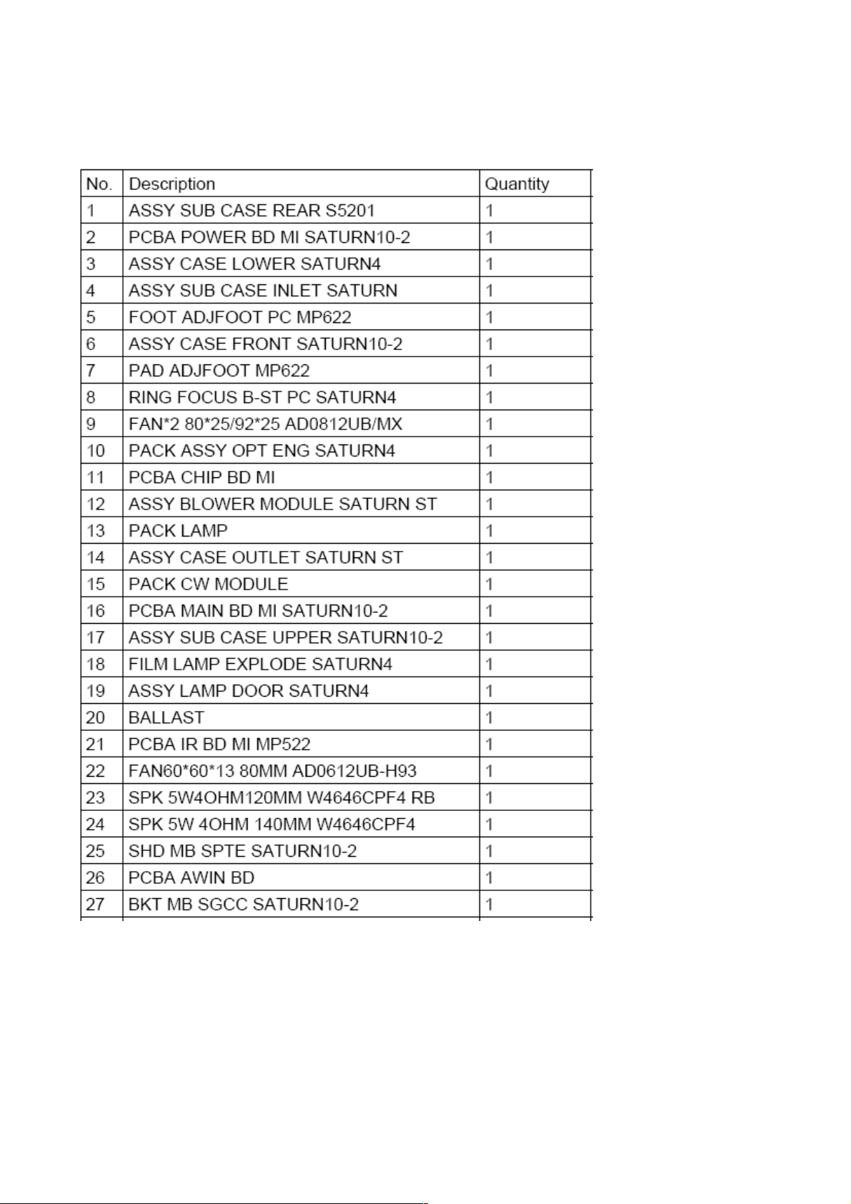
Chapter 5 FRU List
Exploded Diagram
Module 1 – Total Exploded View
90
Page 91

91
Page 92

Module 2 – ASSY UPPER CASE
92
Page 93

Module 3 – ASSY LOWER CASE
93
Page 94
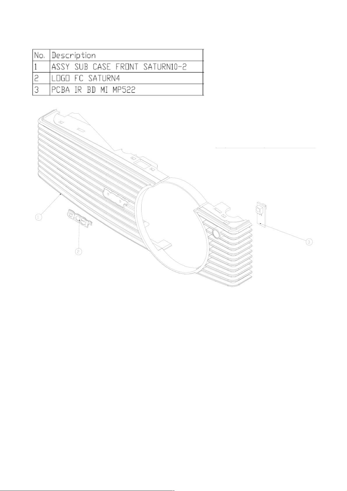
Module 4 – ASSY FRONT CASE
94
Page 95
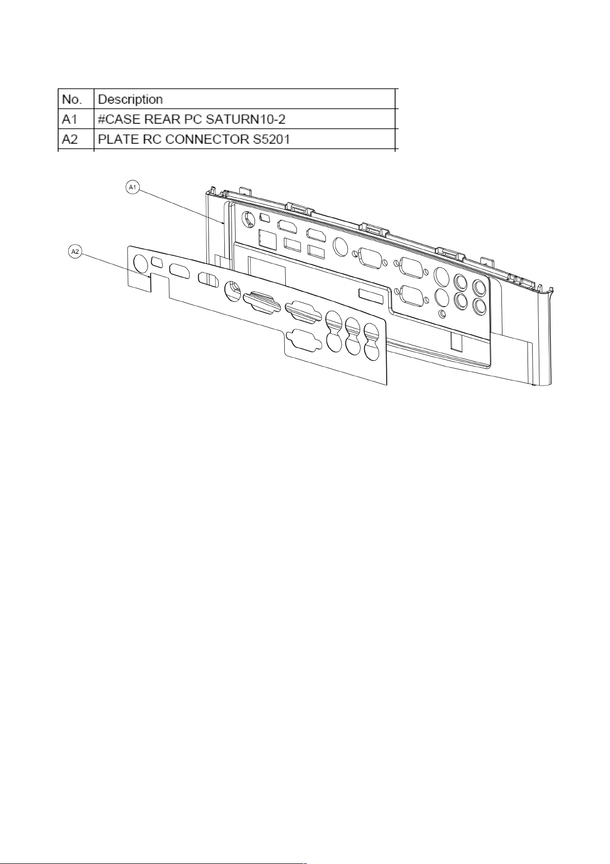
Module 5 – ASSY REAR CASE
95
Page 96

FRU List
Acer R3 Remote
VZ.JBG00.001
Model CATEGORY PARTNAME
S5201/S5201B/
S5301WB
ACCESSORY
Control Acer
Rmote R3 with
Laser
ACER PART
NO.
Photo
S5201/S5201B/
S5301WB
S5201/S5201B/
S5301WB
S5201/S5201B/
S5301WB
BOARD
BOARD
BOARD
DMD CHIP
BOARD
IR SENSOR
BOARD
TOOL KIT FOR
EDID UPLOAD
55.JBG0Q.003
55.J900Q.005
6K.J900Q.001
S5201 BOARD MAIN BOARD 55.JC90Q.001
S5201B BOARD MAIN BOARD 55.JCB0Q.001
S5301WB BOARD MAIN BOARD 55.JCD0Q.001
S5201/S5201B/
S5301WB
S5201/S5201B/
S5301WB
BOARD BALLAST 55.JC20Q.002
BOARD
POWER
BOARD
55.JC90Q.002
EXTEND
S5201 BOARD
BOARD (WITH
55.JC90Q.003
LAN CONN.)
96
Page 97

S5201B BOARD
EXTEND
BOARD (WITH
USB/LAN
CONN.)
55.JCB0Q.002
S5301WB BOARD
S5201/S5201B/
S5301WB
S5201/S5201B/
S5301WB
S5201/S5201B/
S5301WB
S5201/S5201B/
S5301WB
S5201/S5201B/
S5301WB
CABLE
CABLE
CABLE
CABLE D-SUB CABLE 50.J900Q.001
CABLE RCA CABLE 50.J900Q.002
EXTEND
BOARD (WITH
USB/LAN
CONN.)
POWER CORD
EUR
POWER CORD
UK
POWER CORD
SWIS
55.JCD0Q.002
27.LBJ0Q.001
27.LDW0Q.001
50.LE20Q.004
S5201/S5201B/
S5301WB
S5201/S5201B/
S5301WB
S5201/S5201B/
S5301WB
S5201/S5201B/
S5301WB
S5201/S5201B/
S5301WB
CABLE
CABLE
CABLE
CABLE
CABLE
CABLEBALLAST TO
LAMP
CABLE- M/B TO
BALLAST
CABLE- M/B TO
IR BOARD
CABLE- LAMP
DOOR SWITCH
CABLEPOWER
BOARD TO
BALLAST
50.JBG0Q.002
50.K140Q.004
50.K140Q.001
50.K140Q.005
50.JBG0Q.003
97
Page 98

S5201/S5201B/
S5301WB
S5201/S5201B/
S5301WB
CASE/COVE
R/BRACKET
ASSEMBLY
CASE/COVE
R/BRACKET
ASSEMBLY
INTEL CASE 60.K140Q.002
OUTLET CASE 60.K140Q.003
S5201/S5201B/
S5301WB
S5201/S5201B/
S5301WB
S5201/S5201B/
S5301WB
S5201/S5201B/
S5301WB
S5201/S5201B/
S5301WB
CASE/COVE
R/BRACKET
ASSEMBLY
CASE/COVE
R/BRACKET
ASSEMBLY
CASE/COVE
R/BRACKET
ASSEMBLY
CASE/COVE
R/BRACKET
ASSEMBLY
CASE/COVE
R/BRACKET
ASSEMBLY
FRONT CASE
(W/O IR
BOARD)
60.K140Q.009
SATURN10-2
FOCUS RING 60.K140Q.007
LAMP DOOR 60.K140Q.008
UPPER CASE
(W/ KEYPAD
RUBBER&
60.JBG0Q.002
BRACKET)
LOWER CASE
(W/ ADJUST
60.K140Q.005
FOOT)
S5201
S5201B/S5301
WB
S5201/S5201B
S5301WB
CASE/COVE
R/BRACKET
ASSEMBLY
CASE/COVE
R/BRACKET
ASSEMBLY
DIGITAL
LIGHT
DEVICE
DIGITAL
LIGHT
DEVICE
REAR CASE 60.JC90Q.001
REAR CASE 60.JBG0Q.001
LIGHT PIPE 57.JBJ0Q.002
LIGHT PIPE
MODULE
57.JC80Q.002
98
Page 99

S5201/S5201B
COLOR WHEEL
Lamp Module for
COLOR WHEEL
S5301WB
DIGITAL
LIGHT
DEVICE
DIGITAL
LIGHT
DEVICE
LENS 57.K140Q.002
LENS 57.JC80Q.003
S5201/S5201B
S5301WB
S5201/S5201B
S5301WB
S5201/S5201B
DIGITAL
LIGHT
DEVICE
DIGITAL
LIGHT
DEVICE
DIGITAL
LIGHT
DEVICE
DIGITAL
LIGHT
DEVICE
DIGITAL
LIGHT
DEVICE
DMD CHIP 57.K110Q.001
DMD CHIP 57.JC80Q.004
MODULE(W/
SENSOR BD &
EC.JC900.001
CABLE)
S5301WB
EC.JC900.001
Philips 230W
Lamp Module 57.JC90Q.001
S5301WB
S5201/S5201B
S5301WB
S5201/S5201B/
S5301WB
DIGITAL
LIGHT
DEVICE
DIGITAL
LIGHT
DEVICE
DIGITAL
LIGHT
DEVICE
MODULE(W/
SENSOR BD &
CABLE)
ENGINE
MODULE
ENGINE
MODULE
57.JCD0Q.001
57.JBG0Q.002
57.JC80Q.005
FAN FAN (X2) 23.K140Q.001
99
Page 100
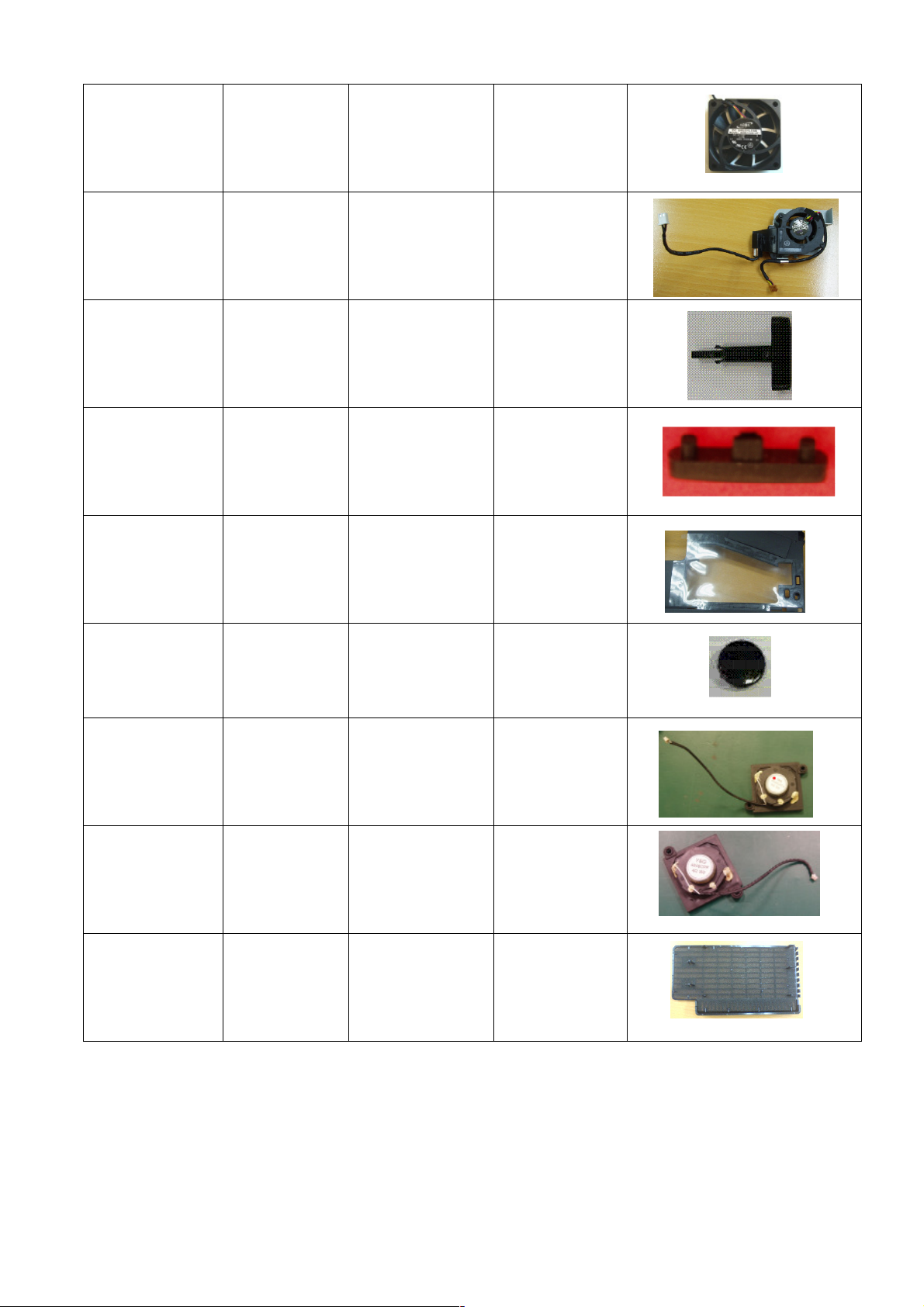
Others_Projector
S5201/S5201B/
S5301WB
S5201/S5201B/
S5301WB
S5201/S5201B/
S5301WB
S5201/S5201B/
S5301WB
S5201/S5201B/
S5301WB
FAN
FAN
MISCELLANE
OUS
MISCELLANE
OUS
MISCELLANE
OUS
FAN (60*60*13
53MM)
FAN BLOWER
MODULE
FOOT
ADJFOOT
RUBBER
ADJFOOT PAD
FILM LAMP
EXPLODE
SATURN4
23.K140Q.006
23.JC90Q.001
47.J900Q.001
47.K140Q.001
47.K140Q.002
S5201/S5201B/
S5301WB
S5201/S5201B/
S5301WB
S5201/S5201B/
S5301WB
MISCELLANE
OUS
SPEAKER
SPEAKER
LENS IR REAR 47.JBG0Q.001
SPEAKER
140MM
SPEAKER
120MM
23.K140Q.003
23.K140Q.004
Qisda Dust filter
S5201/S5201B/
S5301WB
MISCELLANE
OUS
P5205&S5200
Qisda Dust filter
JZ.K1300.001
for China sku
(Note) The updated P/N refers to latest Spare Part List
100
 Loading...