

Page 1

Aspire S3 MS2346
SERVICEGUIDE
Page 2

Revision History
Refer to the table below for the updates made to this Aspire S3 MS 2346 S er vice Guid e .
Date Chapter Updates
Service guide files and updates are available on the ACER/CSD website. For more
information, go to http://csd.acer.com.tw
without notice.
.The information in this guide is subject to change
Disclaimer
The information in this guide is subject to change without notice.
There are no representations or warranties, either expressed or implied, with respect to the
contents hereof and specifically disclaims any warranties of merchantability or fitness for any
particular purpose. The software described in this manual is sold or licensed "as is". Should
the programs prove defective following their purc h as e, the bu ye r (n ot the ma n uf ac tur e r,
distributor, or its dealer) assumes the entire cost of all necessary servicing, repair, and any
incidental or consequential damages resulting from any defect in the software.
Copyright
© 2011 by Acer Incorporated. All rights reserved. No part of this publication may be
reproduced, transmitted, transcribed, stored in a retrieval system, or translated into any
language or computer language, in any form or by any means, electronic, mechanical,
magnetic, optical, chemical, manual or otherwise, without the prior written permission of Acer
Incorporated.
HDMI, the HDMI logo, and High Definition Multimedia Interface are trademarks or registered
trademarks of HDMI Licensing, LLC in the United St ates and other countries.
ii
Page 3

Conventions
WARNING:
!
CAUTION:
!
IMPORTANT:
+
The following conventions are used in this manual:
Indicates a potential for personal injury.
Indicates a potential loss of data or damage to equipment.
Indicates information that is important to know for the proper completion of a
procedure, choice of an option, or completing a task.
The following typographical conventions are used in this document:
Book titles, directory names, file names, path names, and program/process names are
shown in italics.
Example:
the DRS5 User's Guide
/usr/local/bin/fd
the /TPH15spool_M program
Computer output (text that represents information displayed on a computer screen,
such as menus, prompts, responses to input, and error messages) are shown in
constant width.
Example:
[01] The server has been stopped
User input (text that represents information entered by a computer user, such as
command names, option letters, and words) are shown in constant width bold.
Variables contained within user input are shown in angle brackets (< >).
Example:
At the prompt, type run <file name> -m
Keyboard keys are shown in bold italics.
Example:
After entering data, press Enter.
iii
Page 4

General information 0
Before using this information and the product it supports, read the following general
information.
This service guide provides you with all technical information relating to the basic
configuration for Acer’s global product offering. To better fit local market requirements and
enhance product competitiveness, your regional office may have decided to extend the
functionality of a machine (such as add-on cards, modems, or extra memory capabilities).
These localized features are not covered in this generic service guide. In such cases, contact
your regional office or the responsible pe rsonnel/channe l to provide yo u with further techn ical
details.
When ordering FRU parts: Check the most up-to-date information available on your regional
Web or channel. If, for whatever reason, a part number change is made, it may not be noted
in this printed service guide.
Acer-authorized Service Providers: Your Acer office may have a different part number code
than those given in the FRU list in this service guide. You must use the list provided by your
regional Acer office to order FRU parts for repair and service of customer machines.
iv
Page 5

Aspire S3 MS2346
CHAPTER 1
Hardware Specifications
Features. . . . . . . . . . . . . . . . . . . . . . . . . . . . . . . . . . . . . . . . . . . . .1-3
Operating System . . . . . . . . . . . . . . . . . . . . . . . . . . . . . . . . . . .1-3
Platform . . . . . . . . . . . . . . . . . . . . . . . . . . . . . . . . . . . . . . . . . . .1-3
System Memory. . . . . . . . . . . . . . . . . . . . . . . . . . . . . . . . . . . . .1-3
Display. . . . . . . . . . . . . . . . . . . . . . . . . . . . . . . . . . . . . . . . . . . .1-3
Graphics . . . . . . . . . . . . . . . . . . . . . . . . . . . . . . . . . . . . . . . . . .1-3
Storage Subsystem . . . . . . . . . . . . . . . . . . . . . . . . . . . . . . . . . .1-4
Audio Subsystem. . . . . . . . . . . . . . . . . . . . . . . . . . . . . . . . . . . .1-4
Communication . . . . . . . . . . . . . . . . . . . . . . . . . . . . . . . . . . . . .1-4
Privacy Control . . . . . . . . . . . . . . . . . . . . . . . . . . . . . . . . . . . . .1-4
Power Adapter and Battery . . . . . . . . . . . . . . . . . . . . . . . . . . . .1-5
Keyboard and Pointing Device . . . . . . . . . . . . . . . . . . . . . . . . .1-5
I/O Ports. . . . . . . . . . . . . . . . . . . . . . . . . . . . . . . . . . . . . . . . . . .1-5
Software and Tools . . . . . . . . . . . . . . . . . . . . . . . . . . . . . . . . . .1-6
Warranty . . . . . . . . . . . . . . . . . . . . . . . . . . . . . . . . . . . . . . . . . .1-7
Dimensions and Weight. . . . . . . . . . . . . . . . . . . . . . . . . . . . . . .1-7
Environment. . . . . . . . . . . . . . . . . . . . . . . . . . . . . . . . . . . . . . . .1-7
Notebook Tour. . . . . . . . . . . . . . . . . . . . . . . . . . . . . . . . . . . . . . . .1-8
Open Front View . . . . . . . . . . . . . . . . . . . . . . . . . . . . . . . . . . . .1-8
Rear View . . . . . . . . . . . . . . . . . . . . . . . . . . . . . . . . . . . . . . . . .1-9
Left View . . . . . . . . . . . . . . . . . . . . . . . . . . . . . . . . . . . . . . . . . .1-10
Right View . . . . . . . . . . . . . . . . . . . . . . . . . . . . . . . . . . . . . . . . .1-11
Base View . . . . . . . . . . . . . . . . . . . . . . . . . . . . . . . . . . . . . . . . .1-12
Touchpad Basics. . . . . . . . . . . . . . . . . . . . . . . . . . . . . . . . . . . .1-13
Keyboard . . . . . . . . . . . . . . . . . . . . . . . . . . . . . . . . . . . . . . . . . .1-14
D2D Recovery . . . . . . . . . . . . . . . . . . . . . . . . . . . . . . . . . . . . . .1-18
System Block Diagram . . . . . . . . . . . . . . . . . . . . . . . . . . . . . . .1-18
Specification Tables . . . . . . . . . . . . . . . . . . . . . . . . . . . . . . . . . . .1-19
CHAPTER 2
System Utilities
BIOS Setup Utility . . . . . . . . . . . . . . . . . . . . . . . . . . . . . . . . . . . . .2-3
Navigating the BIOS Utility . . . . . . . . . . . . . . . . . . . . . . . . . . . .2-3
BIOS Menus . . . . . . . . . . . . . . . . . . . . . . . . . . . . . . . . . . . . . . .2-4
v
Page 6

BIOS Flash Utilities. . . . . . . . . . . . . . . . . . . . . . . . . . . . . . . . . . . .2-12
DOS Flash Utility . . . . . . . . . . . . . . . . . . . . . . . . . . . . . . . . . . . .2-13
WinFlash Utility . . . . . . . . . . . . . . . . . . . . . . . . . . . . . . . . . . . . .2-13
Remove HDD/BIOS Password Utilities . . . . . . . . . . . . . . . . . . . .2-14
Removing the HDD Password. . . . . . . . . . . . . . . . . . . . . . . . . .2-14
Removing the BIOS Passwords . . . . . . . . . . . . . . . . . . . . . . . .2-15
Using DMI Tools . . . . . . . . . . . . . . . . . . . . . . . . . . . . . . . . . . . . . .2-16
LAN EEPROM Utility . . . . . . . . . . . . . . . . . . . . . . . . . . . . . . . . .2-16
CHAPTER 3
Machine Maintenance
Machine Disassembly and Replacement . . . . . . . . . . . . . . . . . .3-5
Recommended Equipment . . . . . . . . . . . . . . . . . . . . . . . . . . . .3-5
Replacement Requirements . . . . . . . . . . . . . . . . . . . . . . . . . . .3-5
Pre-disassembly Instructions. . . . . . . . . . . . . . . . . . . . . . . . . . .3-6
Disassembly Process. . . . . . . . . . . . . . . . . . . . . . . . . . . . . . . . . .3-7
Removing the Lower Case . . . . . . . . . . . . . . . . . . . . . . . . . . . .3-9
Removing the Battery Pack. . . . . . . . . . . . . . . . . . . . . . . . . . . .3-10
Removing the Left and Right Speakers. . . . . . . . . . . . . . . . . . .3-13
Removing the WLAN Module . . . . . . . . . . . . . . . . . . . . . . . . . .3-15
Removing the DC-In Module (WLAN Board). . . . . . . . . . . . . . .3-17
Removing the DC-In Module (M-SATA Board) . . . . . . . . . . . . .3-18
Removing the HDD Module. . . . . . . . . . . . . . . . . . . . . . . . . . . .3-19
Removing the SSD Module . . . . . . . . . . . . . . . . . . . . . . . . . . . .3-22
Removing the Card Reader Board . . . . . . . . . . . . . . . . . . . . . .3-25
Removing the Mainboard. . . . . . . . . . . . . . . . . . . . . . . . . . . . . .3-27
Removing the Thermal Module . . . . . . . . . . . . . . . . . . . . . . . . .3-31
Removing the RTC Battery . . . . . . . . . . . . . . . . . . . . . . . . . . . .3-33
Removing the WLAN Board. . . . . . . . . . . . . . . . . . . . . . . . . . . .3-34
Removing the M-SATA Board . . . . . . . . . . . . . . . . . . . . . . . . . .3-35
Removing the Keyboard . . . . . . . . . . . . . . . . . . . . . . . . . . . . . .3-36
Removing the Power Button Board . . . . . . . . . . . . . . . . . . . . . .3-38
Removing the Middle Cover Assembly . . . . . . . . . . . . . . . . . . .3-39
Removing the LCD Module . . . . . . . . . . . . . . . . . . . . . . . . . . . .3-41
Reassembly Process . . . . . . . . . . . . . . . . . . . . . . . . . . . . . . . . . .3-43
Replacing the LCD Module . . . . . . . . . . . . . . . . . . . . . . . . . . . .3-43
Replacing the Middle Cover Assembly . . . . . . . . . . . . . . . . . . .3-45
Replacing the Power Button Board . . . . . . . . . . . . . . . . . . . . . .3-47
Replacing the Keyboard . . . . . . . . . . . . . . . . . . . . . . . . . . . . . .3-48
vi
Page 7

Replacing the WLAN Board. . . . . . . . . . . . . . . . . . . . . . . . . . . .3-50
Replacing the M-SATA Board.. . . . . . . . . . . . . . . . . . . . . . . . . .3-51
Replacing the RTC Battery . . . . . . . . . . . . . . . . . . . . . . . . . . . .3-52
Replacing the Thermal Module . . . . . . . . . . . . . . . . . . . . . . . . .3-53
Replacing the Mainboard. . . . . . . . . . . . . . . . . . . . . . . . . . . . . .3-55
Replacing the Card Reader Board. . . . . . . . . . . . . . . . . . . . . . .3-59
Replacing the HDD Module. . . . . . . . . . . . . . . . . . . . . . . . . . . .3-61
Replacing the SSD Module . . . . . . . . . . . . . . . . . . . . . . . . . . . .3-64
Replacing the DC-In Module (WLAN Board). . . . . . . . . . . . . . .3-67
Replacing the DC-In Module (M-SATA Board) . . . . . . . . . . . . .3-68
Replacing the WLAN Module. . . . . . . . . . . . . . . . . . . . . . . . . . .3-69
Replacing the Right Speakers. . . . . . . . . . . . . . . . . . . . . . . . . .3-71
Replacing the Battery Pack . . . . . . . . . . . . . . . . . . . . . . . . . . . .3-73
Replacing the Lower Case. . . . . . . . . . . . . . . . . . . . . . . . . . . . .3-76
CHAPTER 4
Troubleshooting
Introduction. . . . . . . . . . . . . . . . . . . . . . . . . . . . . . . . . . . . . . . . . .4-3
General Information . . . . . . . . . . . . . . . . . . . . . . . . . . . . . . . . . . .4-3
Power On Issues . . . . . . . . . . . . . . . . . . . . . . . . . . . . . . . . . . . .4-4
No Display Issues . . . . . . . . . . . . . . . . . . . . . . . . . . . . . . . . . . .4-5
LCD Failure . . . . . . . . . . . . . . . . . . . . . . . . . . . . . . . . . . . . . . . .4-7
Keyboard Failure . . . . . . . . . . . . . . . . . . . . . . . . . . . . . . . . . . . .4-8
Touchpad Failure. . . . . . . . . . . . . . . . . . . . . . . . . . . . . . . . . . . .4-9
Internal Speaker Failure . . . . . . . . . . . . . . . . . . . . . . . . . . . . . .4-10
Microphone Failure . . . . . . . . . . . . . . . . . . . . . . . . . . . . . . . . . .4-12
USB Failure . . . . . . . . . . . . . . . . . . . . . . . . . . . . . . . . . . . . . . . .4-13
WLAN Failure . . . . . . . . . . . . . . . . . . . . . . . . . . . . . . . . . . . . . .4-14
Card Reader Failure . . . . . . . . . . . . . . . . . . . . . . . . . . . . . . . . .4-15
Thermal Unit Failure . . . . . . . . . . . . . . . . . . . . . . . . . . . . . . . . .4-16
Other Functions Failure. . . . . . . . . . . . . . . . . . . . . . . . . . . . . . .4-17
Intermittent Problems. . . . . . . . . . . . . . . . . . . . . . . . . . . . . . . . . .4-18
Undetermined Problems. . . . . . . . . . . . . . . . . . . . . . . . . . . . . . . .4-18
Error Codes . . . . . . . . . . . . . . . . . . . . . . . . . . . . . . . . . . . . . . . . . .4-19
BIOS Beep Codes . . . . . . . . . . . . . . . . . . . . . . . . . . . . . . . . . . . . .4-20
POST Codes . . . . . . . . . . . . . . . . . . . . . . . . . . . . . . . . . . . . . . . . .4-25
Component Codes. . . . . . . . . . . . . . . . . . . . . . . . . . . . . . . . . . .4-25
Progress Codes. . . . . . . . . . . . . . . . . . . . . . . . . . . . . . . . . . . . .4-29
vii
Page 8

CHAPTER 5
Jumper and Connector Locations
Mainboard Layout. . . . . . . . . . . . . . . . . . . . . . . . . . . . . . . . . . . . .5-3
Clearing Password Check and BIOS Recovery . . . . . . . . . . . . .5-5
Clearing the BIOS Passwords. . . . . . . . . . . . . . . . . . . . . . . . . .5-5
Performing a BIOS Recovery . . . . . . . . . . . . . . . . . . . . . . . . . .5-6
CHAPTER 6
FRU List
Aspire S3 MS2346 Exploded Diagrams. . . . . . . . . . . . . . . . . . . .6-4
Main Assembly . . . . . . . . . . . . . . . . . . . . . . . . . . . . . . . . . . . . .6-4
FRU List . . . . . . . . . . . . . . . . . . . . . . . . . . . . . . . . . . . . . . . . . . . . .6-6
CHAPTER 7
Test Compatible Components
Microsoft Windows 7 Environment Test. . . . . . . . . . . . . . . . . . .7-3
CHAPTER 8
Online Support Information
Online Support Information . . . . . . . . . . . . . . . . . . . . . . . . . . . . .8-3
viii
Page 9

CHAPTER 1
Hardware Specifications
Page 10

Features. . . . . . . . . . . . . . . . . . . . . . . . . . . . . . . . . . . . . . . . . . . . .1-5
Operating System . . . . . . . . . . . . . . . . . . . . . . . . . . . . . . . . . . .1-5
Platform . . . . . . . . . . . . . . . . . . . . . . . . . . . . . . . . . . . . . . . . . . .1-5
System Memory. . . . . . . . . . . . . . . . . . . . . . . . . . . . . . . . . . . . .1-5
Display. . . . . . . . . . . . . . . . . . . . . . . . . . . . . . . . . . . . . . . . . . . .1-5
Graphics . . . . . . . . . . . . . . . . . . . . . . . . . . . . . . . . . . . . . . . . . .1-5
Storage Subsystem . . . . . . . . . . . . . . . . . . . . . . . . . . . . . . . . . .1-6
Audio Subsystem. . . . . . . . . . . . . . . . . . . . . . . . . . . . . . . . . . . .1-6
Communication . . . . . . . . . . . . . . . . . . . . . . . . . . . . . . . . . . . . .1-6
Privacy Control . . . . . . . . . . . . . . . . . . . . . . . . . . . . . . . . . . . . .1-6
Power Adapter and Battery . . . . . . . . . . . . . . . . . . . . . . . . . . . .1-7
Keyboard and Pointing Device . . . . . . . . . . . . . . . . . . . . . . . . .1-7
I/O Ports. . . . . . . . . . . . . . . . . . . . . . . . . . . . . . . . . . . . . . . . . . .1-7
Software and Tools . . . . . . . . . . . . . . . . . . . . . . . . . . . . . . . . . .1-8
Warranty . . . . . . . . . . . . . . . . . . . . . . . . . . . . . . . . . . . . . . . . . .1-9
Dimensions and Weight. . . . . . . . . . . . . . . . . . . . . . . . . . . . . . .1-9
Environment. . . . . . . . . . . . . . . . . . . . . . . . . . . . . . . . . . . . . . . .1-9
Notebook Tour. . . . . . . . . . . . . . . . . . . . . . . . . . . . . . . . . . . . . . . .1-10
Open Front View . . . . . . . . . . . . . . . . . . . . . . . . . . . . . . . . . . . .1-10
Rear View . . . . . . . . . . . . . . . . . . . . . . . . . . . . . . . . . . . . . . . . .1-11
Left View . . . . . . . . . . . . . . . . . . . . . . . . . . . . . . . . . . . . . . . . . .1-12
Right View . . . . . . . . . . . . . . . . . . . . . . . . . . . . . . . . . . . . . . . . .1-13
Base View . . . . . . . . . . . . . . . . . . . . . . . . . . . . . . . . . . . . . . . . .1-14
Touchpad Basics. . . . . . . . . . . . . . . . . . . . . . . . . . . . . . . . . . . .1-15
Keyboard . . . . . . . . . . . . . . . . . . . . . . . . . . . . . . . . . . . . . . . . . .1-16
D2D Recovery . . . . . . . . . . . . . . . . . . . . . . . . . . . . . . . . . . . . . .1-20
System Block Diagram . . . . . . . . . . . . . . . . . . . . . . . . . . . . . . .1-20
1-2
Specification Tables . . . . . . . . . . . . . . . . . . . . . . . . . . . . . . . . . . .1-21
Page 11

Hardware Specifications and Configurations
Features 0
The following is a summary of the computer’s many features.
Operating System 0
Genuine Windows
Genuine Windows
®
7 Home Premium 64-bit
®
7 Home Basic 64-bit
Platform 0
Huron River platform
Supports the Second Generation Intel® Core™ Mobile Processor (Sandy Bridge)
Chipset: Mobile Intel
®
HM77 (6MB BIOS ROM) Chipset
System Memory 0
On board, up to 8pcs DDRIIIL (4GB)
Display 0
13.3-inch High Definition WXGA LED LCD
1366×768 resolution, 16:9 aspect ratio
16.7 million colors, 200-nit brightness
Graphics 0
Graphics controller:
Intel
Dual independent display support
Internal resolutions and refresh rate supported:
800×600, 60 Hz
1024×768, 60 Hz
1280×720, 60 Hz
1280×768, 60 Hz
1360×768, 60 Hz
1366×768, 60 Hz
Maximum Resolution HDMI: 1920x1080: 60Hz
Hardware Specifications and Configurations 1-3
®
HD Graphics 3000 with 128 MB of dedicated system memory, supporting
®
Microsoft
DirectX® 10.1
Page 12

Storage Subsystem 0
Hard disk drive 0
2.5-inch, 9.5 mm, 5400 rpm SATA hard disk drive (HDD) or
2.5-inch, 9.5 mm, Flash Disk SATA solid state drive (SSD)
Card reader 0
2-in-1 card reader slot
Supports MultiMediaCard™ (MMC), MultiMediaCard Plus (MMCplus™) and Secure
Digital™ (SD) cards
Audio Subsystem 0
Built-in microphone
Two 1W, built-in speakers
Headphone and microphone combo jack
Realtek 271X VB3
Communication 0
Webcam 0
1.3 MP HD webcam
Acer Video Conference software, featuring:
Acer Crystal Eye webcam with 1280×1024 resolution
Acer Video Conference Manager featuring Video Quality Enhancement (VQE)
technology
Supports 720p HD audio/video recording
Wireless and networking 0
WLAN:
Acer InviLin™ Nplify™ 802.11b/g/n Wi-Fi CERTIFIED™
Supports Acer SignalUp™ wireless technology
WPAN: Bluetooth
®
4.0+HS
Privacy Control 0
BIOS supervisor, user, and HDD passwords
Strap slot
1-4 Hardware Specifications and Configurations
Page 13

Power Adapter and Battery 0
19 V 3-pin AC adapter; 65 W
3 cell 3260 mAh 3S1P lithium polymer battery pack
Battery life:
7 hours for models with SSD
6 hours for models with HDD
Charging period:
1.5 to 2 hours for 0–80% capacity
3 to 3.5 hours for 0–99% capacity
3.5 to 4 hours for 0–100% (charge-in-use)
ACPI 3.0-compliant power management system
ENERGY STAR compliant
Keyboard and Pointing Device 0
Keyboard 0
84-/85-/88-key full-size Acer FineTip keyboard with international language support
Overlay numeric keys
Inverted “T” cursor keys
Hotkeys for volume and brightness level, media playback, wireless and sle ep functions,
and display and touchpad toggle
Windows
Multilanguage support
®
and Application keys
Touchpad 0
Multi-gesture touchpad pointing device, supp or ting two -f ing e r scro ll, pin c h, rotate, an d
flip
Touchpad lock hotkey
Adjustable touchpad sensitivity function
I/O Ports 0
2-in-1 card reader (SD/MMC)
USB ports (2 x 3.0)
HDMI™ port with HDCP support
Headphone and microphone combo jack
Internal microphone
DC-in jack for AC adapter
Strap slot
Hardware Specifications and Configurations 1-5
Page 14

Software and Tools 0
Productivity 0
Acer ePower Management
Deep Sleep Settings
Adobe
Adobe
AUPEO! (US only)
Bing™ Bar
eSobi™
Fooz Kids
Internet Explorer 9
Kobo™ (Australia, Canada, New Zealand, UK only)
Microsoft
newsXpresso
Nook for PC (US only)
Windows Live™ Essentials
®
Flash® Player 10.1
®
Reader® X
®
Office S tarter 20 10: Includes limited-functionality Microsoft® Word and Excel
with advertising; no PowerPoint or Outlook. Buy Office 2010 to use the full-featured
software. (except Japan)
Security 0
Acer Backup Manager
McAfee
Norton™ Online Backup
MyWinLocker
®
Internet Security Suite (trial only)
®
(except China, Hong Kong)
Multimedia 0
Acer clear.fi
NTI Media Maker™
Gaming 0
Acer Games powered by WildTangent
®
(except China, Hong Kong, Japan, Korea)
Communication and ISP 0
Acer Crystal Eye
Acer Video Conference Manager
Microsoft
Skype™
®
Silverlight™
1-6 Hardware Specifications and Configurations
Page 15

Web links and utilities 0
Acer Accessory Store (Belgium, France, Germany, Italy, Netherlands, Spain, Sweden,
UK only)
Acer Identity Card
Acer Registration
Acer Updater
eBay
®
shortcut (Australia, Austria, Belgium, Canada, France, Germany, Italy, India,
Ireland, Netherlands, Norway, Philippines, Poland, Russia, Singapore, Spain,
Switzerland, Thailand, US, UK only)
MercadoLibre (Mexico only)
Netflix shortcut (Canada, US only)
Warranty 0
One-year International Travelers Warranty (ITW)
Dimensions and Weight 0
Dimensions 0
Width × Depth × Height: 322 x 218.5 x 13.1/17.5mm (12.59× 8.52 × 0.51/0.68 in)
Weight 0
1.33 kg (2.93 lbs) (including battery) for models with SSD disk drive
1.35 kg (2.98 lbs) (including battery) for models with HDD disk drive
Environment 0
Temperature:
Operating: 0 to 40 °C
Non-operating: -20 to 60 °C
Humidity (non-condensing):
Operating: 20% to 80%
Non-operating: 20% to 80%
Hardware Specifications and Configurations 1-7
Page 16
Notebook Tour 0
This section provides an overview of the features and functions of the notebook.
Open Front View 0
Figure 1-1. Open Front View
Table 1-1. Open Front View
No. Icon Item Description
1 Integrated webcam Web camera for video communication.
2 Display screen Also called liquid crystal display (LCD), displays
computer output.
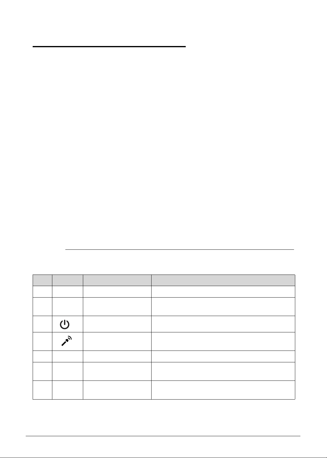
3 Power button Turns the computer on and off.
4 Integrated microphone Internal microphone for sound recording and video
communication.
5 Keyboard For entering data into your computer.
6 Multi-Touch Pad Touch-sensitive pointing device which functions like
a computer mouse.
7 Palmrest Comfortable support area for your hands wh en you
use the computer.
1-8 Hardware Specifications and Configurations
Page 17
Rear View 0
Figure 1-2. Rear View
Table 1-2. Rear View
No. Icon Item Description
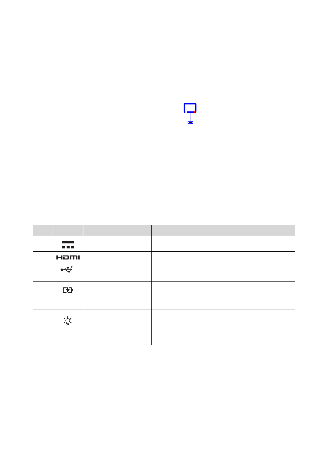
1 DC-in jack Connects to the AC adapter.
2 HDMI port Supports high definition digital video connections.
3 USB 2.0 ports Connects to USB devices (e.g., USB mouse, USB
camera).
4 Battery indicator Indicates the computer’s battery status.
Blue: The computer is in AC mode.
Blinking amber: The battery is charging.
5 Power indicator Indicates the computer’s power status.
Blue: The computer is turned on.
Blinking amber: The computer is in power-saving
mode.
Hardware Specifications and Configurations 1-9
Page 18
Left View 0
Figure 1-3. Left View
Table 1-3. Left View
No. Icon Item Description
1 Headphone/Mic in
combo jack
Connects to combo Headphone/Mic in devices
1-10 Hardware Specifications and Configurations
Page 19
Right View 0
Figure 1-4. Right View
Table 1-4. Right View
No. Icon Item Description
1 2-in-1 card reader Supports MMC, MMCplus, and SD cards.
Note: Only one card can operate at any given
time.
Hardware Specifications and Configurations 1-11
Page 20
Base View 0
Figure 1-5. Base View
Table 1-5. Base View
No. Icon Item Description
1 Battery reset pinhole Insert a paperclip into the hole and press for four
seconds to reset the computer (simulates removing
and reinstalling the battery)
2 Strap Slot For optional strap accessory.
3 Speakers Deliver stereo audio output.
1-12 Hardware Specifications and Configurations
Page 21
Touchpad Basics 0
Figure 1-6. Touchpad
Move finger across the multi-touchpad (1) to move the cursor. Tapping on the
multi-touchpad is the same as clicking the left button of a mouse.
Press the lower left (2) and lower right (3) part of the multi-touchpad to perform
selection and execution functions. These two parts are the equivalent of the left and
right buttons on a mouse.
Table 1-6. Touchpad
Function Touchpad (1) Lower Left (2) Lower Right (3)
Execute Rapidly tap twice. Quickly click twice.
Select Tap once. Click once.
Access context menu Click once.
Hardware Specifications and Configurations 1-13
Page 22
Keyboard 0
The keyboard contains an overlay numeric keys, inverted “T” cursor key, Windows® key,
Application key, function lock keys, and hotkeys controlling various computer features.
Figure 1-7. Keyboard
Lock Keys 0
The keyboard has three lock keys which the user can toggle on and off.
Figure 1-8. Keyboard Lock Keys
Table 1-8. Keyboard Lock Keys
Lock Key Description
Caps Lock When On, all typed alphabetic characters appears in uppercase.
Num Lock
Fn+F11
1-14 Hardware Specifications and Configurations
Off by default. When On, the overlay numeric keys acts as a numeric
keypad. If an external keyboard or keypad is present, the Num Lock will
have the following definitions:
When On, the system boots with external keyboard/keyp ad Num Lock
status On. Internal keyboard overlay numeric keys are disabled.
Page 23
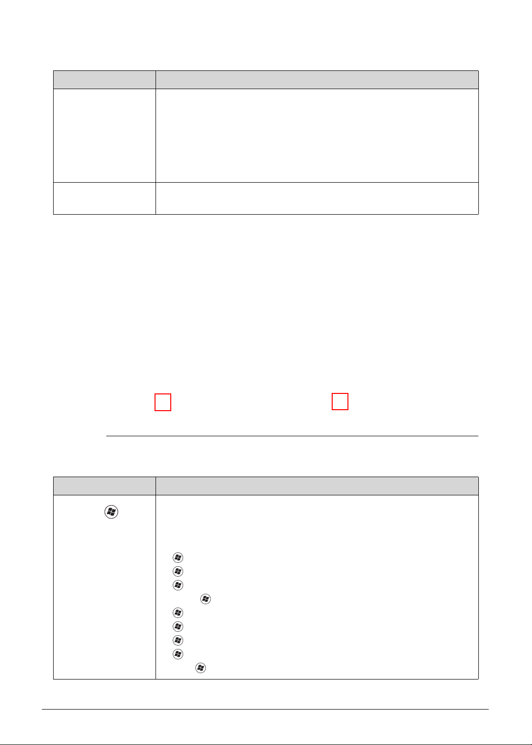
Table 1-8. Keyboard Lock Keys
Lock Key Description
Num Lock
Fn+F11
The key can be turned on/off via the internal keyboard (Fn+F11) or the
external keyboard/keypad. Num Lock affects the external
keyboard/keypad only.
Shift state is NOT required for the cursor movement by the numeric
keys.
The state of the Num Lock is not changed by the attachment/remova l
(hot plug) of the external keyboard/keypad.
Scroll Lock
Fn+F12
When On, the screen moves one line up or down when pressing the up
or down cursor keys. Scroll Lock is not applicable for all applications.
Windows Keys 0
The keyboard has two keys that perform Windows-specific functions.
Figure 1-9. Windows-specific Keys
Table 1-9. Windows-specific Keys
Key Description
Windows
Logo key
Pressed alone, this key has the same effect as clicking on the Windows
Start button; it launches the Start menu. It can also be used with other
keys to provide a variety of functions.
Functions supported by Windows XP, Windows Vista, and Windows 7:
: Open or close the Start menu
+R: Open the Run dialog box
+M: Minimizes all windows
Shift++M: Restore minimized windows to the desktop
+F1: Show the Help window
+ E: Open Windows Explorer
+F: Search for a file or folder
+ D: Display the desktop
Ctrl++F: Search for computers (if you are on a network)
Hardware Specifications and Configurations 1-15
Page 24
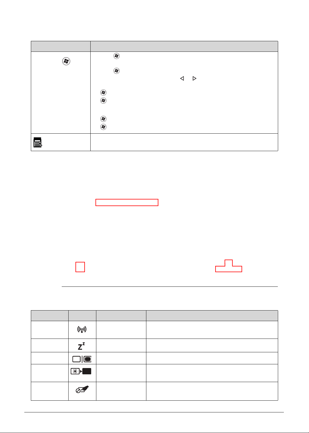
Table 1-9. Windows-specific Keys
Key Description
Windows
Logo key
Ctrl++L: Lock your computer (if you are connected to a netwo r k
domain), or switch users (if you're not connected to a network domain)
Ctrl++Tab: Moves focus from Start menu, to the Quick Launch
toolbar, to the system tray (use or to move focus to items on the
Quick Launch toolbar and the system tray)
+Tab: Cycle through programs on the taskbar
+Break: Display the System Properties dialog box
Functions supported by Windows XP:
+Break: Display the System Properties dialog box
+U: Open the Ease of Access Center window
Application
key
This key has the same effect as clicking the right mouse b utton; it opens
the application's context menu.
Hotkeys 0
The computer uses hotkeys or key combinations to access most computer controls. To
activate hotkeys, press and hold the Fn key before pressing the key in the combination.
Figure 1-10. Hotkeys
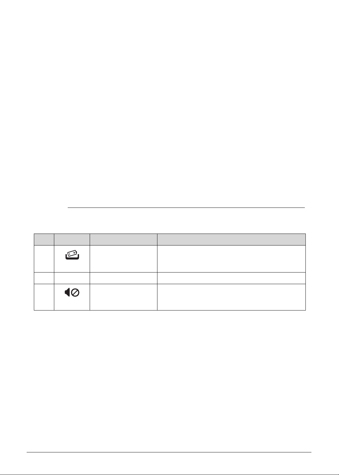
Table 1-10. Hotkeys
Hotkey Icon Function Description
Fn+F3 Communication
device toggle
Toggles the WiFi, 3G and/or Bluetooth functions
On and Off using a pop-up window.
Fn+F4 Sleep Puts the computer in Sleep mode.
Fn+F5 Display off Turns off the LCD back light
Fn+F6 Display toggle Switches the display output between the display
screen, external monitor (if connected) or both.
Fn+F7 Touchpad
Turns the touchpad On or Off.
toggle
1-16 Hardware Specifications and Configurations
Page 25

Table 1-10. Hotkeys
Hotkey Icon Function Description
Fn+F8 Speaker toggle Turns the speakers On or Off.
Fn+ Volume Up Increases the sound volume.
Fn+ Volume Down Decreases the sound volume.
Fn+ Brightness Down Decreases the screen brightness.
Fn+ Brightness Up Increases the screen brightness.
0
Hardware Specifications and Configurations 1-17
Page 26
D2D Recovery 0
2869 2569
60
71
LPC debug port
ENE P2800
ALC271X-VB3
DMIx4
SPI
Flash ROM
8MB
51
HDMI
HDMI
KBC
Thermal
Int.
KB
LPC Bus
Intel CPU
DDRIII 1066/1333 Channel A
4,5,6,7,8,9,10,11,12,13
Left Side:
USB 3.0x 2
CAMERA
49
Mini-Card
802.11a/b/g
LVDS(Single Channel)
Intel
LCD
56
14 USB 2.0/1.1 ports
High Definition Audio
SATA x1
SATA ports (6)
ACPI 1.1
LPC I/F
HDD
Azalia
CODEC
USB2.0 x 3
29
2CH SPEAKER
HP1
Internal Digital MIC
ETHERNET (10/100/1000Mb)
NPCE885P
PCIE ports (8)
NUVOTON
28
Fan
27
49
17,18,19,20,21,22,23,24,25,26
Touch
PAD
FDIx4x2
AZALIA
SMBus
SNB/ IVB
FSB: 1066 MHz
PCH HM77
Cougar Point
RAM x 8
RAM x 8
RAM x 8
RAM x 8
RAM x 8
RAM x 8
RAM x 8
RAM x 8
CardReader
RTS5129
SD/MMC
Card Reader
Board
MINI Board
USB 2.0 x 1
FFC
FPC
FFC
PCI-E x1
USB x1
M-SATA
SATA x1
Charger Circuit
Charger signal
USB3.0 x 2
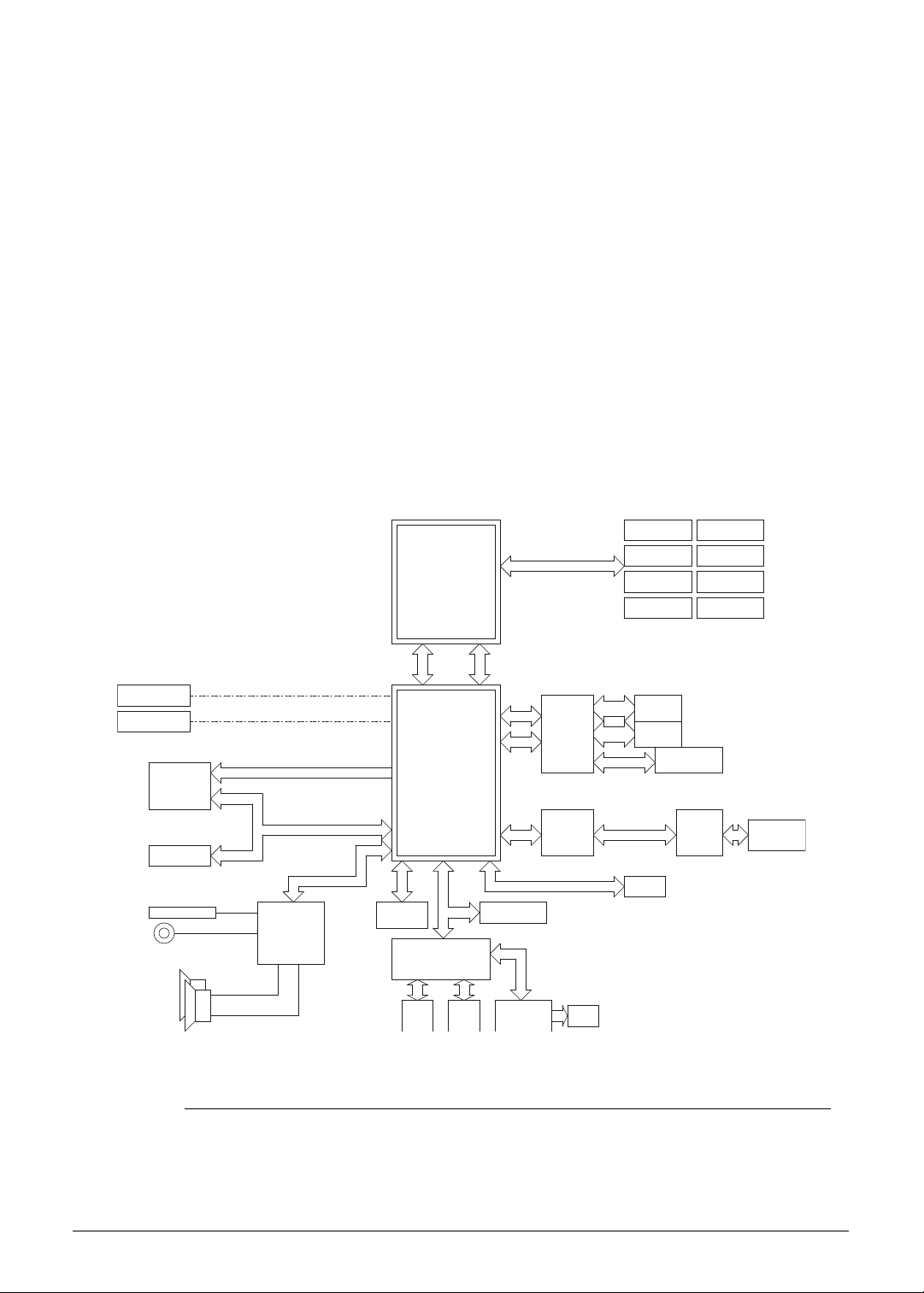
The Acer Disk to Disk (D2D) recovery function allows you to use the recovery partition to
troubleshoot your computer.
1. Restart the computer.
2. During POST, press F1 to access the BIOS Setup screen.
3. Press to select the Main menu.
4. Press to select the D2D Recovery field and make sure it is set to Enabled.
5. Press F10 to save settings and close the BIOS Setup screen.
6. During POST, press Alt+F10 to enter the system recovery partition. This will display the
eRecovery Management window.
7. Follow the onscreen instructions to return your computer to factory condition.
System Block Diagram 0
Figure 1-11. System Block Diagram
1-18 Hardware Specifications and Configurations
Page 27

Specification Tables 0
NOTE:
Computer Specifications
Item Metric Imperial
Dimensions
Width 32.2 cm 12.68 in
Depth 21.85 cm 8.52 in
Height 1.75 cm 0.68 in
Weight (equipped with 3-cell
battery pack)
Input power
Operating voltage 19 V, 65 W
Operating current (max) 3.42 A
Temperature
Operating (not writing to
optical disc)
Operating (writing to optical
disc)
Nonoperating -20 to 60 °C -4 to 140 °F
Relative humidity
Operating 10% to 90%
Nonoperating 5% to 95%
Maximum altitude (unpressurized)
Operating -15 to 3,048 m -50 to 10,000 ft
Nonoperating -15 to 12,192 m -50 to 40,000 ft
1.33 kg with SSD disk drive
1.35 kg with HDD disk drive
0 to 35 °C 32 to 95 °F
5 to 35 °C 41 to 95 °F
2.93 lbs
2.98 lbs
Shock
Operating 125 g, 2 ms, half-sine TBD
Nonoperating 200 g, 2 ms, half-sine TBD
Random vibration
Operating 0.75 g zero-to-peak, 10 to 500 Hz, 0.25 oct/min sweep rate
Non-operating 1.50 g zero-to-peak, 10 to 500 Hz, 0.25 oct/min sweep rate
Applicable product safety standards specify thermal limits for plastic surfaces. The computer
operates well within this range of temperatures.
Hardware Specifications and Configurations 1-19
Page 28
System Board
Item Specification
Core logic
Graphics
USB 2.0
Wireless LAN
Mobile Intel
UMA: Integrated in the Intel
Integrated in the Mobile Intel
Foxconn BCM 43225
Foxconn Atheros HB97
Intel® Centrino® Advanced-N 6205 (Taylor Peak)
®
HM77 (6MB BIOS ROM) Chipset
Audio codec Realtek 271X VB3
Card reader Built-in
Processor
Item Specification
CPU type
Second Generation Intel
Core logic Four execution cores·
L1 cache size: Two 32 KB instruction caches and two 32 KB data
caches
L2 cache size: Two 256 KB
L3 cache size: 3 to 8 MB
®
Core™ Mobile Processor
®
HM65 Express Chipset
®
Core™ Mobile Processor Family
Chipset
Mobile Intel
®
UM67 (4MB SPI) Chipset
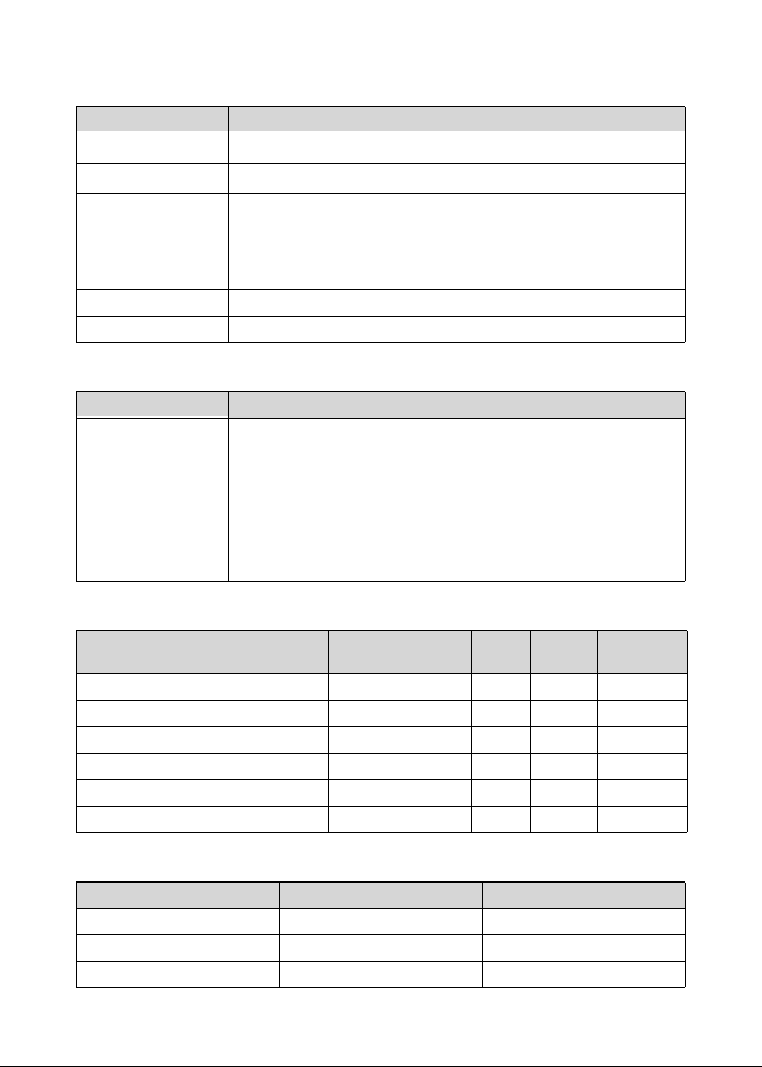
Processor Specifications
Item CPU
Speed
Cores/
Threads
Max T urbo
Freq
Mfg
Tech
L3
Cache
Max
TDP
Core
Voltage
i3-2367M 1.4 GHz 2C/4T 1.4 GHz 32 nm 3 MB 17 W 1.1 V
i3-3217U 1.8 GHz 2C/4T 1.8 GHz 32 nm 3 MB 17 W 1.1 V
i5-2467M 1.6 GHz 2C/4T 2.3 GHz 32 nm 3 MB 17 W 1.1 V
i5-3317U 1.7 GHz 2C/4T 2.3 GHz 32 nm 3 MB 17 W 1.1 V
i7-2637M 1.7 GHz 2C/4T 2.8 GHz 32 nm 4 MB 17 W 1.1 V
i7-3517U 1.9 GHz 2C/4T 2.8 GHz 32 nm 4 MB 17 W 1.1 V
Heat Sink Fan True Value Table
CPU Temperature Fan Speed (RPM) SPL Spec (dBA)
44 2300 25
47 4450 28
52 4850 31
1-20 Hardware Specifications and Configurations
Page 29
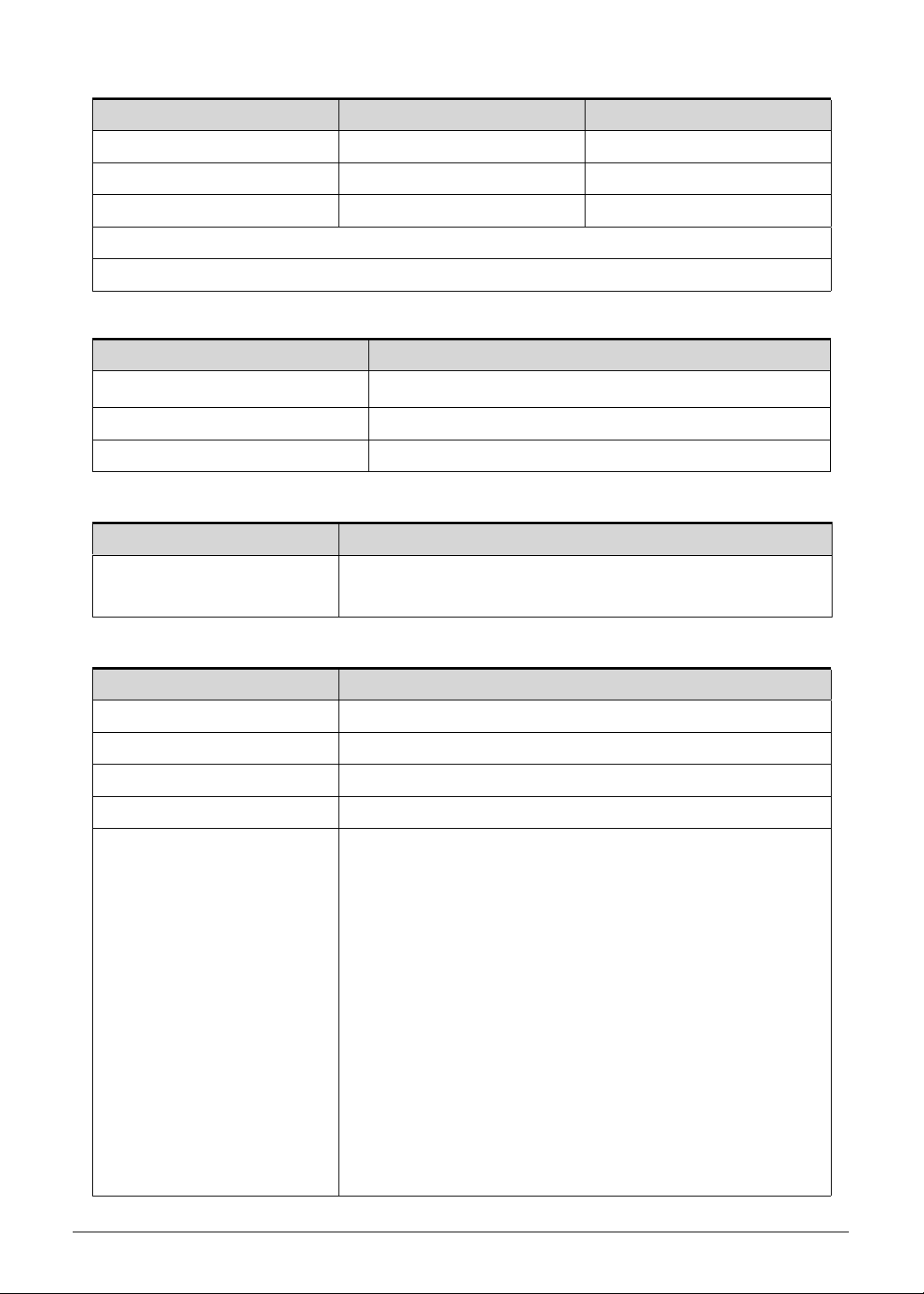
CPU Temperature Fan Speed (RPM) SPL Spec (dBA)
68 5700 34
78 6200 37
85 6500 40
Throttling 50%: On= 85 °C; OFF=84 °C
OS shuts down at 97 °C; Hardware shuts down at 85 °C
System Memory
Item Specification
Memory controller
Integrated in the Intel
Memory size 4 GB onboard
Maximum system memory size 4 GB
Graphics Controller
Item Specification
Chipset
®
Intel
HD Graphics 3000 with 128 MB of dedicated system
memory, supporting Microsoft
System BIOS
Item Specification
BIOS vendor InsydeH2O
BIOS version v1.08
BIOS ROM type Hardware
BIOS ROM size 4 MB
Protocols supported
Legacy BIOS and EFI architectures
ACPI 3.0b compliance
PXE specification v2.1
SMBIOS reference specification v2.5 or later
USB specification revision 1.1, 2.0. and 3.0
ASF specification v2.0 or later
PCI Express base specification revision 2.1
PCI BIOS specification revision 2.1
BIOS Boot specification v1.01
Simple boot flag specification v2.1
System management bus specification v2. 0
AHCI support
Microsoft XP/Vista/Windows 7 logo program
Microsoft SLP 1.0 support
Microsoft OA 2.0 and 2.1 support
®
Core™ Mobile Processor
®
DirectX® 10.1
Hardware Specifications and Configurations 1-21
Page 30
Keyboard
Item Specification
Type Aspire AF1S Flat keyboard
Total number of keys 84 keys
Windows logo key Yes
Internal and external USB
keyboard work simultaneously?
Features
Hard Disk Drive
Item Specification
Vendor and
models
HGST HTS543232A7A384,
Seagate ST320LT020/9YG142-188,
Seagate ST320LT012/9WS14C-188,
Seagate 9YG142-190,
Western Digital WD3200LPVT-22G33T0
Product series
Hitachi Eagle B7/Jaguar B7
Seagate Sapta
Western Digital
Yes
Overlay numeric keys
Inverted “T” cursor keys
Hotkeys for volume and brightness level, media playback,
wireless and sleep functions, and display and touchpad
toggle
Windows and Application keys
Multilanguage support configurable by OEM customer
HGST HTS545050A7E380,
Seagate
ST500LT012/9WS142-188,
Western Digital
WD5000LPVT-22G33T0
Configuration
Interface SATA, Third Generation
Capacity (GB)
320 500
Bytes per sector 512 512
Data heads 3, 2, 2, 2, n/a 4, n/a, 4, n/a
Disks 1, 2/1, 1, 1, n/a 2, n/a, 2, n/a
Performance
Data buffer 8 8
Spindle speed
5400
(RPM)
Media data
875, 875/994, 1175, n/a 875, n/a, n/a, n/a
transfer rate
(Mbits/sec, max)
Interface transfer
300
rate (MB/sec, max)
1-22 Hardware Specifications and Configurations
Page 31

Item Specification
Power
Requirement 5 VDC
Solid State Drive (SSD)
Item Specification
Vendor and
models
A-DATA SSD NAND AS511S7-120GM A-DATA SSD NAND
AS511S7-240GM
Product series A-DATA SSD NAND AS511S7
Configuration
Interface Serial ATA-6Gb/s
Capacity (GB)
120 240
Performance
Max. Read Speed 550MB / s 550MB / s
Max. Read Speed 510MB / s 520MB / s
Power
Requirement 5 VDC
Card Reader
Item Specification
Controller RTS 5209
Cards supported
MultiMediaCard™ (MMC)
MultiMediaCard Plus (MMCplus™)
Secure Digital™ (SD)
Manufacturing technology 65 nm
LCD Panel
Item Specification
Vendor and models B133XTF01.0 LF
Screen size (diagonal) 337.8 mm (13.3 in)
Active area 293.4×165 mm
Display resolution (pixels) HD (1366×768)
Pixel pitch 0.215 mm
Viewing angle (H/V) 90/60
Brightness 200 nit
Contrast ratio 500:1
Hardware Specifications and Configurations 1-23
Page 32

Item Specification
Response time
Typical
Maximum
8ms
16 ms
Typical powe r consumption
3 W
(watt)
Electrical interface 1-channel LVDS
Backlight White LED (WLED)
Weight 310 g
Physical size 306.8 × 189.2 × 3.6 mm
Supported Display Resolutions
Specification UMA
800×600, 60 Hz, 16:9 Yes
1024×768, 60 Hz, 16:9 Yes
1280×600, 60 Hz, 16:9 No
1280×720, 60 Hz, 16:9 Yes
1280×768, 60 Hz, 16:9 Yes
1360×768, 60 Hz, 16:9 Yes
1366×768, 60 Hz, 16:9 Yes
Audio Codec
Item Specification
Controller Conexant CX-20584
Features
98 dB Signal-to-Noise Ratio (A-weighting) for DAC output
90 dB Signal-to-Noise Ratio (A-weighting) for ADC input
Internal Digital Power support: 3.3 V digital core power;
1.5–3.3 V digital IO power for HDA link; 3.0–5.0 V analog
power; 3.0–5.0 V power stage voltage
Acoustic Echo Cancellation (AEC), Noise Suppression (NS),
and Beam Forming (BF) technologies for voice application
48-pin green QFN package
Audio Interface
Item Specification
Controller Conexant CX-20584
Audio onboard Yes
Audio channel Stereo
Resolution 18 bit stereo full duplex
1-24 Hardware Specifications and Configurations
Page 33

Item Specification
Compatibility High Definition Audio Specification
Sampling rate 1 Hz resolution VSR (Variable Sampling Rate)
Internal microphone Yes
Internal speaker/quantity Yes, two speakers
Webcam
Item Specification
Vendor and models
Lite-On HD_S LT_119_SP
Primax PM_S119_SP
Suyin SY_S119_SP
Resolution 1.3 MP HD
Wireless LAN
Item Specification
Module
Broadcom 4313iPA+20702
Foxconn Atheros WB225
Lite-On Atheros WB225
Frequency band 2.4 G Hz
Protocols and data
rates supported
802.11b – 1-11 Mbps
802.11g – 6-54 Mbps
802.11n – 6.5-300 Mbps
Interface PCI Express
Form factor Compact Half-Mini Card
Antennae Yes, two routed in the display assembly
USB Interface
Item Specification
Controller
USB 2.0 – Integrated in the Mobile Intel
®
HM65/HM67/QM67
Express Chipset
Number and location of USB
USB 2.0 – Two (Back)
port
EHCI 2
Output current 1.0A for each connector
HDMI Port
Item Specification
Compliance level HDMI 1.4a
Hardware Specifications and Configurations 1-25
Page 34

Item Specification
Data throughput Up to 16.7 million colors
Number of HDMI port 1
Location Back
System LED Indicators
Item Specification
Power status
Solid blue: The computer is turned on.
Blinking amber: The computer is in power-saving mode.
Indicator off: The computer is turned off.
Battery status AC adapter connected:
Solid blue: The battery charge is at full capacity.
Solid amber: Battery charging.
Blinking amber: Battery is in abnormal stop charge or battery
is in low power state.
AC adapter disconnected:
Blinking amber: Battery charge is in critically low state
Indicator off: Discharging state.
Battery Pack
Item Specification
Vendor and models
Sanyo AP11D Main Common ID:AP11D3F
Sony AP11D Main COMMON ID:AP11D4F
Battery type Lithium-polymer
Pack capacity 3260mAh
Number of battery cell 3
Package configuration 3S2P
AC Adapter
Item Specification
Input rating UMA: 65 W
Input AC current (max) 100-240 V, 1.5 A, 50-60 Hz
Output 19 V, 2-pin
System Power Management
Item Specification
Power management system ACPI 3.0-compliant
1-26 Hardware Specifications and Configurations
Page 35

Item Specification
Power global states G3 Mechanical Off - This off state is entered through a
mechanical means; no electrical current is running through
the circuitry and it can be worked on without damaging the
hardware or endangering service personnel. Except for the
real-time clock, power consumption is zero.
G2/S5 Soft Off - OS initiated shutdown. The computer
consumes a minimal amount of power. No user mode or
system mode code is run. It is not safe to disassemble the
machine in this state.
G1 Sleeping - The computer consumes a small amount of
power, use r mode threads are not being executed, and the
system “appears” to be off. It is not safe to disassemble the
machine in this state
G0 Working - The computer dispatches user mode
(application) threads and they execute. It is not safe to
disassemble the machine in this state.
S4 Non-Volatile Sleep - Also known as hib ernation state. A
special global system state that allows system context to be
saved and restored (relatively slowly) when power is lost to
the mainboard. It is not safe to disassemble the machine in
this state.
Hardware Specifications and Configurations 1-27
Page 36

System DMA Specification
Legacy Mode Power Management
DMA0 Free
DMA1 Free
DMA2 Free
DMA3 Free
DMA4 Direct memory access controller
DMA5 Free
DMA6 Free
DMA7 Free
System Interrupt Specification
Hardware IRQ System Function
IRQ0 System timer
IRQ1 Standard PS/2 keyboard
IRQ2 Not in use
IRQ3 Not in use
IRQ5 Not in use
IRQ6 Not in use
IRQ7 Not in use
IRQ8 System CMOS/real time clock
IRQ9 Not in use
IRQ10 Not in use
IRQ11 Not in use
IRQ12 PS/2 port Touchpad
IRQ13 Numeric data processor
IRQ14 Not in use
IRQ15 Not in use
1-28 Hardware Specifications and Configurations
Page 37

System IO Address Map
I/O address (hex) System Function (shipping configuration)
0000 - 001F Direct Memory Access Controller
0000- 0CF7 PCI bus
0020- 0021 Programmable Interrupt Controller
0024- 0025 Programmable Interrupt Controller
0028- 0029 Programmable Interrupt Controller
002C - 002D Programmable Interrupt Controller
002E - 002F Motherboard resources
0030- 0031 Programmable Interrupt Controller
0034- 0035 Programmable Interrupt Controller
0038- 0039 Programmable Interrupt Controller
003C - 003D Programmable Interrupt Controller
0040 - 0043 System Timer
004E - 004F Motherboard resources
0050- 0053 System Timer
0060- 0060 Standard PS/2 Keyboard
0061- 0061 Motherboard resources
0062- 0062 Microsoft ACPI-Compliant Embedded Controller
0063- 0063 Motherboard resources
0064- 0064 Standard PS/2 Keyboard
0065- 0065 Motherboard resources
0066- 0066 Microsoft ACPI-Compliant Embedded Controller
0067- 0067 Motherboard resources
0068- 006F Motherboard resources
0070- 0070 Motherboard resources
0070- 0077 System CMOS/real time clock
0080- 0080 Motherboard resources
0081- 0091 Direct Memory Access Controller
0092- 0092 Motherboard resources
0093- 009F Direct Memory Access Controller
00A0- 00A1 Programmable Interrupt Controller
00A4- 00A5 Programmable Interrupt Controller
00A8- 00A9 Programmable Interrupt Controller
Hardware Specifications and Configurations 1-29
Page 38

I/O address (hex) System Function (shipping configuration)
00AC - 00AD Programmable Interrupt Controller
00B0- 00B1 Programmable Interrupt Controller
00B2- 00B3 Motherboard resources
00B4- 00B5 Programmable Interrupt Controller
00B8- 00B9 Programmable Interrupt Controller
00BC - 00BD Programmable Interrupt Controller
00C0- 00DF Direct Memory Access Controller
00C0- 00F0 Numeric data processor
03B0- 03BB Intel HD Graphics
03C0- 03DF Intel HD Graphics
0400 - 0453 Motherboard resources
0454 - 0457 Motherboard resources
0458 - 047F Motherboard resources
04D0 - 04D1 Programmable Interrupt Controller
0500 - 057F Motherboard resources
0680 - 069F Motherboard resources
0D00 - FFFF PCI bus
1000 - 100F Motherboard resources
1010 - 1013 Motherboard resources
104E - 104F Motherboard resources
2000 - 203F Intel ® HD Graphics Family
EFA0 - EFBF Intel 7 Series/C216 Series Chipset Family SMBus Controller
2060 - 207F Intel ® 7 Mobile Express Chipset SATA AHCI Controller
2080 - 2087 Intel ® 7 Mobile Express Chipset SATA AHCI Controller
2088 - 208F Intel ® 7 Mobile Express Chipset SATA AHCI Controller
2090 - 2093 Intel ® 7 Mobile Express Chipset SATA AHCI Controller
2094 - 2097 Intel ® 7 Mobile Express Chipset SATA AHCI Controller
FFFF - FFFF Motherboard resources
1-30 Hardware Specifications and Configurations
Page 39

CHAPTER 2
System Utilities
Page 40

BIOS Setup Utility . . . . . . . . . . . . . . . . . . . . . . . . . . . . . . . . . . . . .2-3
Navigating the BIOS Utility . . . . . . . . . . . . . . . . . . . . . . . . . . . .2-3
BIOS Menus . . . . . . . . . . . . . . . . . . . . . . . . . . . . . . . . . . . . . . .2-4
BIOS Flash Utilities. . . . . . . . . . . . . . . . . . . . . . . . . . . . . . . . . . . .2-12
DOS Flash Utility . . . . . . . . . . . . . . . . . . . . . . . . . . . . . . . . . . . .2-13
WinFlash Utility . . . . . . . . . . . . . . . . . . . . . . . . . . . . . . . . . . . . .2-13
Remove HDD/BIOS Password Utilities . . . . . . . . . . . . . . . . . . . .2-14
Removing the HDD Password. . . . . . . . . . . . . . . . . . . . . . . . . .2-14
Removing the BIOS Passwords . . . . . . . . . . . . . . . . . . . . . . . .2-15
Using DMI Tools . . . . . . . . . . . . . . . . . . . . . . . . . . . . . . . . . . . . . .2-16
LAN EEPROM Utility . . . . . . . . . . . . . . . . . . . . . . . . . . . . . . . . .2-16
2-2
Page 41

System Utilities
NOTE:
NOTE:
NOTE:
NOTE:
BIOS Setup Utility 0
This utility is a hardware configuration program built into a computer’s BIOS (Basic
Input/Output System).
The utility is pre-configured and optimized so most users do not need to run it. If configuration
problems occur, the setup utility may need to be run. Refer to Chapter 4, Troubleshooting
when a problem arises.
To enter this utility, during POST (power-on self-test), press
the bottom of screen.
The default setting of the F12 Boot Menu is Disabled. To change the boot device without
entering the BIOS Setup Utility, set the parameter to Enabled. During the next POST, press
F12 to enter the multi-boot menu.
Navigating the BIOS Utility 0
The BIOS Setup Utility has five menu options, namely:
Information
Main
F2 when the prompt appears on
Security
Boot
Exit
Perform the following actions to navigate through the BIOS Setup Utility:
Press to select items in the menu bar.
Press to select an item in the menu screen or in an option box.
Press F5 or F6 to change the parameter value.
Press Esc to exit from the Setup Utility.
Press F9 to load the default settings.
Press F10 to save changes and exit from the Setup Utility.
Parameter values enclosed in square brackets [ ] can be change. Navigation
keys appear on the bottom of the screen. Read the item specific help on the
right area of the screen before making changes to the parameter values.
System information can vary depending on the com p ute r model.
System Utilities 2-3
Page 42

BIOS Menus 0
NOTE:
NOTE:
This section describes the InsydeH2O BIOS Setup Utility menu tabs.
The screenshots used in this chapter are for reference only. Actual values can
vary depending on the computer model.
Information 0
This tab shows a summary of the computer‘s hardware information.
Figure 2-1. Hardware Information
Table 2-1. Hardware Information
Parameter Description
CPU Type Model name and core frequency of the installed processor
CPU Speed Core frequency of the installed processor
HDD Model Name Model name of the installed hard drive
HDD Serial Number Serial number of the installed hard drive
System BIOS Version Current system BIOS version
KBC Version Current keyboard controller version
VGA BIOS Version Current firmware version of the system VGA
Serial Number Serial number of the computer
Asset Tag Number Asset tag number of the computer
2-4 System Utilities
Page 43

Table 2-1. Hardware Information (Continued)
Parameter Description
Product Name Model name of the computer
Manufacturer Name Computer manufacturer
UUID The un ive rsa lly uniqu e iden tifie r tag assign ed to the com p ut er
System Utilities 2-5
Page 44

Main 0
Use this tab to set the system time and date, enable or disable boot options, and enable or
disable the D2D recovery feature.
Figure 2-2. BIOS Main
Table 2-2. BIOS Main
Parameter Description Format/Option
System Time System time expr ess ed in 24-hour format Format: HH:MM:SS
(hour:minute:second)
System Date System date Format MM/DD/YYYY
(month/day/year)
Total Memory Total system memory available –
Video Memory System memory allocated for graphics
processing
Quiet Boot Show the original equipment manufacturer
(OEM) screen during system boot instead of
the typical POST screen
Network Boot Option to boot system from LAN Option: Enabled or
F12 Boot Menu Option to enter the Boot menu during POST Option: Enabled or
D2D Recovery Option to use the D2D Recovery function Option: Enabled or
–
Option: Enabled or
Disabled
Disabled
Disabled
Disabled
SATA Mode Option to set the SATA controller mode Option: AHCI or IDE
2-6 System Utilities
Page 45

Security 0
NOTE:
NOTE:
Use this tab to safeguard and protect the computer from unauthorized use.
Figure 2-3. BIOS Security
Table 2-3. BIOS Security
Parameter Description Option
Supervisor Password Is Supervisor password setting
User Password Is User password setting
HDD Password State Hard drive password setting
Set Supervisor Password Option to set the supervisor password –
Set User Password Option to set a user password –
Set HDD Password Option to set the hard drive p assword –
Password on Boot Option to en ab le password requ ire m en t du rin g
system boot
When prompted to enter the password, three attempts are allowed before
system halts. Resetting the BIOS password may require the user to return the
computer to its dealer.
Clear or Set
Clear or Set
Clear or Set
Enabled or
Disabled
System Utilities 2-7
Page 46

Setting a Password 0
IMPORTANT:
+
NOTE:
NOTE:
Set Supervisor Password
Enter New Password [ ]
Confirm New Password [ ]
Set Supervisor Password
Enter Current Password [ ]
Enter New Password [ ]
Confirm New Password [ ]
Follow the succeeding instructions to set the user or supervisor passwords.
1. Press to highlight a Set _______ Password parameter and press Enter. The Set
_______ Password dialog box appears.
Figure 2-4. Set Supervisor Password
2. Type a new password in the Enter New Password field and press Enter. Passwords
are not case sensitive and the length must not exceed eight alphanumeric characters
(A-Z, a-z, 0-9).
3. Retype the password in the Confirm New Password field and press Enter.
Use care when typing a password. Characters do not appear on the screen.
4. Press Enter.
Users can choose to enable the Password on Boot parameter.
5. Press F10 to save changes and exit from the BIOS Setup Utility.
Removing a Password 0
Perform the following:
1. Press to highlight a Set _______ Password parameter and press Enter. The Set
_______ Password dialog box appears.
Figure 2-5. Set Supervisor Password
2. Type the current password in the Enter Current Password field an d pr es s Enter.
3. Press Enter twice
New Password fields.
4. Press F10 to save changes and exit from the BIOS Setup Utility.
without typing anything in the Enter New Password and Confirm
2-8 System Utilities
Page 47

Changing a Password 0
NOTE:
NOTE:
Set Supervisor Password
Enter Current Password [ ]
Enter New Password [ ]
Confirm New Password [ ]
Setup Notice
Changes have been saved.
[Continue]
1. Press to highlight a Set _______ Password parameter and press Enter. The Set
_______ Password dialog box appears.
Figure 2-6. Set Supervisor Password
2. Type the current password in the Enter Current Password field an d pr es s Enter.
3. Type the new password in the Enter New Password field.
4. Retype the password in the Confirm New Password field.
Figure 2-7. Setup Notice
5. Press Enter. Computer sets Supervisor Password parameter to Set.
Users can choose to enable the Password on Boot parameter.
6. Press F10 to save changes and exit from the BIOS Setup Utility.
System Utilities 2-9
Page 48

Boot 0
Use this tab to set the preferred drive sequence in wh ich the Setup Utili ty attempts to boot the
operating system. By default, the computer searches for boot devices in the following order:
1. Hard disk drive
2. External USB bootable device
3. Network boot
4. External USB hard drive
5. External USB optical drive
Press to select a device and press F5 or F6 to move it up or down the list.
Figure 2-8. BIOS Boot
2-10 System Utilities
Page 49

Exit 0
Use the Exit tab to save or discard changes and close the BIOS Setup Utility.
Figure 2-9. BIOS Exit
Table 2-4. Exit Parameters
Parameter Description
Exit Saving Changes Close the BIOS Setup Utility and save the setup changes.
Exit Discarding Changes Close the BIOS Setup Utility without saving the setup changes.
Load Setup Default Load the default values for all setup items.
Discard Changes Load the previous values for all setup items.
Save Changes Save the setup changes.
System Utilities 2-11
Page 50

BIOS Flash Utilities 0
NOTE:
NOTE:
NOTE:
NOTE:
NOTE:
NOTE:
NOTE:
NOTE:
BIOS Flash memory updates are required for the following conditions:
New versions of system programs
New features or options
Restore a BIOS when it becomes corrupted.
Use the Flash utility to update the system BIOS Flash ROM.
If a Crisis Recovery Disc is not available, create one before Flash utility is used.
Do not install memory related drivers (XMS, EMS, DPMI) when Flash is used.
Use AC adaptor power supply when running Flash utility. If battery pack does
not contain power to finish loading BIOS Flash, do not boot system.
Perform the following to run Flash.
1. Rename the BIOS file as “XXXXXXX.FD”.
2. Copy the “XXXXXXX.FD” file to a bootable USB device containing the Crisis Recovery
disk files.
3. T urn off the computer.
4. Insert the USB device containing the renam ed BIOS file and the Crisis Recovery disk files
to any USB port.
5. Press and hold the Fn + Esc keys (this is the BIOS recovery hotkey), then press the
power button.
6. Release the Fn + Esc keys after POST.
Flash utility has auto execution function.
2-12 System Utilities
Page 51

DOS Flash Utility 0
Perform the following to use the DOS Flash Utility:
1. Press F2 during boot to enter Setup Menu.
2. Select Boot Menu to modify boot priority order.
Example: If using USB HDD to Update BIOS, move USB HDD to position 1.
Figure 2-10. BIOS Boot
3. Insert the USB HDD and reboot computer.
4. Execute <BIOS.BAT> to update BIOS.
WinFlash Utility 0
Perform the following to use the WinFlash Utility:
1. Double click the WinFlash executable file.
2. Click OK to begin the update.
System Utilities 2-13
Page 52

Remove HDD/BIOS Password Utilities 0
NOTE:
NOTE:
NOTE:
NOTE:
Password Error Status
HDD password error code
This section explains how to remove the HDD and BIOS passwords.
Removing the HDD Password 0
If the incorrect HDD password is entered three times in succession, an error is
generated. (Figure 2-11)
Figure 2-11. Password Error Status
To reset the HDD password:
1. Open the computer in a DOS environment.
2. Type the following command:
A\> unlockhd XXXXXXXX
Figure 2-12. Unlock Key Code
XXXXXXXX = HDD Password Error Code
3. Press Enter to generate a new password.
Figure 2-13. Password Encoding
4. Write down the generated master password.
5. Reboot the computer.
6. In the HDD password prompt, type the master password generated in step 3, then press
Enter.
2-14 System Utilities
Page 53

Removing the BIOS Passwords 0
To clear a lost BIOS password (user or supervisor password), you need to short the clear
password hardware gap (G2201) located on the mainboard. Refer to the “Clearing the BIOS
Passwords” on page 5-5 section for detailed instructions.
Figure 2-14. G2201 Hardware Gap
System Utilities 2-15
Page 54

Using DMI Tools 0
The DMI (Desktop Management Interface) Tool copies BIOS information to EEPROM
(Electrically Erasable Programmable Read-Only Memory). Used in the DMI pool for h ardware
management.
LAN EEPROM Utility 0
LAN EEPROM Utility enables to change the MAC address.
Perform the following steps to use the LAN EEPROM Utility:
1. Create a DOS bootable USB HDD.
2. Copy the contents of the MAC folder to the HDD and remove the HDD form the computer.
3. Reboot the computer and press F2 during the boot sequence to enter the setup menu.
4. Select the Boot menu item and move the entry “USB HDD” to the first position.
Figure 2-15. BIOS Boot
5. Connect the USB HDD and reboot the computer.
6. At the command prompt, navigate to the MAC folder.
7. Execute the < MAC.BAT> file.
8. At prompt type in MAC address.
9. Press Enter.
10. Reboot when the process has completed.
2-16 System Utilities
Page 55

CHAPTER 3
Machine Maintenance
Page 56

Machine Disassembly and Replacement . . . . . . . . . . . . . . . . . .3-3
Recommended Equipment . . . . . . . . . . . . . . . . . . . . . . . . . . . .3-3
Replacement Requirements . . . . . . . . . . . . . . . . . . . . . . . . . . .3-3
Pre-disassembly Instructions. . . . . . . . . . . . . . . . . . . . . . . . . . .3-4
Disassembly Process. . . . . . . . . . . . . . . . . . . . . . . . . . . . . . . . . .3-5
Removing the Lower Case . . . . . . . . . . . . . . . . . . . . . . . . . . . .3-7
Removing the Battery Pack. . . . . . . . . . . . . . . . . . . . . . . . . . . .3-8
Removing the Left and Right Speakers. . . . . . . . . . . . . . . . . . .3-11
Removing the WLAN Module . . . . . . . . . . . . . . . . . . . . . . . . . .3-13
Removing the DC-In Module (WLAN Board). . . . . . . . . . . . . . .3-15
Removing the DC-In Module (M-SATA Board) . . . . . . . . . . . . .3-16
Removing the HDD Module. . . . . . . . . . . . . . . . . . . . . . . . . . . .3-17
Removing the SSD Module . . . . . . . . . . . . . . . . . . . . . . . . . . . .3-20
Removing the Card Reader Board . . . . . . . . . . . . . . . . . . . . . .3-23
Removing the Mainboard. . . . . . . . . . . . . . . . . . . . . . . . . . . . . .3-25
Removing the Thermal Module . . . . . . . . . . . . . . . . . . . . . . . . .3-29
Removing the RTC Battery . . . . . . . . . . . . . . . . . . . . . . . . . . . .3-31
Removing the WLAN Board. . . . . . . . . . . . . . . . . . . . . . . . . . . .3-32
Removing the M-SATA Board . . . . . . . . . . . . . . . . . . . . . . . . . .3-33
Removing the Keyboard . . . . . . . . . . . . . . . . . . . . . . . . . . . . . .3-34
Removing the Power Button Board . . . . . . . . . . . . . . . . . . . . . .3-36
Removing the Middle Cover Assembly . . . . . . . . . . . . . . . . . . .3-37
Removing the LCD Module . . . . . . . . . . . . . . . . . . . . . . . . . . . .3-39
3-2
Reassembly Process . . . . . . . . . . . . . . . . . . . . . . . . . . . . . . . . . .3-41
Replacing the LCD Module . . . . . . . . . . . . . . . . . . . . . . . . . . . .3-41
Replacing the Middle Cover Assembly . . . . . . . . . . . . . . . . . . .3-43
Replacing the Power Button Board . . . . . . . . . . . . . . . . . . . . . .3-45
Replacing the Keyboard . . . . . . . . . . . . . . . . . . . . . . . . . . . . . .3-46
Replacing the WLAN Board. . . . . . . . . . . . . . . . . . . . . . . . . . . .3-48
Replacing the M-SATA Board.. . . . . . . . . . . . . . . . . . . . . . . . . .3-49
Replacing the RTC Battery . . . . . . . . . . . . . . . . . . . . . . . . . . . .3-50
Replacing the Thermal Module . . . . . . . . . . . . . . . . . . . . . . . . .3-51
Replacing the Mainboard. . . . . . . . . . . . . . . . . . . . . . . . . . . . . .3-53
Replacing the Card Reader Board. . . . . . . . . . . . . . . . . . . . . . .3-57
Replacing the HDD Module. . . . . . . . . . . . . . . . . . . . . . . . . . . .
3-59
Replacing the SSD Module . . . . . . . . . . . . . . . . . . . . . . . . . . . .3-62
Replacing the DC-In Module (WLAN Board). . . . . . . . . . . . . . .3-65
Replacing the DC-In Module (M-SATA Board) . . . . . . . . . . . . .3-66
Replacing the WLAN Module. . . . . . . . . . . . . . . . . . . . . . . . . . .3-67
Replacing the Right Speakers. . . . . . . . . . . . . . . . . . . . . . . . . .3-69
Page 57

Replacing the Battery Pack . . . . . . . . . . . . . . . . . . . . . . . . . . . .3-71
Replacing the Lower Case. . . . . . . . . . . . . . . . . . . . . . . . . . . . .3-74
3-3
Page 58

3-4
Page 59

Machine Maintenance
NOTE:
NOTE:
Machine Disassembly and Replacement 0
This chapter contains step-by-step procedures on how to disassemble the notebook
computer for maintenance and troubleshooting.
Cable paths and positioning may not represent the actual model. Dur ing the removal and
installation of the components, ensure all available cable channels and clips are used and
that the cables are replaced in the same position.
The screws for the different components vary in size. During the disassembly process, group
the screws with the corresponding components to avoid mismatch when putting ba ck the
components.
The product previews seen in the disassembly procedures may not represent the final
product color or configuration.
Recommended Equipment 0
To disassemble the computer, the following tools are suggested:
Wrist grounding strap and conductive mat for preventing electrostatic discharge
Non-marring scribe
Phillips screwdriver
Flat-blade screwdriver
Plastic flat screwdriver
Plastic tweezers
Cyanoacrylate glue
Replacement Requirements 0
Cabling and components require adhesive to be applied during the replacement and
reassembly process.
Machine Maintenance 3-5
Page 60

Pre-disassembly Instructions 0
Before proceeding with the disassembly procedure, make sure that you do the following:
1. T urn off the power to the system and all peripherals.
2. Unplug the AC adapter and all power and signal cables from the system .
Figure 3-1. AC Adapter
3. Remove any dummy cards that are present.
4. Place the system on a flat, stable surface.
3-6 Machine Maintenance
Page 61

Disassembly Process 0
LOWER
CASE
BATTERY
PACK
HDD / SSD
MODULE
SPEAKER
MODULE
DC-IN
MODULE
MAIN
BOARD
LCD
MODULE
RTC
BATTERY
POWER
BUTTON
BOARD
CARD
READER
BOARD
THERMAL
MODULE
WLAN /
M-SATA
BOARD
WLAN
MODULE
MIDDLE
COVER
KEYBOARD
The flowchart provided in this disassembly section illustrate the entire disassembly sequence.
Observe the order of the sequence to avoid damag e to any of the h ardware com ponents. For
example, if you want to remove the WLAN/M-SATA board, you must first remove the battery
pack, then the WLAN module, in that order.
Figure 3-2. Disassembly Flowchart
Table 3-2. Screw List
Step Screw Quantity Acer Part Number
Lower Case Disassembly M2 x L4.5 12 86.EA552.4R5
Battery Pack Disassembly M2 x L4.5 2 86.EA552.4R5
Speaker Module Disassembly M1.4 x L3 4 86.EA36N.3R0
WLAN Module Disassembly M2 x L3 1 86.00E14.523
DC-In Module Disassembly - - HDD/SSD Module Disassembly M2 x L3 1 86.00E14.523
M3 x L4 4 86.9A524.4R0
Card Reader Board Disassembly M2 x L3 2 86.00E14.523
Thermal Module Disassembly Thermal Screw 3 N/A
Power Button Board Disassembly - - -
Machine Maintenance 3-7
Page 62

Table 3-2. Screw List
Step Screw Quantity Acer Part Number
Mainboard Disassembly M2 x L3 1 86.00E14.523
RTC Battery Disassembly - - WLAN Board Disassembly - - Keyboard Disassembly M1.4 x L1.2 29 86.EA322.2R0
Middle Cover Disassembly M2 x L3 4 86.00E14.523
LCD Module Disassembly M2 x L4.5 4 86.EA552.4R5
3-8 Machine Maintenance
Page 63

Removing the Lower Case 0
1. Remove the twelve screws securing the lower case.
Figure 3-3. Lower Case Screws
Table 3-3. Screws
Step Screw Quantity Screw Type
Lower Case Disassembly M2 x L4.5 12
2. Gently lift the lower case and lay it down beside the main unit.
Figure 3-4. Lower Case
Machine Maintenance 3-9
Page 64

Removing the Battery Pack 0
1. Perform the “Removing the Lower Case” procedure described on page 3-9.
2. Remove the two screws securing the left speaker to the upper case.
Figure 3-5. Left Speaker Screws
Table 3-5. Screws
Step Screw Quantity Screw Type
Left Speaker Module Disassembly M1.4 x L3 2
3. Lift the left speaker off the upper case and temporarily place it at the side of the right
speaker.
Figure 3-6. Left Speaker
3-10 Machine Maintenance
Page 65

4. Lift the DC-In & Power cable off the battery pack.
Figure 3-7. DC-In & Power Cable
5. Remove the two screws securing the battery p ack to the upper case.
Figure 3-8. Battery Pack Screws
Table 3-8. Screws
Step Screw Quantity Screw Type
Battery Pack Disassembly M2 x L4.5 2
Machine Maintenance 3-11
Page 66

6. Lift the battery pack off its socket in the upper case then slide it a few millimeters away
NOTE:
NOTE:
from the mainboard (1). Disconnect the battery cable from the WLAN board (2).
Figure 3-9. Battery Cable
7. Detach the battery pack from the upper case.
Figure 3-10. Battery Pack
The battery has been highlighted with the yellow bord e r in Figure 3-10. Remove the
battery and follow local regulations for disposal.
3-12 Machine Maintenance
Page 67

Removing the Left and Right Speakers 0
1. Perform the “Removing the Lower Case” procedure described on page 3-9.
2. Perform the “Removing the Battery Pack” procedure described on page 3-10.
3. Remove the two screws securing the right speakers to the upper case (1).
Figure 3-11. Right Speaker Screws and Adhesive Tape
Table 3-11. Screws
Step Screw Quantity Screw Type
Right Speaker Module Disassembly M1.4 x L3 2
4. Release the speaker cable from the adhesive tape securing it (2).
5. Detach the right speaker from the upper case.
Figure 3-12. Right Speaker
Machine Maintenance 3-13
Page 68

6. Disconnect the speaker’s cable from the mainboard.
Figure 3-13. Speaker Cable
3-14 Machine Maintenance
Page 69

Removing the WLAN Module 0
IMPORTANT:
+
1. Perform the “Removing the Lower Case” procedure described on page 3-9.
2. Perform the “Removing the Battery Pack” procedure described on page 3-10.
3. Unplug the two antenna cables from the WLAN module.
Figure 3-14. WLAN Module Antennas
For reference during machine reassembly, note which cable color
corresponds to the main (black) and auxiliary (white) connectors.
4. Release the antenna cables from the adhesive tapes securing it.
Figure 3-15. Antenna Cables Adhesive Tapes
Machine Maintenance 3-15
Page 70

5. Remove the screw securing the WLAN module to the WLAN/M-SATA board.
NOTE:
NOTE:
Figure 3-16. WLAN Module Screw
Table 3-16. Screw
Step Screw Quantity Screw Type
WLAN Module Disassembly M2 × L3 1
6. Detach the WLAN module from the slot.
Figure 3-17. WLAN Module
A circuit board that is > 10cm2 has been highlighted with a yellow rectangle in
Figure 3-17. Follow the local regulations for disposing this type of circuit board.
3-16 Machine Maintenance
Page 71

Removing the DC-In Module (WLAN Board) 0
NOTE:
NOTE:
For models that have M-SA TA board installed, please proceed to page 3-18, “Removing
the DC-In Module (M-SATA Board)”
1. Perform the “Removing the Lower Case” procedure described on page 3-9.
2. Perform the “Removing the Battery Pack” procedure described on page 3-10.
3. Disconnect the DC-In cable from the WLAN board (1) then release the DC-In cable from
the self adhesive tape securing it (2).
Figure 3-18. DC-In Cable (WLAN Board)
4. Detach the DC-In socket from the upper case.
Figure 3-19. DC-In
Machine Maintenance 3-17
Page 72

Removing the DC-In Module (M-SATA Board) 0
1. Perform the “Removing the Lower Case” procedure described on page 3-9.
2. Perform the “Removing the Battery Pack” procedure described on page 3-10.
3. Disconnect the DC-In ca ble from the M-SATA board & the mainboard (1) then rele ase the
DC-In cable from the self adhesive tape securing it (2).
Figure 3-20. DC-In Cable (M-SATA Board)
4. Detach the DC-In socket from the upper case.
Figure 3-21. DC-In
3-18 Machine Maintenance
Page 73

Removing the HDD Module 0
NOTE:
NOTE:
For models that have SSD disk drive installed, please proceed to page 3-22, “R emoving
the SSD Module”.
1. Perform the “Removing the Lower Case” procedure described on page 3-9.
2. Perform the “Removing the Battery Pack” procedure described on page 3-10.
3. Release the HDD cable from the adhesive tape securing it.
Figure 3-22. HDD Cable Adhesive Tape
4. Grasp the plastic tab and use it to disengage the HDD cable from its connector.
Figure 3-23. HDD Cable
Machine Maintenance 3-19
Page 74

5. Remove the screw securing the HDD module to the upper case.
Figure 3-24. HDD Module Screw
Table 3-24. Screw
Step Screw Quantity Screw Type
HDD Module Disassembly M2 x L3 1
6. Detach the HDD module from the upper case.
Figure 3-25. HDD Module
3-20 Machine Maintenance
Page 75

7. Detach the cable from the HDD module.
Figure 3-26. HDD Cable
8. Remove the four screws securing the HDD module to the bracket (1) then detach the HDD
module from the bracket (2).
Figure 3-27. HDD Bracket Screws
Table 3-27. Screws
Step Screw Quantity Screw Type
HDD Bracket Disassembly M3 x L4 4
Machine Maintenance 3-21
Page 76

Removing the SSD Module 0
1. Perform the “Removing the Lower Case” procedure described on page 3-9.
2. Perform the “Removing the Battery Pack” procedure described on page 3-10.
3. Release the SSD cable from the adhesive tape securing it.
Figure 3-28. SSD Cable Adhesive Tape
4. Grasp the plastic tab and use it to disengage the SSD cable from its connector.
Figure 3-29. SSD Cable
3-22 Machine Maintenance
Page 77

5. Remove the screw securing the SSD module to the upper case.
Figure 3-30. SSD Module Screw
Table 3-30. Screw
Step Screw Quantity Screw Type
SSD Module Disassembly M2 x L3 1
6. Detach the SSD module from the upper case.
Figure 3-31. SSD Module
Machine Maintenance 3-23
Page 78

7. Detach the cable from the SSD module.
Figure 3-32. SSD Cable
8. Remove the four screws securing the SSD module to the bracket ( 1) then det ach the SSD
module from the bracket (2).
Figure 3-33. SSD Bracket Screws
Table 3-33. Screws
Step Screw Quantity Screw Type
SSD Bracket Disassembly M3 x L4 4
3-24 Machine Maintenance
Page 79

Removing the Card Reader Board 0
1. Perform the “Removing the Lower Case” procedure described on page 3-9.
2. Perform the “Removing the Battery Pack” procedure described on page 3-10.
3. Disconnect the card reader cable from the mainboard and the card reader board.
Figure 3-34. Card Reader Cable
4. Remove the two screws securing the card reader board to the upper case.
Figure 3-35. Card Reader Board Screws
Table 3-35. Screws
Step Screw Quantity Screw Type
Card Reader Board Disassembly M2 x L3 2
Machine Maintenance 3-25
Page 80

5. Detach the card reader board from the upper case.
NOTE:
NOTE:
Figure 3-36. Card Reader Board
A circuit board that is > 10cm2 has been highlighted with a yellow rectangle in
Figure 3-36. Follow the local regulations for disposing this type of circuit board.
3-26 Machine Maintenance
Page 81

Removing the Mainboard 0
1. Perform the “Removing the Lower Case” procedure described on page 3-9.
2. Perform the “Removing the Battery Pack” procedure described on page 3-10.
3. Release the connector latch (1) from the mainboard, then disconnect the touchpad cable (2).
Figure 3-37. Touchpad Cable
4. Release the connector latches (1) from the mainboard, then disconnect the WLAN & mini
1 cables (2). Disconnect the power cable from the mainboard (3).
Figure 3-38. WLAN, Mini 1 & Power Cables
Machine Maintenance 3-27
Page 82

5. Release the connector latch (1) from the mainboard, then disconnect the power button
cable (2).
Figure 3-39. Power Button Cable
6. Release the latch (1) from the mainboard then disconnect the keyb oard cable (2).
Figure 3-40. Keyboard Cable
3-28 Machine Maintenance
Page 83

7. Release the LCD cable from the adhesive tape securing it.
Figure 3-41. LCD Cable Adhesive Tape
8. Disconnect the LCD cable from the mainboard.
Figure 3-42. LCD Cable
Machine Maintenance 3-29
Page 84

9. Remove the screw securing the mainbo ard to the upper case.
NOTE:
NOTE:
Figure 3-43. Mainboard Screw
Table 3-43. Screw
Step Screw Quantity Screw Type
Mainboard Disassembly M2 × L3 1
10. Detach the mainboard from the upper case.
Figure 3-44. Mainboard
A circuit board that is > 10cm2 has been highlighted with a yellow rectangle in
Figure 3-44. Follow the local regulations for disposing this type of circuit board.
3-30 Machine Maintenance
Page 85

Removing the Thermal Module 0
1. Perform the “Removing the Lower Case” procedure described on page 3-9.
2. Perform the “Removing the Battery Pack” procedure described on page 3-10.
3. Disconnect the thermal module fan cable from the mainboard.
Figure 3-45. Fan Cable
4. Loosen the spring-loaded captive screws securing the thermal module. Follow the screw
sequence indicated on Figure 3-46.
Figure 3-46. Thermal Module Screws
Table 3-46. Screws
Step Screw Quantity Screw Type
Thermal Module Disassembly – 3 –
Machine Maintenance 3-31
Page 86

5. Detach the thermal module from the mainboard.
Figure 3-47. Thermal Module
3-32 Machine Maintenance
Page 87

Removing the RTC Battery 0
NOTE:
NOTE:
1. Perform the “Removing the Lower Case” procedure described on page 3-9.
2. Perform the “Removing the Battery Pack” procedure described on page 3-10.
3. Perform the “Removing the Mainboard” procedure described on page3-27.
4. Disconnect the RTC battery cable from the mainboard.
Figure 3-48. RTC Battery Cable
5. Detach the RTC battery from the mainboard.
Figure 3-49. RTC Battery
The battery has been highlighted with the yellow circle in Figure 3-49. Remove the
battery and follow local regulations for disposal.
Machine Maintenance 3-33
Page 88

Removing the WLAN Board 0
NOTE:
NOTE:
NOTE:
NOTE:
For models that have M-SA TA board installed, please proceed to page 3-35, “Removing
the M-SATA Board”.
1. Perform the “Removing the Lower Case” procedure described on page 3-9.
2. Perform the “Removing the Battery Pack” procedure described on page 3-10.
3. Perform the “Removing the WLAN Module” procedure described on page 3-15.
4. Release the connector latches (1) from the WLAN board, then disconnect the WLAN &
mini 1 cables (2). Disconnect the power cable from the WLAN board (3).
Figure 3-50. WLAN, Mini 1 & Power Cables
5. Detach the WLAN board from the upper case.
Figure 3-51. WLAN Board
A circuit board that is > 10cm2 has been highlighted with a yellow rectangle in
Figure 3-51. Follow the local regulations for disposing this type of circuit board.
3-34 Machine Maintenance
Page 89

Removing the M-SATA Board 0
NOTE:
NOTE:
1. Perform the “Removing the Lower Case” procedure described on page 3-9.
2. Perform the “Removing the Battery Pack” procedure described on page 3-10.
3. Perform the “Removing the WLAN Module” procedure described on page 3-15.
4. Release the connector latches (1) from the M-SATA board, then disconnect the WLAN &
mini 1 cables (2).
Figure 3-52. WLAN & Mini 1 Cables
5. Detach the M-SATA board from the upper case.
Figure 3-53. M-SATA Board
A circuit board that is > 10cm2 has been highlighted with a yellow rectangle in
Figure 3-53. Follow the local regulations for disposing this type of circuit board.
Machine Maintenance 3-35
Page 90

Removing the Keyboard 0
NOTE:
NOTE:
The keyboard is easily warped or damaged during the removal proce ss. Take care not
to use excessive force when removing.
1. Perform the “Removing the Lower Case” procedure described on page 3-9.
2. Perform the “Removing the Battery Pack” procedure described on page 3-10.
3. Perform the “Removing the Left and Right Speakers” procedure described on page 3-13.
4. Perform the “Removing the WLAN Module” procedure described on page 3-15.
5. Perform the “Removing the DC-In Module (WLAN Board)” procedure described on
page 3-17.
6. Perform the “Removing the HDD Module” procedure described on page 3-19.
7. Perform the “Removing the Card Reader Board” procedure described on page 3-25.
8. Perform the “Removing the Mainboard” procedure described on page3-27.
9. Perform the “Removing the WLAN Board” procedure described on page 3-34.
10. Gently lift the LCD cable off the upper case.
Figure 3-54. LCD Cable
11. Release the keyboard from the adhesive tape securing it.
Figure 3-55. Keyboard Adhesive Tape
3-36 Machine Maintenance
Page 91

12. Remove the twenty nine screws securing the keyboard to the upper case.
Figure 3-56. Keyboard Screws
Table 3-56. Screws
Step Screw Quantity Screw Type
Keyboard Disassembly M1.4 × L1.2 29
13. Detach the keyboard from the upper case.
Figure 3-57. Keyboard
Machine Maintenance 3-37
Page 92

Removing the Power Button Board 0
NOTE:
NOTE:
1. Perform the “Removing the Lower Case” procedure described on page 3-9.
2. Perform the “Removing the Battery Pack” procedure described on page 3-10.
3. Release the latch (1) from the mainboard then disconnect the power button cable (2).
Figure 3-58. Power Button Cable
4. Release the power button board from the adhesive tape securing it (1) then tilt the power
button board (2) and detach it from the upper ca se .
Figure 3-59. Power Button Board Adhesive Tape
A circuit board that is > 10cm2 has been highlighted with a yellow rectangle in
Figure 3-59. Follow the local regulations for disposing this type of circuit board.
3-38 Machine Maintenance
Page 93

Removing the Middle Cover Assembly 0
1. Perform the “Removing the Lower Case” procedure described on page 3-9.
2. Perform the “Removing the Battery Pack” procedure described on page 3-10.
3. Perform the “Removing the Left and Right Speakers” procedure described on page 3-13.
4. Perform the “Removing the WLAN Module” procedure described on page 3-15.
5. Perform the “Removing the DC-In Module (WLAN Board)” procedure described on
page 3-17.
6. Perform the “Removing the HDD Module” procedure described on page 3-19.
7. Perform the “Removing the Card Reader Board” procedure described on page 3-25.
8. Perform the “Removing the Mainboard” procedure described on page3-27.
9. Perform the “Removing the Keyboard” procedure described on page 3-36.
10. Perform the “Removing the Power Button Board” procedure described on page 3-38.
11. Remove the four screws securing the middle cover assembly to the upper case.
Figure 3-60. Middle Cover Assembly Screws
Table 3-60. Screws
Step Screw Quantity Screw Type
Middle Cover Disassembly M2 x L3 4
Machine Maintenance 3-39
Page 94

12. Tilt the upper case until it is approximately at a 100° angle with the LCD assembly.
Figure 3-61. Upper Case Assembly
13. Detach the middle cover assembly from the upper case.
Figure 3-62. Middle Cover Assembly
3-40 Machine Maintenance
Page 95

Removing the LCD Module 0
1. Perform the “Removing the Lower Case” procedure described on page 3-9.
2. Perform the “Removing the Battery Pack” procedure described on page 3-10.
3. Perform the “Removing the Left and Right Speakers” procedure described on page 3-13.
4. Perform the “Removing the WLAN Module” procedure described on page 3-15.
5. Perform the “Removing the DC-In Module (WLAN Board)” procedure described on
page 3-17.
6. Perform the “Removing the HDD Module” procedure described on page 3-19.
7. Perform the “Removing the Card Reader Board” procedure described on page 3-25.
8. Perform the “Removing the Mainboard” procedure described on page3-27.
9. Perform the “Removing the Keyboard” procedure described on page 3-36.
10. Perform the “Removing the Power Button Board” procedure described on page 3-38.
11. Perform the “Removing the Middle Cover Assembly” procedure described on page 3-39.
12. Tilt the upper case until it is approximately at a 45° angle with the LCD assembly.
Figure 3-63. Upper Case Assembly
Machine Maintenance 3-41
Page 96

13. Remove the four screws securing the upper case to the LCD hinges.
IMPORTANT:
+
Figure 3-64. Upper Case Screws – LCD Hinges
Table 3-64. Screws
Step Screw Quantity Screw Type
LCD Module Disassembly M2 x L4.5 4
14. Gently detach the LCD cable from the upper case (1) and lift the upper case away from
the LCD module (2).
Figure 3-65. LCD Module
Make sure that the LCD cable is not entangled with the upper ca se and take
extra care not to scratch the LCD cable.
3-42 Machine Maintenance
Page 97

Reassembly Process 0
IMPORTANT:
+
Replacing the LCD Module 0
1. Tilt the LCD hinge approximately at a 45° angle then insert the upper case and align the
screw posts of the upper case with the screw holes in the LCD hinges.
Figure 3-66. Upper Case
2. Verify that the LCD cable is looped properly in the LCD hing e as show n.
Figure 3-67. Upper Case
Make sure that the LCD cable is not entangled with the upper ca se and take
extra care not to scratch the LCD cable.
Machine Maintenance 3-43
Page 98

3. Secure the upper case to the LCD hinges using four screws.
Figure 3-68. Upper Case - LCD Hinge Screws
Table 3-68. Screws
Step Screw Quantity Screw Type
Upper Case Reassembly M2 x L4.5 4
3-44 Machine Maintenance
Page 99

Replacing the Middle Cover Assembly 0
1. Tilt the upper case until it is approximately at a 100° angle with the LCD assembly
Figure 3-69. Upper Case Assembly
2. Insert the middle cover assembly in its slot.
Figure 3-70. Middle Cover Assembly
Machine Maintenance 3-45
Page 100

3. Pull the upper case downward until it sits parallel with the LCD assembly.
Figure 3-71. Upper Case Assembly
4. Secure the middle cover assembly to the upper case using four screws.
Figure 3-72. Middle Cover Assembly Screws
Table 3-72. Screws
Step Screw Quantity Screw Type
Middle Cover Reassembly M2 x L3 4
3-46 Machine Maintenance
 Loading...