

Page 1
Acer Altos RM900
Installation Guide
1 Getting Started
Unpack the rack and check the packing list that came with it. Make
sure that you have all components.
The unit of measurement used in this
document is "U" (1U = 1.75 inches or 44.45
mm). The total sum of the heights of all
components in the rack measured in "U"
cannot exceed the height of the rack.
1.1 Standard Components
The standard rack consists of the following:
• Removable vented front and rear doors
• Removable side panels
• Stabilizing feet
• Leveling feet
• Casters
• Cable management brackets
• M6 washer-face screws
• M6 cage nuts
1
Page 2
1.2 Optional Components
• Acer Altos 1100, 11000, 12000, and 21000 server rackmount kit
• Fixed monitor shelf
• One 19-inch keyboard/touchpad with sliding shelf
• 4-port keyboard/mouse/monitor switch box
• Blanking panel kit (one 1U, one 2U, and one 3U)
• Acer Altos storage subsystem
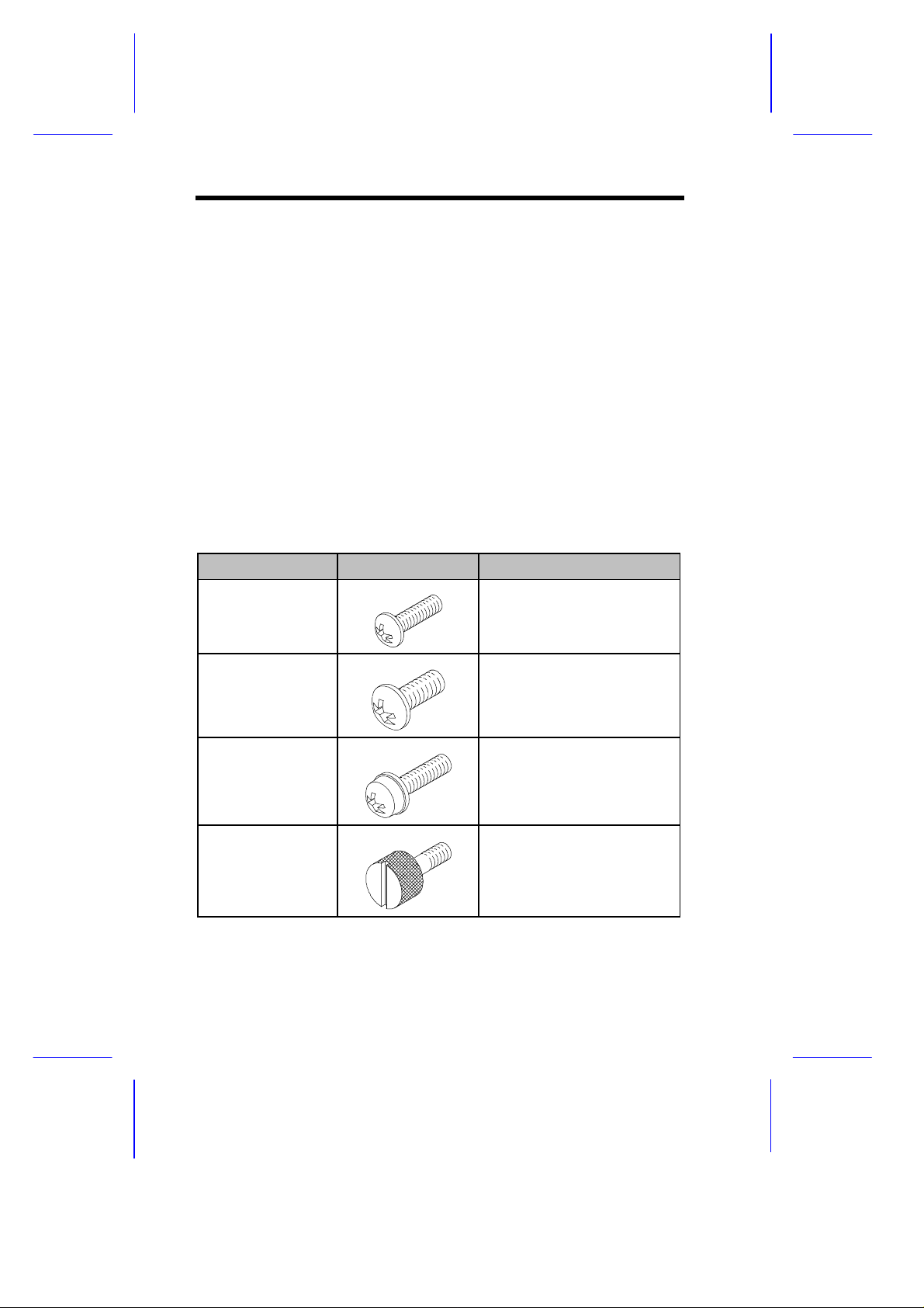
1.3 Screw Types Used
The following screws are used in the assembly of the Acer Altos
RM900 and other rack-mountable components:
Screw Type Figure Usage
M4 metal screw
M5 metal screw
M6 washer-face
metal screw
M6 thumbscrew
2
Securing the component
rail to the mounting rail.
See section 8.1
Securing the system
components and the
mounting brackets to the
rack
Securing the system
components to the rack
Securing the server
system to the rack (for
Acer Altos 1100 server)
Page 3
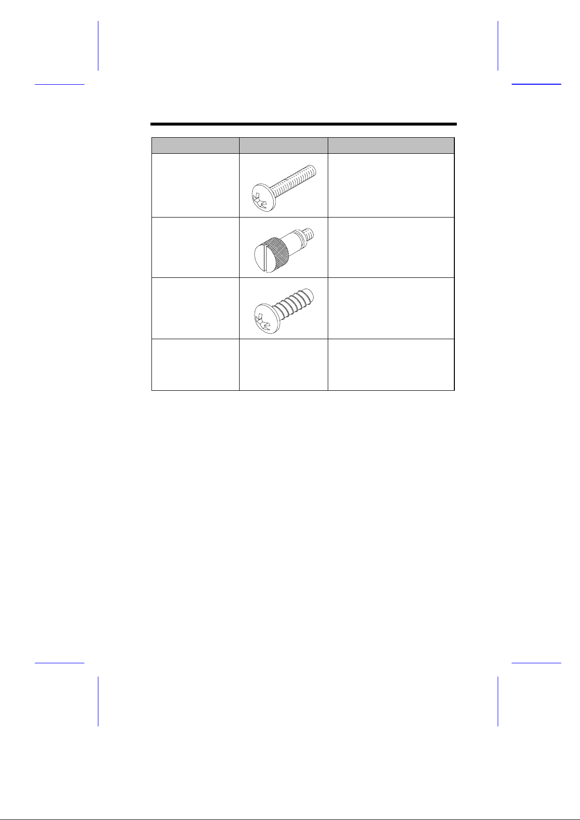
Screw Type Figure Usage
#6-32 screw
#6-32
thumbscrew
M5 metal tapping
screw
Cage Nut
Installing the front panel to
the server system (for
Acer Altos 11000, 12000,
and 21000 server)
Securing the server and
front panel to the rack (for
Acer Altos 11000, 12000,
and 21000 server)
Securing the cable
bracket to the rack (comes
with the cable bracket
package)
Supports the M6 metal
screws for securing
system components to the
rack
3
Page 4
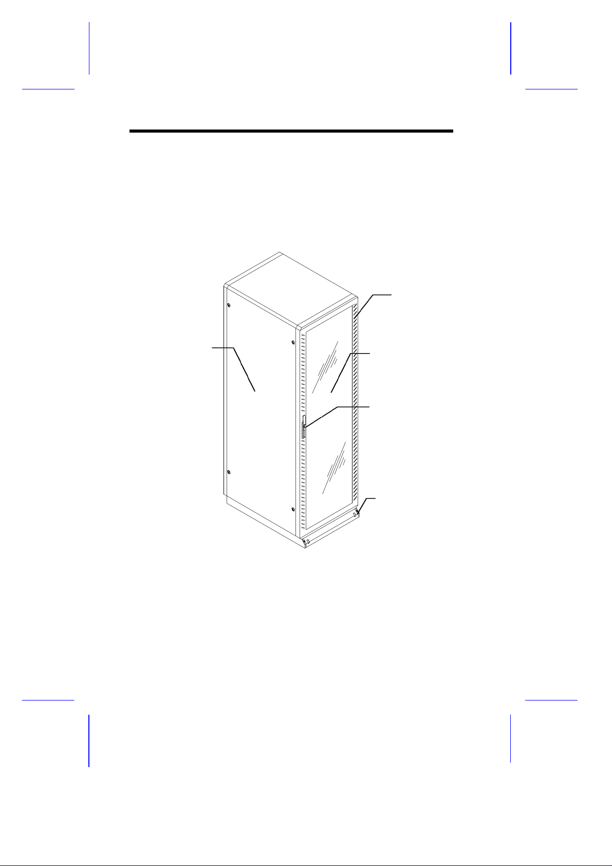
2 Features
Front Door
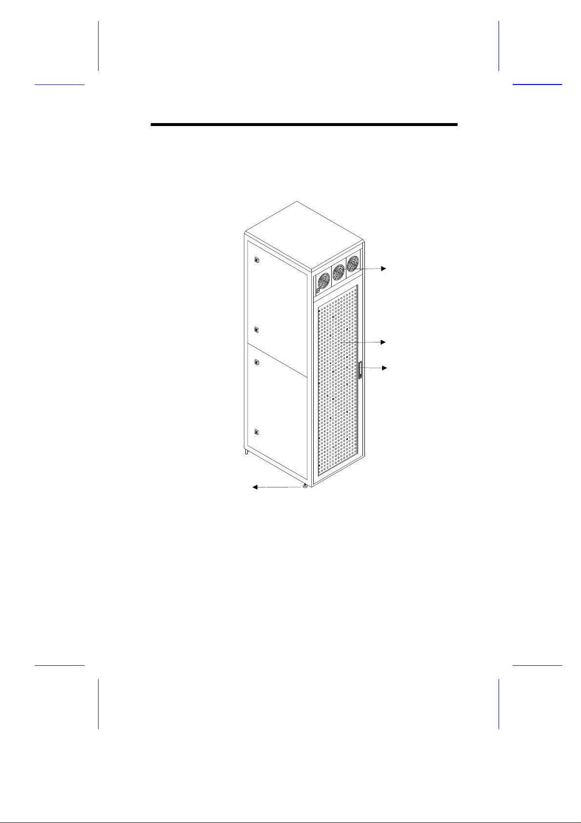
2.1 Front View
The following figure shows the front view of the Acer Altos RM900:
Vents
Side Panel
Handle with Lock
Stand and
Stabilizing Foot
Figure 1 The Acer Altos RM900 (42U Rack) - Front View
4
Page 5
2.2 Rear View
(beside caster)
The following figure shows the rear view of the Acer Altos RM900:
Fan
Rear door
Handle
Leveling foot
Figure 2 The Acer Altos RM900 (42U Rack) - Rear View
5
Page 6
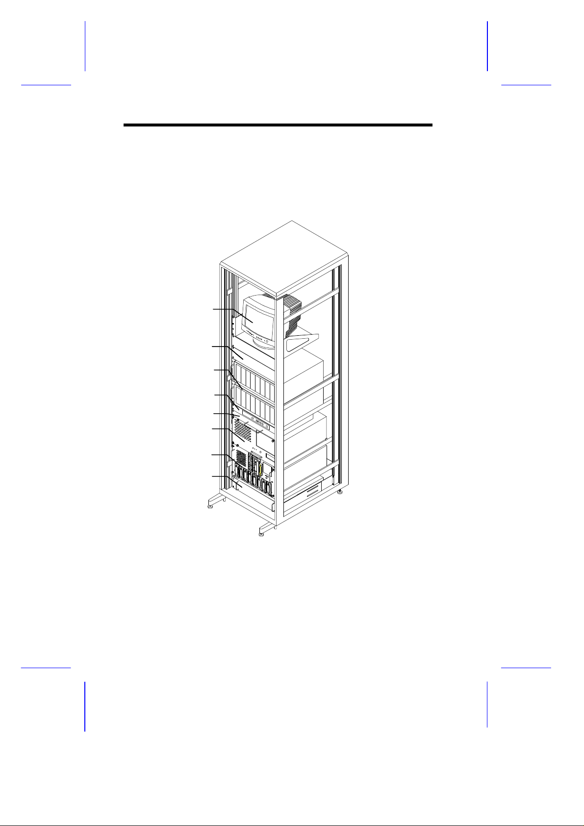
2.3 Inside Components
The following figure shows the different components that can be
installed in the Acer Altos RM900:
Monitor
Blanking panelBlanking panel
Storage subsystems
Switchbox
Keyboard/touchpad
with sliding shelf
Server
Server
UPS
Figure 3 A Typical Acer Altos RM900 Enclosure
6
Page 7
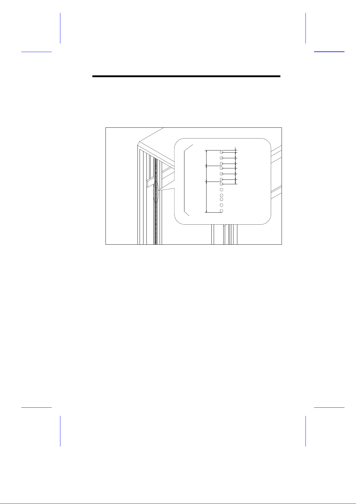
2.4 Vertical Mounting Hole Pattern
The four vertical rails of the Acer Altos RM900 contain square
mounting holes arranged in a manner shown in this figure:
0.25”
1U
1U
2U
Figure 4 Vertical Square Mounting Hole Spacing
0.625”
0.625
0.5”
0.625”
0.625”
0.5”
The distance from the center of two holes with closer spacing to the
center of the next pair is equivalent to 1U.
When installing components, you must start your measurement from
the center of the two holes with closer spacing. Otherwise, the screw
holes on the component may not match with those on the rack.
7
Page 8
3 Positioning the Rack
The rack comes with casters to help you move it easily from one
place to another.
To position the rack:
1. Allow the following minimum clearances:
For operation: Leave at least 46 cm (1.5 ft) of clearance in front
of the rack and 31 cm (1 ft) behind the rack to allow adequate
airflow.
For servicing: Allow 61 cm (2 ft) of space behind the rack and
165 cm (65 inches) in front of the rack.
2. After you have positioned the rack, locate the two stabilizing feet
and the two leveling feet placed just next to each caster. These
feet are used for support to ensure that the rack is stable and to
compensate for uneven floors when leveling the rack. See step
2 of Figure 5.
3. Pull out the two stabilizing feet. See step 3 of Figure 5.
4. Rotate each foot to adjust it. Continue adjusting the feet until the
rack is level. See step 4 of Figure 5.
Make sure the rack is stable.
8
Page 9
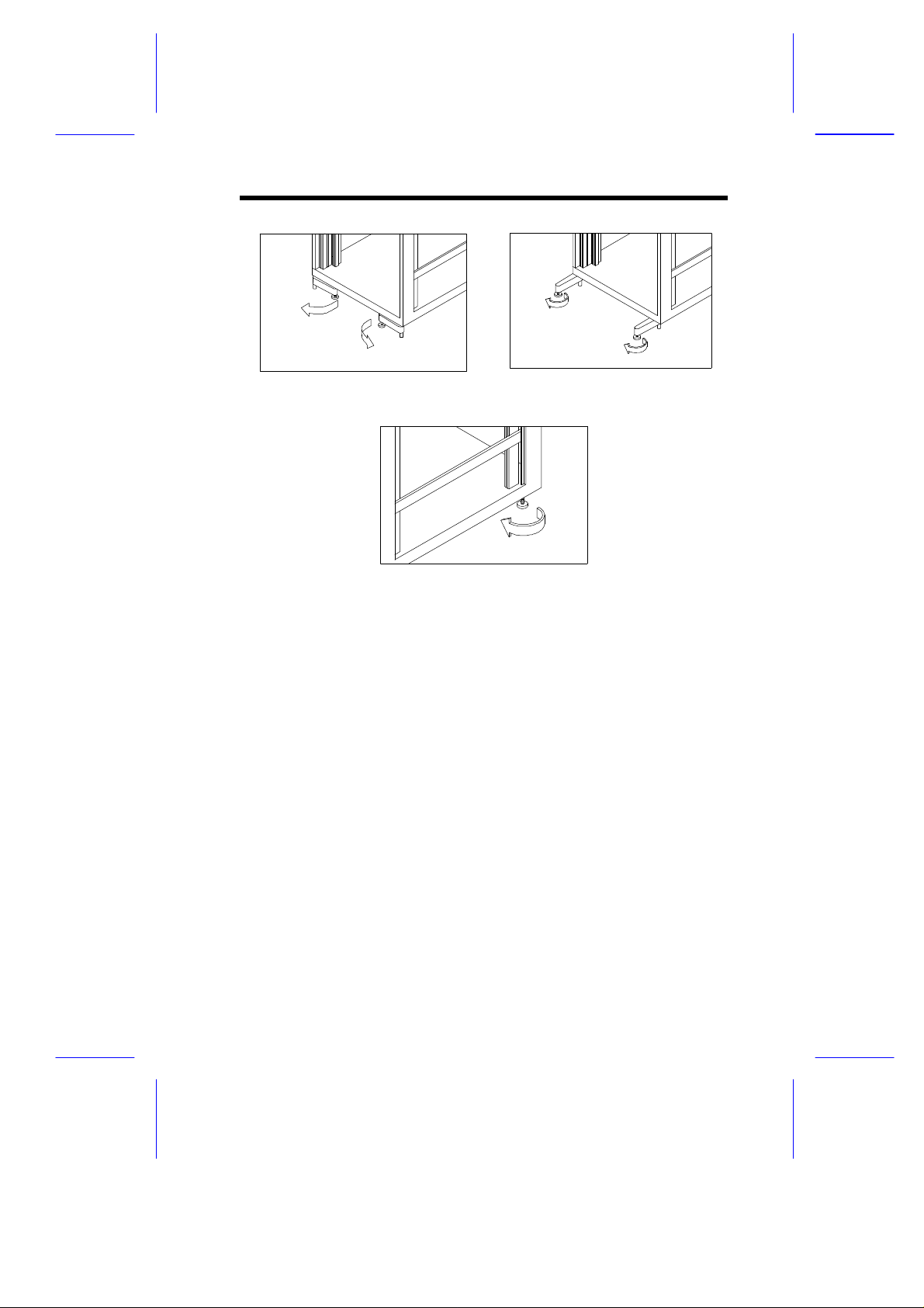
Step 2
Step 4
Figure 5 Adjusting the Rack Feet
Step 3
9
Page 10
4 Opening and Closing the Door
The rack has one front door and one rear door. Both doors are
vented and can be opened easily.
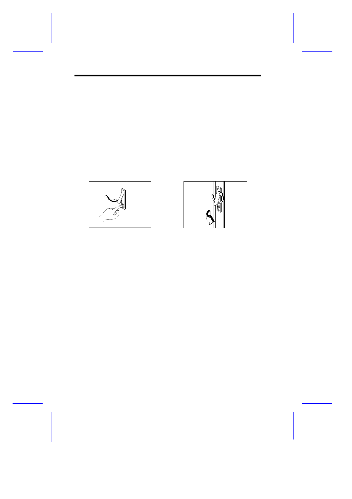
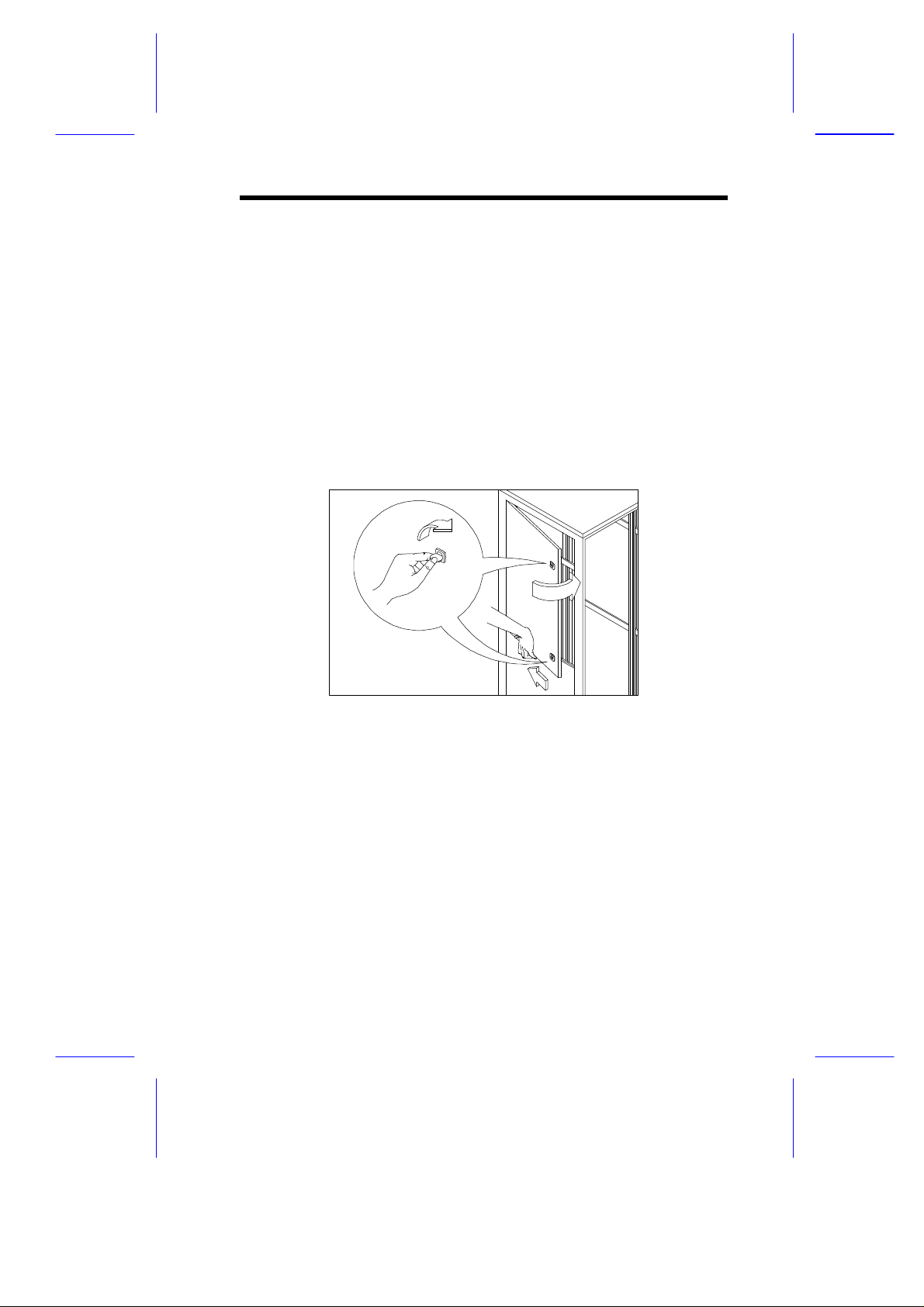
To open the rack's front or rear door:
1. Slide the keylock cover as far as it will go, press the keylock
button to automatically release the handle. If the door is locked,
unlock it using the key.
2. Rotate the handle 90 degrees counter-clockwise until the latch
releases, and then pull open the door.
Step 1
Figure 6 Opening the Rack Door
To close the rack's front or rear door:
1. Shut the door and rotate the handle clockwise to its original
position.
2. Push the handle until it clicks.
10
Step 2
Page 11
5 Removing and Reinstalling the Door
Step 4
You may need to remove the front and rear doors when installing
components into the rack or when servicing.
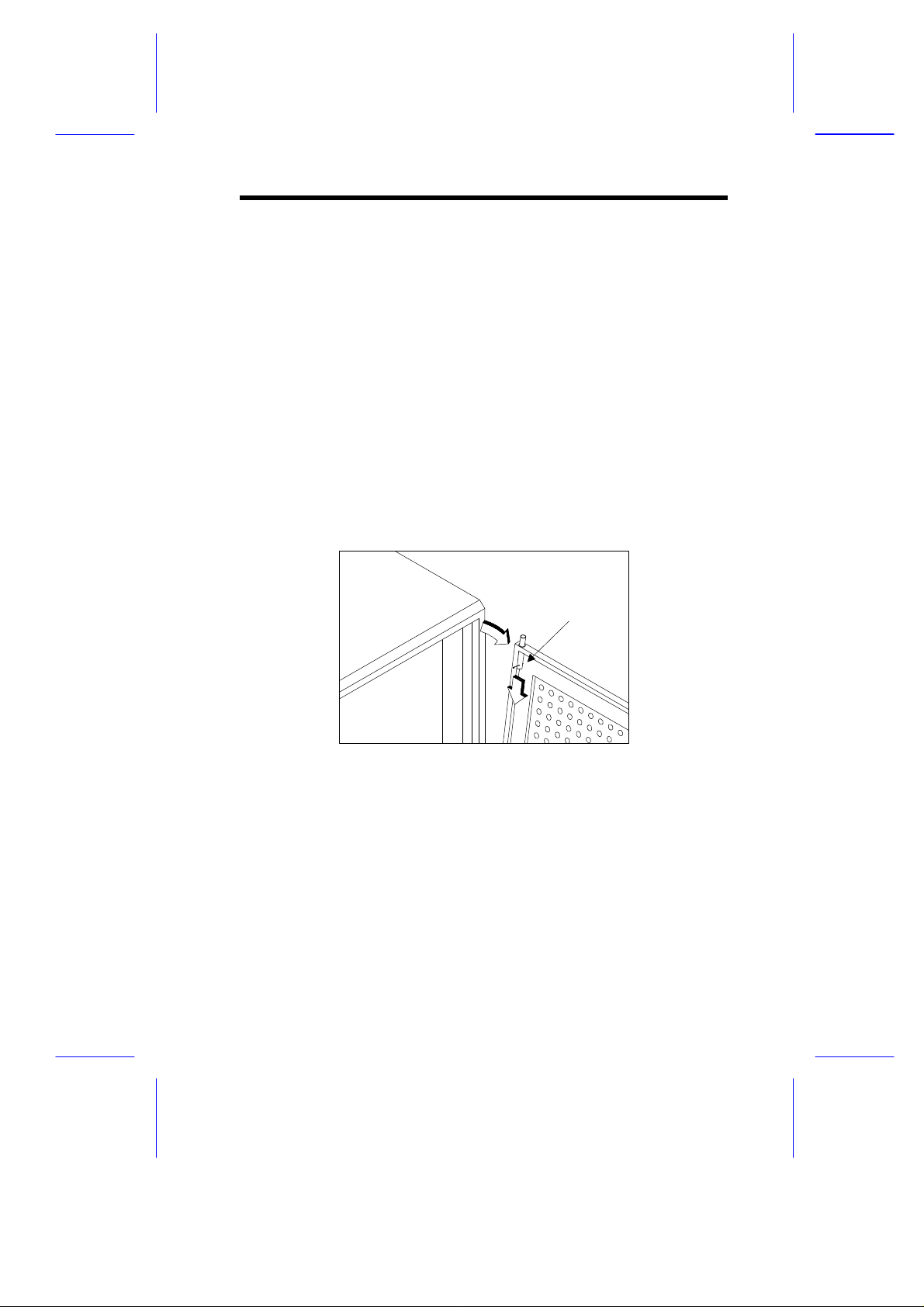
To remove the front or rear door:
1. Open the door. See section 4.
2. Locate the release lever in the upper-right corner of the front
door or in the upper-left corner of the rear door.
3. Using your finger, pull down the release lever. This releases the
upper door holder.
4. When the upper holder is released, slightly lift the door to
remove the lower holder from its slot.
Release lever
Step 3
Figure 7 Removing the Rack Door
To reinstall the front or rear door:
1. Place the lower holder into its slot.
2. Using your finger, pull down the release lever while fitting the
upper holder into its slot.
11
Page 12
6 Removing and Replacing the Side
B2
C
Panels
The rack comes with 4 side panels. When installing components or
when servicing, you may need to remove all side panels for quick and
easy access to the components.
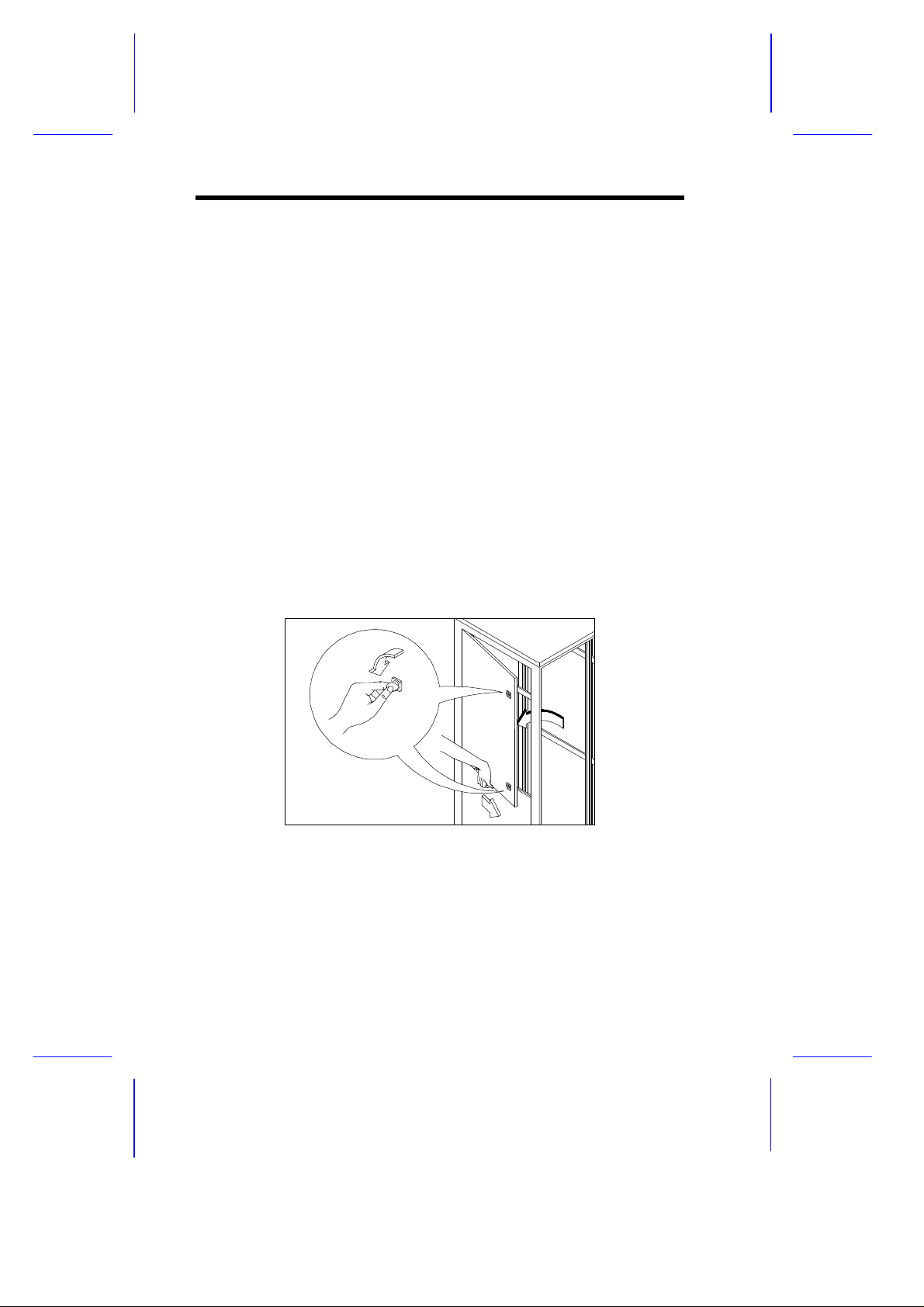
To remove the side panels:
1. Each side panel has two screws. Using a coin or any flat-head
tool, rotate each screw 90 degrees clockwise (for the right
panels) or counter-clockwise (for the left panels) to release the
side panel. See A of Figure 8.
2. Use one hand to push the side panel (see B1 of Figure 8) and
another hand to support it at the bottom (see B2 of Figure 8).
3. When the side panel is released, pull it out to totally detach it
from the rack. Repeat the steps until all side panels are
removed. See C of Figure 8.
A
Figure 8 Removing the Side Panel
12
B1
Page 13
To replace the side panels:
B
C
1. Locate the side of the panel that does not contain the screws.
2. Align the groove on that side of the panel with the edge of the
rack, then insert it. See A of Figure 9.
3. Push the other side until it is completely inserted. See B of
Figure 9.
4. Using a coin or any flat-head tool, rotate the two screws on the
panel 90 degrees counter-clockwise (for the right panels) or
clockwise (for the left panels) to secure the panel to the rack.
See C of Figure 9.
Figure 9 Replacing the Side Panel
A
13
Page 14

7
the Rack
The following sections include instructions for installing UPS, server
monitors.
7.1
Cage nuts are use to secure systems and other components to the
vertical rails in the rack.
1.
at the back of a rail.
2. Insert the small end of the cage-nut installation tool through the
opening in the rail and hook the tool over the top lip of the cage
3.
back toward you until the top lip of the cage nut snaps into
position.
Repeat this process to install the other cage nuts in the
7.2 Loading an APC Uninterrupted Power Supply
The UPS protects the equipment from being damaged due to power
fluctuations. Since the UPS is extremely heavy, it should always be
14
Page 15
To load an APC UPS:
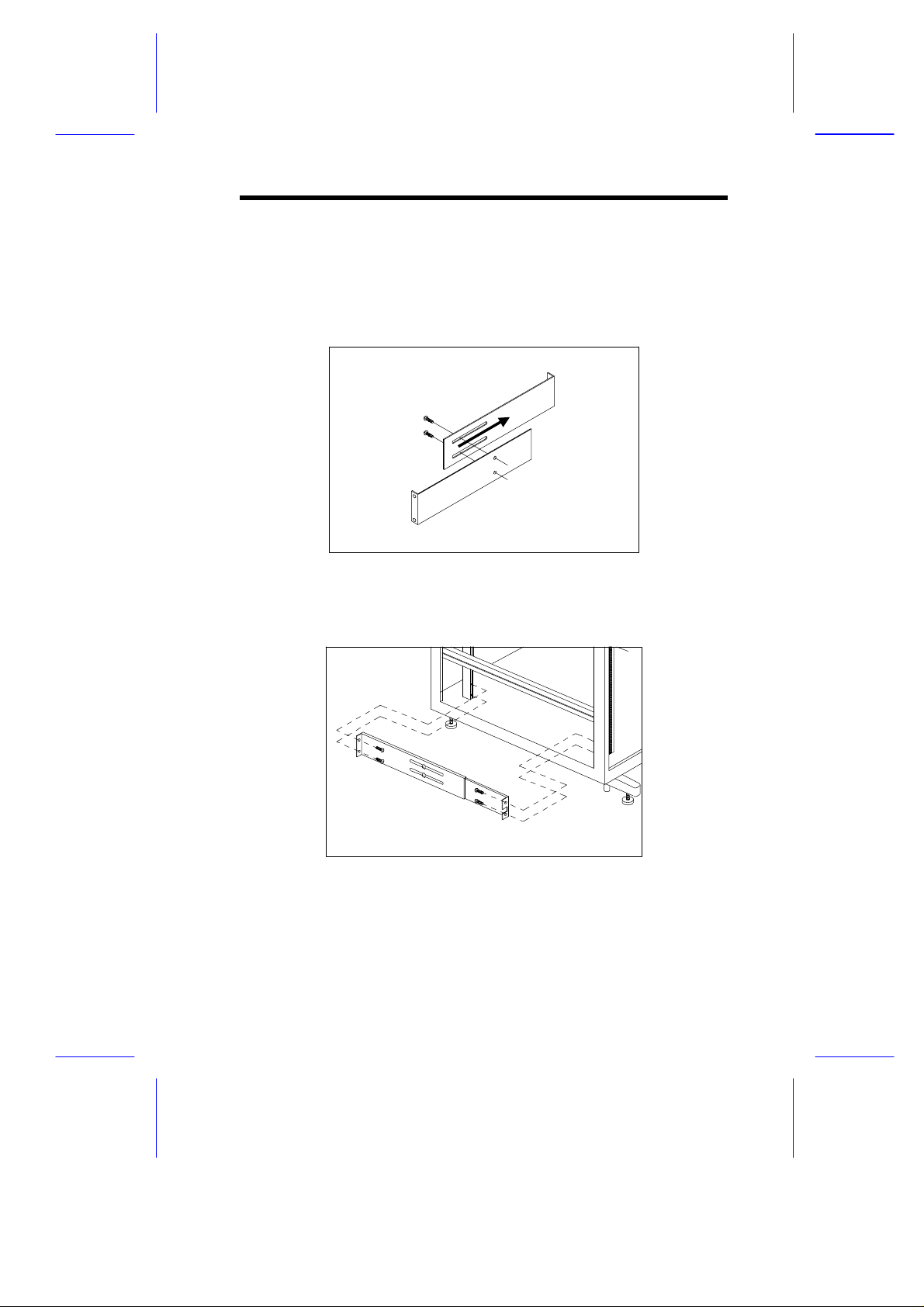
1. Unpack the mounting brackets that came with the APC UPS.
2. Adjust the mounting brackets to fit into the rack and then use two
M4 screws to afix them.
Figure 10 Adjusting the Mounting Brackets
1. Attach the mounting brackets to the rack using four M5 screws.
Figure 11 Attaching the Mounting Brackets to the Rack
4. Load the APC UPS into the rack.
15
Page 16
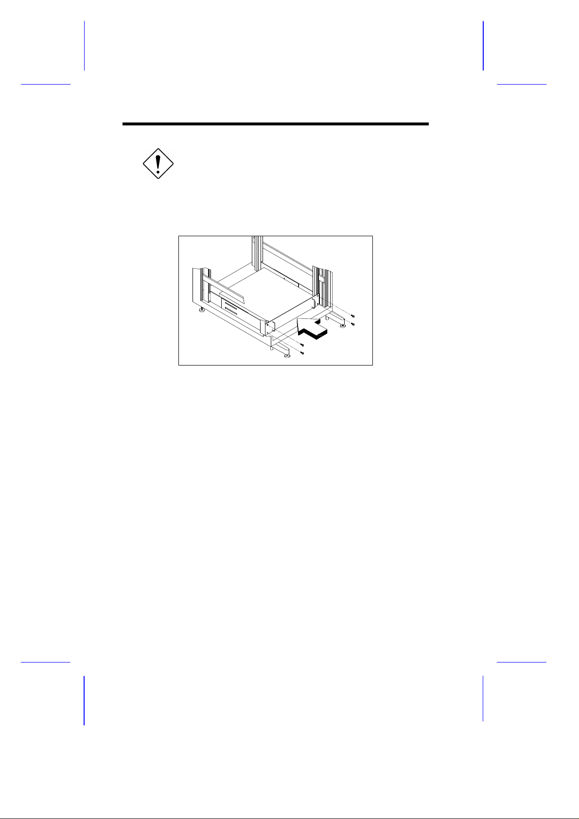
To avoid damage to the equipment or personal
injury, load the APC UPS at the bottom of the
rack only.
5. Secure the APC UPS at the front with four M5 washer-face
screws.
Figure 12 Loading the APC UPS
16
Page 17

7.3 Loading an Acer Altos 1100 Server
latch
component rail
7.3.1 Installing the Mounting Rails
The rails allow the system to slide in and out of the rackmount for
maintenance purposes. Follow these steps to install the mounting
rails:
1. Extend the component rails from the mounting rails until the
component rail release latches click. Then hold down the latches
and slip the component rails out of the mounting rails. See
Figure 13.
mounting rail
Figure 13 Removing the Component Rail from the Mounting Rail
(for Acer Altos 1100 Server)
2. Put the component rails to one side.
3. Attach the mounting rails to the mounting brackets:
i. Notice that each mounting rail consists of:
• a fixed outer piece that screws into the mounting
bracket
• an inner sliding piece controlled by a steel ball gearing
movement. This inner sliding piece is not detachable.
17
Page 18

ii. Align the screw holes on the mounting bracket and the
and v
mounting rail.
iii. Extend the inner sliding piece of the mounting rail.
iv. Align the three holes on the mounting rail with the holes on
the mounting bracket.
v. Fasten the mounting rail to the mounting bracket with three
M5 screws. See Figure 14.
steps iv
mounting
bracket
step iii
mounting rail
Figure 14 Aligning and Fastening the Mounting Rail to the
Mounting Bracket (for Acer Altos 1100 Server)
vi. Adjust the inner sliding piece to align the two holes on the
other end of the mounting bracket with the mounting rail. To
adjust the inner sliding piece, press the latch located at the
end of it and then push back the inner sliding piece. You can
only align one hole at a time. Continue moving the inner
sliding piece until you align one of the holes. See Figure 15.
Be careful when pressing the latch. Use a
screwdriver or any similar tool.
18
Page 19

piece
mounting
bracket
A
inner sliding
latch
Figure 15 Adjusting the Inner Sliding Piece to Align the Holes
(for Acer Altos 1100 Server)
vii. When you have aligned one of the holes, then insert one M5
screw into it. See A of Figure 16.
viii. Adjust the inner sliding piece until you align the other hole on
the end part of the mounting bracket, then insert one M5
screw. This securely fastens the mounting rail to the
mounting bracket. See B of Figure 16.
mounting bracket
inner sliding piece
hole
mounting rail
19
Page 20

mounting bracket
B
hole
mounting
rail
inner sliding
piece
Figure 16 Aligning the Bracket Hole and Fastening the Mounting
Rail to the Mounting Bracket (for Acer Altos 1100
Server)
5. Attach the mounting brackets with rail to the rack using four M5
screws. Make sure that the holes on the mounting brackets are
aligned with the holes on the rack. See the following figure:
Figure 17 Attaching the Mounting Brackets to the Rack (for Acer
Altos 1100 Server)
20
Page 21

The Acer Altos 1100 server occupies 6U. Count the U positions and
hole numbers from the bottom up. Secure the mounting bracket on
the 1st and the 3rd holes of the 1st U using two M5 screws. Make sure
that both of the mounting brackets are at the same level.
Take note of the vertical rail hole pattern. For
more information on the vertical rail hole pattern
and spacing, see section 2.4.
7.3.2 Installing the Component Rails
The component rails align the system housing to the mounting rail.
For more information about the mounting rail, please refer to section
7.3.1.
1. Attach the handle to the drawer using two M5 screws. See the
figure below.
Figure 18 Attaching the Handle to the Drawer
21
Page 22

2. Attach a component rail on each side of the drawer with five M5
screws. See the following figure:
Figure 19 Attaching Component Rails to the Drawer
3. Load the server on the drawer.
i. Check the stand-off brackets that came with your Acer Altos
1100 server rackmount kit. Each stand-off bracket is marked
as follows:
REAR-L
Figure 20 Stand-off Brackets
22
REAR-R
FRONT-L
FRONT-R
Page 23

ii. Attach the stand-off brackets to the drawer using M5
FRONT-L
FRONT-R
screws.
REAR-L
REAR-R
Figure 21 Attaching the Stand-off Brackets to the Drawer
iii. Remove the original front panel of the Acer Altos server.
Refer to your server manual for instructions on how to
remove the original front panel.
iv. Place the server on the drawer and secure it to the drawer
and brackets using four M5 screws.
Figure 22 Securing the Server to the Drawer
23
Page 24

7.3.3 Installing the Acer Altos Server into the Acer Altos
RM900
You may need to apply some pressure the first
time you slide the component into the rack.
After some time, the ball bearings in the slide
will move easily.
1. Extend the inner sliding piece of the mounting rails forward until it
clicks.
Figure 23 Extending the Inner Sliding Piece (For Acer Altos
1100 Server)
2. Carefully align the drawer's component rails with the mounting
bracket's rail, then push the drawer into the rack until it clicks.
3. Depress the component rail release latch on either side of the
drawer, then slide the drawer into the rack.
To avoid personal injury, care should be taken
when pressing the component rail release
latches and sliding the component into the rack.
24
Page 25

Figure 24 Loading the Acer Altos 1100 Server
AB C
A
4. Remove the two screws on the upper edge of the server. See A
of Figure 25.
5. Cut the clip that holds the handle on the upper edge of the server.
See B of Figure 25.
6. Depress the handle. See C of Figure 25.
Figure 25 Removing the Screws and Clip and Depressing the
Handle
25
Page 26

7. Attach the front panel that came with the rackmount kit to the
server. See the following figure:
Figure 26 Attaching the Front Panel (For Acer Altos 1100
Server)
8. Attach the cable carrier. The cable carrier allows you to tie-wrap
all cables to and from the server. As you slide the server in and
out of the rack, the cable carrier collapses and extends, keeping
the cables untangled and attached to the server.
To attach the cable carrier:
i. Attach one end of the cable carrier to the drawer using two
M5 screws. See step i of Figure 27.
ii. Install two cage nuts on the inside of the rack and then
attach the other end of the cable carrier on the outside of
the rear brace opposite the cage nuts with two M5 screws.
See step ii of Figure 27. See section 7.1 for the installation
of the cage nuts.
26
Page 27

step i
step ii
Figure 27 Attaching the Cable Carrier (For Acer Altos 1100
Server)
iii. Extend the cable carrier.
iv. Bundle all cables to the cable carrier with cable clamps. See
Figure 28.
v. Route all cables from the cable carrier to the cable
management bracket located on the rear of the rack. For
details on cabling, refer to section 7.6.3 - Cabling the Switch
Box and section 7.6.4 - Completing the Cabling.
Figure 28 Bundling the Cable using the Cable Clamps (For Acer
Altos 1100 Server)
27
Page 28

9. Secure the server to the rack using four M5 thumbscrews.
Figure 29 Securing the Acer Altos 1100 Server to the Rack
28
Page 29

7.4 Loading an Acer Altos 11000, 12000, or 21000
component rail
Server
7.4.1 Installing the Mounting Rails
The rails allow the system to slide in and out of the rackmount for
maintenance purposes. Follow these steps to install the mounting
rails:
1. Extend the component rails from the mounting rails until the
component rail release latches click. Then hold down the latches
and slip the component rails out of the mounting rails. See
Figure 30.
latch
Figure 30 Removing the Component Rail from the Mounting Rail
(for Acer Altos 11000, 12000, or 21000)
2. Put the component rails to one side.
3. Attach each mounting rail to the mounting bracket:
i. Notice that the mounting rail consists of:
• a fixed outer piece that screws into the mounting
bracket
• an inner sliding piece controlled by a steel ball gearing
movement. This inner sliding piece is not detachable.
mounting rail
29
Page 30

ii. Align the screw holes on the mounting bracket and the
and v
mounting rail.
iii. Extend the inner sliding piece of the mounting rail.
iv. Align the two holes on the mounting rail with the holes on the
mounting bracket.
v. Fasten the mounting rail to the mounting bracket with two M5
screws. See Figure 31.
mounting
bracket
Follow the path of the
arrows when installing
the mounting rail to the
mounting bracket
mounting rail
steps iv
step iii
Left Right
Figure 31 Aligning and Fastening the Mounting Rail to the
Mounting Bracket (for Acer Altos 11000, 12000, or
21000)
vi. Adjust the inner sliding piece to align the two holes on the
other end of the mounting bracket with the mounting rail. To
adjust the inner sliding piece, press the latch located at the
end of it and then push back the inner sliding piece. You can
only align one hole at a time. Continue moving the inner
sliding piece until you align one of the holes. See Figure 32.
Be careful when pressing the latch. Use a
screwdriver or any similar tool.
30
Page 31

piece
mounting
bracket
A
latch
inner sliding
Figure 32 Adjusting the Inner Sliding Piece to Align the Holes
(for Acer Altos 11000, 12000, or 21000)
vii. When you have aligned one of the holes, then insert one M5
screw into it. See A of Figure 33.
viii. Adjust the inner sliding piece until you align the other hole on
the middle part of the mounting bracket, then insert one M5
screw. See B of Figure 33.
ix. Adjust the inner sliding piece again until you align the last
hole on the end part of the mounting bracket, then insert one
M5 screw. This securely fastens the mounting rail to the
mounting bracket. See C of Figure 33.
mounting bracket
inner sliding piece
mounting rail
hole
31
Page 32

mounting bracket
inner sliding piece
B
hole
mounting bracket
inner sliding piece
C
hole
Figure 33 Aligning the Bracket Hole and Fastening the Mounting
Rail to the Mounting Bracket (for Acer Altos 11000,
12000, or 21000)
mounting rail
mounting rail
32
Page 33

5. Attach the mounting bracket with rail to the rack using four M5
screws. Make sure that the holes on the mounting bracket are
aligned with the holes on the rack. See the following figure:
Figure 34 Attaching the Mounting Bracket to the Rack (for Acer
Altos 11000, 12000, or 21000)
The Acer Altos 11000, 12000, and 21000 servers occupies 7U. Count
the U positions and hole numbers from the bottom up. Secure the
mounting bracket on the 2nd and 3rd holes of the 1st U and the 1st hole
of the 2nd U using four M5 screws. Make sure that both of the
mounting brackets are at the same level.
Take note of the vertical rail hole pattern. For
more information on the vertical rail hole pattern
and spacing, see section 2.4.
7.4.2 Installing the Component Rails
To install the component rails:
1. Insert the key into the lock and turn it clockwise until it points to
the unlocked icon.
2. Open it to more than a 45° angle.
33
Page 34

3. Lift it up a little and then move it away from the server.
Figure 35 Removing the Front Bezel
4. Remove the lock bracket.
Figure 36 Removing the Lock Bracket
5. Replace the front metal cover with the one supplied in the
rackmount kit or rearrange the LCD Display module.
34
Page 35

For Acer Altos 11000 or 12000
Remove the screw from the metal cover and replace the metal
cover using the same screw.
Figure 37 Replacing the Metal Cover with the Rackmount Kit
Cover
For Acer Altos 21000
The front panel of the Acer Altos 21000 has an LCD display
module installed. Simply rearrange the position of the LCD
display module as shown below.
Figure 38 Rearranging the LCD Display Module
6. Place the server side ways on a steady surface with the support
panel facing up.
7. Remove the screw located at the back of the server and then
gently pull back and lift up the support panel to detached.
35
Page 36

Figure 39 Removing the Support Panel
8. Remove the remaining wheels and keep the screws and the
wheels in a safe place for future use.
Figure 40 Removing the Wheels
36
Page 37

9. Attach the component rails to the server with ten M4 screws.
Figure 41 Attaching Component Rails to the server
10. Attach the cable carrier bracket to the server with two M4 screws.
Figure 42 Attaching the Cable Carrier Bracket to the Server
37
Page 38

11. Attach the front panel that came with the rackmount kit to the
server using six #6-32 screws. See the following figure:
Figure 43 Attaching the Front Panel (for Acer Altos 11000,
12000, or 21000)
7.4.3 Installing the Acer Altos Server into the Acer Altos
RM900
You may need to apply some pressure the first
time you slide the component into the rack.
After some time, the ball bearings in the slide
will move easily.
38
Page 39

1. Extend the inner sliding piece of each mounting rail forward until
it clicks.
Figure 44 Extending the Inner Sliding Pieces
2. Carefully align the server’s rails with the mounting bracket's rail,
and then push the server into the rack until it clicks.
3. Depress the component rail release latch on either side of the
drawer and then slide the drawer into the rack.
To avoid personal injury, care should be taken
when pressing the component rail release
latches and sliding the component into the rack.
39
Page 40

Figure 45 Loading the Acer Altos 11000, 12000, or 21000
Server
4. Attach the cable carrier. The cable carrier allows you to tie-wrap
all cables to and from the server. As you slide the server in and
out of the rack, the cable carrier collapses and extends, keeping
the cables untangled and attached to the server.
To attach the cable carrier:
i. Attach one end of the cable carrier to the server using two
M5 screws. See step i of Figure 46.
ii. Install two cage nuts on the inside of the rack and then
attach the other end of the cable carrier on the outside of the
rear brace opposite the cage nuts with two M5 screws. See
step ii of Figure 46. See section 7.1 for the installation of the
cage nuts.
step i
step ii
Figure 46 Attaching the Cable Carrier (for Acer Altos 11000,
12000, or 21000)
iii. Extend the cable carrier.
iv. Bundle all cables to the cable carrier with cable clamps. See
Figure 47.
40
Page 41

v. Route all cables from the cable carrier to the cable
management bracket located on the rear of the rack. For
details on cabling, refer to section 7.6.3 - Cabling the Switch
Box and section 7.6.4 - Completing the Cabling.
Figure 47 Bundling the Cable using the Cable Clamps (for Acer
Altos 11000, 12000, or 21000)
9. Secure the server to the rack using four M5 thumbscrews.
Figure 48 Securing the Acer Altos 11000, 12000, or 21000
Server to the Rack
41
Page 42

7.5 Loading an Acer Altos RS700-RM101/102 into
the Acer Altos RM900
The Acer Altos RS700-RM101/102 storage subsystem enclosure
occupies 4U in the Acer Altos RM900. Count the U positions and
hole numbers from the bottom up.
To install the RS700-RM101/102 into the rack:
1. Locate an unoccupied spot in the rack.
2. Secure the angular steel bars on the 2nd and 3rd holes of the 2nd U
using four M5 screws. Please refer to the previous section for
more information. Make sure that both of the angular bars are at
the same level.
Figure 49 Attaching the Angular Bars to the Rack (for Acer Altos
RS700)
42
Page 43

3. Install four cage nuts on the inside of the rail (see section 7.1) and
Support Bar
slide in the RS700-RM101/102 storage subsystem enclosure.
Secure it with four M5 screws as shown below.
Figure 50 Securing the Acer Altos RS700-RM101/102 Storage
Subsystem Enclosure to the Rack
When you slide in the enclosure make sure
that the lower part of the support bar is
resting on the angular bar.
43
Page 44

7.6 Loading a Keyboard/Mouse/Monitor Switch
Box
To load the switch box:
1. Extend the cable support bracket on the rear of the switch box.
Refer to the switch box’s manual for detailed instructions.
2. Install four cage nuts on the inside of the rail (see section 7.1) and
then align the switch rack with the cage nuts. Secure it with four
M5 washer-face screws. See the following figure:
Figure 51 Loading the Switch Box
Take note of the vertical rail hole pattern. For
more information on the vertical rail hole pattern
and spacing, see section 2.4.
44
Page 45

7.6.1 Loading a Keyboard
To load a keyboard:
1. Insert the keyboard shelf into the rack.
2. Install four cage nuts on the inside of the rail (see section 7.1)
and then align the keyboard shelf to the cage nuts. Secure it
with four M5 washer-face screws.
3. For cabling details, refer to section 7.6.3 - Cabling the Switch
Box and section 7.6.4 - Completing the Cabling.
Figure 52 Loading the Keyboard Shelf
Take note of the vertical rail hole pattern. For
more information on the vertical rail hole pattern
and spacing, see section 2.4.
45
Page 46

7.6.2 Loading a Monitor
To load a monitor:
1. Before you start, check the height of your monitor. Make sure
that it will fit into the desired location in the rack.
2. Insert the monitor shelf into the rack.
3. Install eight cage nuts on the inside of the rail (see section 7.1)
and then align the monitor shelf to the cage nuts. Secure it with
eight M5 washer-face screws.
Figure 53 Attaching the Monitor Shelf
Take note of the vertical rail hole pattern. For
more information on the vertical rail hole pattern
and spacing, see section 2.4.
46
Page 47

4. Load the monitor into the rack.
Figure 54 Loading the Monitor
5. Plug the power cable into the monitor.
47
Page 48

6. Route the cables from the monitor to the cable management
bracket located on the rear of the rack. For cabling details, refer
to section 7.6.3 - Cabling the Switch Box and section 7.6.4 -
Completing the Cabling.
Figure 55 Cabling the Monitor
48
Page 49

7.6.3 Cabling the Switch Box
Before you proceed, make sure that the server
and all peripherals are turned off.
To connect the components to the switch box:
1. Plug the monitor and keyboard cables into the ports marked VGA
monitor, PS/2 or AT keyboard, and PS/2 mouse on the switch
box, respectively. Refer to Figure 50.
The keyboard/touchpad cable has two
connectors: one for keyboard and one for
mouse. The keyboard connector is marked with
a keyboard icon ( ), while the mouse
connector is marked with a mouse icon ( ).
2. Using the switch box cable, attach the 25-pin connector to any
25-pin port on the switch box back panel. Refer to Figure 54.
3. Plug the cable's video, keyboard, and mouse connectors into
their corresponding ports on the server. Refer to Figure 54.
Figure 56 Cabling the Switch Box
For details on how to operate the switch box,
refer to the manual that came with your switch
box.
49
Page 50

8 Completing the Cabling
The cable management brackets helps you organize the wires and
cables dangling inside the rack.
To install a cable management backet:
1. Install a cage nut on the outside of the rail.
2. Attach the support bracket to the cable management bracket and
then align it with the cage nut. Secure it with an M5 screw.
To arrange the cabling inside the rack:
1. Connect any remaining cables such as network cables, SCSI
cables, etc.
2. Route all cables to the cable management bracket located on the
left column of the rack. The cable management brackets are
designed to hold bundles of cables.
Cable
management
brackets
Figure 57 Cable Management Brackets Location
50
Page 51

9 Attaching the Blanking Panels
The rack may come with a blanking kit that includes three blanking
panels: one 1U, one 2U, and one 3U. You may need to install these
blanking panels to fill the empty spaces at the front of the rack.
To attach a blanking panel:
1. Place the blanking panel across the front vertical rails of the rack
and indicate the positions of the cage nuts.
2. Install four cage nuts on the inside of the rail (see section 7.1)
and then align the blanking panel to the cage nuts. Secure the
blanking panel with four M5 washer-face screws.
Figure 58 Attaching Blanking Panels
51
Page 52

10 Completing the Rack Component
Installation
After you have installed all the necessary components into the rack
and arranged the cabling, you need to replace the side panels, the
rear door, and the front door to complete the installation. For
instructions on how to replace side panels, refer to section 6 -
Removing and Replacing the Side Panels. For instructions on how to
replace the rear and front doors, refer to section 5 - Removing and
Replacing the Door.
52
 Loading...