

Page 1

Acer Altos R520 M2 Series
User’s Guide
Page 2

Copyright © 2009
All Rights Reserved.
Acer Altos R520 M2 Series
User’s Guide
Model Name : Acer Altos R520 M2
Part Number:
Purchase Date:
Place of Purchase:
Page 3

iii
Information for your safety and comfort
Visit http://registration.acer.com and discover the benefits of being an Acer
customer.
Safety instructions
Read these instructions carefully. Keep this document for future reference.
Follow all warnings and instructions marked on the product.
Turning the product off before cleaning
Unplug this product from the wall outlet before cleaning. Do not use liquid
cleaners or aerosol cleaners. Use a damp cloth for cleaning.
CAUTION for plug as disconnecting device
Observe the following guidelines when connecting and disconnecting power to
the power supply unit:
Install the power supply unit before connecting the power cord to the AC
power outlet.
Unplug the power cord before removing the power supply unit from the
computer.
If the system has multiple sources of power, disconnect power from the system
by unplugging all power cords from the power supplies.
CAUTION for accessibility
Be sure that the power outlet you plug the power cord into is easily accessible
and located as close to the equipment operator as possible. When you need to
disconnect power to the equipment, be sure to unplug the power cord from the
electrical outlet.
Warnings
• Do not use this product near water.
• Do not place this product on an unstable cart, stand or table. If the product
falls, it could be seriously damaged.
Page 4

iv
• Slots and openings are provided for ventilation to ensure reliable
operation of the product and to protect it from overheating. These
openings must not be blocked or covered. The openings should never be
blocked by placing the product on a bed, sofa, rug or other similar surface.
This product should never be placed near or over a radiator or heat
register, or in a built-in installation unless proper ventilation is provided.
• Never push objects of any kind into this product through cabinet slots as
they may touch dangerous voltage points or short-out parts that could
result in a fire or electric shock. Never spill liquid of any kind onto or into
the product.
• To avoid damage of internal components and to prevent battery leakage,
do not place the product on a vibrating surface.
• Never use it under sporting, exercising, or any vibrating environment
which will probably cause unexpected short current or damage rotor
devices, HDD, Optical drive, and even exposure risk from lithium battery
pack.
Using electrical power
• This product should be operated from the type of power indicated on the
marking label. If you are not sure of the type of power available, consult
your dealer or local power company.
• Do not allow anything to rest on the power cord. Do not locate this
product where people will walk on the cord.
• If an extension cord is used with this product, make sure that the total
ampere rating of the equipment plugged into the extension cord does not
exceed the extension cord ampere rating. Also, make sure that the total
rating of all products plugged into the wall outlet does not exceed the fuse
rating.
• Do not overload a power outlet, strip or receptacle by plugging in too
many devices. The overall system load must not exceed 80% of the branch
circuit rating. If power strips are used, the load should not exceed 80% of
the power strip's input rating.
• This product's power supply is equipped with a three-wire grounded plug.
The plug only fits in a grounded power outlet. Make sure the power outlet
is properly grounded before inserting the power supply plug. Do not insert
the plug into a non-grounded power outlet. Contact your electrician for
details.
Warning! The grounding pin is a safety feature. Using a power
outlet that is not properly grounded may result in electric shock
and/or injury.
Page 5

Note: The grounding pin also provides good protection from unexpected
noise produced by other nearby electrical devices that may interfere with
the performance of this product.
• Use the product only with the supplied power supply cord set. If you need
to replace the power cord set, make sure that the new power cord meets
the following requirements: detachable type, UL listed/CSA certified, VDE
approved or its equivalent, 4.6 meters (15 feet) maximum length.
Product servicing
Do not attempt to service this product yourself, as opening or removing covers
may expose you to dangerous voltage points or other risks. Refer all servicing to
qualified service personnel.
Unplug this product from the wall outlet and refer servicing to qualified service
personnel when:
• the power cord or plug is damaged, cut or frayed
• liquid was spilled into the product
• the product was exposed to rain or water
• the product has been dropped or the case has been damaged
• the product exhibits a distinct change in performance, indicating a need
for service
• the product does not operate normally after following the operating
instructions
v
Note: Adjust only those controls that are covered by the operating
instructions, since improper adjustment of other controls may result in
damage and will often require extensive work by a qualified technician to
restore the product to normal condition.
CAUTION: Danger of explosion if battery is incorrectly replaced. Replace only
with the same or equivalent type recommended by the manufacturer. Dispose
of used batteries according to the manufacturer’s instructions.
Page 6
vi
Additional safety information
Your device and its enhancements may contain small parts. Keep them out of
the reach of small children.
Disposal instructions
Do not throw this electronic device into the trash when discarding.
To minimize pollution and ensure utmost protection of the global environment,
please recycle. For more information on the Waste from Electrical and
Electronics Equipment (WEEE) regulations, visit
http://www.acer-group.com/public/Sustainability/sustainability01.htm.
Mercury advisory
For projectors or electronic products containing an LCD/CRT monitor or display:
Lamp(s) inside this product contain mercury and must be recycled or disposed of
according to local, state or federal laws. For more information, contact the
Electronic Industries Alliance at www.eiae.org
information, check www.lamprecycle.org
. For lamp-specific disposal
.
Page 7

vii
Tips and information for comfortable use
Computer users may complain of eyestrain and headaches after prolonged use.
Users are also at risk of physical injury after long hours of working in front of a
computer. Long work periods, bad posture, poor work habits, stress, inadequate
working conditions, personal health and other factors greatly increase the risk
of physical injury.
Incorrect computer usage may lead to carpal tunnel syndrome, tendonitis,
tenosynovitis or other musculoskeletal disorders. The following symptoms may
appear in the hands, wrists, arms, shoulders, neck or back:
• numbness, or a burning or tingling sensation
• aching, soreness or tenderness
• pain, swelling or throbbing
• stiffness or tightness
• coldness or weakness
If you have these symptoms, or any other recurring or persistent discomfort
and/or pain related to computer use, consult a physician immediately and
inform your company's health and safety department.
The following section provides tips for more comfortable computer use.
Finding your comfort zone
Find your comfort zone by adjusting the viewing angle of the monitor, using a
footrest, or raising your sitting height to achieve maximum comfort. Observe
the following tips:
• refrain from staying too long in one fixed posture
• avoid slouching forward and/or leaning backward
• stand up and walk around regularly to remove the strain on your leg
muscles
• take short rests to relax your neck and shoulders
• avoid tensing your muscles or shrugging your shoulders
• install the external display, keyboard and mouse properly and within
comfortable reach
• if you view your monitor more than your documents, place the display at
the center of your desk to minimize neck strain
Page 8

viii
Taking care of your vision
Long viewing hours, wearing incorrect glasses or contact lenses, glare, excessive
room lighting, poorly focused screens, very small typefaces and low-contrast
displays could stress your eyes. The following sections provide suggestions on
how to reduce eyestrain.
Eyes
• Rest your eyes frequently.
• Give your eyes regular breaks by looking away from the monitor and
focusing on a distant point.
• Blink frequently to keep your eyes from drying out.
Display
• Keep your display clean.
• Keep your head at a higher level than the top edge of the display so your
eyes point downward when looking at the middle of the display.
• Adjust the display brightness and/or contrast to a comfortable level for
enhanced text readability and graphics clarity.
• Eliminate glare and reflections by:
• placing your display in such a way that the side faces the window or
any light source
• minimizing room light by using drapes, shades or blinds
• using a task light
• changing the display's viewing angle
• using a glare-reduction filter
• using a display visor, such as a piece of cardboard extended from the
display's top front edge
• Avoid adjusting your display to an awkward viewing angle.
• Avoid looking at bright light sources, such as open windows, for extended
periods of time.
Page 9

Developing good work habits
Develop the following work habits to make your computer use more relaxing
and productive:
• Take short breaks regularly and often.
• Perform some stretching exercises.
• Breathe fresh air as often as possible.
• Exercise regularly and maintain a healthy body.
Warning! We do not recommend using the computer on a couch or
bed. If this is unavoidable, work for only short periods, take breaks
regularly, and do some stretching exercises.
ix
Page 10
x
Regulations and safety notices
Declaration of Conformity for EU countries
Hereby, Acer, declares that this PC series is in compliance with the essential
requirements and other relevant provisions of Directive 1999/5/EC.
Compliant with Russian regulatory certification
List of applicable countries
EU member states as of May 2004 are: Belgium, Denmark, Germany, Greece,
Spain, France, Ireland, Italy, Luxembourg, the Netherlands, Austria, Portugal,
Finland, Sweden, United Kingdom Estonia, Latvia, Lithuania, Poland, Hungary,
Czech Republic, Slovak Republic, Slovenia, Cyprus and Malta. Usage allowed in
the countries of European Union, as well as Norway, Switzerland, Iceland and
Liechtenstein. This device must be used in strict accordance with the regulations
and constraints in the country of use. For further information, please contact
local office in the country of use.
Laser compliance statement
The CD or DVD drive used with this computer is a laser product.
The CD or DVD drive's classification label (shown below) is located on the drive.
Class 1 Laser Product
Caution: Invisible laser radiation when open. Avoid exposure to the beam.
Laserprodukt der Klasse 1
Achtung: Beim Öffnen werden unsichtbare Laserstrahlen freigelegt. Setzen Sie
sich diesen Strahlen nicht aus.
Prodotto laser di classe 1
Attenzione: Radiazioni laser invisibili in caso d’apertura. Evitare l’esposizione ai
raggi.
Radio device regulatory notice
Note: Below regulatory information is for models with wireless LAN and/or
Bluetooth only.
Page 11
General
This product complies with the radio frequency and safety standards of any
country or region in which it has been approved for wireless use. Depending on
configurations, this product may or may not contain wireless radio devices (such
as wireless LAN and/or Bluetooth modules). Below information is for products
with such devices.
European Union (EU)
R&TTE Directive 1999/5/EC as attested by conformity with the following
harmonized standard:
• Article 3.1(a) Health and Safety
• EN60950-1:2001 + A11:2004
• EN50371:2002
• Article 3.1(b) EMC
• EN301 489-1 V1.6.1
• EN301 489-3 V1.4.1 (Applicable to non-bluetooth wireless keyboard
mouse set)
• EN301 489-17 V1.2.1
• Article 3.2 Spectrum Usages
• EN300 440-2 V1.1.2 (Applicable to non-bluetooth wireless keyboard
mouse set).
• EN300 328 V1.7.1
• EN301 893 V1.4.1 (Applicable to 5GHz high performance RLAN)
xi
(for EU nations only)
List of applicable countries
EU member states as of May 2004 are: Belgium, Denmark, Germany, Greece,
Spain, France, Ireland, Italy, Luxembourg, the Netherlands, Austria, Portugal,
Finland, Sweden, United Kingdom, Estonia, Latvia, Lithuania, Poland, Hungary,
Czech Republic, Slovak Republic, Slovenia, Cyprus and Malta. Usage allowed in
the countries of the European Union, as well as Norway, Switzerland, Iceland
and Liechtenstein. This device must be used in strict accordance with the
regulations and constraints of the country of use. For further information,
please contact the local office in the country of use.
Page 12

xii
Declaration of Conformity
We,
Acer Computer (Shanghai) Limited
8F, 88, Sec.1, Hsin Tai Wu Rd., Hsichih, Taipei Hsien 221, Taiwan
Contact Person: Mr. Easy Lai
Tel: 886-2-8691-3089 Fax: 886-2-8691-3120
E-mail: easy_lai@acer.com.tw
Hereby declare that:
Product: Server
Trade Name: Acer
Model Number: Altos
Is compliant with the essential requirements and other relevant provisions of
the following EC directives, and that all the necessary steps have been taken
and are in force to assure that production units of the same product will
continue comply with the requirements.
EMC Directive 2004/108/EC as attested by conformity with the following
harmonized standards:
• EN55022: 2006, AS/NZS CISPR22: 2006, Class B
• EN55024: 1998 + A1: 2001 + A2:2003
• EN55013:2001 + A1:2003 + A2:2006 (Applicable to product built with TV
tuner module)
• EN55020:2007 (Applicable to product built with TV tuner module)
• EN61000-3-2: 2006, Class D
• EN61000-3-3: 1995 + A1: 2001+A2: 2005
Low Voltage Directive 2006/95/EC as attested by conformity with the following
harmonized standard:
• EN60950-1: 2001 + A11: 2004
• EN60065: 2002 + A1: 2006 (Applicable to product built with TV tuner
module)
Council Decision 98/482/EC (CTR21) for pan- European single terminal
connection to the Public Switched Telephone Network (PSTN).
Page 13

RoHS Directive 2002/95/EC on the Restriction of the Use of certain Hazardous
April 9, 2009
Substances in Electrical and Electronic Equipment
The standards listed below are applied to the product if built with WLAN
module or wireless keyboard and mouse.
R&TTE Directive 1999/5/EC as attested by conformity with the following
harmonized standard:
• Article 3.1(a) Health and Safety
• EN60950-1:2001 + A11:2004
• EN50371:2002
• Article 3.1(b) EMC
• EN301 489-1 V1.6.1
• EN301 489-3 V1.4.1 (Applicable to non-bluetooth wireless keyboard
mouse set)
• EN301 489-17 V1.2.1
• Article 3.2 Spectrum Usages
• EN300 440-2 V1.1.2 (Applicable to non-bluetooth wireless keyboard
mouse set)
• EN300 328 V1.7.1
• EN301 893 V1.4.1 (Applicable to 5GHz high performance RLAN)
Year to begin affixing CE marking 2009.
xiii
Easy Lai, Manager
Date
Regulation Center, Acer Inc.
Page 14

xiv
Page 15

Information for your safety and comfort iii
Safety instructions iii
Additional safety information vi
Disposal instructions vi
Mercury advisory vi
Tips and information for comfortable use vii
Regulations and safety notices x
Declaration of Conformity for EU countries x
List of applicable countries x
Laser compliance statement x
Radio device regulatory notice x
General xi
European Union (EU) xi
1 System tour 1
System features 3
Performance 3
Mechanical 6
Environmental 7
External and internal structure 8
Front bezel 8
Front panel 9
Rear panel 11
Internal components 12
System boards 13
Mainboard 13
Backplane board 18
Riser board 20
System LED indicators 21
Front panel LED indicators 21
Hot-plug HDD carrier LED indicators 23
LAN port LED indicators 24
Contents
2 System setup 25
Setting up the system 27
Pre-installation requirements 27
Connecting peripherals 28
Turning on the system 29
Power-on problems 30
Configuring the system OS 31
Turning off the system 32
Page 16

xvi
3 System upgrade 33
Installation precautions 35
ESD precautions 35
Pre-installation instructions 36
Post-installation instructions 36
Opening the server 37
Removing and installing the front bezel 37
Removing and installing the top cover 39
Removing and installing the air duct 41
Configuring the storage devices 43
Removing and installing a hard disk drive 43
Installing and removing an optical drive 47
Replacing a dual-rotor fan module 52
Fan cable connectors 52
Upgrading the processor 55
Processor configuration guidelines 55
Upgrading the system memory 60
Installing an expansion card 70
Installing the TPM module 73
Installing and removing a power supply module 74
4 System BIOS 77
BIOS overview 79
Entering BIOS setup 80
BIOS setup primary menus 80
BIOS setup navigation keys 81
Main menu 82
Advanced menu 83
Processor Configuration 84
Memory Configuration 90
Advanced Chipset Configuration 92
PCI Configuration 97
SATA Configuration 98
I/O Device Configuration 101
Boot Configuration 102
Thermal and Acoustic Configuration 103
Power menu 105
Security menu 107
Setting a system password 109
Changing a system password 109
Removing a system password 109
Server menu 110
System Management 111
Page 17

Console Redirection 113
Event Log Configuration 115
Boot menu 116
Exit menu 117
5 System troubleshooting 119
Resetting the system 121
Initial system startup problems 122
Initial troubleshooting checklist 123
Hardware diagnostic testing 124
Checking the boot-up status 124
Verifying the condition of the storage devices 125
Confirming loading of the operating system 125
Specific problems and corrective actions 126
Appendix A: Server management tools 131
Server management overview 133
RAID configuration utilities 134
Onboard SATA RAID Configuration Utility 134
LSI MegaRAID SAS RAID Configuration Utility 137
Promise RAID Configuration Utility 139
Appendix B: Rack mount configuration 141
Rack installation information 143
System rack installation 145
Vertical mounting hole pattern 146
Installing the system into the rack 147
xvii
Appendix C: Altos eXpress Console 155
Altos eXpress Console 157
Features 157
Software installation 159
Prerequisites on remote management PC 159
Installing the Java tool 159
Installing the UPnP tool 160
Using the UPnP tool to search for an Altos server 161
Using the Altos eXpress Console 163
Accessing the Altos eXpress Console 163
Altos eXpress Console user interface 165
System status 166
Menu bar 167
System Information 168
Page 18

xviii
Server Health 170
Configuration 172
Remote Control 185
Maintenance 188
Logout 190
KVM Remote Console utility 191
Menu bar 192
Video 192
Keyboard 193
Mouse 194
Option 194
Device 194
Help 195
Index 197
Page 19

1 System tour
Page 20

This chapter provides a brief overview of the
system hardware, including illustrations with
component identification.
Page 21

System features
Listed below are the key features of the Acer Altos R520 M2 server.
Performance
Processor
• One or two Intel® Xeon™ processors 5500 series
• 256 KB/per core L2 cache
• 4 (dual-core) / 8 (quad-core) MB L3 shared cache
• 800/1066/1333 MHz DDR3 memory
• Support for the following Intel technologies:
• Turbo Boost Technology
• Virtualization Technology (VT)
• QuickPath Interconnect Technology up to 6.4 GT/s
• Hyper-Threading Technology
• Extended Memory 64-bit Technology
1
3
Chipset
• IOH: Intel 5520 chipset
• ICH: Intel ICH10R
Memory
• Twelve DDR3 1333 MHz ECC unbuffered/registered DIMMs (six
DIMMs per processor), supporting:
• Six-channel memory bus (three channels per processor)
• 1 to 8 GB registered DIMMs (RDIMM) for up to 96 GB of total
system memory, or 1 to 4 GB unbuffered DIMMs (UDIMM) for
up to 48 GB of total system memory
Caution: Do not mix and match registered and unbuffered
memory.
1 For more information on these Intel technologies, visit the Intel Xeon web
site at http://www.intel.com/products/processor/xeon/index.htm
.
Page 22

4
• Supports ECC, memory mirroring, lockstep mode
1 System tour
PCI interface
• Full height riser slot
• One PCI Express
(Max length: 167.65 mm)
• Low profile riser slot
• One PCI Express 2.0 x8 slot (PCI Express 2.0 x8 throughput)
(Max length: 134 mm)
®
2.0 x16 slot (PCI Express 2.0 x16 throughput)
Video controller
• Embedded graphics controller with 32 MB video memory
Networking
• Two Gigabit Ethernet LAN ports (RJ-45)
• Supports Intel I/O Acceleration Technology
• Supports boot from iSCSI
• One dedicated 10/100 Fast Ethernet port for BMC (baseboard
management controller) and server management
SAS/SATA support
• Embedded SATA2 controller with six onboard ports
• Supports RAID 0, 1, 10
• Optional Promise 4-port SAS HBA
• Support RAID 0, 1
• Optional LSI 8-port SAS RAID card
• Supports RAID 0, 1, 10, 5, 6
• Backup battery unit (BBU) option
I/O ports
• PS/2 keyboard port
• PS/2 mouse port
• Five USB 2.0 ports (one in front, four in rear)
• Serial port
• Two Gigabit (10/100/1000 Mbps) LAN ports (RJ-45)
Page 23

5
• Fast Ethernet (RJ-45) port for management
2
• Monitor port
Hardware monitoring and server management
• Status LED indicators for constant monitoring of basic system
operations
• Power status indicator/button
• HDD/ODD activity indicators
• LAN activity indicators
• System status indicator
• System ID indicator/button
• Mechanical lock (front bezel and HDD carrier)
• Chassis intrusion detection support
• Trusted Platform Module (TPM) 1.2 support
• Integrated Baseboard Management Controller (BMC)
• Intelligent Platform Management Interface (IPMI) 2.0 compliant
• In-band and out-band server management
• Dedicated NIC port for remote management
• Built-in Altos eXpress Console for server management
• Supports KVM-over-IP
• USB mouse, keyboard, and media redirection
• Acer EasyBuild™ v9.0
• Acer Server Manager (ASM)
3
Media storage
• Slim DVD writer
• Supports up to eight 2.5-inch hot-plug SAS/SATA hard disk drives
2 Reserved for remote management of server.
3 For more information on how to install and use ASM and Easy Build utilities,
refer to the manual on the EasyBUILD DVD.
Page 24

6
1 System tour
Power supply and cooling system
• 650-watts 1+1 (80% power efficiency) power supply, AC input
operating voltages 100~127 VAC and 200-240 VAC, frequency
50/60 Hz (can be upgraded with second power module for hotswap and redundancy)
• Seven dual-rotor fan modules
Operating system and software
• Microsoft® Windows® Server 2008, x64 Edition
• Microsoft Windows Server 2008
• Microsoft Windows Server 2003, x64 Edition
• Microsoft Windows Server 2003
• Red Hat Enterprise Linux 5.0, EM64T
• Red Hat Enterprise Linux 5.0
• SUSE® Linux Enterprise Server 10, EM64T
• SUSE Linux Enterprise Server 10
• VMware ESXi 4
• VMware ESX 4
Mechanical
•Chassis
• Rack-mount (1U, tray-less) setup option
With Altos R series tool-less sliding rail and cable arm
• Weight: 12.4 kg
• Dimensions:
- 43.5 (H) x 430 (W) x 745 (D) mm (with front bezel)
- 43.5 (H) x 430 (W) x 710 (D) mm (without front bezel)
• Mainboard
• Dimensions (length x width): 304.8 x 370.8 mm (12 x 14.6 in)
4 System weight varies according to configuration.
4
Page 25

Environmental
• Temperature
• Operating: +0° to +40°C
+0° to +30°C (when SAS RAID cards are installed)
• Non-operating: +20° to +70°C
• Humidity, non-operating : 90%, non-condensing @ 35°C
7
Page 26
8
External and internal structure
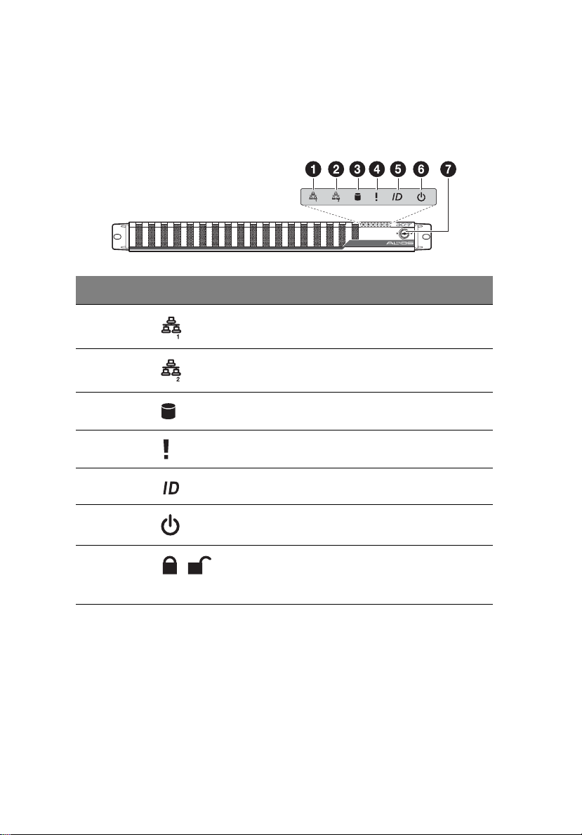
Front bezel
No. Icon Component
1 LAN1 activity indicator
2 LAN2 activity indicator
3 HDD activity indicator
4 Sysrem status indicator
1 System tour
5 System ID indicator
6 Power status indicator
7 Security keylock
This lock on the front bezel prevents
unauthorized access for maximum security.
Page 27
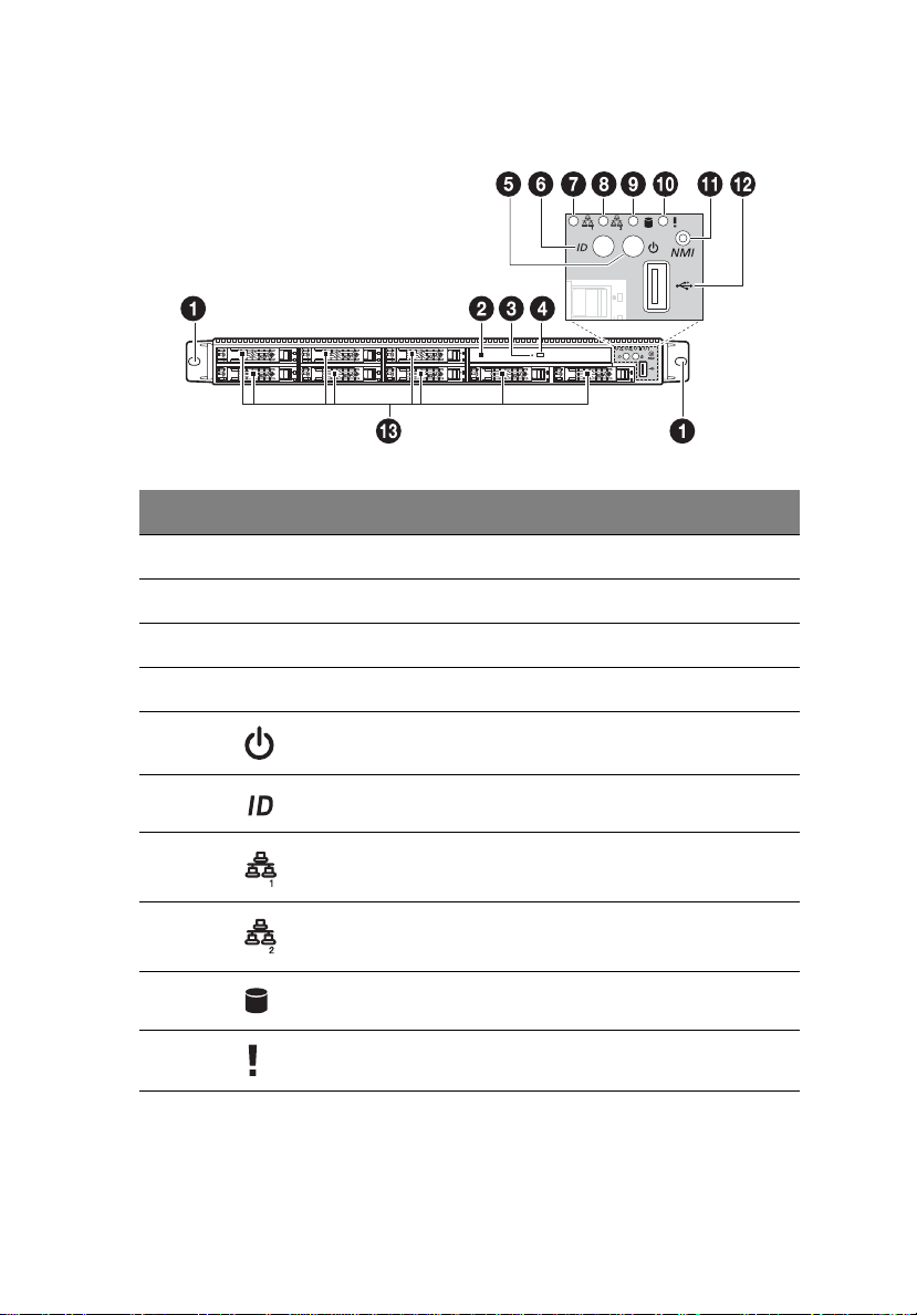
Front panel
No. Icon Component
1 Rack handles
2 Slim optical drive
3 Optical drive status indicator
4 Optical drive eject button
9
5 Power status indicator/ button
6 System ID indicator/button
7 LAN1 status indicator
8 LAN2 status indicator
9 Hard disk drive (HDD) activity indicator
10 System status indicator
Page 28

10
No. Icon Component
11 Non-maskable interrupt (NMI) button
Puts the server in a halt-state for diagnostic purposes
and allows the service technician to generate a NMI to
the processor to help debug server errors.
12 USB 2.0 port
13 2.5-inch hot-plug HDD bay
1 System tour
Page 29
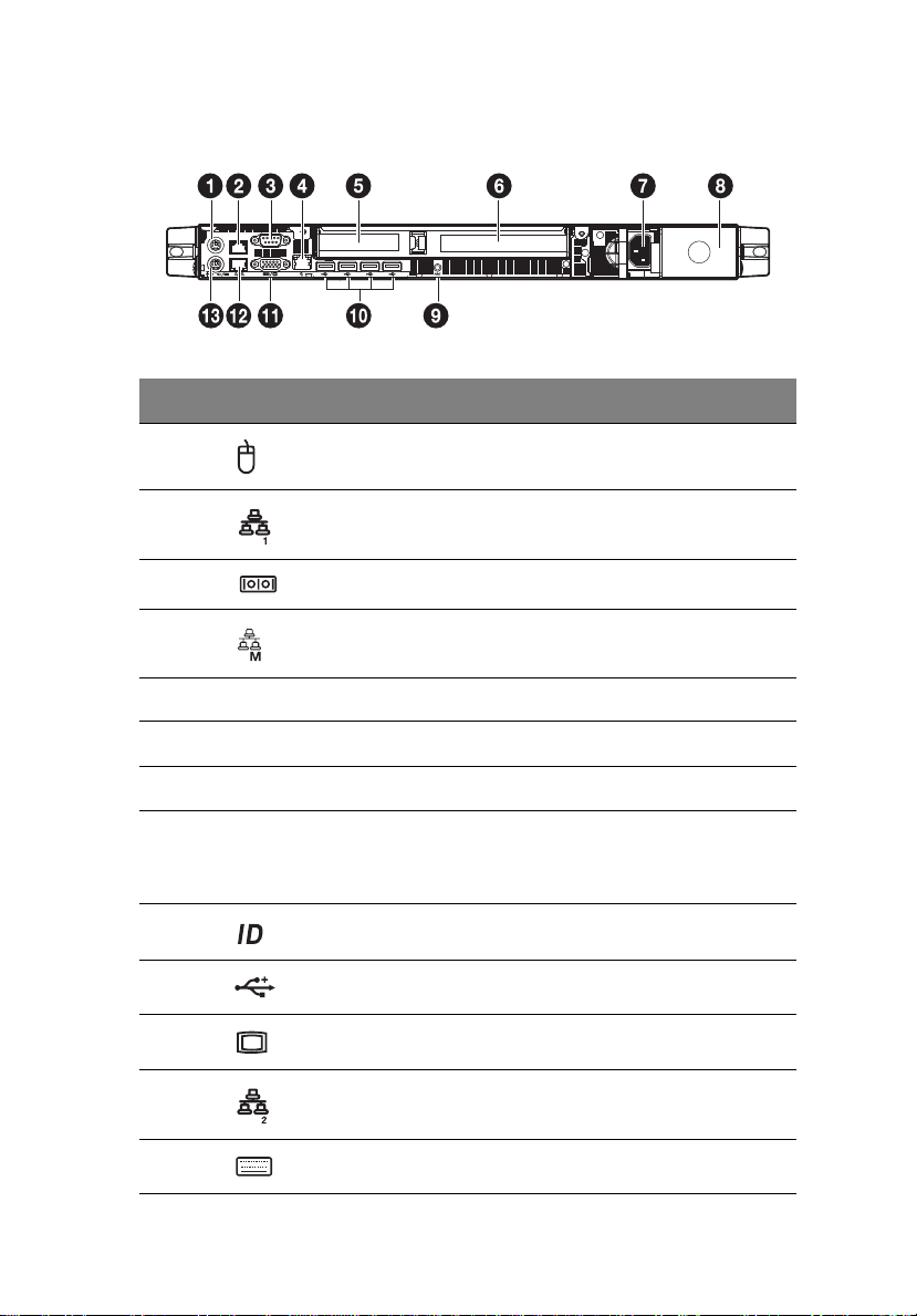
Rear panel
No. Icon Component
1 PS2 mouse port
11
2
3 Serial port (COM A)
4 Server management port (RJ-45) (10/100 Mbps)
5 Low profile PCI expansion slot
6 Full height PCI expansion slot
7 Power supply module
8 Power supply module bay
9 System ID indicator/button
10 USB 2.0 ports
11 Monitor port
12 LAN2 port (10/100/1000 Mbps)
LAN1 port (10/100/1000 Mbps)
Accommodates an optional hot-swap redundant
power supply module.
13 PS2 keyboard port
Page 30
12
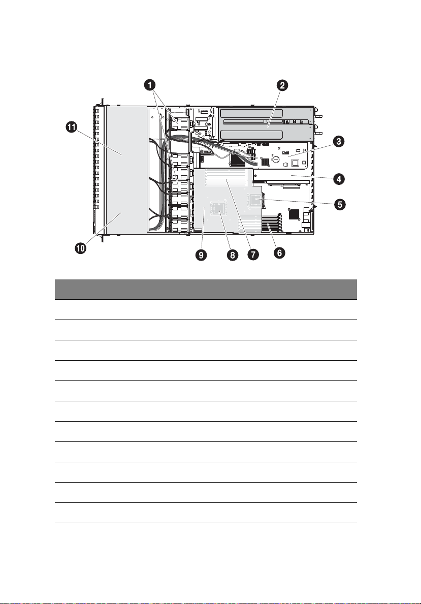
Internal components
No. Component
1 Dual-rotor fan module
1 System tour
2 Power supply module
3 Mainboard
4 PCI riser board bracket assembly
5Processor 1
6 Memory slots for Processor 1
7 Memory slots for Processor 2
8Processor 2
9 Air duct
10 Optical drive
11 Hard disk drives
Page 31

13
System boards
Mainboard
The mainboard becomes accessible once you open the system. It should
look like the figure shown below.
Page 32

14
No. Code Description
1 KB_MS1 Keyboard port
2 KB_MS2 Mouse port
3 GLAN1 Gigabit LAN port
4 GLAN2 Gigabit LAN port
5 COMA Serial port
6 VGA1 VGA port
7 RLAN_L1 Server management port (RJ-45)
8 R_USB1 - 4 USB 2.0 ports
9 SW1 ID switch
10 TPM_20 TPM connector
11 COMB Serial port connector
1 System tour
12 CPU2 Processor 2 socket
13 DIMMD1-D2
DIMME1-E2
DIMMF1-F2
14 CPU1 Processor 1 socket
15 SSI_2X4P2 8-pin power connector
16 DIMMA1-A2
DIMMB1-B2
DIMMC1-C2
17 F_USB1 USB cable connector (for tape drive)
18 F_PANEL1 Front panel connector
19 J2 SMBUS connector to backplane
DDR3 sockets for processor 2
DDR3 sockets for processor 1
Page 33

No. Code Description
20 U82 Intel 5520 chipset
21 ATX_12V1 24-pin power connector
22 SATA5 SATA 5 connector
23 SATA4 SATA 4 connector
24 SATA1 SATA 1 connector
25 SATA0 SATA 0 connector
26 SSI_2X4P1 8-pin power connector
15
27 SGPIO_JP1 SGPIO connector for backplane SAS/SATA
28 SGPIO_JP2 SGPIO connector for backplane SAS/SATA
29 USB_A1 USB type A connector
30 SATA3 SATA 3 connector
31 SATA2 SATA 2 connector
32 PSMI1 PSMI (power supply management interface)
33 U60 Intel ICH10R
34 F_USB2 Front USB cable connector
35 CLR_RTC Clear RTC jumper
36 CLR_CMOS Clear CMOS jumper
37 BAT CMOS battery
connector 1
connector 2
connector
Close 1-2: Normal operation (default)
Close 2-3: Clear RTC status
Close 1-2: Normal operation (default)
Close 2-3: Clear CMOS
Page 34

16
No. Code Description
38 BMC_SEL BMC selection jumper
Close 1-2: Normal operation (default)
39 BIOS_RVCR BIOS recovery jumper
Close 1-2: Normal operation (default)
Close 2-3: Enable BIOS recovery
40 SSD_USB1 USB SSD (solid state disk) type connector
41 U8 BIOS flash ROM
42 U5 BMC chipset
43 IPMB2 IPMB2 connector
44 IPMB1 IPMB1 connector
45 PASS_DIS Skip supervisor password jumper
Close 1-2: Normal operation (default)
Close 2-3: Clear Supervisor Password in BIOS setup
menu
46 U190 Winbond W83792G chipset
1 System tour
47 PCI-EX8_RU/
PCI-EX8_RD
48 J1 AMI Pilot II firmware upgrade connector
49 JP_STRP8 BMC firmware upgrade jumper
50 JP_STRP2 BMC firmware upgrade jumper
51 PILOT_DIS BMC force mode jumper
52 PCI-EX8_RR Low profile PCI-E riser slot
53 U27 ITE IT8720F chipset
Full height PCI-E riser slot
Close 2-3: Default setting
Close 2-3: Default setting
Close 1-2: Normal operation (default)
Close 2-3: Disable BMC device function
Page 35

No. Code Description
54 U23 Broadcom BCM5221PHY chipset
55 U6 Intel 82576EB GbE chipset
17
Page 36

18
1 System tour
Backplane board
The backplane board installed on the rear side of the hot-plug drive
bay provides support for both SAS and SATA hard drives.
No. Code Description
1 J1 SMBUS connector from RAID card
2 J2 SMBUS connector to mainboard
3 SAS/CON2 SAS data cable connector 2
4 J12 Debug port
5 SAS/CON1 SAS data cable connector 1
6 SGPIO_JP2 SGPIO jumper block
7 P2 Power cable connector
8 FAN_1A Fan 1A cable connector
9 FAN_1B Fan 1B cable connector
10 SGPIO_J1 SGPIO jumper block
11 FAN_2A Fan 2A cable connector
12 FAN_2B Fan 2B cable connector
13 FAN_3A Fan 3A cable connector
14 FAN_3B Fan 3B cable connector
15 FAN_4A Fan 4A cable connector
Page 37

No. Code Description
16 FAN_4B Fan 4B cable connector
17 FAN_5B Fan 5B cable connector
18 FAN_5A Fan 5A cable connector
19 FAN_6A Fan 6A cable connector
20 FAN_6B Fan 6B cable connector
21 J21 LED power select jumper
Close 1-2: No change
22 J27 HDD tray LED conduct jumper setting
Close 1-2: Two LEDs display (default)
19
Page 38

20
1 System tour
Riser board
The two riser boards installed on the PCI riser board bracket assembly
provides support for both full height and low profile expansion cards.
Full height riser board
No. Code Description
1 PCI_1 PCI Express 2.0 x16 slot (PCI Express 2.0 x16
throughput)
Low profile riser board
No. Code Description
1 PCI_2 PCI Express 2.0 x8 slot (PCI Express 2.0 x8
throughput)
Page 39

System LED indicators
This section describes the different LED indicators located on
• Front panel
• Hot-plug HDD carrier
• LAN port
Knowing what each LED indicator signifies can aid in problem
diagnosis and troubleshooting.
Front panel LED indicators
21
The following table list and describe the LED indicators available on
the front panel.
No. Indicator Color State Description
1 System ID Blue On System identification is active
Off System identification is disabled
Page 40

22
No. Indicator Color State Description
1 System tour
2Power
status
3LAN1
activity
4LAN2
activity
5 HDD activity Green Blink HDD access
6 System
status
Green On System has power applied to it or
ACPI S0 state
Blink System is in ACPI S1 state (sleep
mode)
N/A Off System is not powered on or in ACPI
S5 state (power off).
System is in ACPI S4 state (hibernate
mode).
Green On Link between system and network or
no access
Blink Network access
Green On Link between system and network or
no access
Blink Network access
N/A Off No access
Green On Running or normal operation
Blink System degraded due to CPU or
DIMM error
Amber On Critical or non-recoverable condition
(Power modules or voltage power
supply failure or critical
temperature)
Blink Non-critical condition
N/A Off System not ready
May indicate the following:
• POST error
•NMI event
• Processor or terminator missing
Page 41

Hot-plug HDD carrier LED indicators
1 2
Description
Green Red
HDD present On Off
HDD access Blink (4 Hz) Off
HDD failure Off On
HDD removed Off On
HDD connected and rebuilding data On Blink (1 Hz)
HDD locate Blink (4 Hz) Blink (4 Hz)
23
Page 42

24
LAN port LED indicators
No. Indicator Color State Description
1 System tour
1 Link/
activity
indicator
2 Speed
indicator
Green On Network link is detected
Blink Transmit or receive activity
N/A Off 10 Mbps connection
Green On 100 Mbps connection
Yellow On 1000 Mbps connection
Note: The server management
port does not support 1000
Mbps connection.
Page 43

2 System setup
Page 44

This chapter gives you instructions on how to set up
the system. Procedures on how to connect
peripherals are also explained.
Page 45

Setting up the system
Pre-installation requirements
Selecting a site
Before unpacking and installing the system, select a suitable site for
the system for maximum efficiency. Consider the following factors
when choosing a site for the system:
• Near a grounded power outlet
• Clean and dust-free
• Stable surface free from vibration
• Well-ventilated and away from sources of heat
• Secluded from electromagnetic fields produced by electrical
devices such as air conditioners, radio and TV transmitters, etc.
Checking the package contents
Check the following items from the package:
• Acer Altos R520 M2 system
• Acer Altos R520 M2 accessory box
27
If any of the above items are damaged or missing, contact your dealer
immediately.
Save the boxes and packing materials for future use.
Page 46

28
2 System setup
Connecting peripherals
Caution! The server operates on 100-127/200-240 VAC only. Do
not connect the system to an incorrect voltage source.
Refer to the illustration below for specific connection instructions on
the peripherals you want to connect to the system.
Note: Consult the operating system manual for information on
how to configure the network setup.
Page 47

Turning on the system
After making sure that you have properly set up the system and
connected all the required cables, you can now power on the system.
To power on the system:
1 Remove the front bezel. See “To remove the front bezel”section
on page 37.
2 After plugging the power cord, wait 40 seconds to fully initialize
the BMC, then press the power button.
29
The system starts up and displays a welcome message on the monitor.
After that, a series of POST messages appears. The POST messages
indicate if the system is running well or not.
Note: If the system does not turn on or boot after pressing the
power button, go to the next section for the possible causes of the
boot failure.
Aside from the POST messages, you can determine if the system is in
good condition by checking if the following occurred.
• The power indicator on the front panel lights up green
• The Num Lock, Caps Lock, and Scroll Lock indicators on the
keyboard light up
Page 48

30
2 System setup
Power-on problems
If the system does not boot after you have applied power, check the
following factors that might have caused the boot failure.
• The external power cord may be loosely connected.
Check the power cord connection from the power source to the
power supply module AC input connector on the rear panel. Make
sure that the power cord is properly connected to the power
source and to the AC input connector.
• No power comes from the grounded power outlet.
Have an electrician check your power outlet.
• Loose or improperly connected internal power cables.
Check the internal cable connections. If you are not confident to
perform this step, ask a qualified technician to assist you.
Warning! Make sure all power cords are disconnected from
the electrical outlet before performing this task.
Note: If you have gone through the preceding actions and the
system still fails to boot, ask your dealer or a qualified technician
for assistance.
Page 49

Configuring the system OS
31
The Acer Altos R520 M2 comes with Acer EasyBUILD
TM
that allows you
to conveniently install your choice of operating system.
Note: To purchase the Acer EasyBUILD software, contact your
local Acer representative.
To start using EasyBUILD, follow the steps below.
1 Locate the EasyBUILD DVD included in the system package.
2 With the system turned on, gently press the optical drive’s Stop/
Eject button.
3 When the disc tray slides open, insert the EasyBUILD DVD with the
label or title side of the disc facing upward.
Note: When handling the disc, hold it by the edges to avoid
smudges or fingerprints.
4 Gently press the disc down to make sure that it is properly
inserted.
Caution! While pressing the disc, be careful not to bend the disc
tray. Make sure that the disc is properly inserted before closing
the disc tray. Improper insertion may damage both the disc and
the CD-ROM drive.
5 Gently press the drive Stop/Eject button again to close the disc
tray.
6 On the Acer EasyBUILD System Setup window, select OS
Installation.
7 Follow all onscreen instructions.
For more information, refer to the EasyBUILD Help file.
Note: Windows or Linux OS CD is needed when you install the OS
with the EasyBUILD DVD.
Page 50

32
2 System setup
Turning off the system
There are two ways to turn off the server—via software or via
hardware. The software procedure below applies to a system running
on Windows operating system. For further operating system shutdown
procedures, refer to the related user documentation.
To turn off the system via software:
1 Press the Ctrl+Alt+Delete on the attached keyboard or click the
Start on the Windows taskbar.
2 Select Shut Down.
3 Select Shut down from the drop-down window then click on OK.
To turn off the system via hardware:
If you cannot shut down the server using the software, press the power
button for at least four seconds. Quickly pressing the button may put
the server in a Suspend mode only.
Page 51

3 System upgrade
Page 52

This chapter discusses the precautionary measures
and installation procedures you need to know to
upgrade the system.
Page 53

Installation precautions
Before you install any server component, we recommend that you read
the following sections. These sections contain important ESD
precautions along with pre-installation and post-installation
instructions.
ESD precautions
Electrostatic discharge (ESD) can damage the processor, disk drives,
expansion boards, motherboard, memory modules and other server
components. Always observe the following precautions before you
install a server component:
• Do not remove a component from its protective packaging until
you are ready to install it.
• Do not touch the component pins, leads, or circuitry.
• Components with a Printed Circuit Board (PCB) assembly should
always be laid with the assembly-side down.
• Wear a wrist grounding strap and attach it to a metal part of the
server before handling components. If a wrist strap is not
available, maintain contact with the server throughout any
procedure requiring ESD protection.
• Keep the work area free of nonconductive materials, such as
ordinary plastic assembly aids and foam packing.
35
Page 54

36
3 System upgrade
Pre-installation instructions
Perform the steps below before you open the server or before your
remove or replace any component:
Warning! Failure to properly turn off the server before you
start installing components may cause serious damage. Do
not attempt the procedures described in the following
sections unless you are a qualified service technician.
1 Turn off the system and all the peripherals connected to it.
2 Unplug all cables from the power outlets.
3 Disconnect all telecommunication cables from their ports.
4 Place the system unit on a flat, stable surface.
5 Open the system according to the instructions on page 37.
6 Follow the ESD precautions described in this section when
handling a server component.
Post-installation instructions
Perform the steps below after installing a server component.
1 See to it that all components are installed according to the
described step-by-step instructions.
2 Reinstall all components or cable that have been previously
removed.
3 Reinstall the top cover.
4 Reinstall the front bezel.
5 Reconnect the necessary cables.
6 Turn on the system.
Page 55

Opening the server
Caution! Before you proceed, make sure that you have turned
off the system and all peripherals connected to it. Read the “Preinstallation instructions” on page 36.
You need to open the server before you can install additional
components. The front bezel and top cover are removable to allow
access to the system’s internal components. Refer to the following
sections for instructions.
Removing and installing the front bezel
To remove the front bezel:
1 If necessary, unlock the front bezel.
(1) Insert the key into the lock.
(2) Turn the key counterclockwise to the unlocked position. Make
sure the small colored dot is aligned with the unlock icon.
37
Page 56

38
2 Grasp the front bezel at the outer edge and pull it straight out.
3 System upgrade
To install the front bezel:
1 Align the notch on left side of the bezel to the guides on the rack
handle.
2 Snap the bezel to the right side of the chassis.
Page 57

Removing and installing the top cover
To remove the top cover:
1 Observe the ESD precautions and pre-installation instructions
described on page 35.
2 Remove the top cover.
(1) Remove the two screws located on the top cover.
(2) Press and hold the release button.
(3) Slide the cover toward the back of the chassis until the cover
disengage with the slots on the chassis.
(4) Lift the top cover away from the server.
39
3 Put the top cover aside for reinstallation later.
Page 58

40
3 System upgrade
To install the top cover:
1 Perform the pre-installation instructions described on page 35.
2 Install the top cover.
(1) Place the top cover on the chassis so that the tabs on the cover
align with the slots on the chassis.
(2) Slide the top cover toward the front of the chassis until it is
fully closed.
(3) Replace the two screws on the top cover.
Page 59

Removing and installing the air duct
Caution! Always operate your server with the air duct installed to
ensure reliable and continued operation.
You need to remove the air duct to perform the following procedures:
• Removing and installing a processor
• Removing and installing a memory module
To remove the air duct:
1 Perform the pre-installation instructions described on page 35.
2 Lift the air duct from the chassis.
41
Page 60

42
3 System upgrade
To install the air duct:
1 Perform the pre-installation instructions described on page 35.
2 Place the air duct on the chassis so that the tabs on the air duct
align with the slots on the chassis.
Caution! Do not pinch or unplug cables that may be near or
under the air duct.
3 Observe the post-installation instructions described on page 36.
Page 61

43
Configuring the storage devices
The system accommodates slim-line optical drives and can support up
to eight 2.5-inch hot-plug SAS/SATA hard disk drives.
Caution! To ensure proper airflow and server cooling, all drive
bays must contain either a carrier with a hard drive installed in it
or a hard disk carrier cover.
Removing and installing a hard disk drive
Hard disk drive configuration guidelines
Observe these guidelines when replacing or installing a hard disk drive.
• Use only Acer-qualified SAS or SATA HDDs. To purchase a SAS or
SATA HDD, contact your local Acer representative.
• Before removing a hard disk drive, make sure to back up all
important system files.
• Check hard disk drive status by checking the status LED indicators
on the HDD carrier.
• The hard disk drives must be installed in the following order.
Determining drive status
Each HDD carrier features two status LED indicators to display the hard
drive status. If you are replacing a failed HDD, determine which drive
has failed by checking the drive status LED. For more information on
how to determine the drive status, refer to “Hot-plug HDD carrier LED
indicators” on page 23.
Page 62

44
3 System upgrade
To remove an HDD:
1 Observe the ESD precautions described on page 35.
2 Remove the front bezel. Perform the instructions described in “To
remove the front bezel” section on page 37.
3 If you are removing a failed HDD, determine which drive has failed
by checking the drive status LEDs.
4 Remove the HDD carrier.
(1) Unlock the HDD carrier latch.
(2) Press the HDD carrier latch.
(3) Pull the lever and slide the carrier from the chassis.
5 Observe the post-installation instructions described on page 36.
For instructions on how to install a new hard disk, refer to the next
section.
To install an HDD:
Note: To purchase an HDD carrier, contact your local Acer
representative.
1 Perform steps 1 to 4 described in the “To remove a HDD” section
on page 44.
Page 63

2 If necessary, remove the air baffle from the HDD carrier.
(1) Remove the four screws that secure the air baffle to the HDD
carrier.
(2) Remove the air baffle from the HDD carrier.
(3) Save the air baffle and screws for later use.
3 Remove the new HDD from its protective packaging.
4 Install the new HDD to the HDD carrier.
(1) Place the HDD into the HDD carrier.
(2) Secure it with the four screws that came with the HDD carrier.
45
Page 64

46
3 System upgrade
5 Install the HDD carrier into the drive bay.
(1) With the lever still extended, slide the HDD carrier all the way
into the drive bay.
(2) Use the lever to push the HDD carrier until it locks into place,
then close the HDD carrier lever.
(3) Lock the HDD carrier.
6 Observe the post-installation instructions described on page 36.
Page 65

47
Installing and removing an optical drive
Note: The optical drive is not hot-pluggable. Before removing or
replacing the drive, you must first power down the server, unplug
the AC power cord from the system, and turn off all peripherals
devices connected to the server.
To install an optical drive:
1 Perform the pre-installation instructions described on page 35.
2 Remove the front bezel. Perform the instructions described in “To
remove the front bezel” section on page 37.
3 If a filler panel is installed, remove it from the drive bay.
4 Remove the access panel and optical drive tray.
(1) Remove the four screws that secure the access panel to the
chassis.
(2) Slide the access panel to disengage from the chassis, then lift
the access panel off the chassis. Put the access panel aside for
reinstallation later.
(3) Remove the two screws that secure the optical drive tray to
the chassis.
Page 66

48
3 System upgrade
(4) Slide the drive tray out through the front of the server.
5 Remove the new drive from its protective packaging.
6 Install the optical drive.
(1) Slide the optical drive into the drive tray.
(2) Secure it with the four screws that came with the optical drive
kit.
Page 67

7 Install the optical drive tray.
(1) Slide the optical drive tray into the front opening in the server.
(2) Secure the optical drive tray to the chassis with two screws.
(3) Connect the SATA ODD cable to the optical drive.
8 Install the access panel.
(1) Place the access panel on the chassis so that the tabs on the
panel align with the slots on the chassis, then slide the panel
toward the front of the chassis until it is fully closed.
(2) Replace the four screws on the access panel.
49
9 Observe the post-installation instructions described on page 36.
Page 68

50
3 System upgrade
To remove an optical drive:
1 Perform the pre-installation instructions described on page 35.
2 Remove the front bezel. Perform the instructions described in “To
remove the front bezel” section on page 37.
3 Remove the access panel.
(1) Remove the four screws that secure the access panel to the
chassis.
(2) Slide the access panel to disengage from the chassis, then lift
the access panel off the chassis.
(3) Put the access panel aside for reinstallation later.
Page 69

4 Remove the optical drive tray.
(1) Disconnect the SATA ODD cable attached to the optical drive.
(2) Remove the two screws that secure the drive tray to the
chassis.
(3) Slide the drive tray out through the front of the server.
5 Remove the optical drive.
(1) Remove the four screws that secure the optical drive to the
drive tray.
(2) Slide the optical drive out of the drive tray.
51
6 Observe the post-installation instructions described on page 36.
If installing a new optical drive, see “To install an optical drive”
section on page 47 section.
Page 70

52
3 System upgrade
Replacing a dual-rotor fan module
Altos R520 M2 includes seven dual-rotor fan modules to provide
adequate airflow and keep system running cool.
Fan cable connectors
Refer to the following illustration for location of the dual-rotor fan
modules and fan cable connectors.
To replace a dual-rotor fan module:
1 Perform the pre-installation instructions described on page 36.
Warning! The system fan becomes very hot when the
system is on. Allow it to cool off first before handling.
2 Identify the defective fan.
Page 71

3 Remove the fan module.
(1) Disconnect the two fan cables.
(2) Press the release tabs on the fan module and pull it up and
away from the chassis.
53
Page 72

54
3 System upgrade
4 Install the new dual-rotor fan module.
(1) Slide the new fan into the chassis.
(2) Connect the two fan cables. Check the routing of all cables for
obstructions.
5 Observe the post-installation instructions described on page 36.
Page 73

55
Upgrading the processor
Processor configuration guidelines
Altos R520 M2 supports two LGA 1366 processor sockets supporting
dual-core or quad-core Intel Xeon processors. You have the option to
upgrade the default processor or install a second one for a dualprocessor configuration.
Observe the following guidelines when replacing or installing a
processor.
• The processor 1 socket must always be populated. If no processor is
installed in this socket, the system will fail to boot.
• Before removing a processor, make sure to back up all important
system files.
• When installing a second processor, make sure it has same
stepping and frequency specifications as the default processor.
• Handle the processor and the heat sink carefully. Damage to either
may prevent the system from functioning properly.
To upgrade the default processor:
1 Perform the pre-installation instructions described on page 35.
Warning! The heat sink becomes very hot when the system
is on. NEVER touch the assembly with any metal or with
your hands.
2 Remove the air duct. Perform the instructions described in “To
remove the air duct” section on page 41.
3 Remove the heat sink.
(1) Loosen the four captive screws on the heat sink.
Page 74

56
3 System upgrade
(2) Pull the heat sink away from the processor.
(3) Lay down the heat sink in an upright position — with the
thermal patch facing upward. Do not let the thermal patch
touch the work surface.
(4) Use an alcohol prep pad to wipe off the thermal grease from
both the heat sink and the processor socket retention plate.
4 Remove the default processor.
Warning! The processor becomes very hot when the system
is on. Allow it to cool off first before handling.
(1) Release then lift the load lever.
(2) Open the retention plate to expose the socket body.
Page 75

(3) Grasp the processor by its edges and lift it out of its socket.
(4) Store the old processor inside an anti-static bag.
5 Remove the new processor from its protective packaging.
6 Install the new processor.
(1) Hold the processor by its edges. Make sure the alignment tabs
on the socket fit the two notch located on the edge of the
processor. The pins are keyed in such a way that you cannot
install the processor in the wrong orientation without
bending the pins.
(2) Insert the new processor in the socket.
(3) Close the retention plate.
(4) Engage the load lever back into place.
57
Page 76

58
3 System upgrade
7 Apply the thermal interface material.
(1) Use an alcohol pad to wipe off the old thermal grease from
both the heat sink and the processor socket retention plate.
(2) Apply a thin layer of an Acer-approved thermal interface
material before installing the heat sink.
Make sure that only a very thin layer is applied so that both
contact surfaces are still visible.
8 Install the heatsink.
Caution! The heat sink has a thermal interface material (TIM) on
the underside. Use caution so that you do not damage the TIM. If
a protective film is installed on the TIM, remove it.
(1) Set the heat sink over the processor, aligning the four captive
screws with the four screw posts surrounding the processor.
(2) Loosely screw in the captive screws on the heat sink corners in
a diagonal manner.
Note: Do not fully tighten one screw before tightening another.
(3) Gradually and equally tighten each captive screw until each is
firmly tightened.
9 Observe the post-installation instructions described on page 36.
Page 77

To install a second processor :
1 Perform steps 1 to 3 of the previous section.
2 Prepare the processor 2 socket for installation.
(1) Refer to steps 4-1 and 4-2 of the previous section.
(2) Remove the socket cap from the processor socket.
59
3 Install the new processor.
Refer to steps 6 and 7 of the previous section.
4 Install the heat sink.
Refer to step 8 of the previous section.
5 Observe the post-installation instructions described on page 36.
Page 78

60
3 System upgrade
Upgrading the system memory
System memory interface
Acer Altos R520 M2 has twelve DIMM slots. The DIMM slots are colorcoded and are labeled DIMM A1, DIMM A2, DIMM B1, DIMM B2, DIMM
C1, DIMM C2, DIMM D1, DIMM D2, DIMM E1, DIMM E2, DIMM F1, and
DIMM F2.
All twelve DIMM slots are shared by two processors. Each processor
controls six DIMM slots. The DIMM slots support three channel DDR3133 registered/unbuffered ECC memory modules. For processor 1, it
will be channels A, B, and C and for processor 2, it will be channels D, E,
and F. Each channel is divided into two sockets: Socket 1 and Socket 2.
Socket 1 slots are colored blue and comprised of DIMM slots A1, B1, C1,
D1, E1, and F1 and Socket 2 slots are colored black and comprised of
DIMM slots A2, B2, C2, D2, E2, and F2.
For all memory channel modes, populate the blue slots first, before
populating the black slots. If DIMM slots in Socket 1 are empty, the
DIMM slots in Socket 2 can not be used.
Page 79

61
System memory configuration guidelines
• To ensure data integrity, use only Acer-approved 240-pin, DDR3
1333 MHz ECC unbuffered DIMM (UDIMM) or registered DIMM
(RDIMM) modules.
• If you are using a single-processor configuration, you should install
the memory module into DIMM A1 to DIMM C2 slots.
The DIMM D1 to DIMM F2 slots are enabled when a second
processor is installed on the mainboard.
• DIMM modules of the same type, size, and manufacturer must be
installed in the same colored DIMM slots.
• Follow the population sequence illustrated in the next section
when installing a memory module.
Page 80

62
3 System upgrade
Memory module population sequence
The tables below list the suggested population sequence when
installing a memory module.
Independent mode
Single processor configuration
Total Capacity DIMM A2 DIMM A1 DIMM B2 DIMM B1 DIMM C2 DIMM C1
1GB 1GB
2GB 1GB 1GB
3GB 1GB 1GB 1GB
4GB 1GB 1GB 1GB 1GB
6GB 1GB 1GB 1GB 1GB 1GB 1GB
2GB 2GB
4GB 2GB 2GB
6GB 2GB 2GB 2GB
8GB 2GB 2GB 2GB 2GB
12GB 2GB 2GB 2GB 2GB 2GB 2GB
4GB 4GB
8GB 4GB 4GB
12GB 4GB 4GB 4GB
16GB 4GB 4GB 4GB 4GB
24GB 4GB 4GB 4GB 4GB 4GB 4GB
8GB* 8GB
16GB* 8GB 8GB
24GB* 8GB 8GB 8GB
32GB* 8GB 8GB 8GB 8GB
48GB* 8GB 8GB 8GB 8GB 8GB 8GB
* support depends on 8GB DIMM availability.
Page 81

Dual-processor configuration
To ta l
Capacity
2GB 1GB 1GB
3GB 1GB 1GB 1GB
4GB 1GB 1GB 1GB 1GB
6GB 1GB 1GB 1GB 1GB 1GB 1GB
8GB 1GB 1GB 1GB 1GB 1GB 1GB 1GB 1GB
9GB 1GB 1GB 1GB 1GB 1GB 1GB 1GB 1GB 1GB
12GB 1GB 1GB 1GB 1GB 1GB 1GB 1GB 1GB 1GB 1GB 1GB 1GB
4GB 2GB 2GB
6GB 2GB 2GB 2GB
8GB 2GB 2GB 2GB 2GB
12GB 2GB 2GB 2GB 2GB 2GB 2GB
16GB 2GB 2GB 2GB 2GB 2GB 2GB 2GB 2GB
18GB 2GB 2GB 2GB 2GB 2GB 2GB 2GB 2GB 2GB
24GB 2GB 2GB 2GB 2GB 2GB 2GB 2GB 2GB 2GB 2GB 2GB 2GB
4GB 4GB 4GB
12GB 4GB 4GB 4GB
16GB 4GB 4GB 4GB 4GB
24GB 4GB 4GB 4GB 4GB 4GB 4GB
32GB 4GB 4GB 4GB 4GB 4GB 4GB 4GB 4GB
36GB 4GB 4GB 4GB 4GB 4GB 4GB 4GB 4GB 4GB
48GB 4GB 4GB 4GB 4GB 4GB 4GB 4GB 4GB 4GB 4GB 4GB 4GB
16GB* 8GB 8GB
24GB* 8GB 8GB 8GB
32GB* 8GB 8GB 8GB 8GB
48GB* 8GB 8GB 8GB 8GB 8GB 8GB
64GB* 8GB 8GB 8GB 8GB 8GB 8GB 8GB 8GB
72GB* 8GB 8GB 8GB 8GB 8GB 8GB 8GB 8GB 8GB
96GB* 8GB 8GB 8GB 8GB 8GB 8GB 8GB 8GB 8GB 8GB 8GB 8GB
* support depends on 8GB DIMM availability.
DIMM
A2 A1 B2 B1 C2 C1 D2 D1 E2 E1 F2 F1
63
Page 82

64
3 System upgrade
Mirrored or lockstep memory configuration
Memory configuration guidelines
• DIMM modules installed in channels A and B must be identical—
A1 and B1 should be the same type, size and manufacturer.
A2 and B2 memory should be the same type, size and
manufacturer.
• Channel C has no function in mirrored or lockstep memory
configuration. Same rule applies for channels D, E, and F of
processor 2 socket.
• The effective memory size is reduced by at least one-half in
mirrored memory configuration.
Mirrored memory configuration
Single processor configuration
Processor 1
DIMM A1DIMM A2DIMM B1DIMM B2DIMM C1DIMM C2DIMM D1DIMM D2DIMM BEDIMM E2DIMM F1DIMM F2Physical
1GB 1GB
1GB 1GB 1GB
2GB 2GB
2GB 2GB 2GB
4GB 4GB
4GB 4GB 4GB
8GB 8GB
8GB 8GB 8GB
(M)
(M)
(M)
(M)
(M)
(M)
(M)
(M)
1GB
(M)
2GB
(M)
4GB
(M)
8GB
(M)
Processor 2
Total Me m o r y
Memory
2GB 1GB
4GB 2GB
4GB 2GB
8GB 4GB
8GB 4GB
16GB 8GB
16GB 8GB
32GB 16GB
* (M) stands for Mirror
Detecte
d by OS
Page 83

Dual processor configuration
65
Processor 1
DIMM A1DIMM A2DIMM B1DIMM B2DIMM C1DIMM C2DIMM D1DIMM D2DIMM BEDIMM E2DIMM F1DIMM F2Physical
1GB 1GB
1GB 1GB 1GB
1GB 1GB 1GB
2GB 2GB
2GB 2GB 2GB
2GB 2GB 2GB
4GB 4GB
4GB 4GB 4GB
4GB 4GB 4GB
8GB 8GB
8GB 8GB 8GB
8GB 8GB 8GB
(M)
(M)
(M)
(M)
(M)
(M)
(M)
(M)
(M)
(M)
(M)
(M)
1GB
(M)
1GB
(M)
2GB
(M)
2GB
(M)
4GB
(M)
4GB
(M)
8GB
(M)
8GB
(M)
Processor 2
1GB 1GB
1GB 1GB
1GB 1GB 1GB
2GB 2GB
2GB 2GB 2GB
2GB 2GB 2GB
4GB 4GB
4GB 4GB 4GB
4GB 4GB 4GB
8GB 8GB
8GB 8GB 8GB
8GB 8GB 8GB
(M)
(M)
(M)
(M)
(M)
(M)
(M)
(M)
(M)
(M)
(M)
(M)
1GB
(M)
2GB
(M)
4GB
(M)
8GB
(M)
Total Me m o r y
Memory
4GB 2GB
6GB 3GB
8GB 4GB
8GB 4GB
12GB 6GB
16GB 8GB
16GB 8GB
24GB 12GB
32GB 16GB
32GB 16GB
48GB 24GB
64GB 32GB
* (M) stands for Mirror
Detecte
d by OS
Page 84

66
Lockstep memory configuration
Single processor configuration
3 System upgrade
Processor 1
DIMM A1DIMM A2DIMM B1DIMM B2DIMM C1DIMM C2DIMM D1DIMM D2DIMM BEDIMM E2DIMM F1DIMM F2Physical
1GB 1GB 2GB 2GB
1GB 1GB 1GB 1GB 4GB 4GB
2GB 2GB 4GB 4GB
2GB 2GB 2GB 2GB 8GB 8GB
4GB 4GB 8GB 8GB
4GB 4GB 4GB 4GB 16GB 16GB
8GB 8GB 16GB 16GB
8GB 8GB 8GB 8GB 32GB 32GB
Processor 2
Total Me m o r y
Detecte
Memory
d by OS
Dual processor configuration
Processor 1
DIMM A1DIMM A2DIMM B1DIMM B2DIMM C1DIMM C2DIMM D1DIMM D2DIMM BEDIMM E2DIMM F1DIMM F2Physical
1GB 1GB 1GB 1GB 4GB 4GB
1GB 1GB 1GB 1GB 1GB 1GB 6GB 6GB
1GB 1GB 1GB 1GB 1GB 1GB 1GB 1GB 8GB 8GB
2GB 2GB 2GB 2GB 8GB 8GB
2GB 2GB 2GB 2GB 2GB 2GB 12GB 12GB
2GB 2GB 2GB 2GB 2GB 2GB 2GB 2GB 16GB 16GB
4GB 4GB 4GB 4GB 16GB 16GB
4GB 4GB 4GB 4GB 4GB 4GB 24GB 24GB
4GB 4GB 4GB 4GB 4GB 4GB 4GB 4GB 32GB 32GB
8GB 8GB 8GB 8GB 32GB 32GB
8GB 8GB 8GB 8GB 8GB 8GB 48GB 48GB
8GB 8GB 8GB 8GB 8GB 8GB 8GB 8GB 64GB 64GB
Processor 2
Total Me m o r y
Detecte
Memory
d by OS
To install a memory module:
Warning! Memory of the identical size, speed, and
organization must be installed in the same colored DIMM
slots.
Page 85

1 Perform the pre-installation instructions described on page 36.
2 Remove the air duct. Perform the instructions described in “To
remove the air duct” section on page 41.
3 Locate the DIMM slots on the mainboard.
4 Install the memory module.
(1) Align then insert the DIMMs into the sockets.
(2) Push the DIMM to the socket until the retaining clips snap
inward.
67
Note: The DIMM slot is slotted to ensure proper installation. If
you insert a DIMM but it does not fit easily into the socket, you
may have inserted it incorrectly. Reverse the orientation of the
DIMM and insert it again.
5 Observe the post-installation instructions described on page 36.
6 Reconfigure the system memory. See ‘To reconfigure the system
memory” section on page 69 for more information.
Page 86

68
3 System upgrade
To remove a memory module:
Important: Before removing any DIMM from the mainboard,
make sure to create a backup file of all important data.
1 Perform the pre-installation instructions described on page 36.
2 Remove the air duct to access the DIMM slots. Perform the
instructions described in “To remove the air duct” section on page
41.
3 Remove the memory module.
(1) Press the holding clips on both sides of the DIMM slot outward
to release the DIMM.
(2) Gently pull the DIMM upward to remove it from the DIMM
slot.
4 If you intend to install a new DIMM, refer to previous section for
related procedure, otherwise reinstall the air duct, then observe
the post-installation instructions described on page 36.
Page 87

69
To reconfigure the system memory:
The system automatically detects the amount of memory installed. Run
the BIOS setup to view the new value for total system memory and
make a note of it.
Page 88

70
3 System upgrade
Installing an expansion card
Altos R520 M2 has two PCI riser boards attached to a PCI riser board
bracket assembly that support full height and low profile expansion
cards.
• Full height riser slot
• One PCI Express 2.0 x16 slot (PCI Express 2.0 x16 throughput)
• Low profile riser slot
• One PCI Express 2.0 x8 slot (PCI Express 2.0 x8 throughput)
Caution! The PCI riser board bracket assembly must be installed
to maintain proper airflow inside the server.
To install an expansion card
1 Perform the pre-installation instructions described on page 35.
2 Remove the PCI riser board bracket assembly.
(1) Remove the three screws on the PCI riser board bracket
assembly.
(2) Gently pull the bracket assembly to disengage from the
chassis, then lift the bracket assembly from the chassis.
3 Remove the new expansion card from its packaging, handling it by
the edges.
Page 89

4 Remove the expansion slot cover.
(1) Remove the screw that secures the slot cover to the metal
bracket.
(2) Slide the cover out, then store it for reassembly later.
Caution: Do not discard the slot cover. If the expansion card is
removed in the future, the slot cover must be reinstalled to
maintain proper system cooling.
5 Install the expansion card.
(1) Align and insert the expansion card until it seats in the slot
bracket.
(2) Secure the card with the screw removed earlier.
71
Page 90

72
3 System upgrade
6 Install the PCI riser board bracket assembly.
(1) Position the bracket assembly over the PCI riser slot on the
mainboard, then push the bracket assembly down until it is
securely seated.
(2) Secure the bracket assembly to the chassis with the three
screws.
7 Connect the cables to the installed expansion card.
8 Observe the post-installation instructions described on page 36.
Page 91

73
Installing the TPM module
The optional TPM module allows system administrators to enhance the
security of the Altos R520 M2 system.
To install the TPM module:
1 Perform the pre-installation instructions described on page 35.
2 Locate the TPM module connector. If necessary, remove any boards
or cables that prevent access to it.
3 Remove the TPM module from its protective packaging, handling
it by the edges.
4 Install the TPM module.
Insert the TPM module into the TPM module connector.
5 Observe the post-installation instructions described on page 42.
6 Enable the TPM in BIOS. Refer to “Security menu” on page 107 for
more information.
Page 92

74
3 System upgrade
Installing and removing a power supply module
The server has two power supply module bays on the rear panel that
accept hot-plug power supply modules. The system ships out with only
a single power supply module installed. You have the option to
purchase an extra power supply module to provide the system with a
redundant power source. A redundant power configuration enables a
fully-configured system to continue running even if one power supply
module fails.
WARNING! To reduce the risk of personal injury or damage to
the equipment, the installation of power supply modules
should be referred to individuals who are qualified to service
server systems and are trained to deal with equipment capable
of generating hazardous energy levels.
WARNING! To reduce the risk of personal injury from hot
surfaces, observe the thermal labels on each power supply
module. You can also consider wearing protective gloves.
WARNING! To reduce the risk of personal injury from electric
shock hazards, do not open the power supply modules. There
are no serviceable parts inside the module.
Caution! Electrostatic discharge can damage electronic
components. Make sure that you are properly grounded before
handling a power supply module.
Caution! Due to chassis airflow disruption, a power supply bay
should never be vacant for more than two minutes when the
server is powered on. Exceeding five minutes might cause the
system to exceed the maximum acceptable temperature and
possibly damage the system components.
Caution! The power supply is only hot-pluggable if you have a
redundant system with two power supplies installed. If you
only have one power supply installed, before removing or
replacing the power supply, you must first take the server out
of service, turn off all peripheral devices connected to the
system, turn off the system by pressing the power button, and
unplug the AC power cord from the system or wall outlet.
Page 93

To install a second power supply module:
1 Observer the ESD precautions described on page 35.
2 If a filler panel is installed, remove the filler panel.
(1) Using your thumb and index finger, squeeze the filler panel
latch to release the filler panel from the chassis.
(2) Pull the filler panel out of the power supply module bay.
75
3 Insert the new power supply module into the empty module bay,
until it locks into place.
Page 94

76
3 System upgrade
To remove a power supply module:
Caution! Power supply hot-plug operations should be performed
only if a failure occurs in the power supply.
1 If there are more than one power supply modules installed,
determine which power supply module has failed.
2 Remove the AC power cord from the power supply being replaced.
3 Remove the power supply module.
(1) Press the power supply latch to release the power supply
module from the chassis.
(2) Use the handle to pull the power supply module out of the
server.
4 Install a new power supply module or install a filler panel to the
empty bay.
Page 95

4 System BIOS
Page 96

This chapter gives information about the
system BIOS and discusses how to configure
the system by changing the settings of the
BIOS parameters.
Page 97

79
BIOS overview
BIOS setup is a hardware configuration program built into the system's
Basic Input/Output System (BIOS). Since most systems are already
properly configured and optimized, there is no need to run this utility.
You will need to run this utility under the following conditions.
• When changing the system configuration settings
• When redefining the communication ports to prevent any conflicts
• When modifying the power management configuration
• When changing the password or making other changes to the
security setup
• When a configuration error is detected by the system and you are
prompted ("Run Setup" message) to make changes to the BIOS
setup
Note: If you repeatedly receive Run Setup messages, the battery
may be bad. In this case, the system cannot retain configuration
values in CMOS. Ask a qualified technician for assistance.
BIOS setup loads the configuration values in a battery-backed
nonvolatile memory called CMOS RAM. This memory area is not part of
the system RAM which allows configuration data to be retained when
power is turned off.
Before you run the PhoenixBIOS Setup Utility, make sure that you have
saved all open files. The system reboots immediately after you close the
Setup.
Note: PhoenixBIOS Setup Utility will be simply referred to as
"Setup" or "Setup utility" in this guide.
The screenshots used in this guide display default system values.
These values may not be the same those found in your system.
Page 98

80
4 System BIOS
Entering BIOS setup
1 Turn on the server and the monitor.
If the server is already turned on, close all open applications, then
restart the server.
2 During POST, press F2.
If you fail to press F2 before POST is completed, you will need to
restart the server.
The Setup Main menu will be displayed showing the Setup’s menu
bar. Use the left and right arrow keys to move between selections
on the menu bar.
BIOS setup primary menus
The tabs on the Setup menu bar correspond to the six primary BIOS
Setup menus, namely:
•Main
•Advanced
•Power
•Security
• Server
•Boot
• Exit
In the descriptive table following each of the menu screenshots,
settings in boldface are the default and suggested settings.
Page 99

81
BIOS setup navigation keys
Use the following keys to move around the Setup utility.
• Left and Right arrow keys – Move between selections on the
menu bar.
• Up and Down arrow keys – Move the cursor to the field you want.
• PgUp and PgDn keys – Move the cursor to the previous and next
page of a multiple page menu.
•Home – Move the cursor to the first page of a multiple page
menu.
•End – Move the cursor to the last page of a multiple page menu.
• + and - keys – Select a value for the currently selected field (only if
it is user-configurable). Press these keys repeatedly to display each
possible entry, or the Enter key to choose from a pop-up menu.
Note: Grayed-out fields are not user-configurable.
• Enter key – Display a submenu screen.
Note: Availability of submenu screen is indicated by a (>).
•Esc – If you press this key:
• On one of the primary menu screens, the Exit menu displays.
• On a submenu screen, the previous screen displays.
• When you are making selections from a pop-up menu, closes
the pop-up without making a selection.
• F1 – Display the BIOS setup General Help panel.
•F9 – Press to load default system values.
• F10 – Save changes made the Setup and close the utility.
Page 100

82
4 System BIOS
Main menu
Parameter Description
System Date Set the date following the month-day-year format.
System Time Set the system time following the hour-minute-second
format.
BIOS Version Indicates the version number of the BIOS setup utility.
BIOS Date Indicates the date when the BIOS setup utility was
created.
CPU Type
CPU Speed
CPU Count
Total Memory
Size
Indicates the technical specifications for the installed
processor.
Indicates the total size of system memory detected
during POST.
 Loading...