

Page 1

Acer Altos R520 Series
User’s Guide
Page 2

Copyright © 2006 Acer Incorporated
All Rights Reserved.
Acer Altos R520 Series
User’s Guide
Changes may be made periodically to the information in this publication without obligation
to notify any person of such revision or changes. Such changes will be incorporated in new
editions of this manual or supplementary documents and publications. This company makes
no representations or warranties, either expressed or implied, with respect to the contents
hereof and specifically disclaims the implied warranties of merchantability or fitness for a
particular purpose.
Record the model number, serial number, purchase date, and place of purchase information in
the space provided below. The serial number and model number are recorded on the label
affixed to your server. All correspondence concerning your unit should include the serial
number, model number, and purchase information.
No part of this publication may be reproduced, stored in a retrieval system, or transmitted, in
any form or by any means, electronic, mechanical, photocopy, recording, or otherwise,
without the prior written permission of Acer Incorporated.
Acer Altos R520
Model Name :
Part Number:
Purchase Date:
Place of Purchase:
Acer and the Acer logo are registered trademarks of Acer Inc. Other company’s product
names or trademarks are used herein for identification purposes only and belong to their
respective companies.
Page 3

iii
Notices
FCC notice
Class A equipment
This device has been tested and found to comply with the limits for a Class A
digital device pursuant to Part 15 of the FCC Rules. These limits are designed to
provide reasonable protection against harmful interference when the
equipment is operated in a commercial environment. This equipment
generates, uses, and can radiate radio frequency energy, and if not installed
and used in accordance with the instructions, may cause harmful interference to
radio communications. Operation of this equipment in a residential area is
likely to cause harmful interference, in which case the user will be required to
correct the interference at personal expense.
However, there is no guarantee that interference will not occur in a particular
installation. If this device does cause harmful interference to radio or television
reception, which can be determined by turning the device off and on, the user
is encouraged to try to correct the interference by one or more of the following
measures:
• Reorient or relocate the receiving antenna
• Increase the separation between the device and receiver
• Connect the device into an outlet on a circuit different from that to which
the receiver is connected
• Consult the dealer or an experienced radio/television technician for help
Notice: Shielded cables
All connections to other computing devices must be made using shielded cables
to maintain compliance with FCC regulations.
Notice: Peripheral devices
Only peripherals (input/output devices, terminals, printers, etc.) certified to
comply with the Class A limits may be attached to this equipment. Operation
with noncertified peripherals is likely to result in interference to radio and TV
reception.
Page 4

iv
Caution! Changes or modifications not expressly approved by the
manufacturer could void the user’s authority, which is granted by
the Federal Communications Commission, to operate this server.
Use conditions
This part complies with Part 15 of the FCC Rules. Operation is subject to the
following two conditions: (1) this device may not cause harmful interference,
and (2) this device must accept any interference received, including interference
that may cause undesired operation.
Notice Canadian users
This device does not exceed the Class A limits for radio noise emissions from
digital apparatus set out in the interference-causing equipment standard
entitled “Digital Apparatus” ICES-003 of the Canadian Deparmment of
Communications.
Laser compliance statement
The DVD-ROM drive in this server is a laser product. The optical drive’s
classification label (shown below) is located on the drive.
CLASS 1 LASER PRODUCT
CAUTION: INVISIBLE LASER RADIATION WHEN OPEN. AVOID EXPOSURE TO
BEAM.
Page 5

Important safety instructions
Read these instructions carefully. Save these instructions for future reference.
1 Follow all warnings and instructions marked on the product.
2 Unplug this product from the wall outlet before cleaning. Do not use
liquid cleaners or aerosol cleaners. Use a damp cloth for cleaning.
3 Do not use this product near water.
4 Do not place this product on an unstable cart, stand, or table. The product
may fall, causing serious damage to the product.
5 Slots and openings on the back or bottom side of the chassis are provided
for ventilation; to ensure reliable operation of the product and to protect
it from overheating, these openings must not be blocked or covered. The
openings should never be blocked by placing the product on a bed, sofa,
rug, or other similar surface. This product should never be placed near or
over a radiator or heat register, or in a built-in installation unless proper
ventilation is provided.
6 This product should be operated from the type of power indicated on the
marking label. If you are not sure of the type of power available, consult
your dealer or local power company.
7 Do not allow anything to rest on the power cord. Do not locate this
product where persons will walk on the cord.
8 If an extension cord is used with this product, make sure that the total
ampere rating of the equipment plugged into the extension cord does not
exceed the extension cord ampere rating. Also, make sure that the total
rating of all products plugged into the wall outlet does not exceed the fuse
rating.
9 Never push objects of any kind into this product through the chassis slots as
they may touch dangerous voltage points or short out parts that could
result in a fire or electric shock. Never spill liquid of any kind on the
product.
10 Do not attempt to service this product yourself, as opening or removing
covers may expose you to dangerous voltage points or other risks. Refer all
servicing to qualified service personnel.
11 Unplug this product from the wall outlet and refer servicing to qualified
service personnel under the following conditions:
a When the power cord or plug is damaged or frayed
b If liquid has been spilled on the product
c If the product has been exposed to rain or water
v
Page 6

vi
d If the product does not operate normally when the operating
instructions are followed. Adjust only those controls that are covered
by the operating instructions since improper adjustment of other
controls may result in damage and will often require extensive work
by a qualified technician to restore the product to normal condition.
e If the product has been dropped or the chassis has been damaged
f If the product exhibits a distinct change in performance, indicating a
need for service.
12 Replace the battery with the same type as the product's battery we
recommend. Use of another battery type may present a risk of fire or
explosion. Refer battery replacement to a qualified service technician.
13 Warning! Batteries may explode if not handled properly. Do not
disassemble or dispose of them in fire. Keep them away from children and
dispose of used batteries promptly.
14 This product is not suitable for use with visual display workplace devices
according to §2 of the German Ordinance for Work with Visual Display
Units.
Page 7

Notices iii
FCC notice iii
Laser compliance statement iv
Important safety instructions v
1 System tour 1
System features 3
Performance 3
External and internal structure 7
Front bezel 7
Front panel 8
Rear panel 9
Internal components 10
System boards 11
Mainboard 11
Backplane board 13
Mid-plane board 15
Control panel 17
System LED indicators 20
Control panel LED indicators 24
Hot-plug HDD LED indicators 25
System jumpers 27
2 System setup 29
Setting up the system 31
Pre-installation requirements 31
Connecting peripherals 32
Turning on the system 33
Power-on problems 34
Configuring the system OS 35
Turning off the system 36
Contents
3 System upgrade 37
Installation precautions 39
ESD precautions 39
Pre-installation instructions 39
Post-installation instructions 40
Opening the server 41
Removing and installing the front bezel 41
Removing and installing the top cover 43
Removing and installing the CPU air duct 45
Page 8

viii
Removing the CPU air dam 47
Removing and installing the power distribution
board cover 48
Configuring the storage devices 50
Removing and installing a hard disk drive 50
Removing and installing a slim-line optical drive 53
Removing and installing a PCI riser assembly 56
Removing and installing a PCI card 58
Upgrading the CPU 61
CPU upgrading guidelines 61
Upgrading the system memory 67
Memory module installation guidelines 68
Memory module population guidelines 68
Memory configuration overview 70
Installing and removing a power supply module 76
Removing and installing an ARMC/3 module 79
Installing and removing the SAS hardware
RAID components 82
Installing and removing the RAID activation
key and RAID cache 82
Installing and removing the RAID BBU 84
Installing and removing the SATA software RAID
activation key 87
4 BIOS setup 89
BIOS setup 91
Entering BIOS setup 92
Using the BIOS menus 94
Main 94
Advanced 96
Security 112
Server Management 114
Boot Options 118
Boot Manager 121
Error Manager 122
Exit 123
Upgrading the BIOS 125
5 Troubleshooting 127
Troubleshooting 129
Resetting the system 129
Problems following initial system installation 129
First steps checklist 130
Page 9

Hardware diagnostic testing 131
Verifying proper operation of key system lights 131
Specific problems and corrective actions 132
Error beep codes 139
BIOS POST error beep codes 139
ARMC/3 module error beep codes 141
Diagnostic POST code LEDs 142
Appendix A: Acer Altos R520
rack installation guide 149
Setting up the system rack 151
System rack installation 153
Vertical mounting hole pattern 154
Installing the system into the rack 155
Appendix B: RAID configuration 163
Configuring integrated SAS RAID 165
Configuring the integrated SAS SW RAID 167
Configuring the onboard SATA RAID 169
174
ix
Page 10

x
Page 11

1 System tour
Page 12

The Acer Altos R520 is a 1U dual-core Intel Xeonbased server equipped with numerous high
performance features designed to provide easy
server set up, remote management, highly
reliable shared storage, and handle more
demanding database or high transaction
applications.
This chapter provides a brief overview of the
system hardware, including illustrations with
component identification.
Page 13

System features
Listed below are the key features of the Acer Altos R520 server.
Performance
Processor
• Supports two dual-core or quad-core Intel® Xeon™ processors
5000 sequence with 667 MHz, 1066 MHz, or 1333 MHz front side
bus speed
• Extended Memory 64-bit Technology
• Enhanced Intel SpeedStep Technology
• Execute Disable Bit Technology
Chipset
• Intel 5000P Memory Controller Hub (north bridge)
• Intel ESB2-E (Enterprise South Bridge) I/O Controller (south bridge)
Memory
• Quad memory channels
• Eight DDR2 FBDIMM (fully buffered DIMM) slots
• Supports 512 MB, 1 GB, and 2 GB DDR2 667 MHz FBDIMM
• Support for the following RASUM (reliability, availability,
serviceability, usability, and manageability) features:
• Memory error detection and correction
• Memory scrubbing
• Retry on correctable errors
• Memory built-in self test
•Memory sparing
•Memory mirroring
3
Media storage
• Slim-line IDE optical drive
• Supports either a SAS or SATA HDD interface
Page 14

4
• For SATA models, the embedded SATA controller support
- Passive mid-plane board
- Six onboard SATA connectors
- Up to six hot-plug 2.5” SATA hard disk drives
- Intel Embedded Server RAID Technology capable of SATA
software RAID levels:
• RAID 0 • RAID 10
• RAID 1 • RAID 5 (optional)
• For SAS models, the embedded SAS controller support
- Active mid-plane board
- Up to eight hot-plug 2.5” SAS hard disk drives
- Intel Embedded Server RAID Technology capable of SAS
software RAID levels:
• RAID 0 • RAID 10
• RAID 1
- Provides optional hardware RAID support through
installation of a RAID activation key and a RAID cache on
the mid-plane board. The SAS hardware RAID levels
supported include:
• RAID 0
• RAID 6
1
• RAID 1 • RAID 10
• RAID 5 • RAID 50
1 System tour
1
Note: The active mid-plane board provides a 244-pin mini-DIMM
connector, supporting a single registered ECC non-parity DDR2400 MHz mini-DIMM to provide RAID cache. To protect from data
loss in the RAID cache in the event of power failure, you can also
install a RAID BBU.
1 Supported when available.
Page 15

Networking
• Intel ESB2 I/O controller
• Intel 82563EB Gigabit controller with dual ports
• Supports Intel I/O Acceleration Technology
PCI I/O
• Low profile riser slot
• One x8 PCI Express slot
• Full height riser slot
• One x8 PCI Express slot
• One 64-bits/133 MHz PCI-X slot (optional)
Graphic interface
•ATI® ES1000 video controller with 16MB DDR SDRAM
Server management
• BMC (Baseboard Management Controller)
• IPMI (Intelligent Platform Management Interface) 2.0
compliant
• In-band and out-band server management
• ARMC/3 (Acer Remote Management Card/3) module (optional)
• High performance KVM redirection
• Includes a dedicated NIC port
• USB mouse, keyboard, and media redirection
5
Control panel
• Mini control panel
• Standard control panel (optional)
I/O ports
• Front
•USB 2.0 port
• VGA/monitor port (optional)
Page 16

6
• Rear
• PS/2 keyboard port
• PS/2 mouse port
• Serial B port (RJ-45)
• Two Gigabit (10/100/1000 Mbps) LAN ports (RJ-45)
• Server management port (10/100 Mbps) (RJ-45)
• VGA/monitor port
• Two USB 2.0 ports
Operating system and software
• Operating system options
• Microsoft
• Microsoft Windows Server 2003
• Novell Netware 6.5
• Red Hat Enterprise Linux 4.0
• Red Hat Enterprise Linux 4.0, EM64T
•SUSE
• SUSE Linux Enterprise Server 9.0, EM64T
• ASM (Acer Server Manager)
• Easy Build
®
Windows® Server 2003, x64 edition
®
Linux Enterprise Server 9.0
3
2
1 System tour
2
Power supply
• Supports one to two 650-watts power supply modules
• Supports redundant (1+1) or non-redundant (1+0) power
configuration
System fan
• Five dual rotor system fans
2 Reserved for remote management of server. This requires installation of an
ARMC/3 module to mainboard.
3 For more information on how to install and use ASM and Easy Build utilities,
refer to the manual on the EasyBUILD DVD.
Page 17
External and internal structure
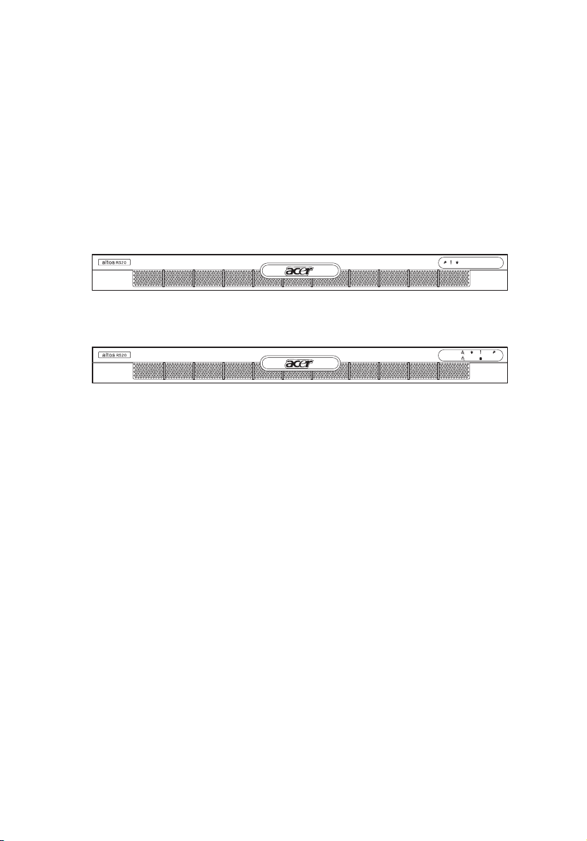
Front bezel
The front bezel provides an interface for system management via
status LED indicators. The light pipes on the backside of the front bezel
allow the system status LEDs to be monitored when the front bezel is
closed. Separate front bezels are available to support systems that use
a mini control panel or standard control panel.
Front bezel supporting mini control panel
Front bezel supporting standard control panel (optional)
The front bezel is removable to allow access to the server’s hard drives,
peripheral device, and control panel. For details on how to remove the
front bezel, see “To remove the front bezel” section on page 41.
7
Page 18

8
1 System tour
Front panel
Item Component Item Component
A Rack handles D Dual-purpose bay*
B Slim-line optical drive bay E 2.5” hot-plug HDD bays
C Mini control panel bay
* The Acer Altos R520 dual-purpose bay supports either the standard control panel or two
2.5” hot-plug HDD drives.
Page 19
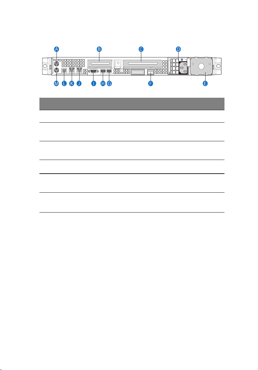
Rear panel
Item Component Item Component
A PS2 mouse port G, H USB 2.0 ports
9
B Low profile PCI expansion
I VGA/monitor port
slot
C Full height PCI expansion slot J, K Gigabit LAN ports (10/100/
1000 Mbps)
D
Power supply module
E Power supply module bay
1
L DB9 serial port A
M PS2 keyboard port
filler panel
F Server management port (10/
100 Mbps) (RJ-45) cover
1 The system power can be configured to support redundant (1+1) and non-redundant (1+0)
configuration.
2 Reserved for remote management of server. This requires the installation of an ARMC/3
module.
2
Page 20
10
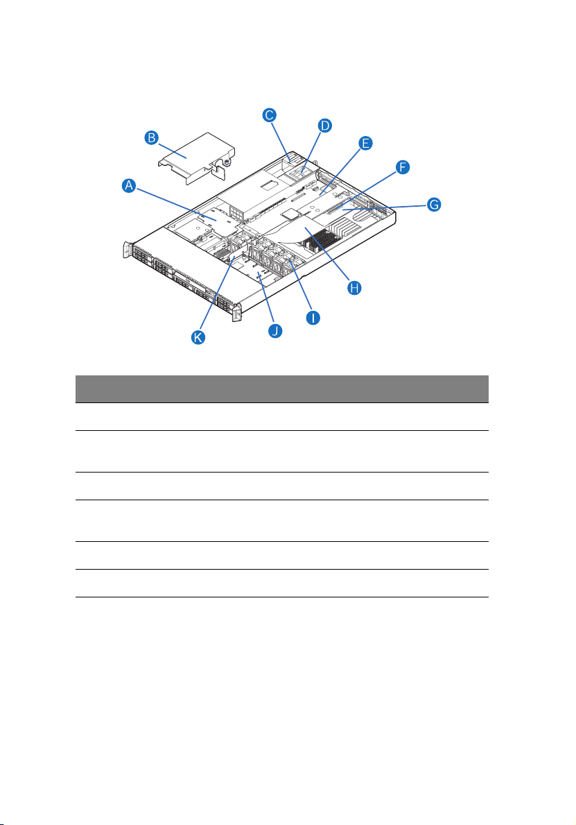
Internal components
Item Component Item Component
A Power distribution board G Memory modules
1 System tour
B Power distribution board
cover
C Power supply module 1 I System fan modules
D Power supply module bay 2
(filler panel shown)
E Riser card assembly K Bridge board
F Mainboard
H CPU air duct
J Mid-plane board (active
mid-plane shown)
Page 21

11
System boards
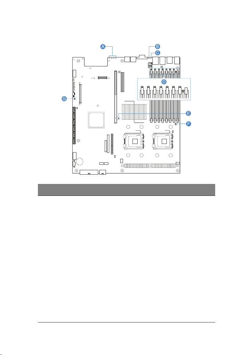
Mainboard
The mainboard becomes accessible once you open the system. It should
look like the figure shown below.
Item Description Item Description
A Rolling BIOS jumper W Battery
B Intel ESB2-E I/O controller X Power supply management
connector
Page 22

12
Item Description Item Description
1 System tour
C Diagnostic POST code
indicators
D Full height PCI riser slot Z SATA 0 connector
E Low profile PCI riser slot AA SATA 1 connector
F USB ports BB SATA 2 connector
G VGA/Monitor port CC SATA 3 connector
H System ID indicator DD SATA 4 connector
I System status indicator EE SATA 5 connector
J Gigabit LAN1 and LAN 2
ports
K Serial B port GG ARMC/3 module connector
L PS2 mouse (top) and
keyboard (bottom) port
M Serial B configuration
jumper
N FBDIMM slots JJ NIC module connector
O Intel 5000P MCH
Y Dual port USB 2.0 connector
FF SATA software RAID
activation key connector
HH System recovery settings
jumper block
II Serial A connector
P CPU socket 1
Q CPU socket 2
R CPU voltage regulator
S Bridge board connector
T IDE optical drive connector
U CPU power connector
V AC power connector
Page 23
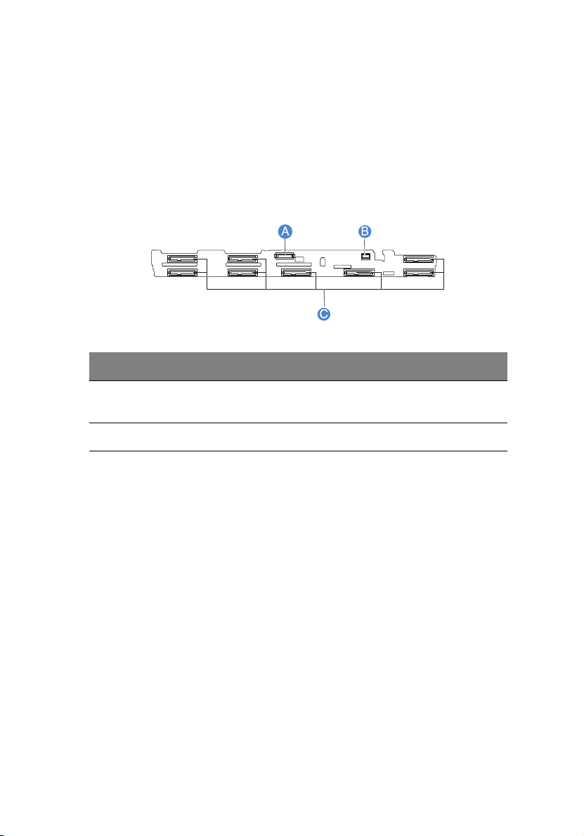
Backplane board
SAS/SATA backplane board
The backplane board installed on the rear side of the hot-plug drive
bay provides support for both SAS and SATA hard drives.
Front view
Item Description Item Description
13
A Slim-line optical drive con-
nector
B Mini control panel connector
CSAS/SATA connectors
Page 24

14
1 System tour
Rear view
Item Description Item Description
A Control panel connector D Mid-plane connectors
B USB connector E Backplane power connector
CIDE connector
Page 25

15
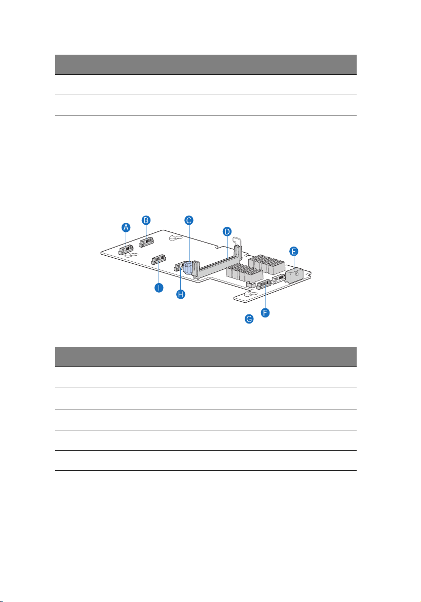
Mid-plane board
The mid-plane boad serves as the primary interface between the
mainboard, backplane, and control panel. It is used to determine the
desired hard drive interface for the system. There are two mid-planes
available for this system: an active mid-plane board and a passive midplane board.
Active mid-plane board (SAS model)
The active mid-plane board is used to provide SAS support. It has an
integrated LSI 1068 SAS controller that provides support for up to eight
hot-plug SAS HDDs. By default, the active mid-plane provides software
RAID levels 0, 1, and 10. With the installation of an optional RAID
activation key and RAID cache, the mid-plane can support hardware
RAID levels 0, 1, 5, 6, 10, and 50.
Note: Mid-plane will support RAID level 6 when available.
B
A
Item Description Item Description
A Fan 2 power connector G RAID BBU (battery backup
B Fan 1 power connector H Mid-plane power connector
C RAID activation key
connector
D Bridge board connector J Fan 4 power connector
C
D
E
F
K
J
I
G
H
unit) connector
I Thumbscrew
Page 26
16
Item Description Item Description
E Fan 6 power connector K Fan 3 power connector
F RAID cache slot
1 System tour
Passive mid-plane board (SATA model)
The passive mid-plane board is used to provide SATA support for the
onboard SATA controller and six SATA ports. The mid-plane also
supports up to six hot-plug SATA HDDs and software RAID levels 0, 1,
and 10. With the installation of an optional SATA software RAID
activation key can support software RAID level 5.
Item Description Item Description
A Fan 2 power connector F Fan 6 power connector
B Fan 1 power connector G
C Thumbscrew H Fan 4 power connector
D Bridge board connector I Fan 3 power connector
E Mid-plane power connector
HBA I
2
C connector
Page 27

17
Control panel
The Acer Altos R520 server supports either the mini control panel,
providing basic functionality, or the standard control panel, which adds
additional server management features. Both control panels utilize a
combination of control buttons, status LED indicators, along with I/O
ports, to centralize system control, monitoring, and accessibility.
Mini control panel
BA DC
GEF
TP02215
Item Component Item Component
A USB 2.0 port E Power/sleep button
B System identification
indicator
C System status indicator G System ID button
D Power/sleep indicator
FNMI button
Page 28

18
Standard control panel (optional)
BA F GEDC
H
I
L JK
Item Component Item Component
A LAN 2 activity indicator G System ID indicator
B LAN 1 activity indicator H System ID button
C Power/sleep button I Reset button
D Power/sleep indicator J USB 2.0 port
1 System tour
E HDD actvity indicator K NMI button
F System status indicator L VGA/monitor port
Page 29

Control panel button function overview
The following table list and describe the function of the control
buttons available on the control panel.
Control button Function
NMI button Puts the server in a halt-state for diagnostic purposes
and allows you to issue a non-maskable interrupt.
After using the interrupt, a memory download can be
performed to determine the cause of the problem.
Reset button Reboots and initializes the system.
Power/sleep button Toggles the system power on and off. This button also
functions as a sleep button if enabled by an ACPIcompliant operating system.
System ID button Toggles the front panel ID LED and the mainboard
system ID LED on and off. The mainboard system ID
LED is visible through the rear of the chassis and
allows you to locate the server you’re working on
from behind a rack of servers.
19
Page 30

20
1 System tour
System LED indicators
This section describes the different LED indicators located on
• Mainboard
• Control panel
• Hot-plug HDD carrier
• LAN port
• Hot-plug power supply module
Page 31
Mainboard diagnostic LED indicators
Item Description Color State Description
21
A Diagnostic
POST code
indicators
During the system boot process,
BIOS executes a number of
platform configuration processes,
each of which is assigned a specific
hex POST code number. As each
configuration routine is started,
BIOS will display the given POST
code to the POST Code Diagnostic
LEDs found on the rear of the
mainboard. To assist in
troubleshooting a system hang
during the POST process, the
diagnostic LEDs can be used to
identify the last POST process to
be executed.
Refer to the Diagnostic POST code
table on page 142. for a complete
description of how these LEDs are
read, and a list of all supported
POST codes.
Page 32

22
Item Description Color State Description
1 System tour
B System ID
indicator
C System
status
indicator
Blue On The system ID buton on the control
panel is activated
Off System identification is disabled
Blink Appropriate hex IPMI “Chassis
Green/
Amber
Green On System booted and ready or
Altern
ating
blink
Blink System degraded
Identify” value has been issued
Pre DC power on - 30-35 second
BMC initialization when AC power
is applied to the system
normal operation
• Unable to use all of the
installed memory
• System loses memory
redundancy when memory
mirroring takes place
• System loses memory
redundancy when memory
sparing takes place
• Redundancy loss such as power
supply or fan
• PCI-E link error
• CPU failure or disabled
• Fan alarm or failure
• Non-critical temperature and
voltage threshold crossed
Page 33

Item Description Color State Description
23
System
status
indicator
(cont.)
D DIMM error
indicators
Amber On Critical or non-recoverable
condition
• DIMM failure when there is one
DIMM present
• Run-time memory
uncorrectable error in
non-redundant mode
• IERR signal asserted
• Processor 1 missing
• Critical temperature
• Power fault
• CPU configuration error
Blink Non-critical condition
• Critical voltage threshold
crossed
• VRD hot asserted
• Fans failed or not present
• Correctable error threshold in
non-sparing and non-mirroring
mode crossed
Off AC power off
On System BIOS disables a DIMM after
it reaches a specified number of
given failures or critical DIMM
failures are detected
E, F CPU error
indicator
G5-volt
standby
present
indicator
On • CPU is disabled
• CPU configuration error is
detected
On • AC power is applied to the
system
• 5 V standby voltage is supplied
to the system by the power
supply
Page 34

24
1 System tour
Control panel LED indicators
The following table list and describe the LED indicators available on
the mini or optional standard control panel.
Indicator Color State Description
LAN1/LAN2
activity
indicator
Power/Sleep
indicator
HDD activity
indicator
System ID
indicator
System
status
indicator
Green On Link between system and network
Blink Network access
Green Off System is not powered on or ACPI S4
or S5 state
On System has power applied to it or ACPI
S0 state
Blink System is in ACPI S1 state (sleep mode)
Green Random
blink
Off No HDD activity
Blue On System identification is active
Off System identification is disabled
Green/
Amber
Green On Running or normal operation
Alternating
blink
Blink System degraded
HDD is active
Pre DC power on - 30-35 second BMC
initialization when AC power is
applied to the system
Amber On Critical or non-recoverable condition
Blink Non-critical condition
Off POST or system stop
Page 35

Hot-plug HDD LED indicators
There are two status LED indicators mounted for each hot-plug HDD
carrier. The table below list the possible drive states.
Indicator Color State Description
25
Hot-plug
HDD activity
indicator
Hot-plug
HDD failure
indicator
Amber Flash HDD is active
Amber +
Green
Green Blink Ongoing hot-plug activity
Off • No HDD is installed
Amber On HDD failure.
Green Blink Ongoing hot-plug activity
Alternate
flash
• HDD is powered on and rebuilding
RAID
• HDD is powered on and is in a fault
condition
• HDD is initiated but has no current
activity
LAN port LED indicators
Indicator Color State Description
Speed
indicator
(left)
Green/
Amber
Green On 100 Mbps connection
Amber On 1000 Mbps connection
Off 10 Mbps connection
Link/
activity
indicator
(right)
Green On Network link is detected
Off No network connection
Blink Transmit or receive activity
Page 36

26
1 System tour
Hot-plug power supply module LED indicator
The table below list and describe the bi-color LED indicator located on
the power supply module.
Indicator Color State Description
Status Off No AC power to the power supply
Green On System has power applied to it
Blink AC power cord is plugged into an
active AC power source
Amber On • No AC power
• Power supply critical event
(i.e, failure, fuse blown, fan
failed, etc.) causing shutdown
Blink Power supply displays warning
event (i.e., high temperature, high
power, high current, slow fan, etc.)
Page 37

System jumpers
Jumper name Settings Function
27
J1D2
Password clear
J1D3
Clear CMOS
J3H1
BIOS select
J1D1
BMC force update mode
J8A3
Serial B port (RJ-45)
1-2 (default)
2-3
1-2 (default)
2-3
1-2
2-3 (default)
1-2 (default)
2-3
1-2
3-4 (default)
Password enabled
Password disabled/cleared
BIOS clear CMOS
Forced CMOS clear
Force lower bank
Normal operation
BMC force update disabled
BMC force update enabled
DCD (Data Carrier Detect) to DTR
(Data Terminal Ready) signal
DSR (Data Set Ready) to DTR signal
Page 38

28
1 System tour
Page 39

2 System setup
Page 40

This chapter gives you instructions on how to set up
the system. Procedures on how to connect
peripherals are also explained.
Page 41

Setting up the system
Pre-installation requirements
Selecting a site
Before unpacking and installing the system, select a suitable site for
the system for maximum efficiency. Consider the following factors
when choosing a site for the system:
• Near a grounded power outlet
• Clean and dust-free
• Stable surface free from vibration
• Well-ventilated and away from sources of heat
• Secluded from electromagnetic fields produced by electrical
devices such as air conditioners, radio and TV transmitters, etc.
Checking the package contents
Check the following items from the package:
• Acer Altos R520 server system
•Acer EasyBUILD
• Acer Altos R520 accessory box
TM
31
If any of the above items are damaged or missing, contact your dealer
immediately.
Save the boxes and packing materials for future use.
Page 42
32
2 System setup
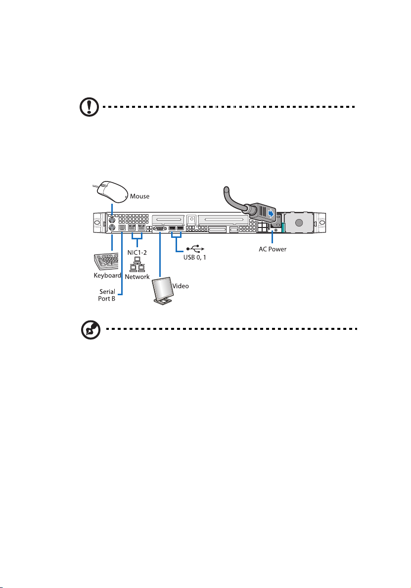
Connecting peripherals
Caution! The server operates on 100-127/200-240 VAC only. Do
not connect the system to an incorrect voltage source.
Refer to the illustration below for specific connection instructions on
the peripherals you want to connect to the system.
Note: Consult the operating system manual for information on
how to configure the network setup.
Page 43

Turning on the system
After making sure that you have properly set up the system and
connected all the required cables, you can now power on the system.
Note: After plugging in the AC power cord, allow system to warm
up for 30 seconds or until the status/fault indicator on the control
panel stops blinking before turning on the system.
Refer to “Control panel” on page 17 for the location of the status/
fault indicator. The location of the status/fault indicator will
depend on the type of control panel installed on your system.
To power on the system:
1 Remove the front bezel. See “To remove the front bezel”section
on page 41.
2 Press the power button on the control panel.
The system starts up and displays a welcome message on the monitor.
After that, a series of POST messages appears.
33
Note: If the system does not turn on or boot after pressing the
power button, go to the next section for the possible causes of the
boot failure.
If the POST finds any problems, the system will emit a beep code
followed by an error message displayed on the monitor. Aside from the
POST messages, you can determine if the system is in good condition
by checking if the following occurred:
• Power indicator on the control panel lights up (green)
• Num Lock, Caps Lock, and Scroll Lock indicators on the keyboard
light up
Page 44

34
2 System setup
Power-on problems
If the system does not boot after you have applied power, check the
following factors that might have caused the boot failure.
• The external power cord may be loosely connected.
Check the power cord connection from the power source to the
power supply module AC input connector on the rear panel. Make
sure that the power cord is properly connected to the power
source and to the AC input connector.
• No power comes from the grounded power outlet.
Have an electrician check your power outlet.
• Loose or improperly connected internal power cables.
Check the internal cable connections. If you are not confident to
perform this step, ask a qualified technician to assist you.
Warning! Make sure all power cords are disconnected from
the electrical outlet before performing this task.
Note: If you have gone through the preceding actions and the
system still fails to boot, ask your dealer or a qualified technician
for assistance.
Page 45

Configuring the system OS
35
The Acer Altos R520 server comes with Acer EasyBUILD
TM
that allows
you to conveniently install your choice of operating system. To start
using EasyBUILD, follow the steps below.
1 Locate the EasyBUILD DVD included in the system package.
2 With the system turned on, gently press the optical drive’s Stop/
Eject button.
3 When the disc tray slides open, insert the EasyBUILD DVD with the
label or title side of the disc facing upward.
Note: When handling the disc, hold it by the edges to avoid
smudges or fingerprints.
4 Gently press the disc down to make sure that it is properly
inserted.
Caution! While pressing the disc, be careful not to bend the disc
tray. Make sure that the disc is properly inserted before closing
the disc tray. Improper insertion may damage both the disc and
the CD-ROM drive.
5 Gently press the drive Stop/Eject button again to close the disc
tray.
6 The Acer EasyBUILD sequence begins. Follow all onscreen
instructions.
For more information, refer to the EasyBUILD Installation guide.
Note: EasyBUILD DVD supports Windows Server 2003, Red Hat
Linux, and SUSE operating system only.
Windows or Linux OS CD is needed when you install the OS with
the EasyBUILD DVD.
Page 46

36
2 System setup
Turning off the system
There are two ways to turn off the server. These include:
• Software power off
If you are using a Windows OS on your server, you can turn off the
server by clicking the Start button, point to Shut Down..., select
Shut down from the drop-down window then click on OK. You
can then turn off all peripherals connected to your server.
If you are using another OS, refer to the OS documentation for
instructions on how to shut down the OS.
• Hardware power off
If you cannot shut down the server using the software, press the
power button for at least four seconds. Quickly pressing the
button may put the server in a Suspend mode only.
Page 47

3 System upgrade
Page 48

This chapter discusses the precautionary measures
and installation procedures you need to know to
upgrade the system.
Page 49

Installation precautions
Before you install any server component, we recommend that you read
the following sections. These sections contain important ESD
precautions along with pre-installation and post-installation
instructions.
ESD precautions
Electrostatic discharge (ESD) can damage the processor, disk drives,
expansion boards, motherboard, memory modules and other server
components. Always observe the following precautions before you
install a server component:
1 Do not remove a component from its protective packaging until
you are ready to install it.
2 Wear a wrist grounding strap and attach it to a metal part of the
server before handling components. If a wrist strap is not
available, maintain contact with the server throughout any
procedure requiring ESD protection.
39
Pre-installation instructions
Perform the steps below before you open the server or before your
remove or replace any component:
1 Turn off the system and all the peripherals connected to it.
2 Unplug all cables from the power outlets.
3 Place the system unit on a flat, stable surface.
4 Open the system according to the instructions on page 41.
5 Follow the ESD precautions described in this section when
handling a server component.
6 Remove any hardware structure or cable that block access to the
component you must replace or upgrade.
See the following sections for specific installation instructions on the
component you want to install.
Page 50

40
Warning! Failure to properly turn off the server before you
start installing components may cause serious damage. Do
not attempt the procedures described in the following
sections unless you are a qualified service technician.
3 System upgrade
Post-installation instructions
Perform the steps below after installing a server component.
1 See to it that all components are installed according to the
described step-by-step instructions.
2 Reinstall all components or cable that have been previously
removed.
3 Reinstall the top cover.
4 Reinstall the front bezel.
5 Connect the necessary cables.
6 Turn on the system.
Page 51

Opening the server
Caution! Before you proceed, make sure that you have turned
off the system and all peripherals connected to it. Read the “Preinstallation instructions” on page 39.
You need to open the server before you can install additional
components. The front bezel and top cover are removable to allow
access to the system’s internal components. Refer to the following
sections for instructions.
Removing and installing the front bezel
To remove the front bezel:
1 If necessary, remove any cables attached to the control panel.
2 Grasp the front bezel at the outer edge and pull it straight out.
41
Page 52

42
3 System upgrade
To install the front bezel:
1 Line up the center notch on both ends of the bezel with the center
guide on the rack handles.
2 Slide the front bezel onto the chassis until it clicks into place.
Page 53

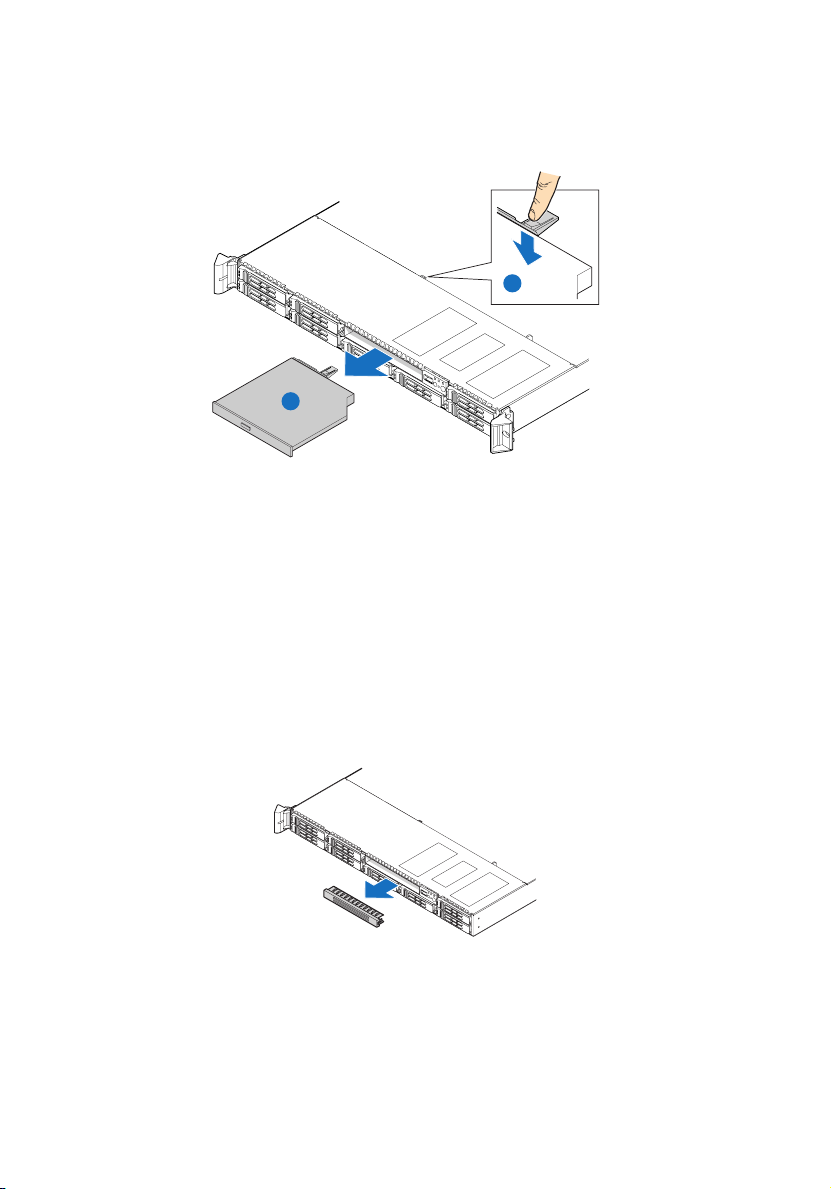
Removing and installing the top cover
To remove the top cover:
1 Observe the ESD precautions and pre-installation instructions
described on page 39.
2 Remove the screw located on the top cover (A).
3 Press and hold the blue release button (B), then slide the cover
toward the back of the chassis until the cover disengage with the
slots on the chassis (C).
4 Lift the top cover away from the server and put it aside for
reinstallation later.
43
Page 54

44
3 System upgrade
To install the top cover:
1 Observe the ESD precautions and pre-installation instructions
described on page 39.
2 Place the top cover on the chassis so that the tabs on the cover
align with the slots on the chassis .
3 Slide the top cover toward the front of the chassis until it is fully
closed (A).
4 Replace the screw on the top cover (B).
Page 55

Removing and installing the CPU air duct
Caution! Always operate your server with the CPU air duct
installed to ensure reliable and continued operation.
To remove the CPU air duct:
You will need to remove the CPU air duct to perform the following
procedures:
• Removing and installing a CPU air baffle
• Removing and installing the PCI riser assembly
• Removing and installing the PCI card
• Removing and installing a CPU
• Removing and installing a memory module
1 Observe the ESD precautions and pre-installation instructions
described on page 39.
2 Lift the CPU air duct from the chassis.
45
Page 56

46
3 System upgrade
To install the CPU air duct:
1 Observe the ESD precautions and pre-installation instructions
described on page 39.
2 Place the CPU air duct over the two processor sockets. The front
edge of the air duct should touch the front fan module and the
top of the installed air duct should be flush with the top of the PCI
riser assembly.
Caution! Do not pinch or unplug cables that may be near or
under the air duct.
3 Observe the post-installation instructions described on page 40.
Page 57

Removing the CPU air dam
To remove the CPU air dam:
Important: Do not remove the CPU air dam from the CPU air duct
except when installing a second CPU to the system. The air dam
ensures proper air flow when a single CPU is installed to the
system.
Do not remove the memory air deflector.
1 Observe the ESD precautions and pre-installation instructions
described on page 39.
2 Turn the CPU air duct over.
3 Remove the air dam by sliding slotted holes off duct pins.
47
TP02227
4 Store it in a protective packaging.
5 To install a second CPU to your system, see “Upgrading the CPU”
section on page 61 for detailed instructions.
6 Observe the post-installation instructions described on page 40.
Page 58

48
3 System upgrade
Removing and installing the power distribution board cover
To remove the power distribution board cover:
You will need to remove the power distribution board cover to
perform the following procedures:
• Removing and installing the RAID activation key and RAID cache
• Removing and installing a RAID BBU
1 Observe the ESD precautions and pre-installation instructions
described on page 39.
2 Loosen the thumbscrew that secures the cover to the chassis (A).
3 Pull up the cover to remove it (B).
A
B
TP02228
4 Observe the post-installation instructions described on page 40.
Page 59

To install the power distribution board cover:
1 Observe the ESD precautions and pre-installation instructions
described on page 39.
2 Lower the power distribution board cover to the chassis (A).
3 Tighten the thumbscrew to secure the cover to the chassis (B).
B
A
TP02229
4 Observe the post-installation instructions described on page 40.
49
Page 60

50
3 System upgrade
Configuring the storage devices
The system supports 2.5-inch storage devices. It accommodates slimline optical drives and depending on system model, can support up to
six 2.5-inch hot-plug SATA hard disk drives or eight hot-plug SAS hard
disk drives.
Caution! To maintain proper system cooling, filler panels must be
installed if a device is not replaced.
Removing and installing a hard disk drive
Note: Use only Acer-qualified SAS or SATA HDDs. To purchase a
SAS or SATA HDD, contact your local Acer representative.
Caution! To ensure proper airflow and server cooling, all drive
bays must contain either a carrier with a hard drive installed in it
or a hard disk carrier cover.
Determining drive status
Each HDD carrier features two status LED indicators to display the hard
drive status. If you are replacing a failed HDD, determine which drive
has failed by checking the drive status LED. For more information on
how to determine the drive status, refer to “Hot-plug HDD LED
indicators” on page 25.
Page 61

51
To remove a HDD:
1 Observe the ESD precautions described on page 39.
2 If you are removing a failed HDD, determine which drive has failed
by checking the drive status LEDs.
3 Press the green HDD carrier latch to open the drive (A).
4 Pull out the lever and slide the carrier from the chassis (B).
B
A
5 Place the HDD carrier on a clean, static-free work surface.
6 If you are replacing a hard disk, remove the four screws that secure
the hard disk to the HDD carrier, then remove the disk from the
HDD carrier.
7 Keep the screws for later HDD installation.
Page 62

52
3 System upgrade
To install a HDD:
Note: To puchase a HDD carrier, contact your local Acer
representative.
1 Perform steps 1 to 4 listed on the “To remove a HDD” section on
page 51.
2 Remove the four screws that secure the air baffle to the HDD
carrier (A).
3 Remove the air baffle from the HDD carrier (B).
4 Save the air baffle and screws for later use.
5 Remove the HDD from its protective packaging.
6 Install a hard disk on the HDD carrier, then secure it with the four
screws (A) that came with the HDD carrier (B).
B
A
TP02231
7 With the lever still extended, slide the HDD carrier all the way into
the drive bay (A). Do not push on the lever until it begins to close
by itself.
Page 63

53
8 When the lever begins to close by itself, push on it to lock the drive
assembly into place (B).
A
B
Removing and installing a slim-line optical drive
Note: The slim-line optical drive is not hot-pluggable. Before
removing or replacing the drive, you must first power down the
server, unplug the AC power cord from the system, and turn off all
peripherals devices connected to the server.
Caution! To maintain proper system cooling, a filler panel must
be installed if a device is not installed in the bay.
To remove a slim-line optical drive:
1 Observe the ESD precautions and pre-installation instructions
described on page 39.
Page 64
54
3 System upgrade
2 Press the blue release lever to unlock the optical drive tray (A) and
slide the optical drive tray out through the front of the server (B).
A
B
TP02261
3 If no device will be installed in the drive bay, install the filler panel
in the drive bay.
If installing a new optical drive, see succeeding section.
To install a slim-line optical drive:
1 Observe the ESD precautions and pre-installation instructions
described on page 39.
2 If necessary, remove the old optical drive. See previous section.
3 If a filler panel is installed, remove it from the drive bay.
4 Remove the new drive from its protective packaging.
Page 65

5 Install the plastic guide on the rear of the optical device, then
secure it with the two screws that came with the optical drive kit.
TP02233
6 Slide the optical drive tray into the front opening in the server.
Make sure the back end of the plastic guide plugs into the
matching connector on the backplane board.
7 Verify that the blue release lever on the tray locks into place.
8 Observe the post-installation instructions described on page 40.
55
Page 66

56
3 System upgrade
Removing and installing a PCI riser assembly
Note: The PCI riser assembly includes an intrusion switch that
engages the system cover. The intrusion switch is provided to
allow server management software to monitor removal of the top
cover from the server.
Caution! The PCI riser assembly must be installed to maintain
proper airflow inside the server.
This section explains how to access the PCI riser assembly and remove
and install PCI cards.
To remove the PCI riser assembly:
1 Observe the ESD precautions and pre-installation instructions
described on page 39.
2 Remove the CPU air duct. Perform the instructions described in “To
remove the CPU air duct” section on page 45.
3 Diconnect any cables attached to an installed PCI card.
4 Grasp both riser latches with thumb and forefinger, then pull up to
release the riser assembly.
Page 67

5 Lift the riser assembly from the chassis.
TP02236
6 Place the riser assembly on a clean, static-free work surface.
7 If you need to replace PCI cards. See “Removing and installing a
PCI card” on page 58.
8 Observe the post-installation instructions described on page 40.
57
Page 68

58
3 System upgrade
To install the PCI riser assembly:
1 Observe the ESD precautions and pre-installation instructions
described on page 39.
2 Lower the PCI riser assembly (A), aligning the four hooks on the
back edge of the riser assembly with the matching slots on the rear
of the chassis (B).
3 Press down on the assembly until the four hooks on the rear of the
riser assembly engage the chassis rear panel slots. The riser cards
will seat into the matching sockets on the mainboard.
4 Connect the cables to the installed PCI card.
5 Observe the post-installation instructions described on page 40.
Removing and installing a PCI card
To remove a PCI card:
1 Observe the ESD precautions and pre-installation instructions
described on page 39.
2 Remove the CPU air duct. Perform the instructions described in “To
remove the CPU air duct” section on page 45.
3 Remove the PCI riser assembly from the server. See “To remove the
PCI riser assembly” section on page 56.
4 Open the rear retention clip by pushing the blue slide upward and
rotating clip to the fully open position.
Page 69

5 When removing a full height PCI card, open the full length PCI
card retention clip on the front of the riser assembly by rotating it
90 degrees outward.
Note: The install sequence for low profile PCI cards on the
opposite side of the riser assembly is the same.
6 Pull up the card to remove it, then store the card in an antistatic
protective wrapper.
A
B
TP02241
7 Observe the post-installation instructions described on page 40.
To install a PCI card:
59
Note: When installing PCI-X cards into the full height riser board,
the cards must be installed starting with the top slot first,
followed by the middle and then the bottom. Any card populated
in the bottom PCI slot will cause the bus to operate at 66 MHz.
1 Observe the ESD precautions and pre-installation instructions
described on page 39.
2 Remove the CPU air duct. Perform the instructions described in “To
remove the CPU air duct” section on page 45.
3 Remove the PCI riser assembly from the server. See “To remove the
PCI riser assembly” section on page 56.
4 Open the rear retention clip by pushing the blue slide upward (A)
and rotating clip to the fully open position.
Page 70

60
3 System upgrade
5 When installing a full height PCI card, open the full length PCI card
retention clip on the front of the riser assembly by rotating it 90
degrees outward (B).
6 Remove the filler panel, if installed.
7 Insert the PCI card into the selected slot (C). Make sure the card is
properly seated.
B
A
C
TP02240
8 Close both retention clips.
9 Observe the post-installation instructions described on page 40.
Page 71

61
Upgrading the CPU
The server supports two dual-core or quad-core Intel Xeon processors
5000 sequence with system bus speeds of 667 MHz, 1066 MHz or 1333
MHz, and core frequencies starting at 1.6 GHz.
CPU upgrading guidelines
When installing CPUs the following rules must be observed:
• Use only Acer-qualified CPUs.
• Each CPU socket include a CPU and heat sink.
• When two CPUs are installed, both should have identical revision,
core voltage, and bus/core speed values.
• When only one CPU is installed, it must be installed in CPU 1
socket.
• System is designed to provide up to 130 W of current per
processor. Processors with higher current requirements are not
supported.
To install a CPU:
1 Observe the ESD precautions and pre-installation instructions
described on page 39.
Warning! The heat sink becomes very hot when the system
is on. NEVER touch the assembly with any metal or with
your hands.
2 Remove the CPU air duct. Perform the instructions described in “To
remove the CPU air duct” section on page 45.
3 If installing a second CPU, remove the CPU air dam first. See
“Removing the CPU air dam” section on page 47.
4 Locate the processor socket.
Page 72

62
3 System upgrade
5 Push the socket retainer lever handle down and away from the
socket to release it (A), then pull the lever to a fully open, upright
position (B).
6 Push the rear tab with your finger tip to bring the front end of the
load plate up slightly (A).
7 Lift the load plate (B).
8 Remove the CPU from its protective packaging.
9 Position the CPU over the socket (A), making sure the CPU cutouts
match the socket notches, then insert the CPU into the socket (B).
Caution! The underside of the CPU has components that may
damage the socket pins if installed improperly. CPU must align
correctly with socket opening before installation. DO NOT drop
processor into the socket.
Page 73

10 Remove the protective socket cover by grasping the socket cover
tab (A) and pulling it away from the load plate (B).
63
11 Store the protective socket cover for future use.
12 Close the load plate (A), then press the retainer lever down to lock
the load plate in place (B, C).
Page 74

64
3 System upgrade
13 If the heat sink does not have thermal grease on the bottom, apply
thermal grease to the heat sink base.
14 Install the heatsink and fan
Caution! The heat sink has a thermal interface material (TIM) on
the underside. Use caution so that you do not damage the TIM.
(1) If a protective film is installed on the TIM, remove it.
(2) Set the heat sink over the processor, aligning the four captive
screws with the four screw posts surrounding the processor.
(3) Loosely screw in the captive screws on the heat sink corners in
a diagonal manner.
Note: Do not fully tighten one screw before tightening another.
(4) Gradually and equally tighten each captive screw until each is
firmly tightened.
3
2
1
4
TP02328
15 Observe the post-installation instructions described on page 40.
Page 75

65
To remove a CPU:
If you are replacing a CPU on the system, the heat sink must first be
removed.
Important: Before removing a CPU from the mainboard, make
sure to create a backup file of all important data.
1 Observe the ESD precautions and pre-installation instructions
described on page 39.
Warning! The heat sink becomes very hot when the system
is on. NEVER touch the assembly with any metal or with
your hands.
2 Remove the CPU air duct. Perform the instructions described in “To
remove the CPU air duct” section on page 45.
3 Locate the CPU you want to remove.
4 Remove the heat sink.
(1) Loosen the four captive screws on the heat sink.
(2) Twist the heat sink lightly to break the seal between the
heatsink and the processor.
Page 76

66
3 System upgrade
(3) Lift the heat sink from the processor.
Caution! If it does not pull up easily, twist the heat sink again. Do
not force the heat sink from the processor. Doing so could damage
the processor.
(4) Place the heat sink upside down on a flat surface.
Note: Wipe off the thermal grease from both the heat sink and
processor using an alcohol pad.
5 Pull the CPU socket retainer lever handle down and away from the
socket to release it.
6 Lift the load plate.
7 Pull out the CPU from the socket, then store it in an anti-static bag.
8 If installing a replacement processor, see “To install a CPU”.
9 Observe the post-installation instructions described on page 40.
Page 77

67
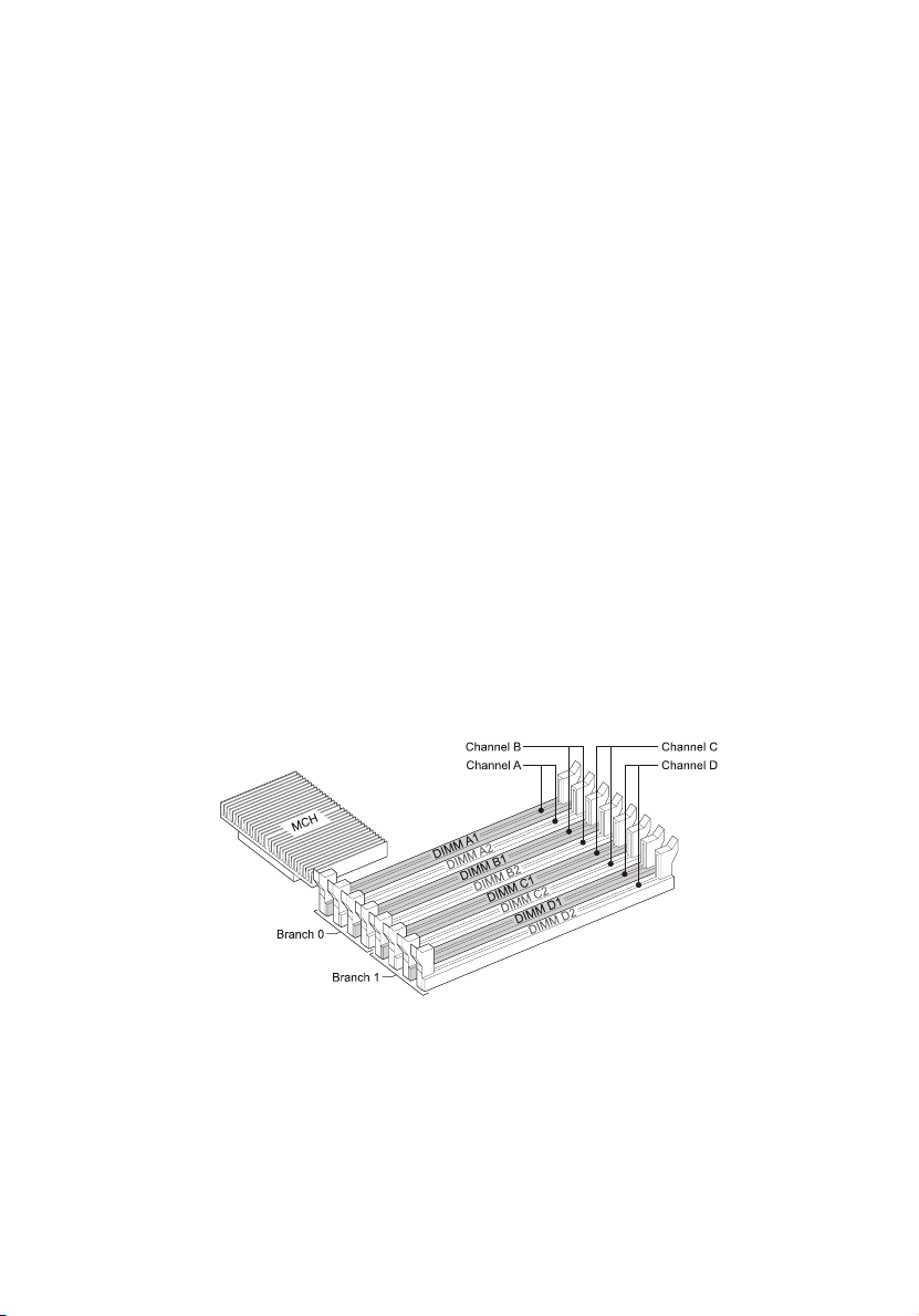
Upgrading the system memory
Acer Altos R520 server supports eight DDR2 fully buffered DIMM slots
with four FBDIMM memory channels. Each channel can support up to 2
dual ranked DDR2 FBDIMMs. The memory channels are organized in to
two branches for support of mirrored memory configuration. Up to 8
FBDIMMs or a maximum memory size of 32 GB physical memory in
standard non-mirrored mode and 16 GB physical memory in a mirrored
configuration are supported by the server.
On the server, a pair of channels becomes a branch where each branch
consists of:
•Branch 0
• Channel A - DIMMA1 and DIMMA2
• Channel B - DIMMB1 and DIMMB2
•Branch 1
• Channel C - DIMMC1 and DIMMC2
• Channel D - DIMMD1 and DIMMD2
Page 78

68
3 System upgrade
Memory module installation guidelines
The following rules apply when installing fully-buffered memory
modules to the server:
• The system must have a minimum of one 512 MB FBDIMMs
installed. When installing additional memory, refer to the tables
on “Memory module population order” on page 69 for proper
population order.
• Use only DDR2 FBDIMMs. Other DIMMs will not fit into the socket.
Attempts to force a non-DDR2 FBDIMM into a socket will damage
or the slot or the FBDIMM.
• Hold FBDIMMs only by the edges. Do not touch the components or
gold edge connectors.
• Install FBDIMMs with gold-plated edge connectors only.
Memory module population guidelines
The following configuration rules must be observed when populating
memory modules:
• In a minimum memory configuration, the FBDIMM should be
installed in DIMM A1 slot.
• Install FBDIMM pairs in the following order:
• Channel A: DIMM slots A1 and A2
• Channel B: DIMM slots B1 and B2
• Channel C: DIMM slots C1 and C2
• Channel D: DIMM slots D1 and D2
• FBDIMMs within a given channel must be identical with respect to
size, speed, and organization.
Page 79

69
Memory module population order
The tables below list the suggested DDR2 FBDIMM module population
for standard, mirrored or sparing configuration.
Standard configuration
Branch 0 Branch 1
Channel A Channel B Channel C Channel D
DIMM A1 DIMM A2 DIMM B1 DIMM B2 DIMM C1 DIMM C2 DIMM D1 DIMM D2
512 MB
512 MB 512 MB
512 MB 512 MB 512 MB 512 MB
512 MB 512 MB 512 MB 512 MB 512 MB 512 MB
512 MB 512 MB 512 MB 512 MB 512 MB 512 MB 512 MB 512 MB
1 GB
1 GB 1 GB
1 GB 1 GB 1 GB 1 GB
1 GB 1 GB 1 GB 1 GB 1 GB 1 GB
1 GB 1 GB 1 GB 1 GB 1 GB 1 GB 1 GB 1 GB
2 GB
2 GB 2 GB
2 GB 2 GB 2 GB 2 GB
2 GB 2 GB 2 GB 2 GB 2 GB 2 GB
2 GB 2 GB 2 GB 2 GB 2 GB 2 GB 2 GB 2 GB
Mirrored configuration
Branch 0 Branch 1
Channel A Channel B Channel C Channel D
DIMM A1DIMM A2DIMM B1DIMM B2DIMM C1DIMM C2DIMM D1DIMM
512 MB 512 MB 512 MB
512 MB 512 MB 512 MB 512 MB 512 MB
1 GB 1 GB 1 GB
1 GB 1 GB 1 GB 1 GB 1 GB
2 GB 2 GB 2 GB
2 GB 2 GB 2 GB 2 GB 2 GB
(Mirror)
(Mirror)
(Mirror)
(Mirror)
(Mirror)
(Mirror)
512 MB
(Mirror)
1 GB
(Mirror)
2 GB
(Mirror)
512 MB
(Mirror)
512 MB
(Mirror)
1 GB
(Mirror)
1 GB
(Mirror)
2 GB
(Mirror)
2 GB
(Mirror)
D2
512 MB
(Mirror)
1 GB
(Mirror)
2 GB
(Mirror)
Total Memory
Physical
Memory
Detected
by OS
2 GB 1 GB
4 GB 2 GB
4 GB 2 GB
8 GB 4 GB
8 GB 4 GB
16 GB 8 GB
Page 80

70
Sparing configuration
3 System upgrade
Branch 0 Branch 1
Channel A Channel B Channel C Channel D
DIMM A1DIMM A2DIMM B1DIMM B2DIMM C1DIMM C2DIMM D1DIMM
512 MB
512 MB 1 GB 512 MB
(Sparing)
512 MB
512 MB 512 MB
(Sparing)
512 MB
512 MB 512 MB
(Sparing)
1 GB
1 GB 2 GB 1 GB
(Sparing)
1 GB
1 GB 1 GB
(Sparing)
1 GB
1 GB 1 GB
(Sparing)
2 GB
2 GB 4 GB 2 GB
(Sparing)
2 GB
2 GB 2 GB
(Sparing)
2 GB
2 GB 2 GB
(Sparing)
512 MB 2 GB 1 GB
(Sparing)
512 MB 512 MB
(Sparing)
1 GB 4 GB 2 GB
(Sparing)
1 GB 1 GB
(Sparing)
2 GB 8 GB 4 GB
(Sparing)
2 GB 2 GB
(Sparing)
(Sparing)
(Sparing)
(Sparing)
512 MB 512 MB
1 GB 1 GB
2 GB 2 GB
D2
512 MB 4 GB 2 GB
(Sparing)
1 GB 8 GB 4 GB
(Sparing)
2 GB 16 GB 8 GB
(Sparing)
Total Memory
Physical
Memory
Detected
by OS
Memory configuration overview
The system supports the following memory configuration that allow
flexibility in performance, redundancy, and ability to upgrade.
• Standard configuration
• Memory mirroring
• Memory sparing
Memory mirroring and memory sparing features are mutually
exclusive, only one of these memory modes can be enabled at one time
and not both at the same time.
Page 81
71
Standard memory configuration
The system is capable of supporting a minimum of only one FBDIMM
installed on the DIMM A1 slot. However, for system performance
reasons, we recommend that at least two memory modules must be
installed per branch. The modules must cover the same slot position on
both channels and FBDIMM pairs must be identical with respect to size,
speed, and organization. FBDIMMs that cover adjacent slot positions
do not need to be identical.
When adding four FBDIMMs to a standard non-mirrored
configuration, the memory modules must be populated in DIMM slots
A1 and B1 first then DIMM slots C1 and D1. It allows both memory
branches to operate in parallel and simultaneously to achieve
equivalent performance.
Mirrored memory configuration
Memory mirroring is implemented in the MCH and the system BIOS.
You can configure the system to maintain mirrored copy of the data in
memory. When operating in mirrored mode, both branches operate in
lock step. In mirrored mode, branch 1 contains a replicate copy of the
data in branch 0. The minimum FBDIMM configuration to support
memory mirroring is four FBDIMMs, populated as shown in the figure
below:
All four memory modules must be identical with respect to size, speed,
and organization.
Page 82

72
3 System upgrade
To upgrade to a four FBDIMM mirrored memory configuration, four
additional FBDIMMs must be added to the system. All four memory
modules in the second set must be identical to the first with the
exception of speed. The memory controller hub (MCH) will adjust to
the low-speed FBDIMM memory.
Note: After upgrading system memory to this feature, the
memory RAS setting in the BIOS setup must be set to Mirroring
configuration. Refer to the BIOS setup’s Configure Memory RAS
and Performance screen on page 101 for more information.
Memory sparing configuration
The system provides FBDIMM sparing capabilities. Sparing is a RAS
feature that involves configuring a FBDIMM to be placed in reserve so
it can be use to replace a failed FBDIMM.
Note: FBDIMM sparing occurs within a given bank of memory and
is not supported across branches.
The system supports two types of memory sparing configurations:
• Single branch mode sparing
In single branch mode sparing the following population rules must
be observed:
• DIMM slots A1 and B1 or DIMM slots A2 and B2 must be
identical in organization, speed, and speed
• DIMM slots A1 and A2 or DIMM slots B1 and B2 need not be
identical in organization, size and speed
• Sparing should be enabled in the BIOS setup utility
• System BIOS will configure rank sparing mode.
• The largest memory size among the DIMM pairs (DIMM_A1,
DIMM_B1) and (DIMM_A2, DIMM_B2) will be selected as the
spare pair unit.
• Dual branch mode sparing
Dual branch mode sparing requires that all eight FBDIMM slots be
populated and must comply with the following population rules:
Page 83

73
• The following FBDIMM slots must be identical in organization,
size and speed.
• DIMM slots A1 and B1 • DIMM slots C1 and D1
• DIMM slots A2 and B2 • DIMM slots C2 and D2
• The following DIMM slots need not be identical in
organization, size and speed.
• DIMM slots A1 and A2 • DIMM slots C1 and C2
• DIMM slots B1 and B2 • DIMM slots D1 and D2
• Sparing should be enabled in the BIOS setup utility
• BIOS will configure rank sparing mode.
• The largest memory size among the DIMM pairs (DIMM_A1,
DIMM_B1) and (DIMM_A2, DIMM_B2) and (DIMM_C1,
DIMM_D1) and (DIMM_C2, DIMM_D2), will be selected as the
spare pair units.
Note: After upgrading system memory to this feature, the
memory RAS setting in the BIOS setup must be set to Sparing
configuration. Refer to the BIOS setup’s Configure Memory RAS
and Performance screen on page 101 for more information.
To install FBDIMMs:
Caution! Use extreme care when installing a FBDIMM. Applying
too much pressure can damage the connector. FBDIMMs are keyed
and can be inserted in only one way.
Note: The number labels next to the FBDIMM slots correspond to
proper installation sequence.
1 Observe the ESD precautions and pre-installation instructions
described on page 39.
2 Remove the CPU air duct. Perform the instructions described in “To
remove the CPU air duct” section on page 45.
3 Locate the DIMM slots on the mainboard.
Page 84

74
3 System upgrade
4 Open the clips on the DIMM slot(s) (A).
5 Align (B) then insert the FBDIMM into the socket (C).
6 Press the holding clips inward to lock the FBDIMM in place (D).
Note: The DIMM slot is slotted to ensure proper installation. If
you insert a FBDIMM but it does not fit easily into the socket, you
may have inserted it incorrectly. Reverse the orientation of the
FBDIMM and insert it again.
7 Observe the post-installation instructions described on page 40.
To remove FBDIMMs:
Before you can install a new DIMM in a socket, first remove any
previously installed DIMM from that socket.
Important: Before removing any DIMM from the mainboard,
make sure to create a backup file of all important data.
Page 85

75
Caution! Use extreme care when removing DIMMs. Too much
pressure can damage the connector. Apply only enough pressure
on the plastic levers to release the DIMM.
1 Observe the ESD precautions and pre-installation instructions
described on page 39.
2 Press the holding clips on both sides of the DIMM slot outward to
release the DIMM (A).
3 Gently pull the DIMM upward to remove it from the DIMM slot
(B).
4 Observe the post-installation instructions described on page 40.
To reconfigure the system memory:
The system automatically detects the amount of memory installed. Run
the BIOS setup to view the new value for total system memory and
make a note of it.
Page 86

76
3 System upgrade
Installing and removing a power supply module
The server has two power supply module bays on the rear panel that
accept hot-plug power supply modules. The system ships out with only
a single power supply module installed. You have the option to
purchase an extra power supply module to provide the system with a
redundant power source. A redundant power configuration enables a
fully-configured system to continue running even if one power supply
module fails.
WARNING! To reduce the risk of personal injury or damage to
the equipment, the installation of power supply modules
should be referred to individuals who are qualified to service
server systems and are trained to deal with equipment capable
of generating hazardous energy levels.
WARNING! To reduce the risk of personal injury from hot
surfaces, observe the thermal labels on each power supply
module. You can also consider wearing protective gloves.
WARNING! To reduce the risk of personal injury from electric
shock hazards, do not open the power supply modules. There
are no serviceable parts inside the module.
Caution! Electrostatic discharge can damage electronic
components. Make sure that you are properly grounded before
handling a power supply module.
Caution! Due to chassis airflow disruption, a power supply bay
should never be vacant for more than two minutes when the
server is powered on. Exceeding five minutes might cause the
system to exceed the maximum acceptable temperature and
possibly damage the system components.
Caution! The power supply is only hot-pluggable if you have a
redundant system with two power supplies installed. If you
only have one power supply installed, before removing or
replacing the power supply, you must first take the server out
of service, turn off all peripheral devices connected to the
system, turn off the system by pressing the power button, and
unplug the AC power cord from the system or wall outlet.
Page 87

77
To install a second power supply module:
1 Remove the top cover. Perform the instructions described in “To
remove the top cover” section on page 43.
2 If a filler panel is installed, use the finger hole to remove the filler
panel out of the bay (A).
TP02242
3 Insert the power supply module into the right bay, labeled power
supply bay 2, until it locks into place.
TP02243
4 Verify that the LED on the power supply are functioning. Refer to
the “Hot-plug power supply module LED indicator” on page 26
for more information.
Page 88

78
3 System upgrade
To remove a power supply module:
Caution! Power supply hot-plug operations should be performed
only if a failure occurs in the power supply.
1 If there are more than one power supply modules installed,
determine which power supply module has failed. Refer to the
“Hot-plug power supply module LED indicator” on page 26 for
more information.
2 Remove the AC power cord from the power supply being replaced.
3 Press the power supply latch to release the power supply module
from the chassis (A).
4 Use the handle to pull the power supply module out of the server
(B).
B
A
TP02244
5 Install a new power supply module or install a filler panel to the
empty bay.
Page 89

79
Removing and installing an ARMC/3 module
The optional ARMC/3 module provides server management firmware
and functionality to the system.
To remove an ARMC/3 module:
1 Observe the ESD precautions and pre-installation instructions
described on page 39.
2 Remove the CPU air duct. Perform the instructions described in “To
remove the CPU air duct” section on page 45.
3 Remove the NIC module.
a Pull up the module to remove it from the connector.
b Remove the three standoffs from the mainboard, then keep
the standoffs for later NIC module installation.
4 Hold the module both by the finger grip loop and by the opposite
corner (A).
Caution! Do not bend or twist the module.
Page 90

80
3 System upgrade
5 Pull up the module to remove it from the connector (B).
6 Observe the post-installation instructions described on page 40.
To install an ARMC/3 module:
Note: Prior to installing the ARMC/3 module module, you must
remove the server management port cover module cover on the
rear of the server.
1 Observe the ESD precautions and pre-installation instructions
described on page 39.
2 Remove the CPU air duct. Perform the instructions described in “To
remove the CPU air duct” section on page 45.
3 Insert the standoff into the hole in the ARMC/3 module. The
standoff installs on the bottom side of the module (A).
Page 91

4 Attach the module to the ARMC/3 module connector on the
mainboard and snap the standoff into the matching hole on the
mainboard (B).
5 Install the NIC module.
a Install the three standoffs to the mainboard.
b Attach the module to the NIC module connector on the
mainboard and matching standoff holes.
81
6 Observe the post-installation instructions described on page 40.
Page 92

82
3 System upgrade
Installing and removing the SAS hardware RAID components
The system supports SAS hardware RAID through the active mid-plane
and backplane board. The server platform supports SAS hardware RAID
0, 1, 5, 6 (when available), 10, and 50 levels. Functionality for SAS
hardware RAID is enabled by using the following components:
• RAID activation key and RAID cache
The RAID activation key works in conjunction with the RAID cache
to provide hardware RAID.
• RAID BBU
If power to the storage I/O processor drops below specifications,
the RAID BBU maintains the contents of the DIMM by keeping the
DIMM in self-refresh mode until power is restored. After power is
restored, data can be safely written to drives, maintaining the
integrity of the disk array.
Installing and removing the RAID activation key and RAID cache
To install the RAID activation key and RAID cache:
1 Observe the ESD precautions and pre-installation instructions
described on page 39.
2 Remove the power distribution board cover. Perform the
instructions described in “To remove a power distribution module
cover” section on page 48.
3 Remove the RAID activation key from its protective packaging.
4 Align then insert the activation key into the RAID activation key
connector on the active mid-plane board (A).
5 Locate the RAID cache memory (DDR-2) slot on the active
mid-plane board.
Page 93

6 Open the clips on the slot (B).
7 Align then insert the RAID cache into the slot (C).
A
83
B
B
C
AF000904
8 Press the holding clips inward to lock the RAID cache in place.
9 Observe the post-installation instructions described on page 40.
To remove the RAID activation key and RAID cache:
1 Observe the ESD precautions and pre-installation instructions
described on page 39.
2 Remove the power distribution board cover. Perform the
instructions described in “To remove a power distribution module
cover” section on page 48.
3 Insert the tip of a small flat-bladed screwdriver under the plastic
tab on the retainer holding the activation key to the active midplane board.
4 Gently push down to detach the activation key (A).
5 Press the holding clips on both sides of the slot outward to release
the RAID cache (B).
Page 94

84
3 System upgrade
6 Gently pull the RAID cache upward to remove it from the slot (C).
A
B
B
C
AF000905
7 Close the clips.
8 Store the RAID activation key and RAID cache in an anti-static bag.
9 Observe the post-installation instructions described on page 40.
Installing and removing the RAID BBU
To install the RAID BBU:
1 Observe the ESD precautions and pre-installation instructions
described on page 39.
2 Remove the power distribution board cover. Perform the
instructions described in “To remove a power distribution module
cover” section on page 48.
3 Open the BBU case lid (A), then connect the power cable to the
power cable connector inside the battery pack (B).
Page 95

85
4 Close and latch the BBU case lid.
5 Align the two hooks on the underside of the RAID BBU with the
matching chassis tabs, then slide toward the power supply to lock
into place (C).
6 Connect the power cable to the rear of the BBU and the RAID BBU
connector on the active mid-plane board (D).
D
C
A
B
TP02257
7 Observe the post-installation instructions described on page 40.
To remove the RAID BBU:
1 Observe the ESD precautions and pre-installation instructions
described on page 39.
2 Remove the power distribution board cover. Perform the
instructions described in “To remove a power distribution module
cover” section on page 48.
3 Disconnect the BBU power cable from the rear of the RAID BBU
and the mid-plane board (A).
Page 96

86
3 System upgrade
4 Slide the RAID BBU forward and lift from the chassis (B).
A
B
5 Store the RAID BBU in an antistatic protective wrapper.
6 Observe the post-installation instructions described on page 40.
Page 97

87
Installing and removing the SATA software RAID activation key
The system supports SATA software RAID 5 through the installation of
a RAID activation key on the mainboard.
To install the RAID activation key:
1 Observe the ESD precautions and pre-installation instructions
described on page 39.
2 Remove the power distribution board cover. Perform the
instructions described in “To remove a power distribution module
cover” section on page 48.
3 Locate the SATA software RAID activation key connector on the
mainboard.
4 Remove the RAID activation key from its protective packaging.
5 With the lighter colored edge of the RAID activation key pointing
to the edge of the mainboard, push the key onto the connector on
the mainboard.
6 Observe the post-installation instructions described on page 40.
Page 98

88
3 System upgrade
To remove the RAID activation key:
1 Observe the ESD precautions and pre-installation instructions
described on page 39.
2 Remove the power distribution board cover. Perform the
instructions described in “To remove a power distribution module
cover” section on page 48.
3 Tightly squeeze the two ends of the RAID activation key to create
a small gap at the lock points on the front and rear of the key (A).
4 While continuing to squeeze the ends, wiggle the key back and
forth while pulling it from the connector (B).
5 Store the RAID activation key in an anti-static bag.
6 Observe the post-installation instructions described on page 40.
Page 99

4 BIOS setup
Page 100

This chapter gives information about the system
BIOS and discusses how to configure the system
by changing the settings of the BIOS parameters.
 Loading...