

Page 1

Aspire T160/E360 AcerPower M6
Service Guide
Service guide files and updates are
available on the AIPG/CSD web. For more
information, please refer to http://
csd.acer.com.tw
Page 2

PRINTED IN TAIWAN
II
Page 3

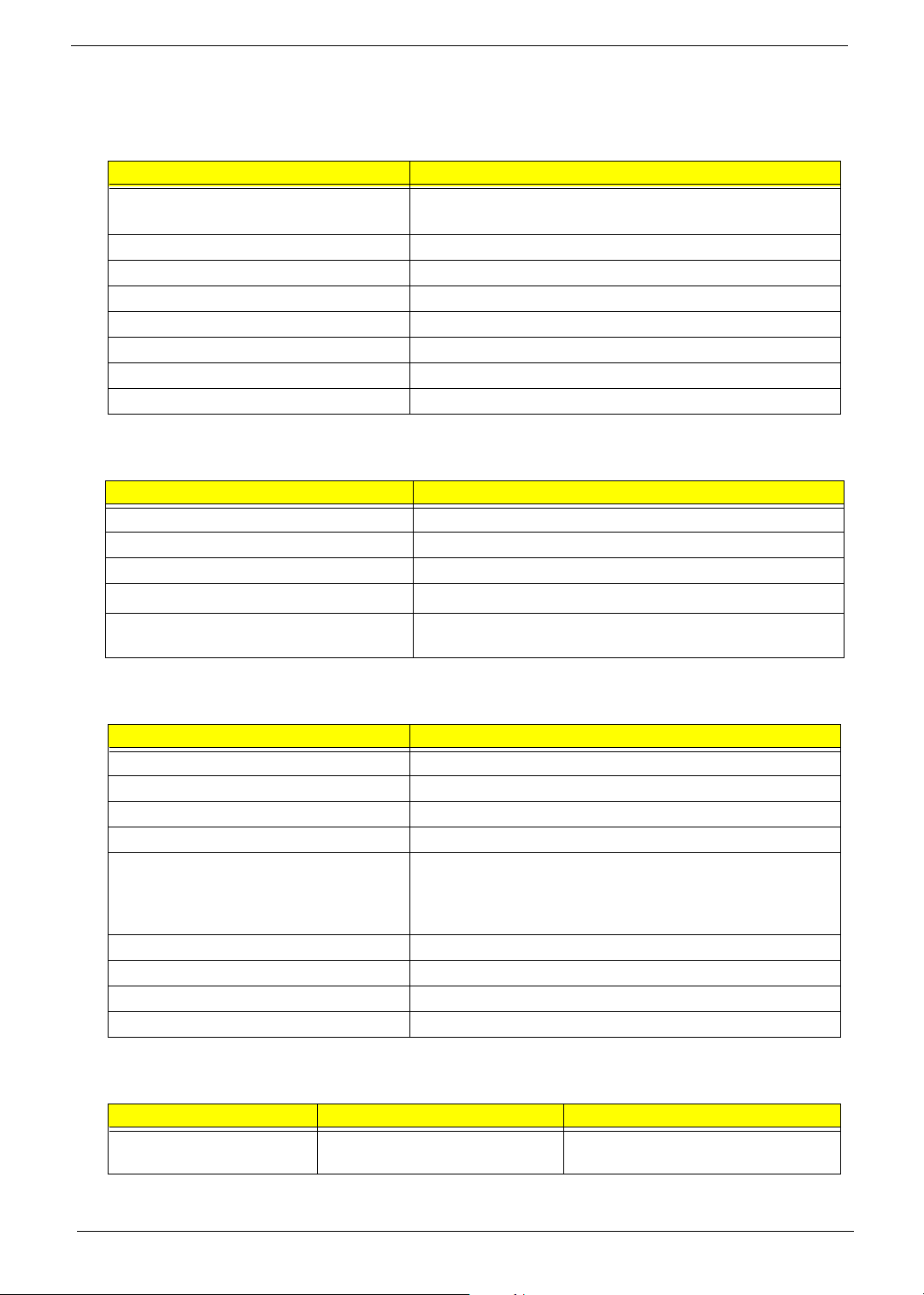
Revision History
Please refer to the table below for the updates made on Aspire T160/E360 and AcerPower M6 service guide.
Date Chapter Updates
III
Page 4

Copyright
Copyright © 2005 by Acer Incorporated. All rights reserved. No part of this publication may be reproduced,
transmitted, transcribed, stored in a retrieval system, or translated into any language or computer language, in
any form or by any means, electronic, mechanical, magnetic, optical, chemical, manual or otherwise, without
the prior written permission of Acer Incorporated.
Disclaimer
The information in this guide is subject to change without notice.
Acer Incorporated makes no representations or warranties, either expressed or implied, with respect to the
contents hereof and specifically disclaims any warranties of merchantability or fitness for any particular
purpose. Any Acer Incorporated software described in this manual is sold or licensed "as is". Should the
programs prove defective following their purchase, the buyer (and not Acer Incorporated, its distributor, or its
dealer) assumes the entire cost of all necessary servicing, repair, and any incidental or consequential
damages resulting from any defect in the software.
IV
Page 5

Acer is a registered trademark of Acer Corporation.
Intel is a registered trademark of Intel Corporation.
Athlon 64 / Athlon 64x2 / Sempron are trademarks of AMD Corporation.
Other brand and product names are trademarks and/or registered trademarks of their respective holders.
V
Page 6

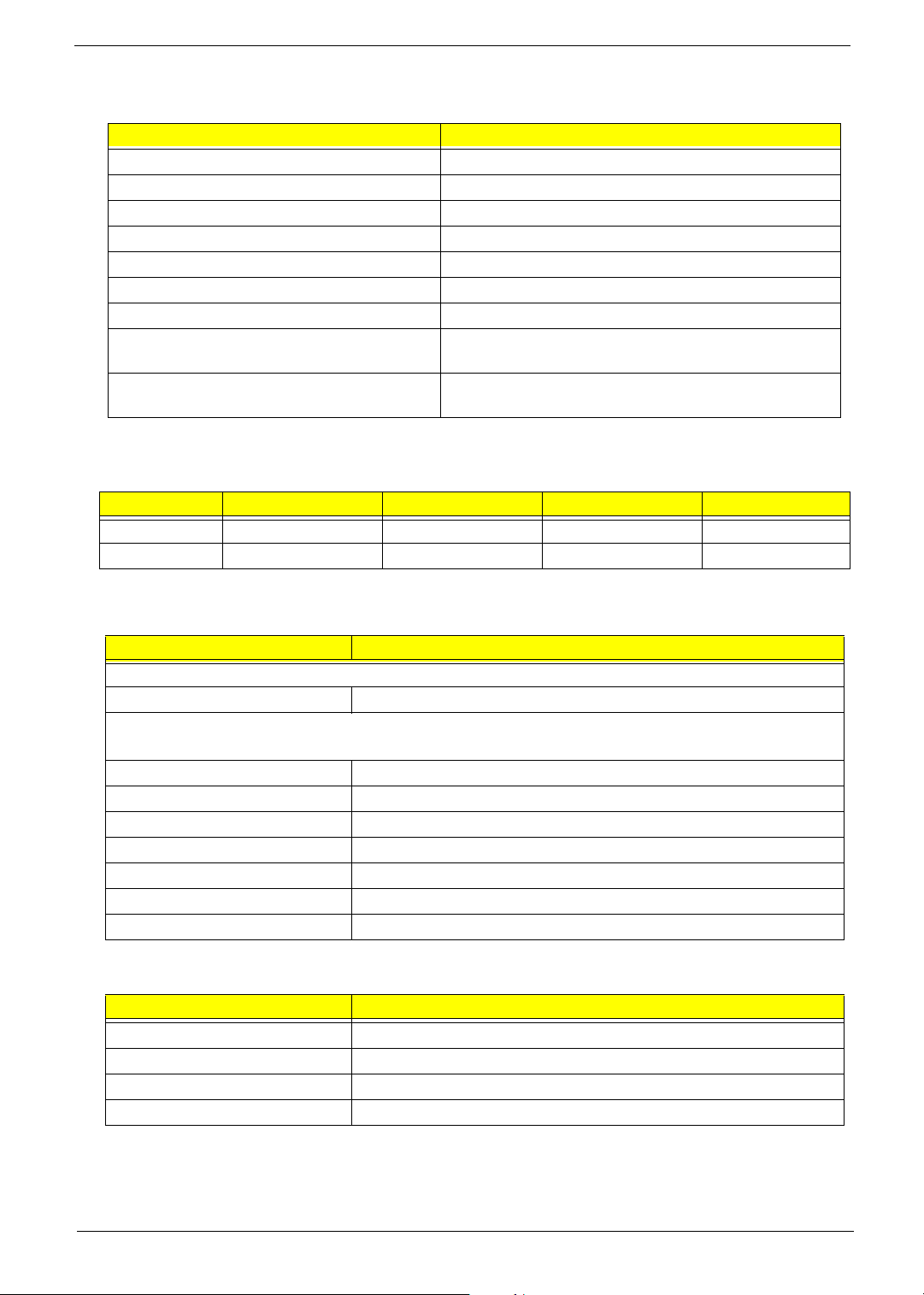
Conventions
The following conventions are used in this manual:
Screen messages Denotes actual messages that appear
on screen.
NOTE Gives bits and pieces of additional
information related to the current
topic.
WARNING Alerts you to any damage that might
result from doing or not doing specific
actions.
CAUTION Gives precautionary measures to
avoid possible hardware or software
problems.
IMPORTANT Reminds you to do specific actions
relevant to the accomplishment of
procedures.
VI
Page 7

Preface
Before using this information and the product it supports, please read the following general information.
1. This Service Guide provides you with all technical information relating to the BASIC CONFIGURATION
decided for Acer's "global" product offering. To better fit local market requirements and enhance product
competitiveness, your regional office MAY have decided to extend the functionality of a machine (e.g.
add-on card, modem, or extra memory capability). These LOCALIZED FEATURES will NOT be covered
in this generic service guide. In such cases, please contact your regional offices or the responsible
personnel/channel to provide you with further technical details.
2. Please note WHEN ORDERING FRU PARTS, that you should check the most up-to-date information
available on your regional web or channel. If, for whatever reason, a part number change is made, it will
not be noted in the printed Service Guide. For ACER-AUTHORIZED SERVICE PROVIDERS, your Acer
office may have a DIFFERENT part number code to those given in the FRU list of this printed Service
Guide. You MUST use the list provided by your regional Acer office to order FRU parts for repair and
service of customer machines.
VII
Page 8

Table of Contents
Chapter 1 System Specifications 1
Overview . . . . . . . . . . . . . . . . . . . . . . . . . . . . . . . . . . . . . . . . . . . . . . . . . . . .1
Main Board Specifications . . . . . . . . . . . . . . . . . . . . . . . . . . . . . . . . . . . . . . .2
Wake-up Event Specifications . . . . . . . . . . . . . . . . . . . . . . . . . . . . . . . . . . . 4
System LED Definition . . . . . . . . . . . . . . . . . . . . . . . . . . . . . . . . . . . . . . . . . 4
Block Diagram . . . . . . . . . . . . . . . . . . . . . . . . . . . . . . . . . . . . . . . . . . . . . . . . 5
Main Board Placement . . . . . . . . . . . . . . . . . . . . . . . . . . . . . . . . . . . . . . . . . 6
Aspire T160 Front Panel . . . . . . . . . . . . . . . . . . . . . . . . . . . . . . . . . . . . . . . . 9
Aspire E360 Front Panel . . . . . . . . . . . . . . . . . . . . . . . . . . . . . . . . . . . . . . . 10
AcerPower M6 Front Panel . . . . . . . . . . . . . . . . . . . . . . . . . . . . . . . . . . . . . 11
AcerPower M6 Rear Panel . . . . . . . . . . . . . . . . . . . . . . . . . . . . . . . . . . . . . 12
Aspire T160/E360 Rear Panel . . . . . . . . . . . . . . . . . . . . . . . . . . . . . . . . . . . 13
System Peripherals . . . . . . . . . . . . . . . . . . . . . . . . . . . . . . . . . . . . . . . . . . . 14
Acer eRecovery . . . . . . . . . . . . . . . . . . . . . . . . . . . . . . . . . . . . . . . . . . . . . . 15
Acer disc-to-disc Recovery . . . . . . . . . . . . . . . . . . . . . . . . . . . . . . . . . . . . . 17
Hardware Specifications and Configurations . . . . . . . . . . . . . . . . . . . . . . . . 18
Power Management Function (ACPI Support Function) . . . . . . . . . . . . . . . 25
Chapter 2 System Utilities
Entering Setup . . . . . . . . . . . . . . . . . . . . . . . . . . . . . . . . . . . . . . . . . . . . . . . 27
Product Information . . . . . . . . . . . . . . . . . . . . . . . . . . . . . . . . . . . . . . . . . . . 28
Standard CMOS Features . . . . . . . . . . . . . . . . . . . . . . . . . . . . . . . . . . . . . . 29
Advanced BIOS Features . . . . . . . . . . . . . . . . . . . . . . . . . . . . . . . . . . . . . . 31
Advanced Chipset Features . . . . . . . . . . . . . . . . . . . . . . . . . . . . . . . . . . . . 33
Integrated Peripherals . . . . . . . . . . . . . . . . . . . . . . . . . . . . . . . . . . . . . . . . .35
IDE Function Setup . . . . . . . . . . . . . . . . . . . . . . . . . . . . . . . . . . . . . . . . . . . 36
Onboard Device Setup . . . . . . . . . . . . . . . . . . . . . . . . . . . . . . . . . . . . . . . . 38
Onboard I/O Chip Setup . . . . . . . . . . . . . . . . . . . . . . . . . . . . . . . . . . . . . . . 39
Power Management Setup . . . . . . . . . . . . . . . . . . . . . . . . . . . . . . . . . . . . . 41
PnP/PCI configuration . . . . . . . . . . . . . . . . . . . . . . . . . . . . . . . . . . . . . . . . . 43
PC Health Status . . . . . . . . . . . . . . . . . . . . . . . . . . . . . . . . . . . . . . . . . . . . . 45
Load Default Settings . . . . . . . . . . . . . . . . . . . . . . . . . . . . . . . . . . . . . . . . . 46
Set supervisor/User Password . . . . . . . . . . . . . . . . . . . . . . . . . . . . . . . . . . 47
Save & Exit Setup . . . . . . . . . . . . . . . . . . . . . . . . . . . . . . . . . . . . . . . . . . . . 48
Exit without Saving . . . . . . . . . . . . . . . . . . . . . . . . . . . . . . . . . . . . . . . . . . . 49
Chapter 3 Machine Disassembly and Replacement
General Information . . . . . . . . . . . . . . . . . . . . . . . . . . . . . . . . . . . . . . . . . .51
Before You Begin . . . . . . . . . . . . . . . . . . . . . . . . . . . . . . . . . . . . . . . . . . . .51
Aspire T160 and AcerPower M6 Disassembly Procedure. . . . . . . . . . . . . .52
Open the Computer . . . . . . . . . . . . . . . . . . . . . . . . . . . . . . . . . . . . . . . . . . . 52
Disconnect the Cables. . . . . . . . . . . . . . . . . . . . . . . . . . . . . . . . . . . . . . . . . 52
Detach the HDD, FDD, and Card Reader (if equipped) . . . . . . . . . . . . . . . 55
Detach the USB Module . . . . . . . . . . . . . . . . . . . . . . . . . . . . . . . . . . . . . . .57
Detach the CPU Cooler . . . . . . . . . . . . . . . . . . . . . . . . . . . . . . . . . . . . . . . . 57
Remove the Memory . . . . . . . . . . . . . . . . . . . . . . . . . . . . . . . . . . . . . . . . . .58
Remove the System Fan . . . . . . . . . . . . . . . . . . . . . . . . . . . . . . . . . . . . . . .58
Remove the Main Board . . . . . . . . . . . . . . . . . . . . . . . . . . . . . . . . . . . . . . .58
Remove the Power Supply . . . . . . . . . . . . . . . . . . . . . . . . . . . . . . . . . . . . .59
Remove the CPU. . . . . . . . . . . . . . . . . . . . . . . . . . . . . . . . . . . . . . . . . . . . . 59
Aspire E360 Desassembly Procedure. . . . . . . . . . . . . . . . . . . . . . . . . . . . .59
Open the Computer . . . . . . . . . . . . . . . . . . . . . . . . . . . . . . . . . . . . . . . . . . . 60
26
50
VIII
Page 9

Table of Contents
Remove the PCI . . . . . . . . . . . . . . . . . . . . . . . . . . . . . . . . . . . . . . . . . . . . .60
Detach the CPU Cooler . . . . . . . . . . . . . . . . . . . . . . . . . . . . . . . . . . . . . . . . 61
Remove the Memory . . . . . . . . . . . . . . . . . . . . . . . . . . . . . . . . . . . . . . . . . .62
Disconnect the Cables. . . . . . . . . . . . . . . . . . . . . . . . . . . . . . . . . . . . . . . . . 62
Disassemble the HDD, ODD, FDD and Card Reader . . . . . . . . . . . . . . . . .65
Disassemble the USB Module. . . . . . . . . . . . . . . . . . . . . . . . . . . . . . . . . . .67
Remove the System Fan . . . . . . . . . . . . . . . . . . . . . . . . . . . . . . . . . . . . . . .67
Remove the Main Board . . . . . . . . . . . . . . . . . . . . . . . . . . . . . . . . . . . . . . .67
Remove the Power Supply . . . . . . . . . . . . . . . . . . . . . . . . . . . . . . . . . . . . .68
Separate the CPU from the Main Board . . . . . . . . . . . . . . . . . . . . . . . . . . . 68
Chapter 4 Troubleshooting 6
Power-On Self-Test (POST) . . . . . . . . . . . . . . . . . . . . . . . . . . . . . . . . . . . . 69
POST Error Messages List . . . . . . . . . . . . . . . . . . . . . . . . . . . . . . . . . . . . . 76
Error Symptoms List . . . . . . . . . . . . . . . . . . . . . . . . . . . . . . . . . . . . . . . . . .78
Undetermined Problems . . . . . . . . . . . . . . . . . . . . . . . . . . . . . . . . . . . . . . .83
Chapter 5 Jumper and Connector Information
Connectors Introduction . . . . . . . . . . . . . . . . . . . . . . . . . . . . . . . . . . . . . . . 84
ATX_12V/ATX (Power Connector) . . . . . . . . . . . . . . . . . . . . . . . . . . . . . . . 85
CPU Fan/System Fan (Cooler Fan Power Conncetor). . . . . . . . . . . . . . . . 87
FDD (Floppy Connector) . . . . . . . . . . . . . . . . . . . . . . . . . . . . . . . . . . . . . . 88
IDE1/IDE2 (IDE Connector) . . . . . . . . . . . . . . . . . . . . . . . . . . . . . . . . . . . . 89
SATA1/SATA2/SATA3/SATA4 (Serial ATA Connector) . . . . . . . . . . . . . . . 91
F_Panel (Front Panel Jumper) . . . . . . . . . . . . . . . . . . . . . . . . . . . . . . . . . . 92
F_Audio (Front Audio Panel connector) . . . . . . . . . . . . . . . . . . . . . . . . . . . 93
CD_IN (CD In Connector, Black) . . . . . . . . . . . . . . . . . . . . . . . . . . . . . . . . 94
F_USB1/F_USB2/F_USB3 (Front USB Connector) . . . . . . . . . . . . . . . . . . 94
F_1394 (IEEE 1394 Connector) . . . . . . . . . . . . . . . . . . . . . . . . . . . . . . . . . 95
SPDIF_OUT (SPDIF Out). . . . . . . . . . . . . . . . . . . . . . . . . . . . . . . . . . . . . . 96
CLR_CMOS (Clear CMOS) . . . . . . . . . . . . . . . . . . . . . . . . . . . . . . . . . . . . 97
INTR (Intruder, Case Open Header). . . . . . . . . . . . . . . . . . . . . . . . . . . . . . 97
BAT (Battery) . . . . . . . . . . . . . . . . . . . . . . . . . . . . . . . . . . . . . . . . . . . . . . . 98
How to Erase CMOS . . . . . . . . . . . . . . . . . . . . . . . . . . . . . . . . . . . . . . . . . 98
9
84
Chapter 6 FRU (Field Replaceable Unit) List 99
General Description . . . . . . . . . . . . . . . . . . . . . . . . . . . . . . . . . . . . . . . . . . 99
Aspire E360 Exploded Diagram . . . . . . . . . . . . . . . . . . . . . . . . . . . . . . . . 100
AcerPower M6 Exploded Diagram . . . . . . . . . . . . . . . . . . . . . . . . . . . . . . 101
Parts . . . . . . . . . . . . . . . . . . . . . . . . . . . . . . . . . . . . . . . . . . . . . . . . . . . . . 102
IX
Page 10

System Specifications
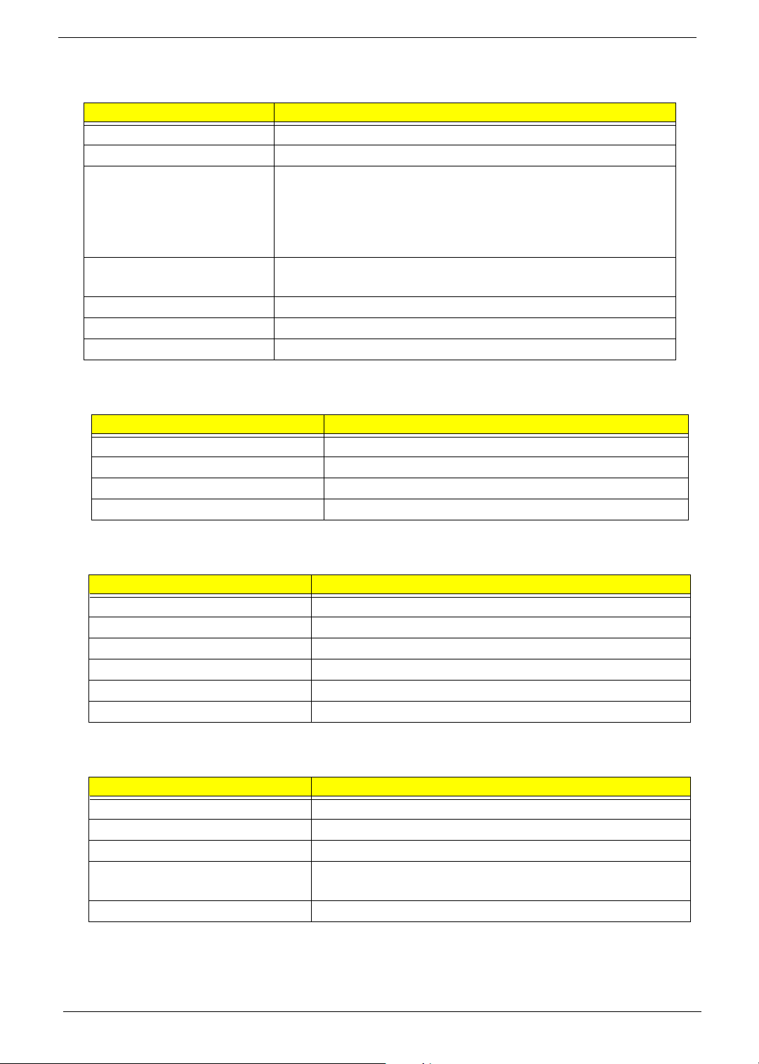
Overview
CPU AMD Athlon 64 / Athlon 64x2 / Sempron (939)
Chipset C51G + MCP51
Memory Dual Channel DDR1 266/333/400, four DDR1 DIMM (Max. four GB)
supported
System BIOS Feature LCP-4MB (wake on LAN boot)
Award BIOS code
ACPI supported; S3 will be defaulted.
Hardware monitor supported
Super I/O ITE8712F with hardware monitor
IDE Interface PCI bus master enhanced IDE (MCP51)
RTC NCP51
Chapter 1
Serial ATA Independent DMA operation on four ports
Data transfer rates up to 300MB/sec.
SATA II Support Raid function
FDD Interface
Audio Audio on board (ALC850, 7.1 channels)
LAN Marvell 88E1111
USB USB 2.0 host controller supporting up to eight ports
Expansion Slots Three PCI slot (PCI 2.3), one PCI Express x16 graphics slot
I/O Ports One serial port, one parallel (EPP/ECP supported), eight USB ports
Power Connectors 24-pin ATX power connector and ATX 12V connector
Power management Dark green, ACPI 2.0 compliant, SMBIOS 2.3
1.44/2.88MB FDD
(four rear panel / four front panel), VGA port, RJ45, one PS/2 keyboard
port and one PS/2 mouse port, audio jack six mic-in, line-in, and lineout
Chapter 1 1
Page 11

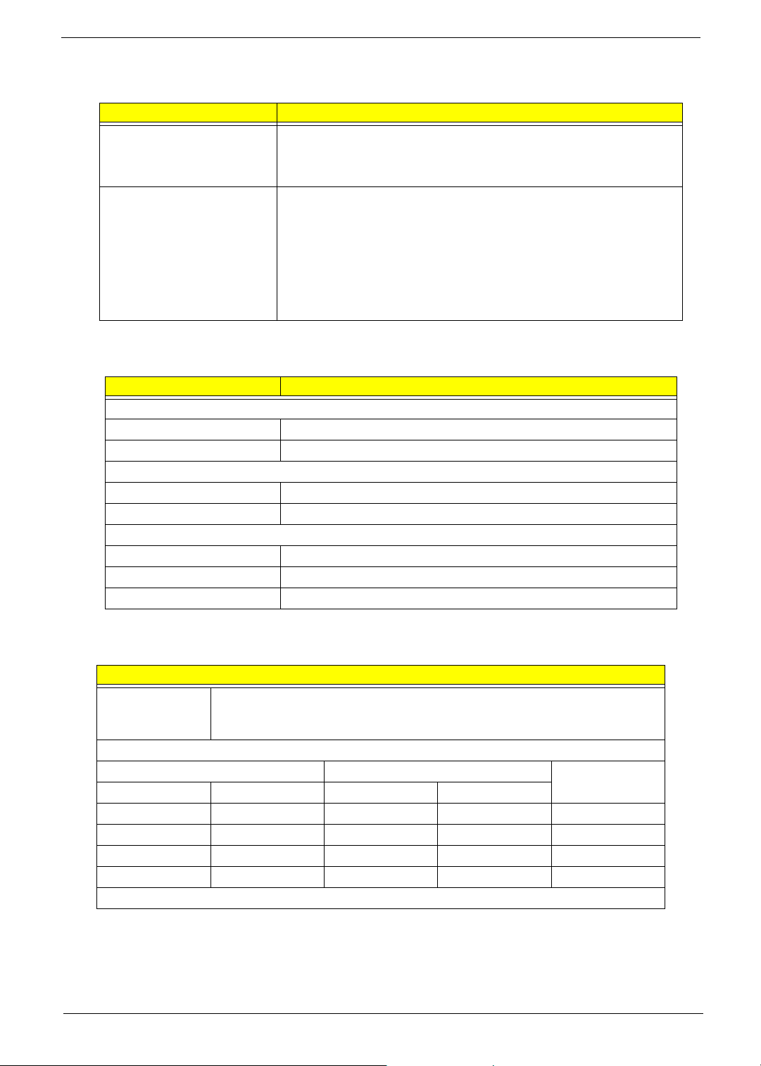
Main Board Specifications
Description
Size
Processor
System Chipset
Memory
PCI Express / PCI Slots
FDD Interface
IDE Interface
T Max. 244 mm x 244 mm, Micro ATX
T Processor type: AMD Athlon 64 / Athlon 64x2 / Sempron
T Socket type: AMD Socket 939
T Socket quantity: one
T North bridge: Nvidia C51G
T South bridge: MCP51
T Memory type:
T DDR
T CAS latency, CL = 4
T Socket type: DDR memory slots
T Socket quantity: four
T Capacity: 256MB to 4GB
T Single channel
T PCI Express Slot type: x1 / x16
T Quantity: none / one
T PCI Slot type: PCI 2.3 5V slots
T Quantity: two
T Slot quantity: one
T One 1.44MB 3.5” device
T Slot type: 40 pin PATA IDE slot
T Quantity: two
T Transfer rate support: PIO Mode (0/1/2/3/4), ATA
Mode (33/66/100/133)
T Device type support: HDD / CD-ROW / CD-RW / DVD-
ROM / Combo / DVD burner
T Connector type: SATA IDE connector
T Quantity: four
T Storage type support: HDD
Audio
T Controller: MCP51
T Codec: Realtek ALC850 (7.1 channel audio support)
T UAJ support (HD audio feature suppport on rear only)
T Reserved disable function on BIOS side. Default is
enabled.
LAN T Controller: MCP51
T LAN chip: Marvell 88E1111
T 10/100/1000 BASE-T IEEE 802.3 compliant
USB (AcerPower M6)
T Controller: MCP51
T Connector quantity: eight
T Rear connectors: four
T On-board header: two (2*5 pin)
T Two for front daughter board (2*5 pin Intel FPIO)
T Data transfer rate support: USB 2.0/1.1
2 Chapter 1
Page 12

Description
USB (Aspire E360/T160) T Controller: MCP51
T Connectors Quantity: eight
T Rear connectors: four
T On-board header: three (2*5 pin)
T One for front daughter board (2*5 pin Intel EPIO)
T One for Multi Card Reader (2*5 pin)
T One for cable (leverage rear USB ports)
T Data transfer rate support: USB 2.0/1.1
I/O Ports
All On-Board Connector /
Device List
T Dual stack PS/2 keyboard / mouse
T Parallel port
T Serial port
T VGA port
T Dual stack USB ports with 1394
T Dual stack USB ports with RJ45 connector
T Vertical audio connector with line-in, line-out and
microphone
T Rear I/O connectors
T One PS/2 keyboard port, one PS/2 mouse port
T One parallel port, one serial port
T One VGA (CRT) port
T One GigaLAN port
T Four USB ports (AcerPower M6) / Two USB ports
(Aspire T160/E360)
T Six ports jack supporting HD audio output
T On-board connectors / devices
T One CPU socket
T Four memory sockets
T One PCI Express x16 slot
T One PCI Express x1 slot
T Two PCI slots
T One FDD slot
T Tw o PATA I D E s lot
T Four PATA IDE connectors
T Two 2*5 pin Intel FPIO specification USB pin
connectors
T One 2*5 pin USB pin connector
T One 2*5 Intel FPIO specification front audio connector
T One serial port pin connector
T One CD-In four-pin connector (CD-ROM / TV tuner
card audio input)
T One four-pin CPU fan connector
T Two three-pin system fan connectors
T One 20-pin + four-pin ATX interface PS3/PS2 SPS
connector
T One 2*7 Power / LED FPIO (following Intel FPIO
spec.)
T One buzzer
Chapter 1 3
Page 13
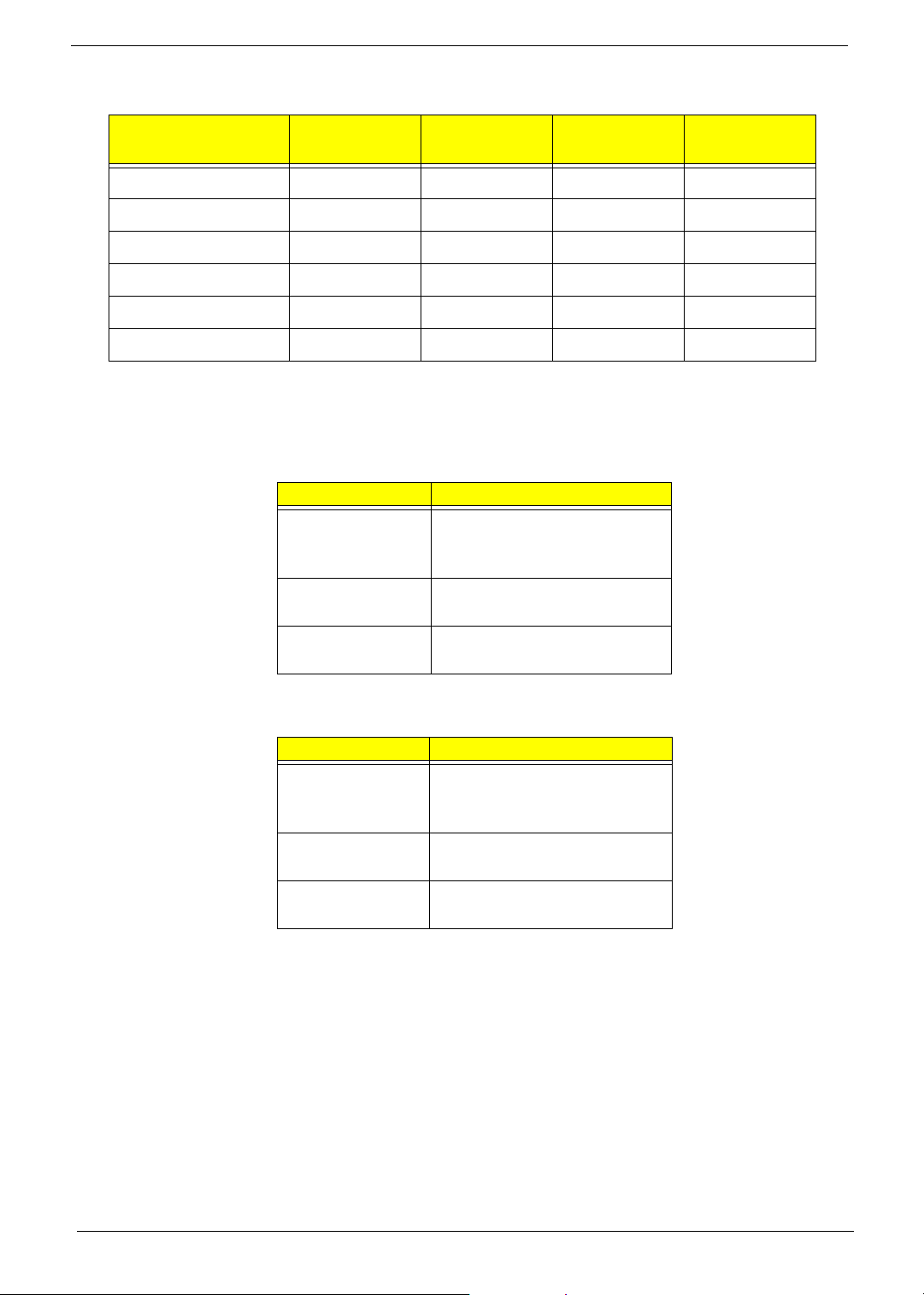
Wake-up Event Specifications
Device S1 (Idle)
Power button Enabled Enabled Enabled Enabled
PS/2 keyboard Enabled Enabled Enabled No
USB keyboard Enabled Enabled Disabled No
RTC Disabled Disabled Disabled Disabled
Lan Disabled Disabled Disabled Disabled
Modem (Ring) Disabled Disabled Disabled Disabled
S3 (Suspend
to RAM)
S4 (Suspend
to Disk)
System LED Definition
Aspire T160
State Response
Power state LED S0: Green steady
S1/S3: Green blinking
S4/S5: Off
HDD state LED IDE active: Red blinking
IDE idle: Off
LAN state LED LAN active: Green blinking
LAN idle: Off
S5 (Shut
down)
Aspire E360 / AcerPower M6
State Response
Power state LED S0: Blue steady
S1/S3: Blue blinking
S4/S5: Off
HDD state LED IDE active: Blue blinking
IDE idle: Off
LAN state LED LAN active: Blue blinking
LAN idle: Off
4 Chapter 1
Page 14
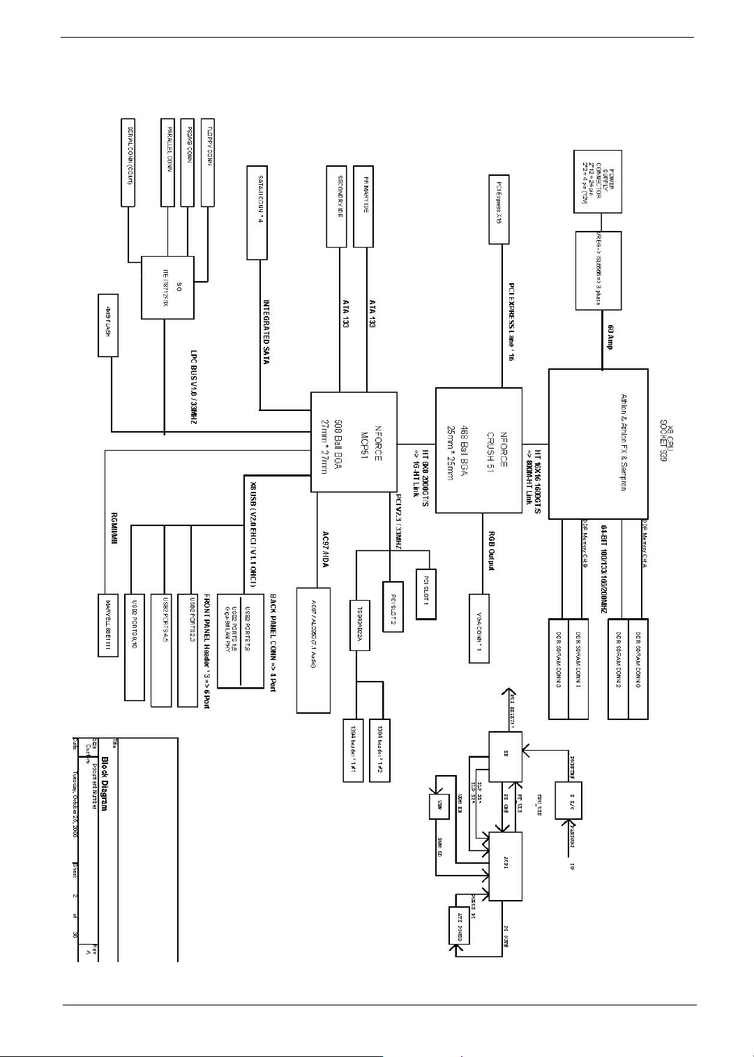
Block Diagram
Chapter 1 5
Page 15
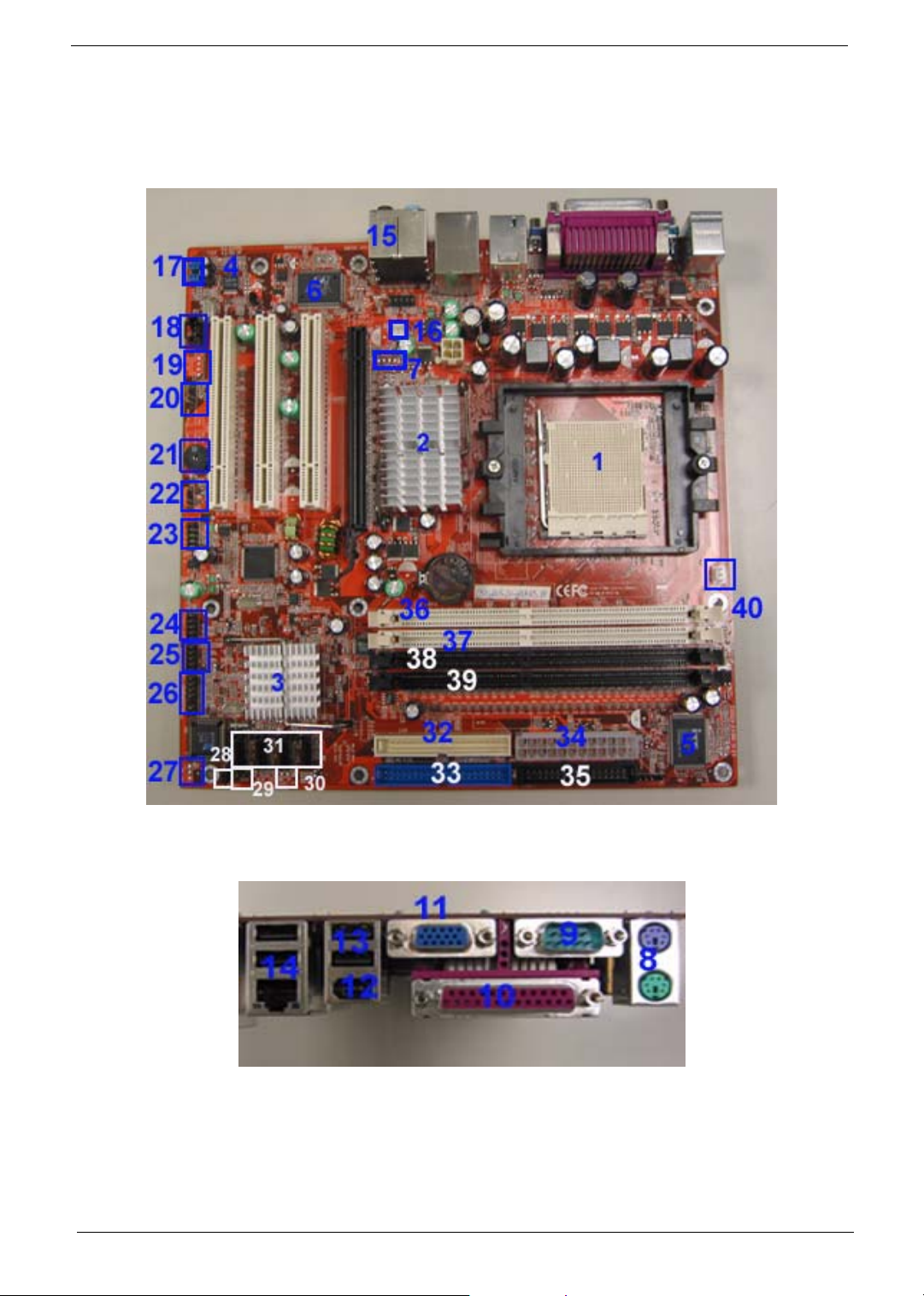
Main Board Placement
6 Chapter 1
Page 16

No. Label Description
1U16 CPU socket
2 U15 North bridge
3 U26 South bridge
4 U2 Audio codec
5 U29 Super I/O controller
6 U3 LAN controller
7J4 TV OUT port
8 KB / MS Keyboard and mouse
9 COM1 COM1
10 PRT Printer
11 V GA VGA
12 1394_USB 1394 USB
13 USB USB port
14 NIC_USB Network and USB connector
15 Audio Audio
16 SYS_FAN System fan connector
17 F_Audio Front audio header
18 CD_IN CD IN
19 AUX_IN AUX IN
20 SPDIF_OUT SPDIF_OUT
21 BZ1 Buzzer
22 SPEAKER Speaker cable connector
23 F_1394 Front 1394 header
24 F_USB1 Front USB header
25 F_USB2 Front USB header
26 FP Front panel
27 TBL_EN Boot block jumper
28 CLR_CMOS Clear CMOS (password switch)
29 INTR Intruder
30 J2 Recovery
Chapter 1 7
Page 17

No. Label Description
31
(from left
to right)
32 SIDE Secondary IDE port
33 PIDE Primary IDE port
34 Floppy Floppy drive connector
35 PWR1 24-pin power connector
36 DIMM1 DIMM socket 1
37 DIMM2 DIMM socket 2
38 DIMM3 DIMM socket 3
39 DIMM4 DIMM socket 4
40 CPU_FAN CPU fan connector
SATA_1 SATA_1
SATA_2 SATA_2
SATA_3 SATA_3
SATA_4 SATA_4
8 Chapter 1
Page 18
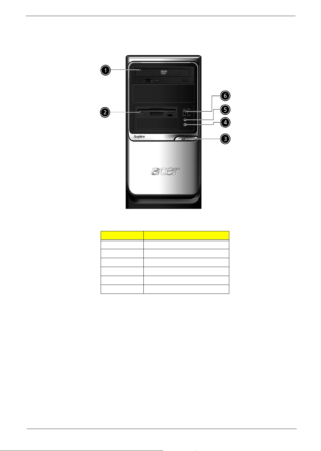
Aspire T160 Front Panel
No. Description
1 Optical device
2 Floppy drive
3 Power button
4 Microphone jack
5 Speaker/Headphone jack
6 USB ports
Chapter 1 9
Page 19
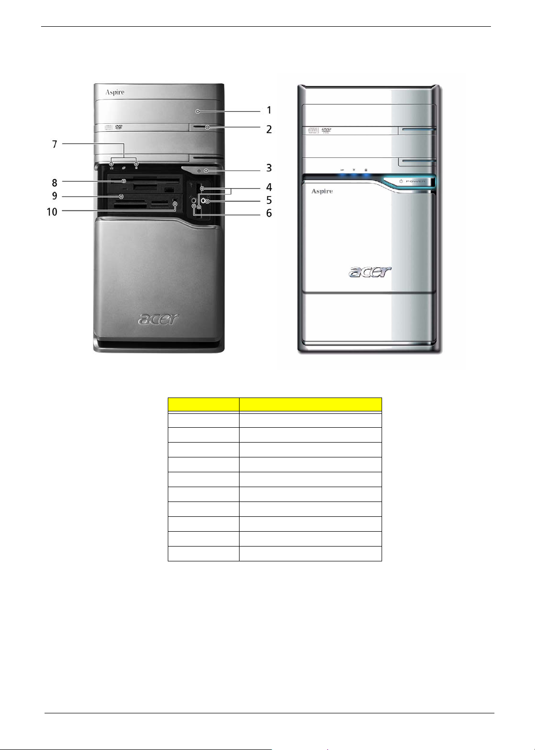
Aspire E360 Front Panel
No. Description
1 Optical driver
2 Optical drive eject button
3 Power button
4 USB ports
5 Speaker/Headphone jack
6 Microphone jack
7 Indicators
8 Floppy disk drive
9 Card reader
10 IEEE 1394 port
NOTE: The picture left is the front bezel with cover slided down.
10 Chapter 1
Page 20
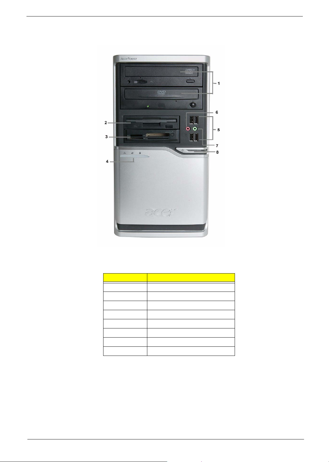
AcerPower M6 Front Panel
No. Description
1 Optical drive
2 Floppy disk drive
3 Card reader
4 Indicators
5 USB ports
6 Microphone jack
7 Speaker/Headphone jack
8 Power button
Chapter 1 11
Page 21

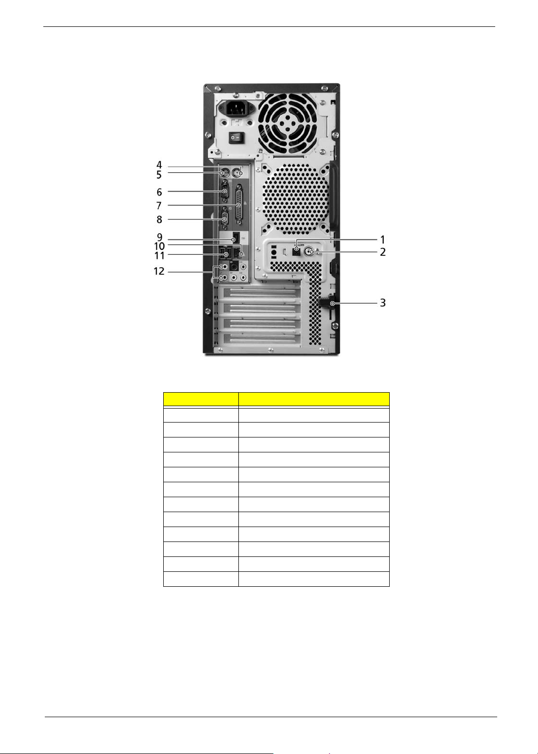
AcerPower M6 Rear Panel
No. Description
1 Power supply
2 Power cord socket
3 Voltage select switch
4 PS/2 Mouse port
5 PS/2 Keyboard port
6 Serial port
7 Printer port
8VGA port
9 USB Ports
10 RJ45 port
11 Audio jacks
12 Expansion slots
13 Lock handle
14 SPDIF port
15 Recovery switch holder
12 Chapter 1
Page 22
Aspire T160/E360 Rear Panel
No. Description
1 SPDIF port
2 SPDIF port
3 Lock handle
4 PS/2 Mouse port
5 PS/2 Keyboard port
6 Serial port
7 Printer port
8VGA port
9 IEEE 1394 port
10 LAN port
11 USB ports
12 Audio jacks
Chapter 1 13
Page 23
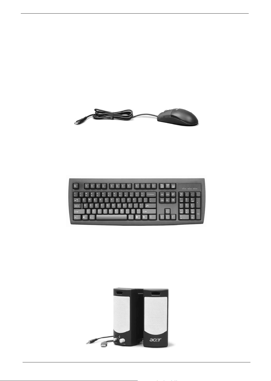
System Peripherals
Note:
The Aspire T160/E360 and AcerPower M6 computer consist of the system itself, and system peripherals, like
a mouse, keyboard and a set of speakers (optional). This section provides a brief description of the basic
system peripherals.
Mouse (PS/2 or USB, manufacturing option)
The included mouse is a standard two-button wheel mouse. Connect the mouse to the PS/2 mouse port or
USB port on the back panel of the system.
Keyboard (PS/2 or USB, manufacturing option)
Connect the keyboard to the PS/2 keyboard port or USB port on the back panel of the system.
Speakers
For system bundled with speakers, before powering on the system, connect the speaker cable to the audio out
(external speaker) port on the back panel of the system. Please refer to the included operating instructions for
more information.
NOTE: speakers are optional and the appearance might be different depending on the actual product.
14 Chapter 1
Page 24

Acer eRecovery
Acer eRecovery is a tool to quickly backup and restore the system. Users can create and save a
backup of the current system configuration to hard drive, CD, or DVD.
Acer eRecovery consists of the following functions:
1. Create backup
2. Restore from backup
3. Create factory default image CD
4. Re-install bundled software without CD
5. Change Acer eRecovery password
Create Backup
Users can create and save backup images to hard drive, CD, or DVD.
1. Boot to Windows XP
2. Press <Alt>+<F10> to open the Acer eRecovery utility.
3. Enter the password to proceed. The default password is six zeros.
4. In the Acer eRecovery window, select Recovery settings and click Next
5. In the Recovery settings window, select Backup snapshot image and click Next.
6. Select the backup method.
T Use Backup to HDD to store the backup disc image on drive D:.
T Backup to optical device to store the backup disc image on CD or DVD (only available on
systems that include an optical disc burner).
7. After choosing the backup method, click Next.
Follow the instruction on screen to complete the process.
Restore from backup
Users can restore backup previously created (as stated in the Create backup section) from hard drive,
CD, or DVD.
1. Boot to Windows XP.
2. Press <Alt>+<F10> to open the Acer eRecovery utility.
3. Enter the password to proceed. The default password is six zeros.
4. In the Acer eRecovery window, select Recovery actions and click Next.
5. Select the desired restore action and follow the onscreen instructions to complete the restore process.
Create factory default image CD
When the System CD and Recovery CD are not available, you can create them by using this feature.
1. Boot to Windows XP.
2. Press <Alt>+<F10> to open the Acer eRecovery utility.
Chapter 1 15
Page 25

3. Enter the password to proceed. The default password is six zeros.
4. In the Acer eRecovery window, select Recovery settings and click Next.
5. In the Recovery settings window, select Burn image to disc and click Next.
6. In the Burn image to disc window, select 01. Factory default image and click Next.
7. Follow the instructions on screen to complete the process.
Re-install bundled software without CD
Acer eRecovery stores pre-loaded software internally for easy driver and application re-installation.
1. Boot to Windows XP.
2. Press <Alt>+<F10> to open the Acer eRecovery utility.
3. Enter the password to proceed. The default password is six zeros.
4. In the Acer eRecovery window, select Recovery actions and click Next.
5. In the Recovery settings window, select Reinstall applications/drivers and click Next.
6. Select the desired driver/application and follow the instructions on screen to re-install.
At first launch, Acer eRecovery prepares all the needed software and may take few seconds to bring up the
software content window.
Change Password
Acer eRecovery and Acer disc-to-disc recovery are protected by a password that can be changed by
the user. Follow the steps below to change the password in Acer eRecovery.
1. Boot to Windows XP.
2. Press <Alt>+<F10> to open the Acer eRecovery utility.
3. Enter the password to proceed. The default password is six zeros.
4. In the Acer eRecovery window, select Recovery settings and click Next.
5. In the Recovery settings window, select Password: Change Acer eRecovery password and click Next.
6. Follow the instructions on screen to complete the process.
16 Chapter 1
Page 26

Acer disc-to-disc recovery
Restore without a Recovery CD
This recovery process helps you restore the C: drive with the original software content that is installed when
you purchase your PC. Follow the steps below to rebuild your C: drive. (Your C: drive will be
reformatted and all data will be erased.) It is important to back up all data files before you use this option.
1. Restart the system.
2. While the Acer logo is showing, press <Alt>+<F10> at the same time to enter the recovery process.
3. The message "The system has password protection. Please enter 000000:" is displayed.
4. Enter six zeros and continue.
5. The Acer Recovery main page appears.
6. Use the arrow keys to scroll through the items (operating system versions) and press <Enter> to select.
Multilingual operating system installation
Follow the instructions to choose the operating system and language you prefer when you first power-on the
system.
1. Turn on the system.
2. Acer's multilingual operating system selection menu will pop-up automatically.
3. Use the arrow keys to scroll to the language version you want. Press <Enter> to confirm your selection.
4. The operating system and language you choose now will be the only option for future recovery
operations.
5. The system will install the operating system and language you choose.
Chapter 1 17
Page 27
Hardware Specifications and Configurations
Major Chips
Item Specification
System Core Logic Nvidia C51G
MCP51
Super I/O Controller ITE 8712F
LAN Controller Marvell 88E1111
Memory Controller Nvidia C51G
IDE Controller MCP51
Audio Controller ALC850
VGA Controller Nvidia C51G
Keyboard Controller ITE 8712F
Processor
Item Specification
Type AMD Athlon 64 / Athlon 64x2 / Sempron
Slot Socket 939
Speed Depends on CPU, which is local configured
Bus Frequency
Voltage Processor voltage can be detected by any system without
HyperTransport
setting any jumper
TM
technology up to 1.0 GHz
BIOS
Item Specification
BIOS code programmer Phoenix Award
BIOS version R01-B1
BIOS ROM size 4MB
BIOS ROM package 32-pin PLCC package
Support protocol PCIX 1.0,PCI 2.2,APM 1.2,VESA/DPMS (VBE/PM V1.1),
SMBIOS 2.3, E-IDE 1.1, ACPI 1.0b,ESCD1.03, PnP 1.0a,
Bootable CD-ROM 1.0, USB 1.1~ USB 2.0, UHCI 1.0, ANSI
ATA 3.0 ATAPI
Boot from CD-ROM feature Yes
Support to LS-120 drive Yes
Support to BIOS boot block feature Yes
BIOS Password Control Yes
BIOS Hotkey
Hotkey Function Description
DEL Enter BIOS Setup Utility Press while the system is booting to
enter BIOS Setup Utility.
18 Chapter 1
Page 28
System Memory
Item Specification
Memory Slot Number four slots
Memory Size per Slot 256 MB ~ 1GB
Supported Maximum Memory Size 4GB
Supported Memory Speed 400 MHz
Supported memory voltage 1.8 V
Support memory module package 240-pin DIMM
Support to parity check feature Yes
Support to Error Correction Code (ECC)
feature
Memory module combinations You can install memory modules in any combination as
VRM (Voltage Regulator Module)
Function VRM Specification Typical Voltage Power Source Maximum Output
CPU VRM VRM10.1 0.8375~1.6v 12 Voltage 101A
CPU VRM VRM 9.0 1.1-1.85 Voltage 12 Voltage 70A
Yes
long as they match the above specifications.
Cache Memory
Item Specification
First-Level Cache Configurations
Cache function control Enable/Disable by BIOS Setup
Second-Level Cache Configurations
The information below is only applicable to system installed with a Pentium 4 processor
Tag RAM Location On Processor
L2 Cache RAM Location On Processor
L2 Cache RAM type PBSRAM (Pipelined-burst Synchronous RAM)
L2 Cache RAM size Depends on CPU, which is local configured
L2 Cache RAM speed Full of the processor core clock frequency (Advanced Transfer Cache)
L2 Cache function control Enable/Disable by BIOS Setup
L2 Cache scheme Fixed in write-back
LAN Interface
Item Specification
LAN Controller
LAN Controller Resident Bus PCI Bus
LAN Port One RJ45 on board
Function Control Enable/Disable by BIOS Setup
Marvell 88E1111 GigaLAN Controller
Chapter 1 19
Page 29
IDE Interface
Item Specification
IDE Controller MCP51
IDE Controller Resident Bus ATA133
Number of 40-pin PATA slot Two
Device Type Support: HDD, CD-ROM, CD-RW, DVD-ROM, Combo,
DVD burner
Transfer Rate Support: PIO 0/1/2/3/4
ATA Mode: 33/66/100/133
Number of STAT IDE slot Four
Device Type Support: HDD
LS-120 Supported
Bootable CD-ROM Supported
Function Control Enable/Disable by BIOS setup
Diskette Drive Interface
Item Specification
Diskette Drive Controller ITE 8712F
Diskette Drive Controller Resident Bus LPC Bus V1.0 / 33MHz
Supported Diskette Drive Formats 1.44MB, 2.88MB format and slim type diskette drive
Function Control Enable/Disable by BIOS Setup
Serial Port
Item Specification
Serial port controller ITE 8712F
Serial port controller resident bus LPC Bus V1.0 / 33MHz
Number of serial port One
Serial port location Rear Panel
16550 UART support Yes
Connector type 9-pin D-type female connector
USB Port
Item Specification
Universal HCI USB 2.0/1.1
Controller MCP51
Number of the connectors eight
Location Rear: four for AcerPower M6; two for Aspire T160/E360
Front: four for AcerPower M6; two for Aspire T160/E360
USB Class with support for legacy input devices
20 Chapter 1
Page 30
Special Design Specifications
Thermal T Dynamic fan speed control by hardware monitor
T CPU over temperature (over 120
o
C) power off
protection
Power On / Wake-Up Event
T Power Button: S1/S3/S4/S5
T PS/2 Keyboard: S1/S3/S4
T USB Keyboard: S1/S3/S4
T RTC: S1/S5
T LAN: S1/S3/S5
T Modem (Ring): S1/S3/S5
Environment Requirements
Temperature
Operating +5°C ~ +35°C
Non-operating -20°C ~ +60°C (packed), -10°C ~ +60°C (un-packed)
Humidity
Operating 15% to 80% RH, non-condensing
Non-operating 10% to 90% RH, non-condensing at 40°C
Vibration
Operating (unpacked) 5 ~ 500Hz, 2.20g RMS random, 10 minutes per axis in all three axes
Non-operating (packed) 5 ~ 500Hz, 1.09g RMS random, one hour per axis in all three axes
Shock Operating Half sine, 2g 11m seconds
Drop Test
Definition The protection ability of packing & cushion must be capable of withstanding,
with no physical or functional damage, mechanical impact from height-specific
drops.
Test Standard
Package Cross Weight Drop Height Times of Drop
KGs lbs CM Inch
0~9.10~20763010
9.1~18.2 20~40 61 24 10
18.2~27.3 40~60 46 18 10
27.3~45.4 60~100 31 12 10
10 drops: one corner, three edges, six surfaces
Chapter 1 21
Page 31

Input / Output Map Assignment 1
Address Device
22 Chapter 1
Page 32

Input / Output Map Assignment 2
Address Device
Chapter 1 23
Page 33

Memory Map Assignment
Address Device
24 Chapter 1
Page 34

Power Management Function (ACPI support function)
Device Standby Mode
T Independent power management timer for hard disk drive devices
(0-15 minutes, time step=1 minute).
T Hard disk drive goes into Standby mode (for ATA standard interface).
T Disable V-sync to control the VESA DPMS monitor.
T Resume method: device activated (Keyboard for DOS, keyboard & mouse for Windows).
T Resume recovery time: 3-5 sec.
Global Standby Mode
T Global power management timer (2-120 minutes, time step=10 minute).
T Hard disk drive goes into Standby mode (for ATA standard interface).
T Disable H-sync and V-sync signals to control the VESA DPMS monitor.
T Resume method: Return to original state by pushing external switch button, modem ring in,
keyboard and mouse for APM mode.
T Resume recovery time: 7-10 sec.
Suspend Mode
T Independent power management timer (2-120 minutes, time step=10 minutes) or pushing external
switch button.
T CPU goes into SMM.
T CPU asserts STPCLK# and goes into the Stop Grant State.
T LED on the panel turns amber colour.
T Hard disk drive goes into SLEEP mode (for ATA standard interface).
T Disable H-sync and V-sync signals to control the VESA DPMS monitor.
T Ultra I/O and VGA chip go into power saving mode.
T Resume method: Return to original state by pushing external switch button, modem ring in,
keyboard and mouse for APM mode.
T Return to original state by pushing external switch button, modem ring in and USB keyboard for
ACPI mode.
ACPI
T ACPI specification 1.0b.
T S0, S1, S3 and S5 sleep state support.
T On board device power management support.
T On board device configuration support.
Chapter 1 25
Page 35

Chapter 2
System Utilities
BIOS (Basic Input and Output System) includes a CMOS SETUP utility which allows users to configure
required setting or to activate certain system features.The CMOS SETUP saves the configuration in the
CMOS SRAM on the main board. When the power is off, the battery on the main board supplies the necessary
power to the CMOS SRAM.
When the power is on, pressing the <Delete> button during the BIOS POST (Power-On Self Test) will take you
to the CMOS SETUP screen. When setting up BIOS for the first time, it is recommended that you save the
current BIOS to a disk in the event that BIOS needs to be reset to its original settings.
Q-Flash allows the users to quickly and easily update or backup BIOS without entering the operating system.
BIOS is a Windows-based utility that doesn’t require users to boot to DOS before upgrading BIOS but directly
download and update BIOS from the Internet.
Item Description
wxyz
e
^ Main Menu: Quit and not save changes into CMOS Status Page Setup
{ Increase the numeric value or make changes
} Decrease the numeric value or make changes
l General help, displays a screen that describes all key functions
t Loads an default setting for stable performance
u Save all the CMOS changes, only for Main Menu
Move to selection
Select Item
Menu and Option Page Setup Menu, Exit current page and return to
Main Menu.
Chapter 2 26
Page 36

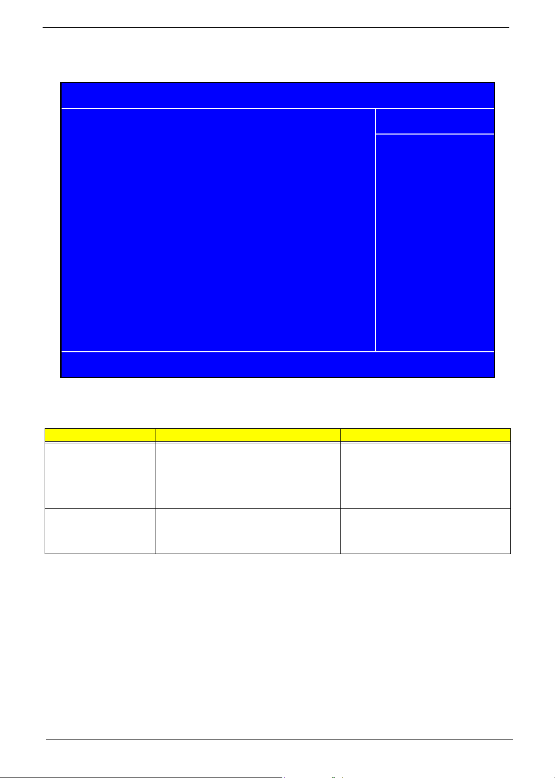
Entering Setup
Power on the computer and the system will start POST(Power On Self Test) process. When the message of
“Press DEL to enter SETUP” appears on the screen, press the key of [Delete] to enter the setup menu. Once
enter Award BIOS CMOS Setup Utility, the Main Menu (as figure below) will appear on the screen. Use arrow
keys to select among the items and press <Enter> to accept or enter the sub-menu.
Phoenix - Award BIOS CMOS Setup Utility
Product Information
Standard CMOS Features Load Optimized Defaults
Advanced BIOS Features
Advanced Chipset Features
Integrated Peripherals
Power Management Setup Exit Without Saving
PnP/PCI Configurations
Esc:Quit : Select Item
F10:Save & Exit Setup
PC Health Status
Set Supervisor Password
Set User Password
Save & Exit Setup
Parameter Description
Product Information This page shows the relevant information of the main board
Standard CMOS Features This setup page includes all the items in standard compatible BIOS
Advanced BIOS Features This setup page includes all the items of Award special enhanced
features
Advanced Chipset Features This setup page includes all advanced chipset features
Integrated Peripherals This setup page includes all onboard peripherals
Power Management Setup This setup page includes all the items of Green function features
PnP/PCI Configuration This setup page includes all configurations of PCI&PnP ISA resources
PC Health Status This setup page is the System auto detect Temperature, voltage, fan
and speed
Load Optimized Settings Default Settings indicates the value of the system parameters which
the system would be in best performance configuration
Set Supervisor Password Change, set or disable password. It allows you to limit access to the
system and Setup, or just to Setup
Set User Password Change, set or disable password. It allows you to limit access to the
system
Save & Exit Setup Save CMOS value settings to CMOS and exit setup
Exit Without Saving Abandon all CMOS value changes and exit setup
27 Chapter 2
Page 37

Product Information
Phoenix - Award BIOS CMOS Setup Utility
Product Information
Product Name AST160/ASE360/APM6
Main Board ID FC51GM
System S/N
Main Board S/N
System Manufacture Name Acer
Main Board Manufacture Name Acer
System BIOS Version 6.00 PG
SMBIOS Version 2.3
System BIOS ID R01-A3
BIOS Release Date 10/27/2005
:Move Enter:Select +/-/PU/PD:Value F10:Save Esc:Exit F1:General Help
F5:Previous Values F7:Optimized Defaults
Item Help
Menu Level
Product Name This item lists the product name
System S/N This item lists the system serial number
Main Board ID This item lists the main board ID
Main Board S/N This item lists the main board serial number
System BIOS Version This item lists the system BIOS version
SMBIOS Version This item lists the system SMBIOS version
System BIOS ID This item lists the system BIOS ID
BIOS Release Date This item lists the BIOS release date
Chapter 2 28
Page 38
Standard CMOS Features
Phoenix - Award BIOS CMOS Setup Utility
Standard CMOS Features
Date (MM:DD:YY): Thr, Oct 27 2005
System Time 14:47:17
IDE Channel 0 Master [None]
IDE Channel 0 Slave [None]
IDE Channel 1 Master [None]
IDE Channel 1 Slave [ST3160023AS]
IDE Channel 2 Master [MATSHITAUJ-845D]
IDE Channel 3 Master [None]
IDE Channel 4 Master [None]
IDE Channel 5 Master [None]
Floppy Drive A [None]
Video Setting [EGA/VGA]
Halt On Setting [All, But Keyboard]
Base Memory Setting 640K
Extended Memory Setting 456704K
:Move Enter:Select +/-/PU/PD:Value F10:Save ESC:Exit F1:General Help
F5 Previous Values F7:Optimized Defaults
Item Help
Menu Level
Change the day, month,
year and the century
The following table describes the parameters found in this menu:
Parameter Description Options
Date Lets you set the date following the weekday-
month-date-year format.
System Time Lets you set the time following the hour-minute-
second format.
Week: from Sun. to Sat., determined by
BIOS and is display only
Month: from Jan. through Dec.
Day: from 1 to 31 (or the maximum allowed
in the month)
Year: from 1999 to 2099
The items format is <hour> <minute>
<second>. The time is calculated base on
the 24-hour military-time clock. For example,
1 p.m. is 13:00:00
29 Chapter 2
Page 39

Parameter Description Options
IDE Primary/Secondary
Master, Slave
Allows you to configure the hard disk drive
connected to the master port of IDE channel. To
enter the IDE Master or Slave setup, press
[Enter]. The IDE CD-ROM is always
automatically detected.
Drive A The category identifies the types of floppy disk
drive A that has been installed in the computer.
Video Setting Select the type of primary video subsystem in
your computer.
Halt On This item enables user to select the situation in
which you want the BIOS to stop the POST
process and notify you.
Base Memory Setting The POST will determine the amount of base
memory installed in the system. The value of the
base memory for this model is 640K for systems
with 640K or more memory installed on the
motherboard.
Extended Memory Setting The BIOS determines how much extended
memory is present during the POST. This is the
amount of memory located above 1MB in the
memory address map of CPU.
IDE HDD Auto-Detection Press [Enter] to
select this option for automatic device
detection.
IDE Primary/Secondary Master, Slave IDE
Device Setup. You can use one of three
methods:
Auto: Allows BIOS to automatically detect
IDE devices during POST (default)
None: Select this if no IDE devices are
used and the system will skip the automatic
detection step and allow for faster system
start up
Manual: User can manually input the
correct settings
Access Mode: Use this to set the access
mode for the hard drive. the four options are:
CHS/LBA/Large/Auto (default: Auto)
T Cylinder: Number of
cylinders
T Head: Number of heads
T Precomp: Write precomp
T Landing Zone: Landing
Zone
T Sector: Number of sectors
None: No floppy drive installed
360K, 5.25”: 5.25 inch PC type standard
drive; 360Kbyte capacity
1.2M, 5.25”: 5.25 inch AT-type high-density
drive; 1.2M byte capacity (3.5 inch when 3
Mode is Enabled)
720K, 3.5”: 3.5 inch double-sided drive;
720Kbyte capacity
1.44M, 3.5”: 3.5 inch double-sided drive;
1.44Mbyte capacity
2.88M, 3.5”: 3.5 inch double-sided drive;
2.88Mbyte capacity
The option EGA/VGA means Enhanced
Graphic Adapter/Video Graphic Array.
All Errors,
No Errors
All, But Keyboard
All, But Diskette
All, But Disk/Key
Chapter 2 30
Page 40

Advanced BIOS Features
The following screen shows the Advanced BIOS Features:
Phoenix - Award BIOS CMOS Setup Utility
Advanced BIOS Features
Hard Disk Boot Priority
Virus Warning [Disabled]
Quick Power on Self Test [Enabled]
First Boot Device [Floppy]
Second Boot Device [Hard Disk]
Third Boot Device [CDROM]
Boot From Other Device [Enabled]
Swap Floppy Drive [Disabled]
Boot Up Floppy Seek [Disabled] protection.If this
Boot Up Numlock Status [On] function is enabled
Gate A20 Option [Fast] and someone attempt to
Typematic Rate Setting [Enabled] write data into this area,
X Typematic Rate (Chars/Secs) 6 BIOS will show a
X Typematic Delay (Msec) 250 warning message on
Security Option [Setup] screen and alarm beep
APIC Mode [Enabled]
MPS Version Control for OS [1.4]
OS Select For DRAM > 64MB [Non-OS2]
HDD S.M.A.R.T. Capability [Disabled]
:Move Enter:Select +/-/PU/PD:Value F10:Save ESC:Exit F1:General Help
F5:Previous Values F7:Optimized Defaults
[Press Enter]
Item Help
Menu Level
Allows you to choose
the VIRUS warning
feature for IDE Hard
Disk boot sector
Parameter Description Options
Hard Disk Boot Priority This features displays the Hard Disk Boot
Device priority from high to low and allows
users to set the Hard Disk Boot Device
Priority. Press [Enter] to enter the setting
screen. Use wory to select a device, then
press <+> to move it up, or <-> to move it
down the list. Press <ESC> to exit.
Virus Warning This feature allows you to enable the
VIRUS warning function for IDE Hard Disk
boot sector protection. If this function is
enabled and there is someone attempt to
write data into this area, BIOS will show a
warning message on screen and the alarm
will beep.
Quick Power On Self Test This feature allows the system to skip
certain tests while booting. When this
function is enabled, it will decrease the
time needed to boot the system, which
means to quick power on self test function
First / Second / Third
Boot Device
The item allows you to set the sequence of
boot device where BIOS attempts to load
the disk operating system.
[Press Enter]
Enabled
Disabled
Enabled
Disabled
Floppy, LS120, Hard Disk, CDROM, ZIP, USB-FDD, USB-ZIP,
USB-CDROM, USB-HDD, LAN,
Disabled
31 Chapter 2
Page 41

Parameter Description Options
Boot From Other Devices This item allows user to enable or disable
to boot from other device
Swap Floppy Drive This field is effective only in systems with
two floppy drives. Selecting Enabled
assigns physical drive B to logical drive A,
and physical drive A to logical drive B.
Boot Up Floppy Seek During POST BIOS will determine if the
floppy disk drive installed is 40 or 80
tracks. 360K type is 40 tracks while 760K,
1.2M and 1.44M are all 80 tracks.
Boot Up NumLock Status This item allows user to enable or disable
to set keyboard is number keys or arrow
keys
Gate A20 Option This item allows user to select if chipset or
keyboard controller should control
GateA20. The gate A20 is a device used
to address memory above 1 Mbyte.
Initially, the gate A20 was handled via a
pin on the keyboard. Today, while
keyboards still provide this support, it is
more common, and much faster, for the
system chipset to provide support for gate
A20.
Typematic Rate Setting This determines if the typematic rate is to
be used. When the typematic rate is
enabled, this selection allows you select
the rate at which the keys are accelerated.
When the typematic rate is enabled, this
selection allows you to select the delay
between when the key was first depressed
and when the acceleration begins.
Security Option This category allows you to limit access to
the system and Setup, or just to Setup.
APCI Mode This option is used to set up enable or
disable the APCI function
MPS Version Control for OSThe BIOS supports versions 1.1 and 1.4 of
the Intel multiprocessor specification.
Select the version supported by the
operating system running on this
computer.
OS Select For DRAM
>64MB
HDD S.M.A.R.T.
Capability
Select OS2 only if you are running OS/2
operating system with greater than 64 MB
of RAM on your system.
S.M.A.R.T which allows your hard disk to
report any read/write errors and issue a
warning when LDCM installed
Enabled
Disabled
Enabled
Disabled
Enabled
BIOS searches for floppy disk
drive to determine if is 40 or 80
tracks. Note that BIOS can not tell
from 720K, 1.2M or 1.44M drive
type as they are all 80 tracks.
Disabled
BIOS will not search for the type of
floppy disk drive by track number.
Note that there will not be any
warning message if the drive
installed is 360K.
Enabled
Disabled
Normal (keyboard)
Fast (chipset)
Enabled
Disabled
System
Setup
Enabled
Disabled
Enabled
Disabled
Chapter 2 32
Page 42

Advanced Chipset Features
This page sets up more advanced information about your system. Handle this page with caution. Any changes
can affect the operation of your computer.
Phoenix - Award BIOS CMOS Setup Utility
Advanced Chipset Features
Dual Monitor Support [Disabled]
Frame Buffer Size [64MB]
CPU Frequency [200.0]
Err94 Enh [Auto]
Spread Spectrum [Enabled]
HT Spread Spectrum [Disabled]
SSE/SSE2 Instructions [Enabled]
System BIOS Cacheable [Enabled]
Menu Level
Item Help
:Move Enter:Select +/-/PU/PD:Value F10:Save ESC:Exit F1:General Help
F5:Previous Values F7:Optimized Defaults
Parameter Description Options
Dual Monitor Support This category allows you to enable
or disable dual monitor support
function.
Frame Buffer Size This field displays how much frame
buffer size of the system. Frame
buffer is an area of memory used to
hold a frame of data. Typically used
for screen output, the buffer is the
size of the maximum image that can
be displayed on the screen. The
memory, which is either a separate
memory bank on the display adapter
or a reserved part of regular
memory, holds a bit mapped image
while it is being painted on screen.
Sophisticated graphics systems are
built with several memory planes,
each holding one or more bits of the
pixel.
CPU Frequency This field allows you to determine
CPU frequency of the system.
Enabled
Disabled
33 Chapter 2
Page 43

Parameter Description Options
Err94 Enh Also called Errata 94 Enhancement.
Errata 94 refers to the 94th bug
identified in AMD Athlon and
Opteron processors. This bug
affects the sequential prefetch
feature in those processors.
Spread Spectrum When the system clock generator
pulses, the extreme values of the
pulse generate excess EMI.
Enabling pulse spectrum spread
modulation changes the extreme
values from spikes to flat curves,
thus reducing EMI. This benefit may
in some cases be outweighed by
problems with timing-critical
devices, such as a clock-sensitive
SCSI device.
HT Spread Spectrum Enables or disables HT Spread
Spectrum. HT is Hyper Transport
between CPU and North Bridge.
SSE/SSE2 Instructions This feature controls the availability
of the processor's SSE and SSE2
instruction sets.
When enabled, the processor's SSE
and SSE2 instruction sets are
enabled. Software applications can
make use of those instructions to
better process large amounts of data
quickly.
When disabled, the processor's SSE
and SSE2 instruction sets are
disabled. Software applications will
not be able to use those instructions
to process multiple data elements
simultaneously. However, the
processor's MMX instruction set will
still be available for use.
It is highly recommended that you
leave this BIOS feature at the
default setting of Enabled. This
allows SSE- and SSE2-optimized
software to make use of those
instruction sets to process large
amounts of data simultaneously.
System BIOS Cacheable Selecting Enabled allows caching of
the system BIOS ROM at F0000hFFFFFh, resulting in better system
performance. However, if any
program writes to this memory area,
a system error may result.
DRAM Configuration Press [Enter] to enter the setting
screen to set some parameters of
memory controller.
LDI & PCI Bus Control Press [Enter] to enter the setting
screen to set some parameters of
LDI & PCI bus control.
UMA Frame Buffer Size This item allows user to select the
size of VGA share memory.
Enabled
Disabled
Enabled
Disabled
Enabled
Disabled
Enabled
Disabled
Enabled
Disabled
[Press Enter]
[Press Enter]
32, 64, 128, 256 MB
Chapter 2 34
Page 44

Integrated Peripherals
Phoenix - Award BIOS CMOS Setup Utility
Integrated Peripherals
Onboard Device Setup
Onboard I/O Chip Setup
IDE Function Setup This page allows you to setup IDE
Onboard Device Setup This page allows you to setup
Onboard I/O Chip Setup This page allows you to setup
IDE Function Setup
[Press Enter]
[Press Enter]
[Press Enter]
:Move Enter:Select +/-/PU/PD:Value F10:Save ESC:Exit F1:General Help
F5:Previous Values F7:Optimized Defaults
Parameter Description Options
function.
onboard devices.
onboard I/O chip.
Menu Level
Press Enter
Press Enter
Press Enter
Item Help
35 Chapter 2
Page 45

IDE Function Setup
Phoenix - Award BIOS CMOS Setup Utility
IDE Function Setup
OnChip IDE Channel0 [Enabled]
Primary Master PIO [Auto]
Primary Slave PIO [Auto]
Primary Master UDMA [Auto]
Primary Slave UDMA [Auto]
OnChip IDE Channel1 [Enabled]
Secondary Master PIO [Auto]
Secondary Slave PIO [Auto]
Secondary Master UDMA [Auto]
Secondary Slave UDMA [Auto]
IDE DMA Transfer Access [Enabled]
Serial-ATA 1 [Enabled]
Serial-ATA 2 [Enabled]
IDE Prefetch Mode [Enabled]
IDE HDD Block Mode [Enabled]
SATA PORT Speed Settings [Auto]
:Move Enter:Select +/-/PU/PD:Value F10:Save ESC:Exit F1:General Help
F5:Previous Values F7:Optimized Defaults
Item Help
Menu Level
All on-board peripherals can be set up through this menu.
Parameter Description Options
On-Chip IDE First/Second
Channel
IDE Primary/ Secondary Master/
Slave PIO
The chipset contains a PCI IDE
interface with support for two IDE
channels. Select Enabled to
activate the first and/or second
IDE interface. Select Disabled to
deactivate an interface, if you
install a primary and/or secondary
add-in IDE interface.
The four IDE PIO (Programmed
Input/Output) fields let you set a
PIO mode (0-4) for each of the
four IDE devices that the onboard
IDE interface supports. Modes 0
through 4 provide successively
increased performance. In Auto
mode, the system automatically
determines the best mode for
each device.
Enabled
Disabled
Chapter 2 36
Page 46

Parameter Description Options
IDE Primary/ Secondary Master/
Slave UDMA
IDE DMA Transfer Access This category allows you to enable
Serial-ATA 1/2 Enable / Disable SATA 1 /2. Serial
IDE Prefetch Mode The onboard IDE drive interfaces
IDE HDD Block Mode Block mode is also called block
SATA PORT Speed Settings This category allows you to
UDMA (Ultra DMA) is a DMA data
transfer protocol that utilizes ATA
commands and the ATA bus to
allow DMA commands to transfer
data at a maximum burst rate of
33 MB/s. When you select Auto in
the four IDE UDMA fields (for each
of up to four IDE devices that the
internal PCI IDE interface
supports), the system
automatically determines the
optimal data transfer rate for each
IDE device.
or disable DMA transfer access of
IDE device (or IDE HDD).
ATA 1 control port 1 and 3, Serial
ATA 2 control port 2 and 4.
supports IDE prefetching, for
faster drive accesses. If you install
a primary and/or secondary add-in
IDE interface, set this field to
Disabled if the interface does not
support prefetching.
transfer, multiple commands, or
multiple sector read/write. If your
IDE hard drive supports block
mode (most new drives do), select
Enabled for automatic detection of
the optimal number of block read/
writes per sector the drive can
support.
determine the speed of SATA port.
Enabled
Disabled
Enabled
Disabled
Auto
BIOS will determine the speed of
SATA port.
37 Chapter 2
Page 47

Onboard Device Setup
Phoenix - Award BIOS CMOS Setup Utility
Onboard Device Setup
OnChip USB [V1.1+v2.0]
USB Memory Type [SHADOW]
USB Keyboard Support [Enabled]
USB Mouse Support [Enabled]
AC97 Audio [Auto]
MAC Lan [Auto]
MAC Lan Boot ROM [Disabled]
:Move Enter:Select +/-/PU/PD:Value F10:Save ESC:Exit F1:General Help
F5:Previous Values F7:Optimized Defaults
Item Help
Menu Level
Parameter Description Options
OnChip USB This field allows you to determine
onchip USB type or disable onchip
USB.
USB Memory Type Use this item to change the type of
USB Memory to shadow or Base
memory.
USB Keyboard Support This field enables or disables USB
keyboard support function.
USB Mouse Support This field enables or disables USB
mouse support function.
AC 97 Audio Change the on board Audio to auto or
disabled.
MAC Lan Enables or disables onboard LAN
controller.If you wish to use the
motherboard's onboard LAN controller,
you should certainly enable this BIOS
feature.
You can disable this feature if you do
not want to use the motherboard’s
onboard LAN controller. This may free
up an IRQ for other devices to use.
This is useful if your motherboard does
not support APIC and have many
devices that cannot share IRQs.
MAC Lan Boot ROM Enables or disables on board lan boot
ROM.
Shadow
Base Memory
Enabled
Disabled
Enabled
Disabled
Auto
Disabled
Enabled
Disabled
Enabled
Disabled
Chapter 2 38
Page 48

Onboard I/O Chip Setup
Phoenix - Award BIOS CMOS Setup Utility
Onboard FDC Controller [Enabled]
Onboard Serial Port 1 [3F8/IRQ4]
UART Mode Select [IrDA]
UR2 Duplex Mode [Half]
Onboard Parallel Port [378/IRQ7]
Parallel Port Mode [SPP]
ECP Mode Use DMA 3
Onboard Device Setup
Item Help
Menu Level
:Move Enter:Select +/-/PU/PD:Value F10:Save ESC:Exit F1:General Help
.
Parameter Description Options
Onboard FDC Controller Select Enabled if your system has
a floppy disk controller (FDC)
installed on the system board and
you wish to use it. If you install an
add-in FDC or the system has no
floppy drive, select Disabled in this
field.
Onboard Serial Port 1 Select a logical COM port name
and matching address for the
serial port. Select an address and
corresponding interrupt for the
serial port.
UR2 Duplex Mode In an infrared port mode, this field
appears. Full-duplex mode
permits simultaneous twodirection transmission. Half-duplex
mode permits transmission in one
direction only at a time. Select the
value required by the IR device
connected to the IR port.
Onboard Parallel Port Select a logical LPT port address
and corresponding interrupt for the
physical parallel port.
Enabled
Disabled
39 Chapter 2
Page 49

Parameter Description Options
Parallel Port Mode Select an operating mode for the
onboard parallel (printer) port.
Select Normal, Compatible, or
SPP unless you are certain your
hardware and software both
support one of the other available
modes.
For information about parallel port
modes, see http://www.fapo.com/
1284int.htm
Chapter 2 40
Page 50

Power Management Setup
The Power Management menu lets you configure your system to most effectively save energy while operating
in a manner consistent with your own style of computer use.
Phoenix - Award BIOS CMOS Setup Utility
Power Management Setup
ACPI Function [Enabled]
ACPI Suspend Type [S3(STR)]
Power Management [User Define]
Video Off Method [DPMS Support]
HDD Power Down [Disabled]
HDD Down In Suspend [Disabled]
Soft-Off by PWR-BTTN [Delay 4 Sec]
WOL (PME#) From Soft-Off [Disabled]
xW OR (R1#) From Soft-Off Disabled
USB Resume fro S1/S3 [Disabled]
Resume by Alarm [Disabled]
xDate of Month Alarm 0
xTime (hh:mm:ss) Alarm 00:00:00
POWER ON Function [BUTTON ONLY]
PWRON After PWR-Fail [Former-Sts]
Menu Level
Item Help
:Move Enter:Select +/-/PU/PD:Value F10:Save ESC:Exit F1:General Help
F5:Previous Values F7:Optimized Defaults
Parameter Description Options
ACPI Function This item allows you to enable or disable the
ACPI function
ACPI Suspend Type This item specifies the power saving modes for
ACPI function. S1(POS): The S1 sleep mode is a
low power state. In this state, no system context
(CPU or chipset) is lost and hardware maintains
all system context. S3 (STR): The S3 sleep
mode is s power-down state in which power is
supplied only to essential components such as
main memory and wake-capable devices and all
system context is saved to main memory. The
information stored in memory will be used to
restore the PC to the previous state when an
wake-up event occurs.
Power Management This option allows you to select the type (or
degree) of power saving for Doze, Standby, and
Suspend modes.
Video Off Method Determines the manner in which the monitor is
blanked.
Enabled
Disabled
S1 (POS): Set ACPI
suspend type to S1/POS
(Power On Suspend).
S3 (STR): Set ACPI
suspend type to S3/STR
Max Saving: Maximum
power savings. Only
Available for SL CPUs.
User Define: Set each
mode individually.
Min. Saving: Minimum
power savings.
41 Chapter 2
Page 51

Parameter Description Options
HDD Power Down This setting controls how long a hard disk drive
must be left idle before it spins down.
HDD Down In Suspend Enables or disables the functionality of HDD
down in suspend.
Soft-off by PWR/BTTN When Enabled, turning the system off with the
on/off button places the system in a very lowpower-usage state, with only enough circuitry
receiving power to detect power button activity or
Resume by Ring activity.
WOL (PME#) From SoftOff
USB Resume from S1/S3 Enable or Disable USB device (USB K/B or
Resume by Alarm You can set “Resume by Alarm” item to enabled
POWER ON Function Select the method to power on the system. Button Only
PWRON After PWR-Fail This field allows you to determine the power
This category enables or disables wake-on-Lan
from soft-off
Mouse) wake up system from S1/S3.
and key in Data/Time to power on system
status to on/off or former-sts after the system.
Disabled
Standby
Suspend
Enabled
Disabled
Instant-off: Press down
button then power off
instantly
Delay 4 Sec.: Press power
button 4 sec. to power off.
Enter suspend if button is
pressed less than 4 sec.
Enabled
Disabled
Enabled
Disabled
Disabled: Disable this
function
Enabled: Enable alarm
function to Power On
system
If RTC Alarm Lead To
Power On is Enabled.
Date (of Month) Alarm:
Everyday, 1~31
Time (hh:mm:ss) Alarm:
(0.~23):(0~59):(0~59)
Keyboard 98
Hot Key
Mouse Left
Mouse Right
FORMER-Sts
On
Off
Chapter 2 42
Page 52

PnP/PCI Configuration
Phoenix - Award BIOS CMOS Setup Utility
PNP/PCI Configurations
Init Display First [PCIEx]
Reset Configuration Data [Disabled]
Resources Controlled By [Auto(ESCD0]
x IRQ Resources
Pci/VGA Palette Snoop [Disabled]
** PCI Express relative items **
Maximum Payload Size
:Move Enter: Select +/-/PU/PD:Value F10:Save ESC:Exit F1:General Help
F5:Previous Values F7:Optimized Defaults
Press Enter
[4096]
Item Help
Menu Level
Parameter Description Options
Init Display First Initialize the AGP video display
before initializing any other
display device on the system.
Thus the AGP display becomes
the primary display.
Reset Configuration Data Normally, you leave this field
Disabled. Select Enabled to
reset Extended System
Configuration Data (ESCD)
when you exit Setup if you have
installed a new add-on and the
system reconfiguration has
caused such a serious conflict
that the operating system
cannot boot.
Resources Controlled By This item allows user to assign
PnP resource (I/O address,
IRQ&DMA channels) for Plug
and Play compatible devices
automatically or manually.
Enabled
Disabled
Auto
Manual
43 Chapter 2
Page 53

Parameter Description Options
IRQ Resources When resource are controlled by
manually, assign each system
interrupt a type, depending on
the type of device using the
interrupt.
Option:
PCI Device: Assign this IRQ for
PCI device.
Reserved: Reserve this IRQ for
other device
PCI/VGA Palette Snoop This option is only very rarely
needed. It should be left at
“Disabled” unless a video device
specifically requires the setting
enabled upon installation.
Maximum Payload Size This field displays maximum
payload size of the system.
PCI1/2 IRQ Assignment This item allows user to assign
PCI IRQ for device
[Press Enter]
Disabled
Enabled
[128-4096]
Auto, 3, 4, 5, 6, 7, 10,
11,12,14,15
Chapter 2 44
Page 54

PC Health Status
This section indicates the hardware information of the system including the CPU temperature, Ambient
Temperature, CPU FAN, and System FAN speed.
Phoenix - Award BIOS CMOS Setup Utility
PC Health Status
Shutdown Temperature [Disabled]
CPU Vcore 1.45V
+3.3V 3.29V
+5V 5.05V
+12V 12.03V
+5USB 5.16V
Voltage Battery 2.92V
Current CPU Temperature 42℃ / 107
Current SYSTEM Temperature 40
℃
CPU FAN Speed 1622 RPM
System FAN Speed 0 RPM
℉
Item Help
Menu Level
:Move Enter:Select +/-/PU/PD:Value F10:Save ESC:Exit F1:General Help
F5:Previous Values F7:Optimized Defaults
The following table describes the parameters found in this menu.
Parameter Description
Shutdown Temperature This category disables or enables
system shutdown temperature.
Vcore Detect system’s voltage status automatically
CPU Temperature Detect CPU Temperature automatically
CPU / SYSTEM FAN Speed
(RPM)
CPU Smart FAN Control This item display the system
Detect CPU/SYSTEM Fan Speed status automatically
Enabled
Smart Fan Function status. It is
always enabled by system.
45 Chapter 2
Page 55

Load Default Settings
a
Selecting the field loads the factory defaults for BIOS and Chipset Features which the system automatically.
detects. THis option opens a dialog box that lets you install optimized defaults for all appropriate items in the
Setup Utility. Press <OK> and then <Enter> to install the defaults. Press <Cancel> and then <Enter> to not
install the defaults.
If you only want to install setup defaults for a specific option, select and display that option, and then
press<F9>.
CMOS Setup Utility - Copyright (C) 1984-2005 Award Software
XProduct Information XPC Health Status
XStandard CMOS Features XFrequency Control
XAdvanced BIOS Features Load Default Settings
XAdvanced Chipset Features
XIntegrated Peripher
Load Optimized Default?(Y/N)
XPower Management Setup Save & Exit Setup
XPnP/PCI Configurations Exit Without Saving
Esc:Quit KLIJ : Select
F10: Save & Exit Setup
Set Supervisor Password
Password
Chapter 2 46
Page 56

Set Supervisor/User Password
When this function is selected, the following message appears at the center of the screen to assist you in
creating a password.
ENTER PASSWORD
Type the password, up to eight characters, and press <Enter>. The password typed now will clear any
previously entered password from CMOS memory. You will be asked to confirm the password. Type the
password again and press <Enter>. You may also press <Esc> to abort the selection.
To disable password, just press <Enter> when you are prompted to enter password. A message will confirm
the password being disabled. Once the password is disabled, the system will boot and you can enter BIOS
Setup freely.
PASSWORD DISABLED
If you have selected “System” in “Security Option” of “BIOS Features Setup” menu, you will be prompted for the
password every time the system reboots or any time you try to enter BIOS Setup.
If you have selected “Setup” at “Security Option” from “BIOS Features Setup” menu, you will be prompted for
the password only when you enter BIOS Setup.
Supervisor Password has higher priority than User Password. You can use Supervisor Password when
booting the system or entering BIOS Setup to modify all settings. Also you system or entering BIOS Setup but
can not modify any setting if Supervisor Password is enabled.
CMOS Setup Utility - copyright (C) 1984-2005 Award Software
Product Information
X
Standard CMOS Features
X
Advanced BIOS Features Load Default Settings
X
Advanced Chipset Features
X
Integrated Periphera
X
Power Management Setup Save & Exit Setup
X
PnP/PCI Configurations Exit Without Saving
X
Enter Password:
PC Health Status
X
Frequency Control
X
Set Supervisor Password
Password
Esc:Quit
KLIJ
: Select
F10: Save & Exit Setup
47 Chapter 2
Page 57

Save & Exit Setup
Highlight this item and press <Enter> to save the changes that you have made in the Setup Utility and exit the
Setup Utility.
When the Save and Exit dialog box appears, press <Y> to save and exit, or press <N> to return to the main
menu.
CMOS Setup Utility - Copyright (C) 1984-2005 Award Software
Product Information
X
Standard CMOS Features
X
Advanced BIOS Features Load Default Settings
X
Advanced Chipset Features Set Supervisor Password
X
Integrated Periphera
X
Power Management Setup Save & Exit Setup
X
PnP/PCI Configurations Exit Without Saving
X
Save to CMOS and Exit (Y/N)?N
PC Health Status
X
Frequency Control
X
Esc:Quit
F10: Save & Exit Setup
KLIJ
: Select
Chapter 2 48
Page 58

Exit Without Saving
Highlight this item and press <Enter> to discard any changes that you have made in the Setup Utility and exit
the Setup Utility.
When the Exit Without Saving dialog box appears, press <Y> to discard changes and exit, or press <N> to
return to the main menu.
NOTE: If you have made settings that you do not want to save, use the Exit Without Saving item and press
<Y> to discard any changes you have made.
CMOS Setup Utility - Copyright (C) 1984-2005 Award Software
Product Information
X
Standard CMOS Features
X
Advanced BIOS Features Load Default Settings
X
Advanced Chipset Features
X
Integrated Periphera
X
Power Management Setup Save & Exit Setup
X
PnP/PCI Configurations Exit Without Saving
X
Quit Without Saving(Y/N)? Y
PC Health Status
X
Frequency Control
X
Set Supervisor Password
Password
Esc:Quit
F10: Save & Exit Setup
KLIJ
: Select
49 Chapter 2
Page 59

Machine Disassembly and Replacement
This chapter displays the disassembly procedure of Aspire T160/E360 and AcerPower M6.
To disassemble the computer, you need the following tools:
T Wrist grounding strap and conductive mat for preventing electrostatic discharge
T Wire cutter
T Phillips screwdriver (may require different size)
NOTE: The screws for the different components vary in size. During the disassembly process, group the
screws with the corresponding components to avoid mismatches when putting back the components.
Chapter 3
Chapter 3 50
Page 60

General Information
Before You Begin
Before proceeding with the disassembly procedure, make sure that you do the following:
1. Turn off the power to the system and all peripherals.
2. Unplug the AC adapter and all power and signal cables from the system.
51 Chapter 3
Page 61

Aspire T160 and AcerPower M6 Disassembly Procedure
This section tells you how to disassemble the system when you need to perform system service.
NOTE: Before you proceed, make sure you have turned off the system and all peripherals connected to it.
Open the Computer
1. Place the system unit on a flat and steady surface.
2. Release the lock handle and slide the left cover out.
Disconnect the Cables
1. Disconnect the AUDIO cable.
Chapter 3 52
Page 62

2. Disconnect the USB and Front LED ASSY cables.
3. Disconnect the System fan connector and 12V power connector from the main board connector.
4. Disconnect the P1 power cable and ODD data cable from the main board connector.
53 Chapter 3
Page 63

5. Disconnect the FDD data cable from the main board connector.
6. Disconnect the ODD data cable and power cable from the rear of ODD.
7. Disconnect the FDD data cable and power cable from the rear of FDD.
Chapter 3 54
Page 64

8. Disconnect the HDD data cable and power cable from the rear of HDD and main board.
Detach the HDD, FDD, ODD and Card Reader (if equipped)
1. Rail the holder shown below, then take the HDD out from the chassis.
2. Release the three latches on the front bezel, then remove the front bezel.
55 Chapter 3
Page 65

3. Rail the holder shown below, then take the ODD out from the chassis.
4. Rail the holder shown below, then take the FDD out from the chassis.
5. Rail the holder shown below, then take the Card Reader out from the chassis.
Chapter 3 56
Page 66

Detach the USB Module
Release the screw shown bellow, then take off the USB module altogether with the USB & Audio cable.
Detach the CPU Cooler
1. Disconnect the CPU cooler power cable.
2. Release the CPU Cooler latch, then remove it.
57 Chapter 3
Page 67

Remove the Memory
Push and release those two latches to remove the memory.
Remove the System Fan
Release those four screws on back panel to remove the fan.
Remove the Main board
Release those eight screws marked to remove the main board.
Chapter 3 58
Page 68

Remove the Power Supply
Release those four screws marked to remove the Power Supply.
Remove the CPU
Release the CPU latch on the Socket and remove the CPU.
59 Chapter 3
Page 69

Aspire E360 Disassembly Procedure
Open the Computer
1. Place the system unit on a flat and steady surface.
2. Release the lock handle and slide the left cover out.
Remove the PCI
1. Lift the PCI lock up and remove it.
2. Pull out the VGA card.
Chapter 3 60
Page 70

3. Pull out the CD_IN cable from TV tuner card.
4. Pull out the TV tuner card.
5. Pull out the Modem card.
Detach the CPU Cooler
1. Disconnect the CPU Cooler power cable.
61 Chapter 3
Page 71

2. Release the CPU Cooler latch then remove it.
Remove the Memory
Press those latches on the left and right sides to pop up the four memories.
Disconnect the Cables
1. Disconnect the Audio cable and CD_IN cable.
Chapter 3 62
Page 72

2. Disconnect the USB, Card Reader and Front LED ASSY cables.
3. Disconnect the 12V power cable, System Fan cable and 1394 cable from the main board connectors.
4. Disconnect the P1 power cable and ODD data cable from the main board.
5. Disconnect the FDD data cable from the main board connector.
63 Chapter 3
Page 73

6. Pull out the FDD data cable and power cable from the FDD and disconnect the IR cable between the front
bezel and Card Reader module.
7. Pull out the slave ODD power cable and data cable.
8. Disconnect the bezel LED cable and the ODD power cable.
9. Pull out the master ODD data cable and power cable.
Chapter 3 64
Page 74

10. Disconnect the HDD data cables and power cables from the rear of the HDD.
11. Disconnect the HDD data cables from the main board.
Disassemble the HDD, ODD, FDD and Card Reader
1. Release the HDD rails to disassemble the two HDDs.
65 Chapter 3
Page 75

2. Release the three latches marked to separate the front bezel from the housing case, then lead the cables
out.
3. Release the ODD rails and disassemble the two ODDs.
4. Release the FDD rail and disassemble the FDD.
5. Release the rail and remove the Card Reader.
Chapter 3 66
Page 76

Disassemble the USB Module
Release the screw marked as arrow indicates, then detach the USB module altogether with the USB & Audio
cables.
Remove the System Fan
Release the four screws marked as photo, then detach the fan.
Remove the Main Board
Release the eight screws marked as photo, then take out the main board.
67 Chapter 3
Page 77

Remove the Power Supply
Release the four screws marked as photo, then detach the power supply.
Separate the CPU from the Main Board
Release the CPU latch on the socket, then remove the CPU.
Chapter 3 68
Page 78

Troubleshooting
This chapter provides troubleshooting information for the Aspire T160/E360 and AcerPower M6
T Power-On Self-Test (POST)
T Index of Error Message
T Index of Error Symptoms
T Undetermined Problems
Chapter 4
Chapter 4 69
Page 79

Power-On Self-Test (POST)
Each time you turn on the system, the Power-on Self Test (POST) is initiated. Several items are tested during
POST, but is for the most part transparent to the user.
The Power-On Self Test (POST) is a BIOS procedure that boots the system, initializes and diagnoses the
system components, and controls the operation of the power-on password option. If POST discovers errors in
system operations at power-on, it displays error messages on screen, generates a check point code at port
80h or even halts the system if the error is fatal.
The main components on the main board that must be diagnosed and/or initialized by POST to ensure system
functionality are as follows:
T Microprocessor with built-in numeric co-processor and cache memory subsystem
T Direct Memory Access (DMA) controller
T Interrupt system
T Three programmable timers
T ROM subsystem
T RAM subsystem
T CMOS RAM subsystem and real time clock/calendar with battery backup
T Onboard parallel interface controller
T Embedded hard disk interface and one diskette drive interface
T Keyboard and auxiliary device controllers
T 1.44M floppy controller
T I/O ports
T One parallel port
T One PS/2-compatible mouse port
T One PS/2-compatible keyboard port
NOTE: When Post executes a task, it uses a series of preset numbers called check points to be latched at port
80h, indicating the stages it is currently running. This latch can be read and shown on a debug board.
The following table describes the BIOS common tasks carried out by POST. Each task is denoted by an
unique check point number. For other unique check point numbers that are not listed in the table, refer
to the corresponding product service guide. Post Checkpoints List: The list may vary accordingly
depending on your BIOS.
Checkpoint Description
CFh Test CMOS R/W functionality
C0h Early chipset initialization:
T Disable shadow RAM
T Disable L2 cache (socket 7 or below)
T Program basic chipset registers
C1h Detect memory
T Auto-detection of DRAM size, type and ECC.
T Auto-detection of L2 cache (socket 7 or below)
C3h Expand compressed BIOS code to DRAM
C5h Call chipset hook to copy BIOS back to E000 & F000 shadow RAM.
01h Expand the Xgroup codes locating in physical address 1000:0
70 Chapter 4
Page 80

Checkpoint Description
02h Reserved
03h Initial Superio_Early _Init switch
04h Reserved
05h 1. Blank out screen
2. Clear CMOS error flag
06h Reserved
07h 1. Clear 8042 interface
2. Initialize 8042 self-test
08h 1. Test special keyboard controller for Win bond 977 series Super I/O chips.
2. Enable keyboard interface.
09h Reserved
0Ah 1. Disable PS/2 mouse interface (optional)
2. Auto detect ports for keyboard & mouse followed by a port & interface swap
(optional).
3. Reset keyboard for Win bond 977 series Super I/Q chips.
0Bh Reserved
0Ch Reserved
0Dh Reserved
0Eh Test F000h segment shadow to see whether it is R/W-able or not. If test fails,
keep beeping the speaker.
0Fh Reserved
10h Auto detect flash type to load appropriate flash R/W codes into the run time area
in F000 for ESCD & DMI support.
11h Reserved
12h Use walking 1’s algorithm to check out interface in CMOS circuitry. Also set real-
time clock power status, and then check for override.
13h Reserved
14h Program chipset default values into chipset. Chipset default values are
MODBINable by OEM customers.
15h Reserved
16h Initial Early_Init_Onboard_Generator switch.
17h Reserved
18h Detect CPU information including brand, SMI type (Cyrix or Intel) and CPU level
(586 or 686)
19h Reserved
1Ah Reserved
1Bh Initial interrupts vector table. If no special specified, all H/W interrupts are
directed to SPURIOUS_INT_HDLR & S/W interrupts to
SPURIOUS_soft_HDLR.
1Ch Reserved
1Dh Initial Early_PM_INIT switch.
1Eh Reserved
1Fh Load keyboard matrix (notebook platform)
20h Reserved
21h HPM initialization (notebook platform)
22h Reserved
Chapter 4 71
Page 81

Checkpoint Description
23h 1. Check validity of RTC value:
e.g. a value of 5Ah is an invalid value for RTC minute.
2. Load CMOS settings into BIOS stack. If CMOS checksum fails, use default
value instead.
3. Prepare BIOS resource map for PCI & PnP use. If ESCD is valid, take into
consideration of the ESCD’s legacy information.
4. Onboard clock generator initialization. Disable respective clock resource to
empty PCI & DIMM slots.
5. Early PCI initialization
-Enumerate PCI bus number
-Assign memory & I/O resource
-Search for a valid VGA device and VGA BIOS, and put it into C000:0
24h Reserved
25h Reserved
26h Reserved
27h Initialize INT 09 buffer
28h Reserved
29h 1. Program CPU internal MTRR (P6 & PII) for 0-640K memory address.
2. Initialize the APIC for Pentium class CPU.
3. Program early chipset according to CMOS setup. Example: onboard IDE
controller.
4. Measure CPU speed.
5. Invoke video BIOS.
2Ah Reserved
2Bh Reserved
2Ch Reserved
2Dh 1. Initialize multi-language
2. Put information on screen display, including Award title, CPU type, CPU
speed.
2Eh Reserved
2Fh Reserved
30h Reserved
31h Reserved
32h Reserved
33h Reset keyboard except Win bond 977 series Super I/O chips.
34h Reserved
35h Reserved
36h Reserved
37h Reserved
38h Reserved
39h Reserved
3Ah Reserved
3Bh Reserved
3Ch Test 8254.
3Dh Reserved
3Eh Test 8259 interrupt mask bits for channel 1
72 Chapter 4
Page 82

Checkpoint Description
3Fh Reserved
40h Test 8259 interrupt mask bits for channel 2
41h Reserved
42h Reserved
43h Test 8259 functionality
44h Reserved
45h Reserved
46h Reserved
47h Initialize EISA slot
48h Reserved
49h 1. Calculate total memory by testing the last double word of each 64K.
2. Program writes allocation for AMD K5 CPU.
4Ah Reserved
4Bh Reserved
4Ch Reserved
4Dh Reserved
4Eh 1. Program MTRR of M1 CPU.
2. Initialize L2 cache for P6 class CPU & program CPU with proper cacheable
range.
3. Initialize the APIC for P6 class CPU.
4. On MP platform, adjust the cacheable range to smaller one in case the
cacheable ranges between each CPU are not identical.
4Fh Reserved
50h Initialize USB
51h Reserved
52h Test all memory (clear all extended memory to 0)
53h Reserved
54h Reserved
55h Display number of processors (multi-processor platform)
56h Reserved
57h 1. Display PnP logo
2. Early ISA PnP initialization
-Assign CSN to every ISA PnP device.
58h Reserved
59h Initialize the combined Trend Anti-Virus code.
5Ah Reserved
5Bh (Optional Feature)
Show message for entering AWDFLASH.EXE from FDD (optional)
5Ch Reserved
5Dh 1. Initialize Init_Onboard_Super_I/O switch.
2. Initialize Init_Onboard_AUDIO switch.
5Eh Reserved
5Fh Reserved
60h Okay to enter Setup utility; i.e. not until this POST stage can users enter the
CMOS setup utility.
Chapter 4 73
Page 83

Checkpoint Description
61h Reserved
62h Reserved
63h Reserved
64h Reserved
65h Initialize PS/2 Mouse
66h Reserved
67h Prepare memory size information for function call:
INT 15h ax=E820h
68h Reserved
69h Turn on L2 cache
6Ah Reserved
6Bh Program chipset registers according to items described in Setup & Auto-
configuration table.
6Ch Reserved
6Dh 1. Assign resources to all ISA PnP devices.
2. Auto assign ports to onboard COM ports if the corresponding item in Setup is
set to AUTO
6Eh Reserved
6Fh 1. Initialize floppy controller
2. Set up floppy related fields in 40: hardware.
70h Reserved
71h Reserved
72h Reserved
73h (Optional Feature)
Enter AWDFLASH.EXE if:
-AWDFLASH is found in floppy drive
-ALT+F2 is pressed
74h Reserved
75h Detect & install all IDE devices: HDD, LS120, ZIP,CDROM.....
76h Reserved
77h Detect serial port & parallel port
78h Reserved
79h Reserved
7Ah Detect & install co-processor
7Bh Reserved
7Ch Reserved
7Dh Reserved
7Eh Reserved
7Fh 1. Switch back to text mode if full screen logo is supported.
-If errors occur, report errors & wait for keys
-If no errors occur or F1 key is pressed to continue:
Clear EPA or customization logo.
80h Reserved
81h Reserved
74 Chapter 4
Page 84

Checkpoint Description
82h 1. Call chipset power management hook.
2. Recover the text fond used by EPA logo (not for full screen logo)
3. If password is set, ask for password.
83h Save all data in stack back to CMOS.
84h Initialize ISA PnP boot devices.
85h 1. USB final Initialization
2. NET PC: Build SYSID structure
3. Switch screen back to text mode.
4. Set up ACPI table at top of memory.
5. Invoke ISA adapter ROMs.
6. Assign IRQs to PCI devices
7. Initialize APM
8. Clear noise of IRQs
86h Reserved
87h Reserved
88h Reserved
89h Reserved
90h Reserved
91h Reserved
92h Reserved
93h Read HDD boot sector information for Trend Anti-Virus code
94h 1. Enable L2 cache
2. Program boot up speed
3. Chipset final initialization
4. Power management final initialization
5. Clear screen & display summary table
6. Program K6 write allocation
7 Program P6 class write combining.
95h 1. Program daylight saving
2. Update keyboard LED & typematic rate
96h 1. Build MP table
2. Build & update ESCD
3. Set CMOS century to 20h or 19h
4. Load CMOS time into DOS timer tick
5. Build MSIRQ routing table
FFh Boot attempt (INT 19h)
Chapter 4 75
Page 85

POST Error Messages List
If you cannot run the diagnostics program tests but did receive a POST error message, use “POST Error
Messages List” to diagnose system problems. If you did not receive any error message, look for a description
of your error symptoms in Error Symptoms List
NOTE: When you have deemed it necessary to replace an FRU, and have done so, you must run a total
system check to ensure that no other activity has been affected by the change. This system check can
be done through the diagnostics program.
NOTE: Check all power supply voltages, switch, and jumper settings before you replace the main board. Also
check the power supply voltages if you have a “system no-power” condition.
If you are unable to correct the problem by using the “BIOS Messages List” table and “Error Symptoms List”
table, go to “Undetermined Problems”.
To diagnose a problem, first find the BIOS error messages in the left column. If directed to a check procedure,
replace the FRU indicated in the check procedure. If no check procedure is indicated, the first Action/FRU
listed in right column is the most likely cause.
BIOS Messages Action/FRU
BIOS ROM checksum error - System halted The checksum of the BIOS code in the BIOS chip is
CMOS Battery Failed The CMOS battery is no longer functional. Contact
CMOS Checksum Error- defaults loaded Checksum of CMOS is incorrect, so the system
CPU at nnnn Displays the running speed of CPU.
Display switch is set incorrectly The display switch on the motherboard can be set to
Press ESC to skip memory test The user may press Esc to skip the full memory test.
Floppy disk(s) fail Cannot find or initialize the floppy drive controller or
HARD DISK initializing - Please wait a moment Some hard drives require extra time to initialize.
HARD DISK INSTALL FAILURE Cannot find or initialize the hard drive controller or
Hard disk(s) diagnosis fail The system may run specific disk diagnostic
.
incorrect, indicating the BIOS code may have
become corrupt. Contact your system dealer to
replace the BIOS.
your system dealer for a replacement the BIOS.
loads the default equipment configuration. A
checksum error may indicate that CMOS has
become corrupt. A weak battery may have caused
this error. Check the battery and replace if
necessary.
either monochrome or color. This message indicates
the switch is set to a different setting than indicated
in Setup. Determine which setting is correct, and
then either turn off the system and change the
jumper, or enter Setup and change the Video
selection.
the drive. Make sure the controller is installed
correctly, if no floppy drives are installed, be sure the
Diskette Drive selection in Setup is set to NONE or
AUTO.
the drive. Make sure the controller is installed
correctly. If no hard drives are installed, be sure the
Hard Drive Selection in Setup is set to NONE.
routines. This message appears if one or more hard
disks return an error when the diagnostics run.
76 Chapter 4
Page 86

BIOS Messages Action/FRU
Keyboard Error Or No Keyboard Present Cannot initialize the keyboard. Make sure the
keyboard is attached correctly and no keys are
pressed during POST. To purposely configure the
system without a keyboard, set the error halt
condition in Setup to HALT ON ALL, BUT
KEYBOARD. The BIOS then ignores the missing
keyboard during POST.
Keyboard is locked out - Unlock the key This message usually indicates that one or more
keys have been pressed during the keyboard tests.
Be sure no objects are resting on the keyboard.
Memory Test: This message displays during a full memory test,
counting down the memory areas being tested.
Memory test fail If POST detects an error during memory testing,
additional information appears giving specifics about
the type and location of the memory error.
Override enabled - Defaults loaded If the system cannot boot using the current CMOS
configuration, the BIOS can override the current
configuration with a set of BIOS defaults designed
for the most stable, minimal-performance system
operations.
Press TAB to show POST screen System OEMs may replace the Phoenix
Technologies Award BIOS POST display with their
own proprietary display. Including this message in
the OEM display permits the operator to switch
between the OEM display and the default POST
display.
Primary master hard disk fail POST detects an error in the primary master IDE
hard drive.
Primary slave hard disk fail POST detects an error in the secondary master IDE
hard drive.
Secondary master hard disk fail POST detects an error in the primary slave IDE hard
drive.
Secondary slave hard disk fail POST detects an error in the secondary slave IDE
hard drive.
Chapter 4 77
Page 87

Error Symptoms List
NOTE: To diagnose a problem, first find the error symptom in the left column. If directed to a check procedure,
replace the FRU indicated in the check procedure. If no check procedure is indicated, the first Action/
FRU listed in right column is the most likely cause.
Error Symptom Action/FRU
Processor / Processor Fan
NOTE: Normally, the processor fan should be operative, and the processor clock setting should be
exactly set to match its speed requirement before diagnosing any processor problems.
Processor fan does not run but power
supply fan runs.
Processor test failed. 1. Processor.
NOTE: Ensure the memory modules are installed properly and the contact leads are clean before
diagnosing any system problems.
Memory test failed. 1. See "Memory"
Incorrect memory size shown or
repeated during POST.
System works but fails to enter power
saving mode when the Power
Management Mode is set to Enabled.
Blinking cursor only; system does not
work.
NOTE: Ensure the diskette drive is auto-setting in BIOS Setup and its read/write head is clean before
diagnosing any diskette drive problems.(If only one drive is installed, please make sure the
drive is connected to master connector or the drive is set to master.)
Media and drive are mismatched. 1. Ensure the diskette drive is configured correctly in the
Diskette drive does not work. 1. Ensure the diskette drive is not set to None in the Disk
1. Ensure the system is not in power saving mode. See
“Power Management” in chapter 2.
2. With the system power on, measure the voltage of
processor fan connector. Its reading should be +12Vdc.
Its reading should be +12Vdc. If the reading shows
normal, but the fan still does not work, then replace a
good fan.
3. Main board.
2. Main board.
Main board and Memory
2. Main board
1. Insert the memory modules in the DIMM sockets properly,
then reboot the system.
2. Memory module.
3. Main board.
1. Enter BIOS Setup and load default settings.
In Windows Systems, check settings in Power
Management Property of Control Panel.
2. Reload software from Recovery CD.
1. Diskette/IDE drive connection/cables
2. Diskette/IDE disk drives
3. See “Undetermined Problems”.
4. Main board
Diskette Drive
Disk Drives of BIOS Setup.
2. Ensure the diskette drive is correctly formatted.
3. Diskette drive connection/cable
4. Diskette drive
5. Main board
Drives of BIOS Setup.
2. Diskette drive power
3. Diskette drive connection/cable
4. Diskette drive
5. Main board
78 Chapter 4
Page 88

Error Symptom Action/FRU
Diskette drive read/write error. 1. Diskette.
2. Diskette drive cable.
3. Diskette drive.
4. Main board.
Diskette drive LED comes on for more
than 2 minutes when reading data.
Diskette drive LED fails to light, and the
drive is unable to access for more than 2
minutes.
Diskette drive test failed. 1. Diskette
NOTE: Ensure hard disk drive is configured correctly in BIOS Setup, cable/jumper are set correctly
before diagnosing any hard disk drive problems. (If only one drive is installed, please make
sure the drive is connected to master connector or the drive is set to master.)
Hard disk drive test failed. 1. Enter BIOS Setup and Load default settings.
Hard disk drive cannot format
completely.
Hard disk drive has write error. 1. Enter BIOS Setup and Load default settings.
Hard disk drive LED fails to light, but
system operates normally.
NOTE: Ensure CD/DVD-ROM drive is configured correctly in BIOS Setup, cable/jumper are set
correctly and its laser beam is clean before diagnosing any CD/DVD-ROM drive problems.
CD/DVD-ROM drive LED doesn't come
on but works normally.
CD/DVD-ROM drive LED flashes for
more than 30 seconds before LED
shutting off.
Software asks to reinstall disc.
Software displays a reading CD/DVD
error.
CD/DVD-ROM drive cannot load or eject
when the system is turned on and its
eject button is pressed and held.
1. Diskette
2. Diskette drive connection/cable
3. Diskette drive
4. Main board
1. Diskette
2. Diskette drive power
3. Diskette drive connection/cable
4. Diskette drive
5. Main board
2. Diskette drive
3. Diskette drive cable
4. Main board
Hard Disk Drive
2. Hard disk drive cable.
3. Hard disk drive.
4. Main board.
1. Enter BIOS Setup and Load default settings.
2. Hard disk drive cable.
3. Hard disk drive.
4. Main board.
2. Hard disk drive.
1. With the system power on, measure the voltage of hard
disk LED connector.
2. Hard drive LED cable.
CD/DVD-ROM Drive
1. CD/DVD-ROM drive
1. CD/DVD-ROM may have dirt or foreign material on it.
Check with a known good disc.
2. CD/DVD-ROM is not inserted properly.
3. CD/DVD-ROM is damaged.
1. Disconnect all cables from CD/DVD-ROM drive except
power cable, then press eject button to try to unload the
disk.
2. CD/DVD-ROM drive power.
3. CD/DVD-ROM drive
Chapter 4 79
Page 89

Error Symptom Action/FRU
CD/DVD-ROM drive does not read and
there are no messages are displayed.
CD/DVD-ROM drive can play audio CD
but no sound output.
Real-time clock is inaccurate. 1. Ensure the information in the Standard CMOS Feature of
Audio software program invokes but no
sound comes from speakers.
Modem ring cannot wake up system
from suspend mode.
Data/fax modem software program
invokes but cannot receive/send data/
fax
Fax/voice modem software program
invokes but has no sound output. (Data
files are received normally; voice from
modem cannot be produced, but system
sound feature works normally.)
Video memory test failed.
Video adapter failed.
Display problem:
- Incorrect colors
No high intensity
Missing, broken, or incorrect characters
Blank monitor (dark)
Blank monitor (bright)
Distorted image
Unreadable monitor
Other monitor problems
Display changing colors. 1. Monitor signal connection/cable
1. CD may have dirt or foreign material on it. Check with a
known good disc.
2. Ensure the CD/DVD-ROM driver is installed properly.
3. CD/DVD-ROM drive.
1. Ensure the headphone jack of the CD/DVD-ROM has an
output.
2. Turn up the sound volume.
3. Speaker power/connection/cable.
4. CD/DVD-ROM drive.
Real-Time Clock
BIOS Setup is set correctly.
2. RTC battery.
3. Main board
Audio
1. Speaker power/connection/cable.
Modem
1. For the External Modem, make sure Power on By Ring in
BIOS Setup or Power Management is set to Enabled. For
the PCI modem, make sure Wake up by PCI card is set to
Enabled.
2. If PCI modem card is used, reinsert the modem card to
PCI slot firmly or replace the modem card.
3. In Win 98, ensure the telephone application is configured
correctly for your modem and set to receive messages
and/or fax.
1. Ensure the modem card is installed properly.
1. Ensure the modem voice-in cable from modem adapter
card to main board
Video and Monitor
1. Remove all non-factory-installed cards.
2. Load default settings (if screen is readable).
3. Main board
1. Monitor signal connection/cable.
2. Monitor
3. Video adapter card
4. Main board
2. Monitor
3. Main board
80 Chapter 4
Page 90

Error Symptom Action/FRU
Display problem not listed above
(including blank or illegible monitor).
1. “Monitor"
2. Load default settings (if screen is readable).
3. Main board
Chapter 4 81
Page 91

Error Symptom Action/FRU
Parallel/Serial Port
Execute “Load BIOS Default Settings” in BIOS Setup to confirm ports presence before diagnosing any
parallel/serial ports problems.
Serial or parallel port loop-back test
failed.
Printing failed. 1. Ensure the printer driver is properly installed. Refer to the
Printer problems. 1. Refer to the service manual for the printer.
Some or all keys on keyboard do not
work.
Pressing power switch does not turn off
system. (Only unplugging the power
cord from electrical outlet can turn off the
system.)
Pressing power switch does not turn on
the system.
Executing software shutdown from
Windows98 Start menu does not turn off
the system. (Only pressing power switch
can turn off the system).
No system power, or power supply fan is
not running.
Any other problems. 1. Undetermined Problems
1. Make sure that the LPT# or COM# you test is the same
as the setting in BIOS Setup.
2. Loop-back.
3. Main board.
printer service manual.
2. Printer.
3. Printer cable.
4. Main board.
Keyboard
1. Keyboard
Power Supply
1. Ensure the Soft-off by PWR-BTTN. in BIOS Setup of
Power Management is not set to Instant-off.
2. Power switch cable assembly
1. Ensure the power override switch (situated at the back of
the machine, just above the connector for the power
cable) is not set to OFF.
2. Power switch cable assembly.
1. Load default settings.
2. Reload software from Recovery CD.
1. Power Supply
2. Main board
Other Problems
82 Chapter 4
Page 92

Undetermined Problems
If an error message is present, go to “POST Error Messages List”. If you did not receive any messages, if the
symptom is listed in “or “Error Symptoms List”. If you still cannot solve the problem, continue with this check:
1. Check the power supply voltage. If the voltage are correct continue with the following steps:
2. Power off the system unit.
3. Perform the following checks, one by one, until you have isolated the problem FRU.
4. Load default settings in setup.
5. Check all main board jumper positions and switch settings.
6. Check all adapter card jumper positions.
7. Check all device jumper positions.
8. Check all cables and connectors for proper installation.
9. If the jumpers, switches and voltage settings are correct, remove or disconnect the following, one at a
time:
10. Non-Acer devices
T External devices
T Any adapter card (modem card, LAN card or video card, if installed)
T CD/DVD-ROM drive
T Diskette drive
T Hard disk drive
T DIMM
T Processor
T Main board
11. Power on the system unit.
12. Repeat steps 2 through 5 until you find the failing device or adapter.
Chapter 4 83
Page 93

Jumper and Connector Information
Connectors Introduction
Chapter 5
Item Description Item Description
1 ATX_12V 12 F_1394
2 ATX (Power Connector) 13 SPDIF_OUT
3 CPU_FAN 14 CLR_CMOS
4 SYS_FAN 15 INTR
5FDD 16BAT
6 IDE1 / IDE2 18 SPEAKER
7 SATA1 / SATA2 / SATA3 / SATA4
8 F_PANEL
9 F_AUDIO
10 CD_IN
11, 17 F_USB1 / F_USB2/F_USB3
Chapter 5 84
Page 94

ATX_12V / ATX (Power Connector)
With the use of the power connector, the power supply can supply enough stable power to all the components
on the main board. Before connecting the power connector, please make sure that all components and
devices are properly installed. Align the power connector with its proper location on the main board and
connect tightly.
The ATX_12V power connector mainly supplies power to the CPU. If the ATX_12V power connector is not
connected, the system will not start.
CAUTION: Please use a power supply that is able to handle the system voltage requirements. It is
recommended that a power supply that can withstand high power consumption be used (300W or
greater). If a power supply can not provide the required power, it very possibly leads to an unstable
system or a system that is unable to start. If you use a 24-pin ATX power supply, please remove the
small cover on the power connector on the main board before plugging in the power cord. Otherwise,
please do not remove it.
Illustration Jumper / Header Name Pin No. and Definition
ATX_12V Header 1: GND
2: GND
3
1
85 Chapter 5
4
2
3: +12V
4: +12V
Page 95

Illustration Jumper / Header Name Pin No. and Definition
ATX Power Header 1: 3.3V
2: 3.3V
3: GND
13
24
1
12
4: +5V
5: GND
6: +5V
7: GND
8: Power Good
9: 5V SB (stand by +5V)
10: +12V
11: +12V
12: 3.3V (only for 24-pin ATX)
13: 3.3V
14: -12V
15: GND
16: PS_ON (soft On/Off)
17: GND
18: GND
19: GND
20: -5V
21: +5V
22: +5V
23: +5V
24: GND
Chapter 5 86
Page 96

CPU FAN / SYSTEM FAN (Cooler Fan Power Connector)
The cooler fan power connector supplies a +12V power voltage via a 3-pin/4-pin (only for CPU FAN) power
connector and possesses a fool-proof connection design.Most coolers are designed with color-coded power
connector wires. A red power connector wire indicates a positive connection and requires a +12V power
voltage. The black connector wire is the ground wire (GND). Please remember to connect the power to the
cooler to prevent system overheating and failure.
CAUTION: Please remember to connect the power to the CPU fan to prevent CPU overheating and failure.
Illustration Jumper / Header Name Pin No. and definition
3
2
1
3 SENSE
2 POWER
1 GND
CPU Fan 1: GND
2: Power
3: Sense
3 FAN_ SPEED
3
2 POWE R
2
1 GND
1
SYS Fan 1: GND
2: Power
3: Fan speed
87 Chapter 5
Page 97
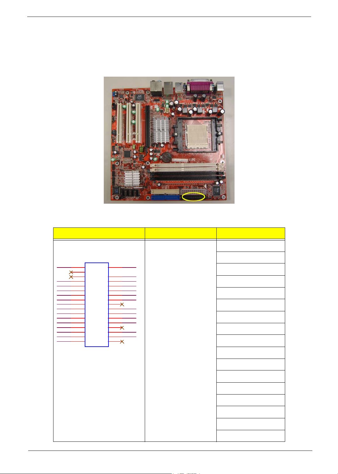
FDD (Floppy Connector)
The FDD connector is used to connect the FDD cable while the other end of the cable connects to the FDD
drive. The types of FDD drives supported are 1.44MB and 2.88MB.Please connect the red power connector
wire to the pin1 position.
DENSELJ
INDEXJ
MOTEAJ
DRVBJ
DRVAJ
MOTEBJ
DIRJ
STEPJ
WDATAJ
WGATEJ
TK00 J
WPTJ
RDATAJ
SIDE1J
DSKCHGJ
Illustration Jumper / Header Name Pin No. and definition
34-pin Floppy 1: GND
5: GND
GND
2
2
4
4
6
6
8
8
10
10
12
12
14
14
16
16
18
18
20
20
22
22
24
24
26
26
28
28
30
30
32
32
34
34
1
1
5
7
9
11
13
15
17
19
21
23
25
27
29
31
33
GND
5
GND
7
GND
9
GND
11
GND
13
GND
15
17
GND
19
GND
21
GND
23
GND
25
27
GND
29
GND
31
33
7: GND
9: GND
11: GND
13: GND
15: GND
17: N/C
19: GND
21: GND
23: GND
25: GND
27: N/C
29: GND
31: GND
33: N/C
2: DENSELJ
Chapter 5 88
Page 98

Illustration Jumper / Header Name Pin No. and definition
4: N/C
6: N/C
8: INDEXJ
10: MOTEAJ
12: DRVBJ
14: DRVAJ
16: MOTEBJ
18: DIRJ
20: SETPJ
22: WDATAJ
24: WGATEJ
26: TK00J
28: WPTJ
30: RDATAJ
32: SIDE1J
34: DSKCHGJ
IDE1 / IDE2 (IDE Connector)
An IDE device connects to the computer via an IDE connector. One IDE connector can connect to one IDE
cable, and the single IDE cable can then connect to two IDE devices (hard drive or optical drive). If you wish to
connect two IDE devices, please set the jumper on one IDE device as Master and the other as Slave.
89 Chapter 5
Page 99

Illustration Jumper / Header Name Pin No. and definition
IDE Header 1: SLOT_IDERST
SLOT_IDERST
ID E_PDD 7
ID E_PDD 6
ID E_PDD 5
ID E_PDD 4
ID E_PDD 3
ID E_PDD 2
ID E_PDD 1
ID E_PDD 0
GND
ID E_DR EQ_P
IDE_IOW_P*
IDE_IOR_P*
IDE_IORDY_P
IDE_DACK_P*
IDE_INTR_P
ID E_ADD R_P1
ID E_ADD R_P0
ID E_CS1_P*
P_HDLED*
1
3
5
7
9
11
13
15
17
19
X
21
23
25
27
29
31
33
35
37
39
2
ID E_PDD 8
4
ID E_PDD 9
6
ID E_PDD 10
8
ID E_PDD 11
10
ID E_PDD 12
12
ID E_PDD 13
14
ID E_PDD 14
16
ID E_PDD 15
18
22
24
26
28
30
32
CBLE_D ET_P
34
ID E_ADD R_P2
36
ID E_CS3_P*
38
40
GND
GND
GND
GND
GND
GND
GND
3: IDE_PDD7
5: IDE_PDD6
7: IDE_PDD5
9: IDE_PDD4
11: IDE_PDD3
13: IDE_PDD2
15: IDE_PDD1
17: IDE_PDD0
19: GND
21: IDE_DREQ_P
23: IDE_IOW_P*
25: IDE_IOR_P*
27: IDE_IORDY_P
29: IDE_DACK_P*
31: IDE_INTR_P
33: IDE_ADDR_P1
35: IDE_ADDR_P0
37: IDE_CS1_P*
39: P_HDLED*
2: GND
4: IDE_PDD8
6: IDE_PDD9
8: IDE_PDD10
10: IDE_PDD11
12: IDE_PDD12
14: IDE_PDD13
16: IDE_PDD14
18: IDE_PDD15
20: KEY
22: GND
24: WGATEJ
26: TK00J
Chapter 5 90
Page 100
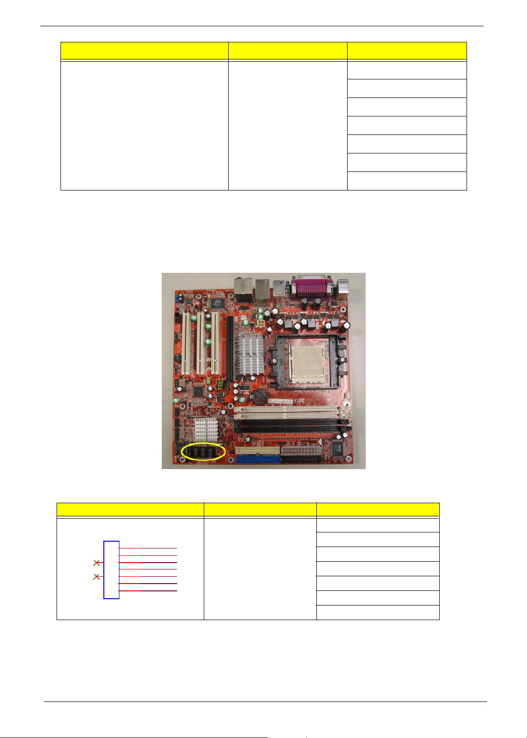
Illustration Jumper / Header Name Pin No. and definition
28: WPTJ
30: RDATAJ
32: SIDE1J
34: DSKCHGJ
36: IDE_ADDR_P2
38: IDE_CS3_P*
40: GND
SATA1 / SATA2 / SATA3 / SATA4 (Serial ATA Connector)
Please refer to the BIOS setting for the Serial ATA and install the proper driver in order to work properly.
Illustration Jumper / Header Name Pin No. and definition
7-pin SATA Header 1: GND
1
2
3
8
4
5
9
6
7
GND
SP_TX0P
SP_TX0M
GND
SP_RX0M
SP_RX0P
GND
2: SP_TX0P
3: SP_TX0M
4: GND
5: SP_RX0M
6: SP_RX0P
7: GND
91 Chapter 5
 Loading...