

Page 1

- 1
Predator
P09-600
User’s!Guide!
Page 2

Important
This manual contains proprietary information that is protected by
copyright laws. The information contained in this manual is subject to
change without notice. Images provided herein are for reference only
and may contain information or features that do not apply to your
computer. Acer Group shall not be liable for technical or editorial errors
or omissions contained in this manual.
!
2 -
© 2017. All Rights Reserved.
Desktop Computer Covers:
Tower models
This revision: November 2017 V1.00
Page 3

TABLE OF CONTENTS
Table of contents - 3
1
Upgrading your computer 5
Installation precautions ............................. 5
ESD precautions .......................................... 5
Required tools ............................................. 5
Pre-installation instructions .......................... 6
Post-installation instructions ........................ 6
System covers ........................................... 7
Removing the rear system cover ................. 7
Installing the rear system cover ................... 8
Removing the left side system cover ........... 9
Installing the left side system cover ........... 10
Hard drives .............................................. 11
Removing the 3.5-inch Easy Swap hard
drive ........................................................... 11
Installing the 3.5-inch Easy Swap hard
drive ........................................................... 14
Removing the 3.5-inch hard drives ............ 16
Installing the 3.5-inch hard drives .............. 21
Memory ................................................... 26
Memory configuration guidelines ............... 26
Removing a memory module ..................... 27
Installing a memory module ....................... 29
Graphic board ......................................... 32
Removing the graphic board ...................... 32
Installing the graphic board ....................... 35
SSD module ............................................ 37
Removing the SSD module ....................... 37
Installing the SSD module ........................ 39
2
PredatorSense 41
PredatorSense features .......................... 41
Page 4

1!Upgrading!your!Computer!
!
!
!
!
!
!
In this section, you will find:
• Instructions!on!ho w !!to!replace !!a!h a rd ware!! component!
Page 5

1 Upgrading your computer - 5
Note
The screws for the different components vary in size. During the disassembly
process, group the screws with their corresponding components to avoid
mismatches when putting back the components.
!
1 UPGRADING YOUR COMPUTER
Installation precautions
Before you install any computer component, we recommend that you
read the following sections. These sections contain important ESD
precautions along with pre-installation and post-installation
instructions.
ESD precautions
Electrostatic discharge (ESD) can damage your processor, disk
drives, expansion boards, and other components. Always observe the
following precautions before you install a computer component:
1.
Do not remove a component from its protective packaging until you
are ready to install it.
2.
Wear a wrist grounding strap and attach it to a metal part of the
computer before handling components. If a wrist strap is not
available, maintain contact with the computer throughout any
procedure requiring ESD protection.
Required tools
In performing the component replacement process, you will need the
following tools:
•
Philips screwdriver
•
Hex screwdriver
•
Flat screwdriver
•
Scissors
Page 6
6 - 1 Upgrading your
Warning
Not turning off the computer properly before you start installing the
components may cause serious damage. Do not attempt the
procedures described in the following sections unless you are a
qualified service technician.
Pre-installation instructions
Always observe the following before you install any component:
1.
Make sure that the ODD and card reader slot is empty.
2.
Turn off the power to the computer and all peripherals.
3.
Unplug the power cord from the computer.
4.
Unplug the network cable and all connected peripheral devices
from the computer.
5.
Place the computer on a flat, steady surface.
6.
Open your computer according to the instructions on Removing
the rear system cover on page 7 and Removing the left side
system cover on page 9.
7.
See the following sections for specific instructions on the
component you wish to install.
Post-installation instructions
Observe the following after installing a computer component:
1.
See to it that the components are installed according to the stepby- step instructions in their respective sections.
2.
Replace any expansion boards or peripherals that you removed
earlier.
3.
Replace the system covers. See Installing the left side system
cover on page 10 and Installing the rear system cover on
page 8.
4.
Connect the necessary cables.
5.
Turn on your computer.
Page 7
1 Upgrading your computer - 7
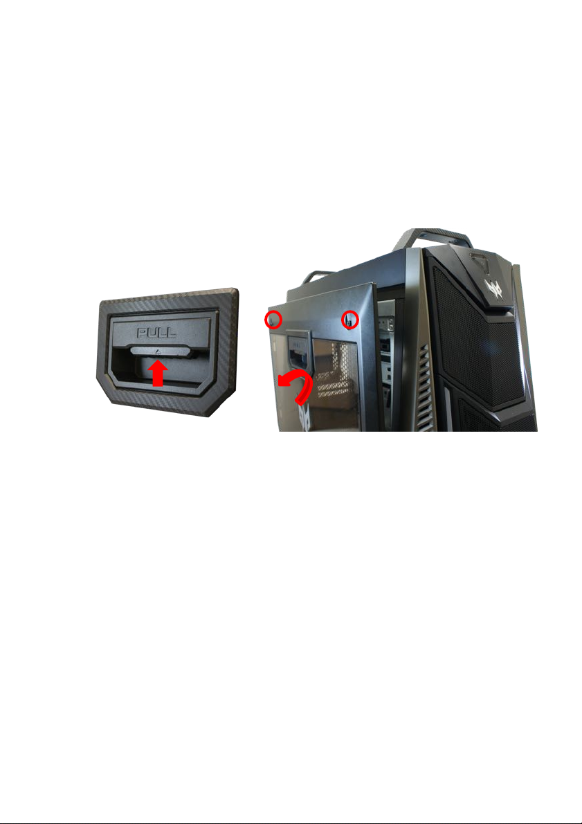
Removing the left side system cover
1.
Before you proceed, make sure that you have turned off your
computer and all peripherals connected to it. Read the Pre-
installation instructions on page 6.
2.
Remove the two screws that secure the system cover to the
computer.
3.
Slide the cover toward the back of the computer and pull away from
the side of the computer.
4.
Set the cover aside for re-installation later.
Page 8
8 - 1 Upgrading your
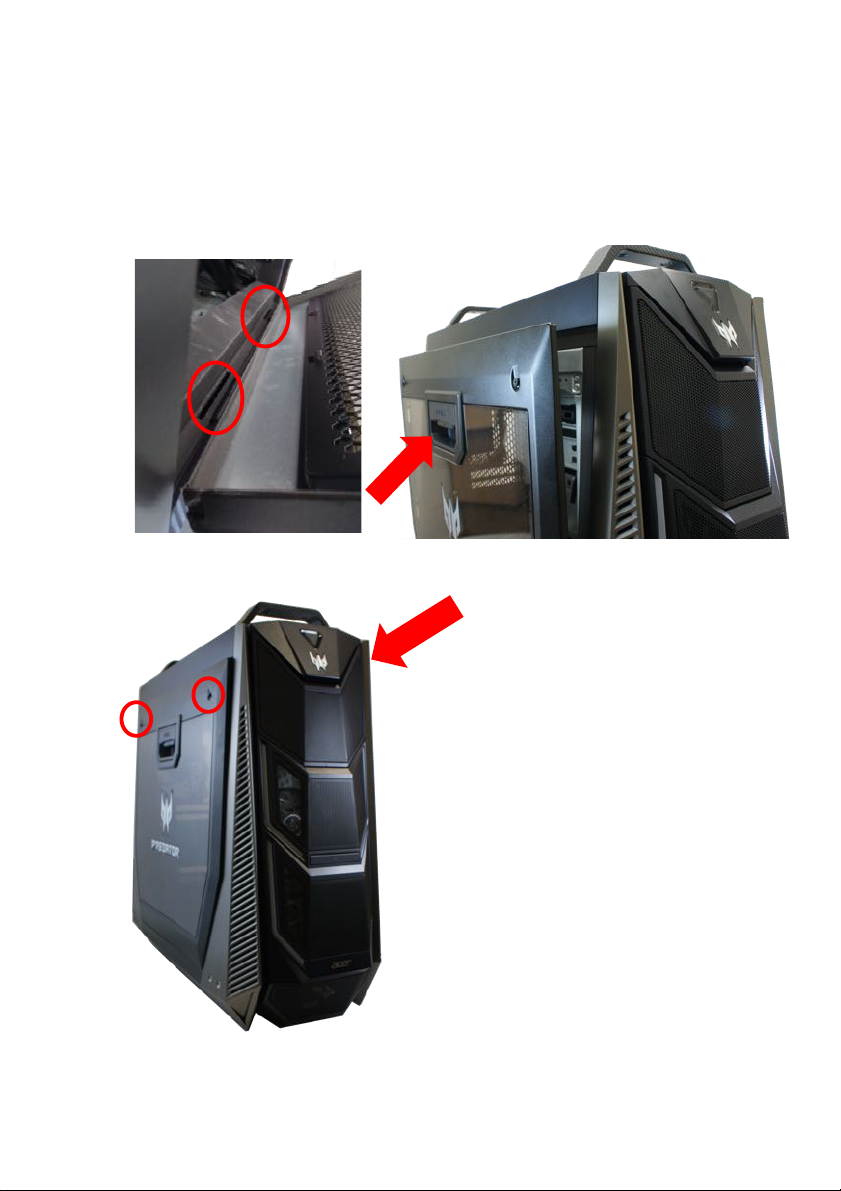
Installing the left side system cover
1.
Align the cover to the sides of the computer and slide the cover
toward the front of the computer.
2.
Secure the cover with two screws.
3.
Observe the Post-installation instructions on page 6.
Page 9
1 Upgrading your computer - 9
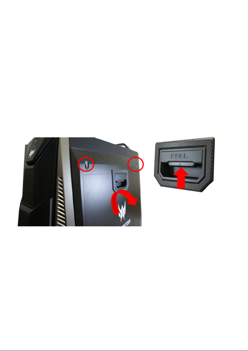
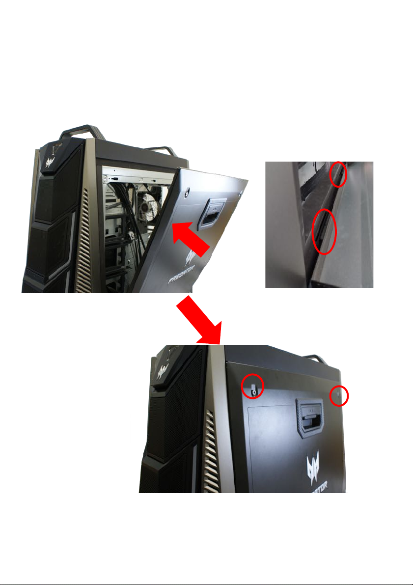
Removing the Right side system cover
1.
Before you proceed, make sure that you have turned off your
computer and all peripherals connected to it. Read the Pre-
installation instructions on page 6.
2.
Remove the two screws that secure the system cover to the
computer.
3.
Slide the cover toward the back of the computer and pull away from
the side of the computer.
4.
Set the cover aside for re-installation later.
Page 10
10 - 1 Upgrading your computer
Installing the Right side system cover
1.
Align the cover to the sides of the computer and slide the cover
toward the front of the computer.
2.
Secure the cover with two screws.
3.
Observe the Post-installation instructions on page 6.
Page 11
1 Upgrading your computer - 21
Hard drives
The computer supports installation of one 3.5-inch SATA hard
drives in the internal HDD cage.
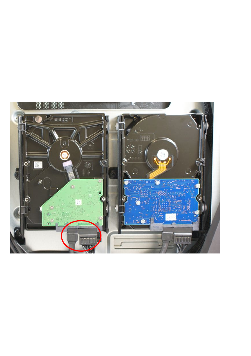
Removing the 3.5-inch hard drives
1.
Perform Pre-installation instructions on page 6.
2.
Disconnect the power and data cables from the hard drives.
Page 12
20 - 1 Upgrading your computer
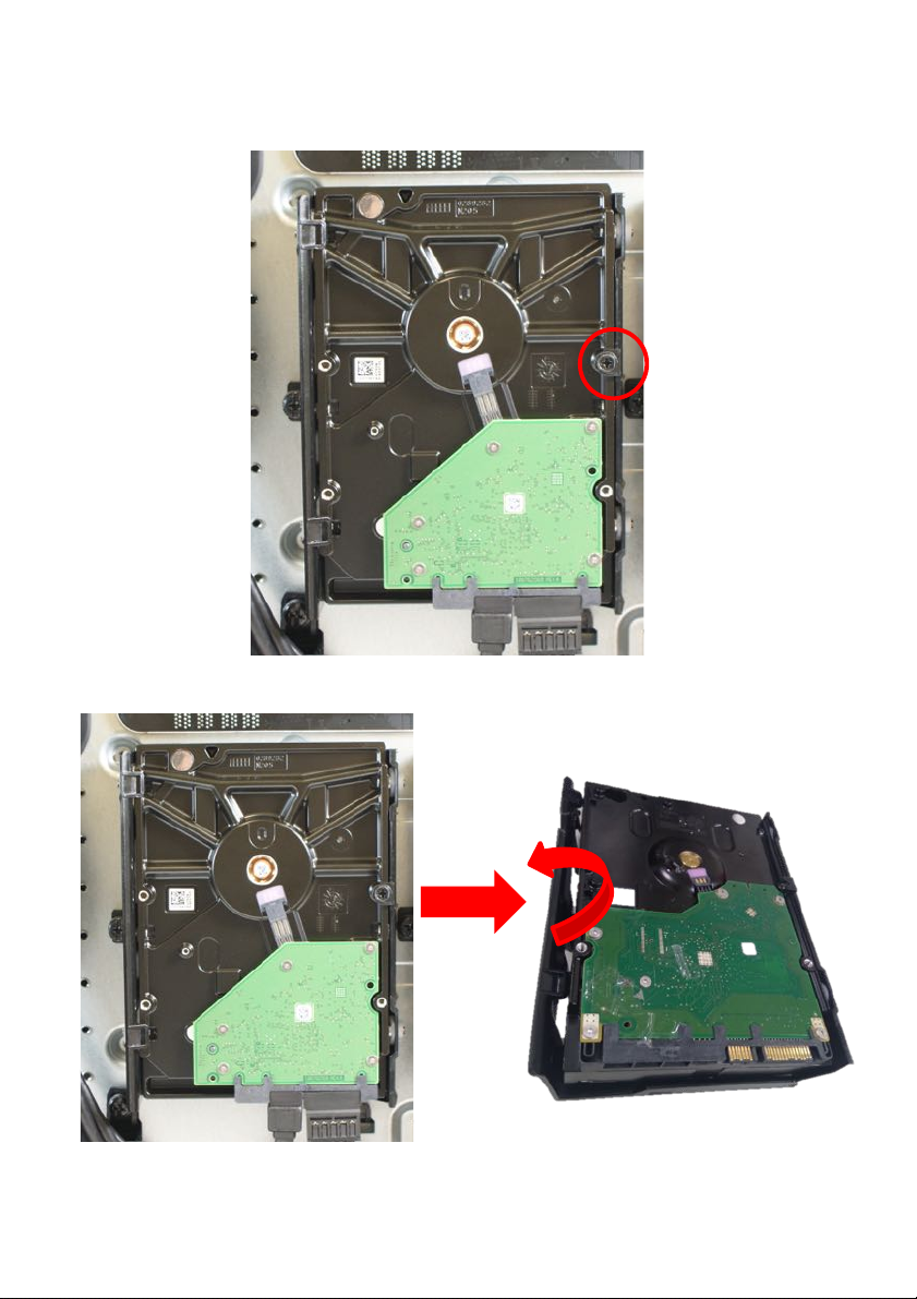
3.
Remove the one screws that secure the hard drives to the bracket
4.
Remove the hard drives from the bracket.
Page 13
1 Upgrading your computer - 21
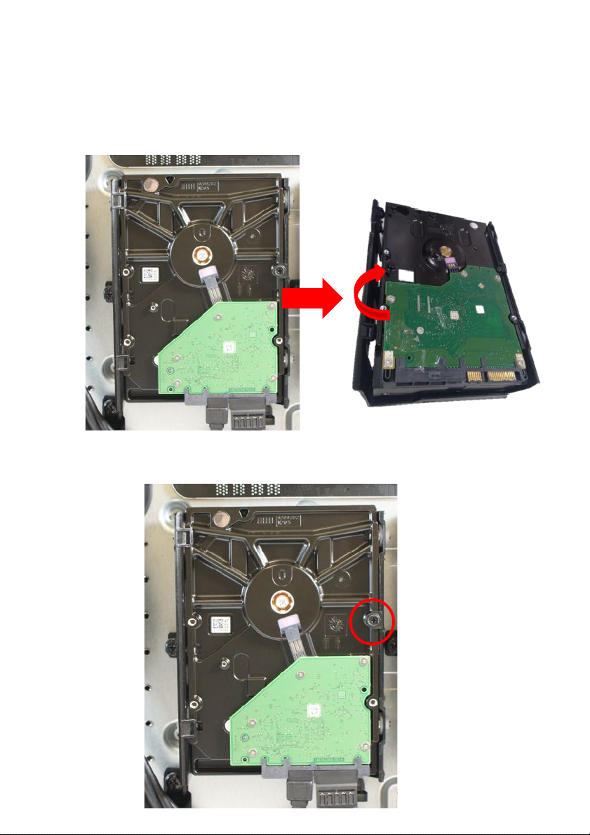
Installing the 3.5-inch hard drives
1.
Remove the new hard drive from their packaging.
2.
Insert the new hard drive into the bracket.
3.
Secure the new hard drive with one screws.
Page 14
14 - 1 Upgrading your
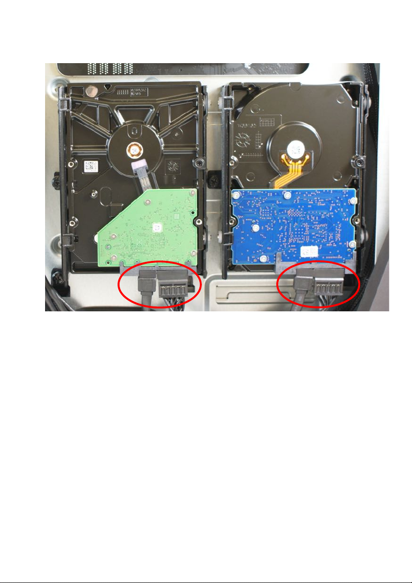
4.
Connect the power and data cables to the hard drive.
5.
Observe the Post-installation instructions on page 6
Page 15
1 Upgrading your computer - 15
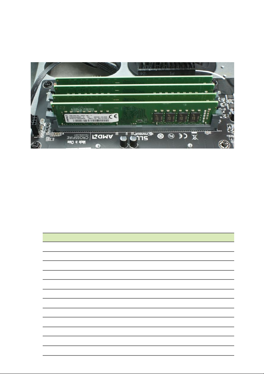
Memory
The computer has four DDR4 U-DIMM slots that support up to 64 GB
maximum system memory.
Memory configuration guidelines
•
To ensure data integrity, use only Acer-approved DDR4 2133 MHz
type memory modules.
•
Memory modules must be installed starting with DIMM3 slot.
•
Always handle memory modules by its edges.
•
When installing memory modules, populate the DIMM slots
according to the table below.
Size
DIMM1
DIMM2
DIMM3
DIMM4
4GB
N/A
N/A
4GB
N/A
8GB
N/A
N/A
4GB
4GB
12GB
4GB
N/A
4GB
4GB
16GB
4GB
4GB
4GB
4GB
8GB
N/A
N/A
8GB
N/A
16GB
N/A
N/A
8GB
8GB
24GB
8GB
N/A
8GB
8GB
32GB
8GB
8GB
8GB
8GB
16GB
N/A
N/A
16GB
N/A
32GB
N/A
N/A
16GB
16GB
48GB
16GB
N/A
16GB
16GB
64GB
16GB
16GB
16GB
16GB
DIMM1
DIMM2
DIMM3
DIMM4
Page 16
16 - 1 Upgrading your
Removing a memory module
1.
Perform Pre-installation instructions on page 6.
2.
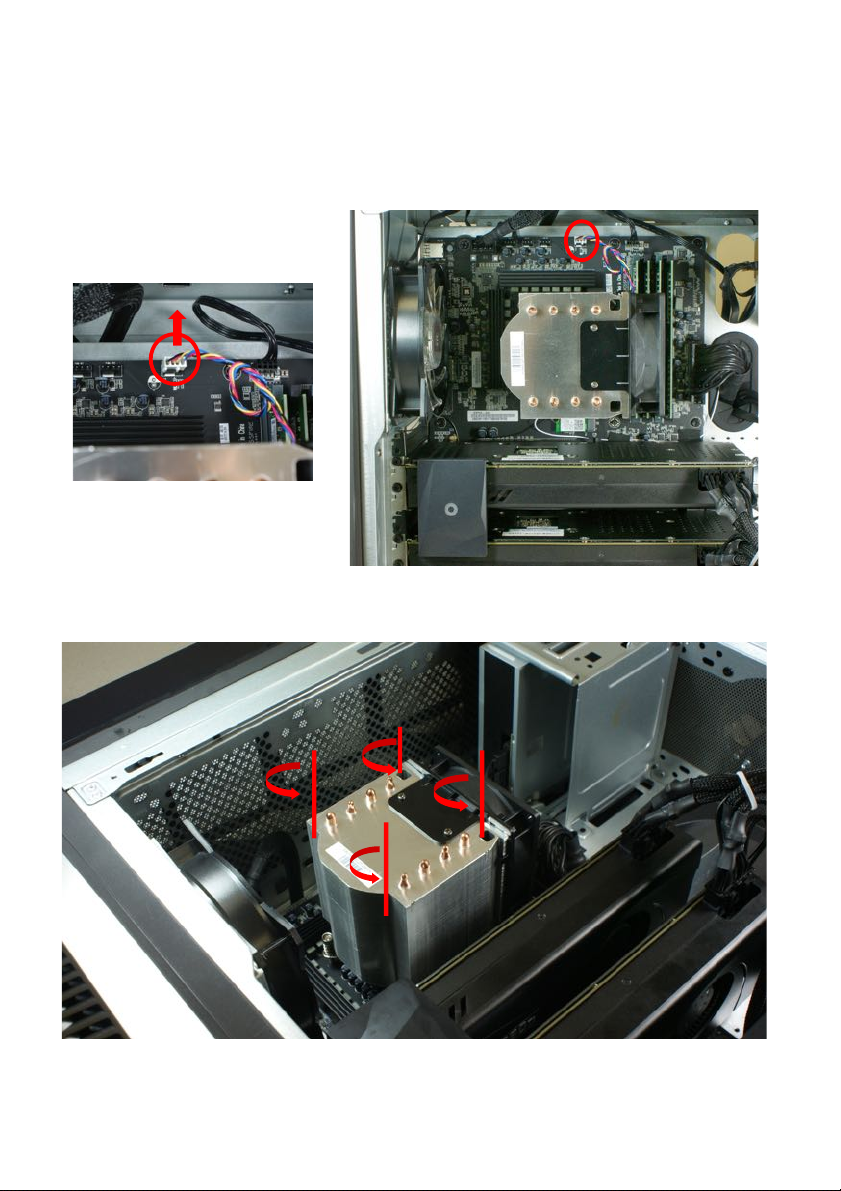
Disconnect the thermal fan cable from the mainboard.
3.
Use a long screw driver to loosen the four captive screws securing
the thermal module to the mainboard.
Page 17
1 Upgrading your computer - 17
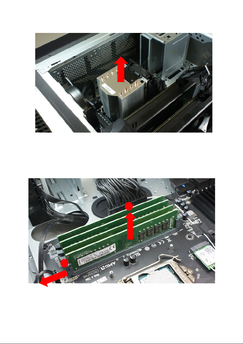
4.
Remove the thermal module from the chassis.
5.
Press outward the holding clips on both sides of the DIMM slot
outward to release the memory module (1).
6.
Gently pull the memory module upward to remove it from the DIMM
slot (2).
7.
Repeat steps 5~6 to remove the other memory modules.
2
1
Page 18
18 - 1 Upgrading your
Note
DIMM slots on the mainboard must be installed only in certain configurations.
Numbers next to DIMM slots correspond to installation sequence.
Be sure to install the memory module in DIMM1 slot followed by DIMM2 slot.
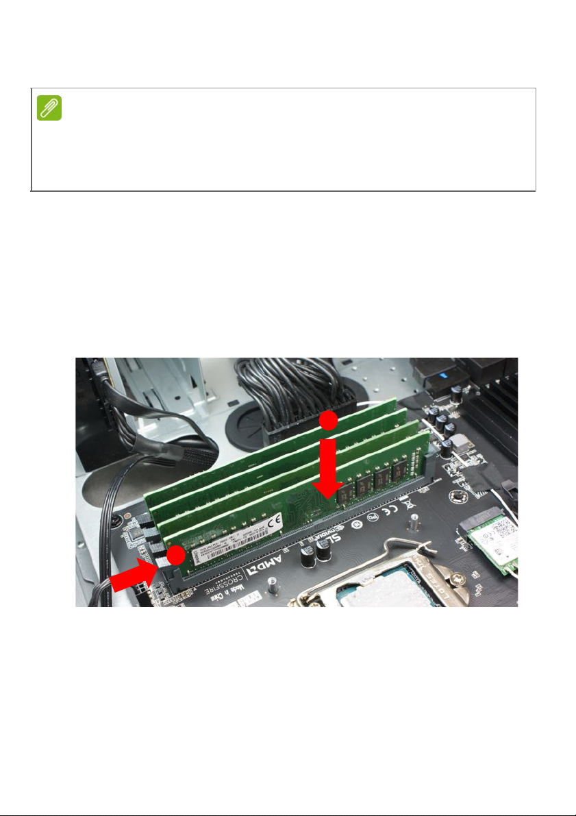
Installing a memory module
1.
Select an empty DIMM slot.
2.
Remove the new memory module from its packaging, handling it by
the edges.
3.
Align then insert the memory module into the DIMM slot (1).
4.
Insert the memory to the slot until the retaining clips snap inward (2).
The module is keyed so it can only be inserted in one direction. If the
module does not fit, make sure that the notch in the module lines up
with the tab in the memory slot.
5.
Repeat steps 1~4 to install the other memory modules.
1
2
Page 19
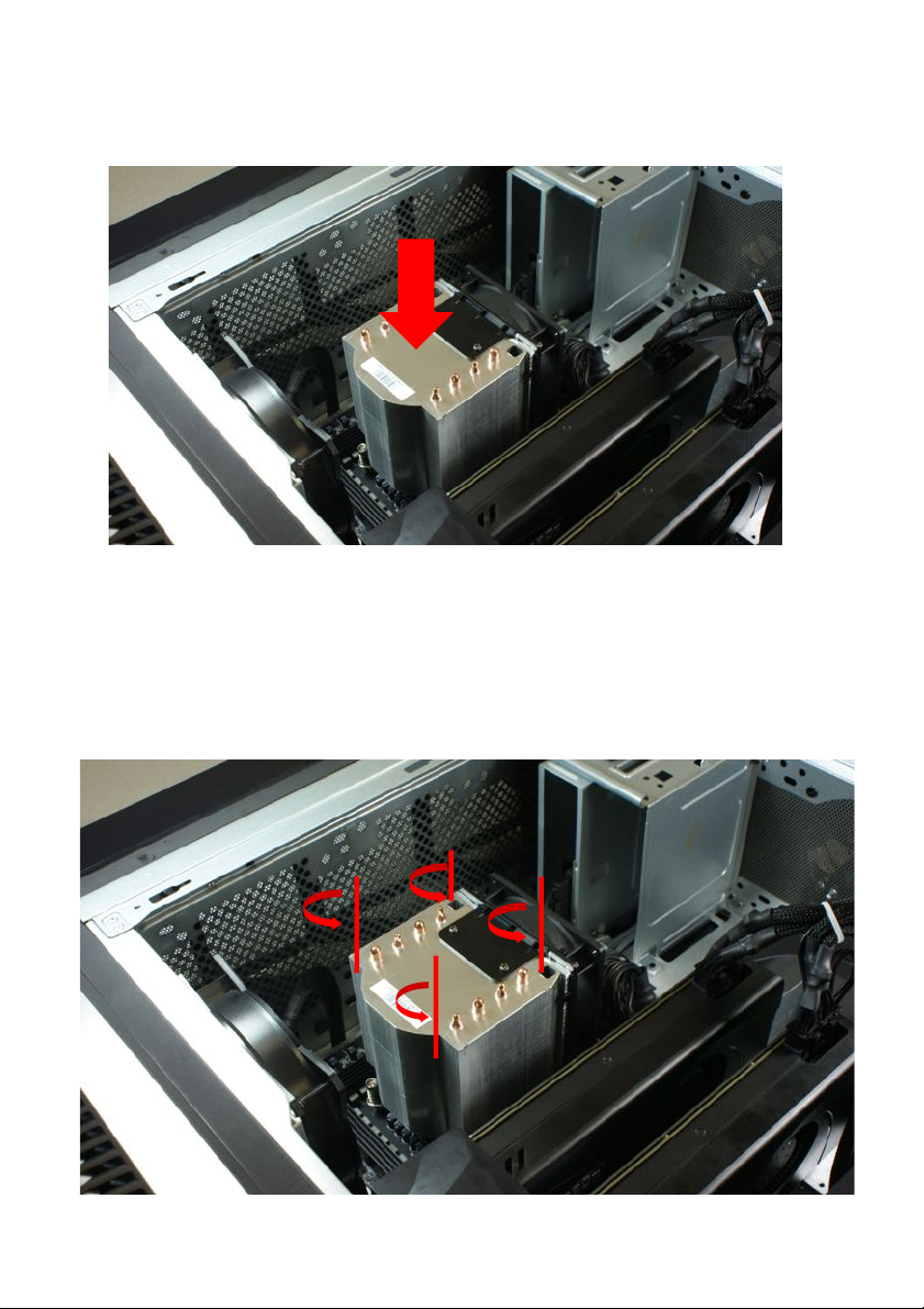
1 Upgrading your computer - 31
6.
Place the thermal module into the chassis.
7.
Use a long screw driver to tighten the four captive screws and
secure the thermal module to the mainboard.
Page 20
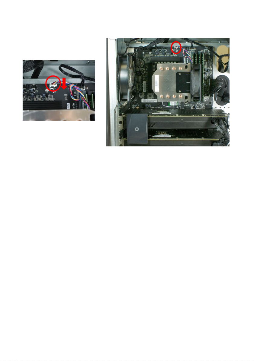
30 - 1 Upgrading your computer
8.
Connect the thermal fan cable to the mainboard.
9.
Observe the Post-installation instructions on page 6.
Page 21
32 - 1 Upgrading your
Graphic board
The computer contains one or two graphic boards installed in the PCIe
x16 slot.
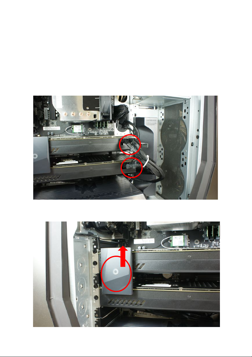
Removing the graphic board
1.
Perform Pre-installation instructions on page 6.
2.
Disconnect the power cables from the graphic boards.
3.
Disconnect the bridge from the graphic boards.
Page 22
1 Upgrading your computer - 33
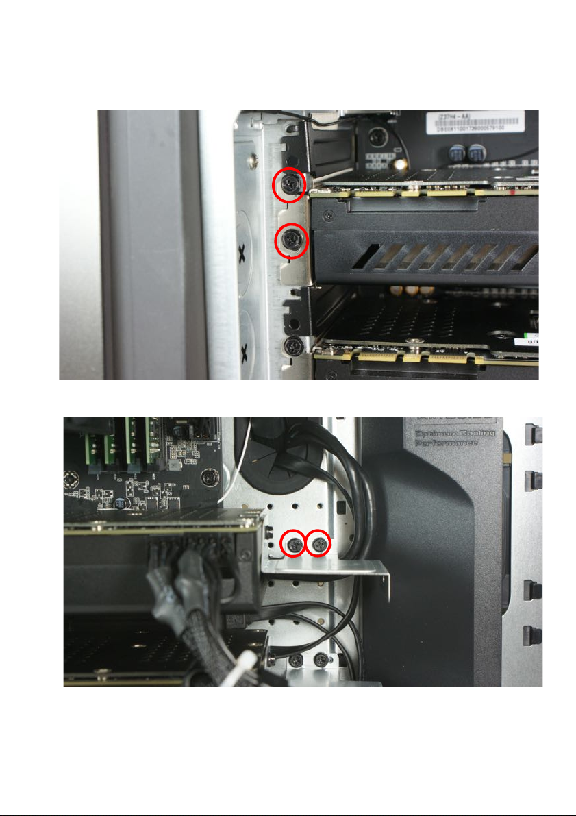
4.
Remove the screws that secure the graphic board to the chassis.
Page 23
34 - 1 Upgrading your
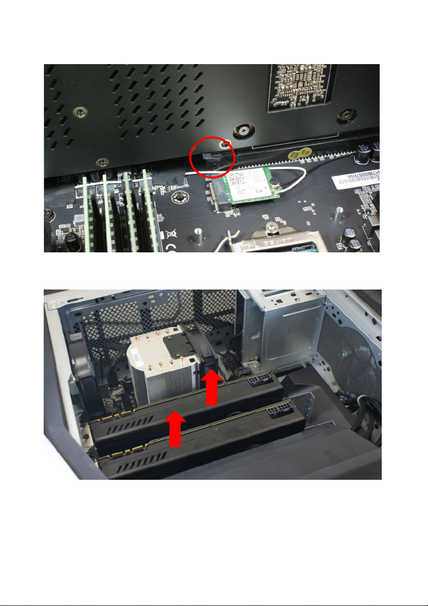
5.
Release the latch that secures the graphic board to the mainboard.
6.
Detach the graphic board from the PCIe x16 slot.
Page 24
1 Upgrading your computer - 35
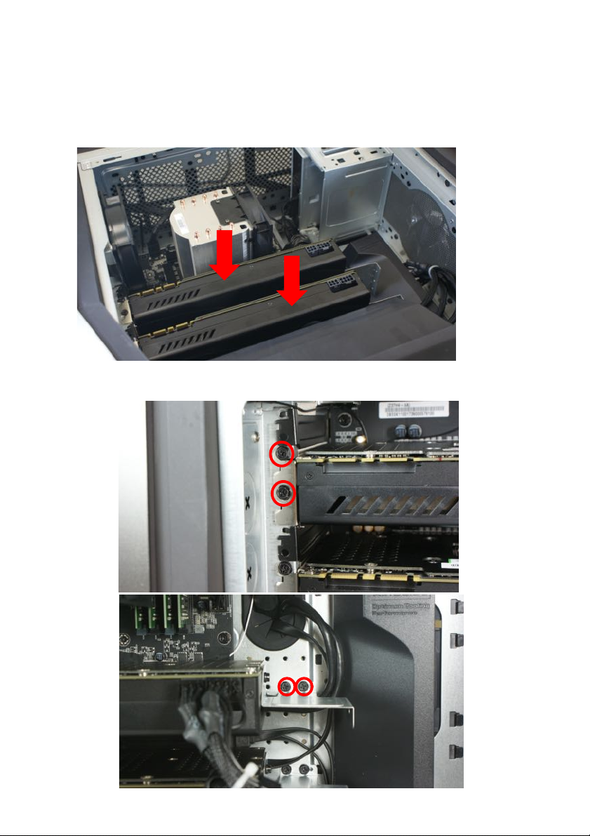
Installing the graphic board
1.
Remove the new graphic board from its packaging.
2.
Insert the graphic board into the PCIe x16 slot and press it down
until it latches into place.
3.
Secure the graphic board with one screw.
Page 25
36 - 1 Upgrading your
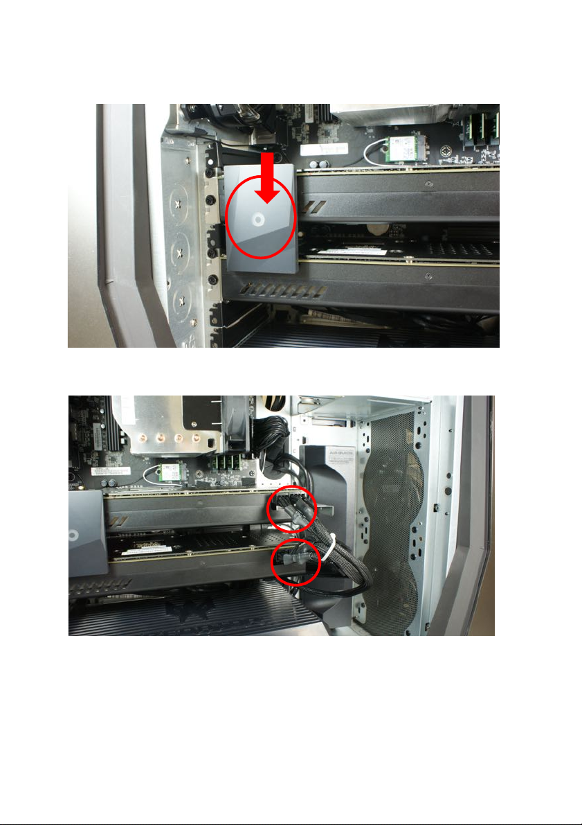
4.
Connect the bridge from the graphic board.
5.
Connect the power cables to the graphic board.
6.
Observe the Post-installation instructions on page 6
Page 26
1 Upgrading your computer - 37
M.2 SSD module
The computer contains one M.2 SSD module installed in the M.2
PCIe slot.
Removing the SSD module
1.
Perform Pre-installation instructions on page 6.
2.
Remove the graphic board. See Removing the graphic board
on page 32.
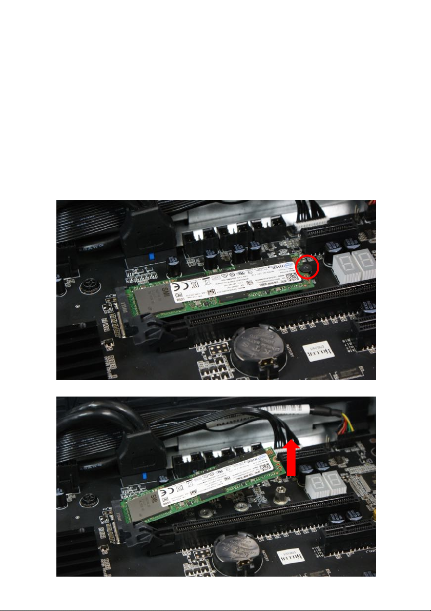
3.
Remove the screw that secures the M.2 SSD module to the
mainboard.
4.
Detach the M.2 SSD module from the mainboard.
Page 27
38 - 1 Upgrading your
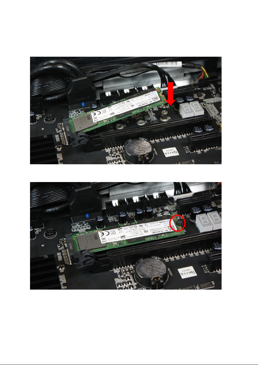
Installing the M.2 SSD module
1.
Remove the new M.2 SSD module from its packaging.
2.
Insert the M.2 SSD module into its slot in the mainboard.
3.
Secure the M.2 SSD module with one screw.
4.
Replace the graphic board. See Installing the graphic board on
page 35.
5.
Observe the Post-installation instructions on page 6.
Page 28

2!PredatorSense!
!
!
!
!
!
!
In this section, you will find:
• Introduc tio n !t o !th e !P re d a to rS e n s e!u t ility!
• How!to!use! PredatorSense!
Page 29
!
2 PREDATORSENSE
2 PredatorSense - 41
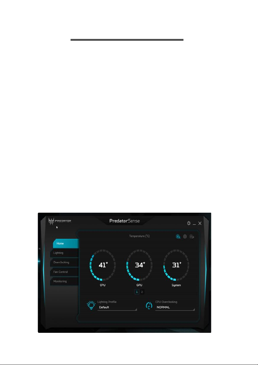
PredatorSense (DT) is an Acer proprietary utility to enhance the user
experience of Gaming products on Microsoft Windows 10.
The central idea of this utility is to provide a user interface to easily
control fan speed, RGB chassis and also display system information.
PredatorSense features
•
System information dashboard
•
Fan speed control
•
Lighting control
•
Overclocking
•
Monitoring
•
Advanced settings
•
Live update
To set up the PredatorSense application (Windows 10):
1.
From the Start menu, select All apps.
2.
Select Acer.
3.
Select PredatorSense.
Alternatively, you can double-click the PredatorSense desktop shortcut to
run the application.
Page 30

42 - 2 PredatorSense
Home Provide overview of all features with quick adjustment
l CPU/GPU/System health information
l Fan speed control (Auto, Gaming and Silence)
l Lighting profile
l CPU overlocking (Normal, Faster and Turbo)
Lighting
Provide control and adjustment for the LEDs on Front
Face, Left Side Face and Motherboard.
l On/Off
l Color: 9 basic colors (last one is rainbow color), 9 recent
colors which user creates the olor via More Color(palette)
button).
l Lighting Effects: None, Breathing, (Wave, Music, CPU
temp of Front face)
l Speed: Support Wave, CPU temp (Of Front face)
Overclocking Provide CPU overclocking in 3 levels, Normal, Faster and
Turbo level. And show the CPU loading, frequency, Max
frequency.
l The physical Turbo button will light on when OC level is
Faster level of Turbo level.
l Press physical Turbo button to switch OC level in Normal
level (light off) or Turbo level (light on).
l When resume from S3/S4/S5, PredatorSense will sync the
OC level from physical Turbo button.
Fan control Provide Fan speed control in Auto, Gaming and Custom
mode for 3 fans including CPU fan, Front fan and Back
fan. And show the fan speed for 3 fans. On the Custom
fan speed, user can adjust the fan speed in percentage.
l Custom fan speed only can control by 60 ~ 100%
percentage.
Category Description
Page 31

2 PredatorSense - 43
Monitoring Provide 3 tabs for CPU and GPU and System.
l Temperature in C/F
l Loading in %
l Frequency in MHz
l Voltage in V
l Fan speed in RPM
l Download/Upload in bytes/s of WIFI/Ethernet
l Usage in GB of RAM
Advanced settings
Provide control for Enable lighting effects in sleep mode and
Units of temperature.
Live update While user launches UI first time after a restart/boot while
network is available, UI will start to check Acer web service.
If there is any new update for PredatorSense, PredatorSense
will download (silently) and install (not silent install).
Category Description
 Loading...