

Page 1

AcerNote Nuovo
User’s Manual
Page 2

Copyright
Copyright © 1996 by Acer Incorporated. All rights reserved. No part of this
publication may be reproduced, transmitted, trans cribed, stor ed in a retr ieval
system, or translated into any language or computer language, in any form
or by any means, electronic, mechanical, magnetic, optical, chemical,
manual or otherwise, without the prior written permission of Acer
Incorporated.
Disclaimer
Acer Incorporated makes no representations or warranties, either expr essed
or implied, with respect to the contents hereof and specific ally disclaims any
warranties, merchantability or fitness for any particular purpose. Any Acer
Incorporated software described in this manual is sold or licensed “as is”.
Should the programs prove defective following their purchase, the buyer
(and not Acer Incorporated, its distributor, or its dealer) assumes the entire
cost of all necessary servicing, repair, and any incidental or consequential
damages resulting from any defect in the software. Further, Acer
Incorporated reserves the right to revise this publication and to make
changes from tim e to time in the contents hereof without obligation of Acer
Incorporated to notify any person of such revision or changes.
Acer is a registered trademark of Acer Incorporated. Microsoft, MS-DOS, Windows and
Windows 95 are registered t rademarks of Micros oft Corporati on. IBM and OS/2 are regis tered
trademarks of IBM Corporation. Intel and Pentium are registered trademarks of Intel
Corporation. Other brand and product names are trademarks and/ or registered trademark s of
their respective com pani es.
ii
Page 3

IMPORTANT SAFETY INSTRUCTIONS
1. Read these instructions carefully. Save these instructions for future
reference.
2. Follow all warnings and instructions marked on the product.
3. Unplug this product from the wall outlet before cleaning. Do not use
liquid cleaners or aerosol cleaners. Use a damp cloth for cleaning.
4. Do not use this product near water.
5. Do not place this product on an unstable cart, stand, or table. The
product may fall, causing serious damage to the product.
6. Slots and openings in the cabinet and the back or bottom are pr ovided
for ventilation; to ensure reliable operation of the produc t and to protect
it from overheating, these openings must not be blocked or covered.
The openings should never be blocked by placing the product on a bed,
sofa, rug, or other similar s urfac e. T his produc t should never be placed
near or over a radiator or heat register, or in a built- in installation unles s
proper ventilation is provided.
7. This product should be operated from the type of power indicated on the
marking label. If you are not sure of the type of power available, consult
your dealer or local power company.
8. Do not allow anything to rest on the power cord. Do not locate this
product where persons will walk on the cord.
9. If an extension cord is used with this product, make sur e that the total
ampere rating of the equipm ent plugged into the extension cord does
not exceed the extension cord am pere rating. Also, m ake s ure that the
total rating of all products plugged into the wall outlet does not exceed
the fuse rating.
10. Never push objects of any kind into this product through cabinet slots as
they may touch dangerous voltage points or short out parts that could
result in a fire or electric shock. Never spill liquid of any kind on the
product.
iii
Page 4

11. Do not attempt to service this product yourself, as opening or rem oving
covers may expose you to dangerous voltage points or other risks.
Refer all servicing to qualified service personnel.
12. Unplug this product from the wall outlet and refer servic ing to qualified
service personnel under the following conditions:
a. When the power cord or plug is damaged or frayed
b. If liquid has been spilled into the product
c. If the product has been exposed to rain or water
d. If the product does not operate normally when the operating
instructions are followed. Adjust only those controls that are
covered by the operating instructions since improper adjustm ent of
other controls may result in damage and will often require
extensive work by a qualified technician to restore the product to
normal condition.
e. If the product has been dropped or the cabinet has been damaged
f. If the product exhibits a distinct change in perform ance, indicating
a need for service
13. Replace battery with the same type as the product's battery we
recommend. Use of another battery may present a risk of fire or
explosion. Refer battery replacement to a qualified serviceman.
14. Warning! Battery may explode if not handled properly. Do not
recharge, disassem ble or dispose of in fire. Keep away from children
and dispose of used battery promptly.
15. Use only the proper type of power supply cord set (provided in your
accessories box) for this unit. It should be a detachable type: UL
listed/CSA certified, type SPT-2, rated 7A 125V minimum, VDE
approved or its equivalent. Maximum length is 15 feet (4.6 meters).
iv
Page 5

Concerning Lithium Batteries
ADVARSEL!
Lithiumbatteri - Eksplosionsfare ved fejlagtig håndtering.
Udskiftning må kun ske med batteri
af samme fabrikat og type.
Lever det brugte batteri tilbage til leverandøren.
A D V A R S E L
Eksplosjonsfare ved feilaktig skifte av batteri
Benytt samme batteritype eller en tilsvarende
type anbefalt av apparatfabrikanten.
Brukte batterier kasseres i henhold til fabrikantens
instruksjoner.
VARNING
Explosionsfara vid felaktigt batteribyte
Anvãnd samma batterityp eller en ekvivalent
typ som rekommenderas av apparattillverkaren.
Kassera anvãnt batteri enligt fabrikantens
instruktion
Canadian Department of Communications
Regulatory Statement
This digital apparatus does not exceed Class B limits for radio noise
emissions from digital apparatus set out in the Radio Interference
Regulations of the Canadian Department of Communications.
Le présent appareil numérique n'émet pas de bruits radio-électriques
dépassant les limites applic ables aux appareils numériques de la classe B
prescrites dans le Réglem ent sur le brouillage radioélectrique édicté par le
ministère des Communications du Canada.
v
Page 6

FCC Class B Radio Frequency Interference Statement
Note:
This equipment has been tested and found to comply with the limits for a
Class B digital device, pursuant to Part 15 of FCC Rules. Thes e limits are
designed to provide reasonable protection against harm ful interference in a
residential installation. This equipment generates, uses, and can radiate
radio frequency energy and, if not installed and used in accordance with the
instructions, may cause harmful interference to radio communications.
However, there is no guarantee that interference will not occur in a partic ular
installation. If this equipment does cause harmful interference to radio or
television reception, which can be determined by turning the equipment of f
and on, the user is encouraged to try to correct the interfer ence by one or
more of the following measures:
1. Reorient or relocate the receiving antenna.
2. Increase the separation between the equipment and receiver.
3. Connect the equipment into an outlet on a circuit diff erent from that to
which the receiver is connected.
4. Consult the dealer or an experienced radio/television technician for
help.
Notice 1:
The changes or modifications not expressly approved by the party
responsible for compliance could void the user's authority to operate the
equipment.
Notice 2:
Shielded interface cables, if any, must be used in order to comply with the
emission limits.
vi
Page 7

About This Manual
Purpose
This manual discusses the featur es of the notebook and tells how to use and
configure it.
Manual Structure
This manual consists of eight chapters and two appendices:
Chapter 1,
Chapter 2,
and its features.
Chapter 3,
on the unique power management system.
Chapter 4,
Chapter 5,
applications.
Chapter 6,
utility.
Chapter 7,
on travel.
Chapter 8,
in an easy Q&A format.
Appendix A,
Appendix B,
tables.
Getting Started
System Tour
, discusses issues on batter y use and includes inform ation
Power
Options
, tells how to connect and install hardware options.
Software
, explains how to configure the system with the BIOS Setup
Setup
Traveling with the Notebook
Troubleshooting
Specifications
Address and Interrupt Tables
, tells you how to get started with the notebook.
, gives a guided and in-depth “tour” of the notebook
, describes how to configure certain utilities and
, includes informative and us eful tips
, lists the steps you can take to resolve problem s
, lists the specifications of the notebook.
, shows the address and interrupt
vii
Page 8
Conventions
The following conventions are used in this manual:
C:\setup
[Enabled]
message displayed
E,H,U
,
, etc.
, etc
Represent text input by the user, default settings
and recommended selections
Denotes actual messages that appear on screen
Represent the actual keys that you have to press
on the keyboard
NOTE
Gives bits and pieces of additional information
related to the current topic
WARNING
Alerts you if damage may result from doing or not
doing specific actions
CAUTION
Gives precautionary measures to avoid possible
hardware or software problems
IMPORTANT
Reminds you to take action relevant to the
accomplishment of the procedure at hand
TIP
Tells how to complete a procedur e with minimum
steps through little shortcuts
viii
Page 9

Table of Contents
1 Getting Started
1.1 Item Checklist............................................................................................1-2
1.2 Taking Care of Your Computer .................................................................1-3
1.2.1 Notebook......................................................................................1-3
1.2.2 AC Adapter...................................................................................1-6
1.2.3 Battery Pack.................................................................................1-6
1.2.4 Cleaning and Servicing ................................................................1-7
1.2.5 Diskettes.......................................................................................1-7
1.3 Connecting the Notebook..........................................................................1-9
1.4 Creating Backup and Startup Diskettes..................................................1-10
1.5 Getting Help Online.................................................................................1-11
2 System Tour
2.1 Features....................................................................................................2-2
2.2 Display.......................................................................................................2-4
2.3 Indicator Lights..........................................................................................2-7
2.4 Keyboard...................................................................................................2-8
2.4.1 Keyboard Layout ..........................................................................2-8
2.4.2 Special Keys.................................................................................2-9
2.4.3 Automatic Tilt Feature................................................................2-16
2.4.4 Palm Rest...................................................................................2-17
2.5 Touchpad ................................................................................................2-18
ix
Page 10

2.6 Storage ...................................................................................................2-20
2.6.1 Hard Disk...................................................................................2-20
2.6.2 Module Bay................................................................................2-20
2.7 Ports .......................................................................................................2-23
2.7.1 Left Panel Ports......................................................................... 2-23
2.7.2 Rear Panel Ports .......................................................................2-26
2.8 Audio....................................................................................................... 2-28
2.8.1 Built-in Speakers and Microphone............................................. 2-28
2.8.2 Controlling the Audio.................................................................. 2-29
2.9 Communications.....................................................................................2-30
2.9.1 Serial Infrared............................................................................ 2-30
2.9.2 Fax/Data Modem....................................................................... 2-31
2.10 Securing your Notebook .........................................................................2-32
2.10.1 Security Notch............................................................................ 2-32
2.10.2 System Resource Lock..............................................................2-32
3Power
3.1 Battery Power ...........................................................................................3-2
3.1.1 Battery Pack Characteristics........................................................3-2
3.1.2 Removing and Installing the Battery Pack................................... 3-3
3.1.3 Charging the Battery....................................................................3-4
3.1.4 Checking the Battery Level..........................................................3-5
3.1.5 Optimizing Battery Life................................................................. 3-7
3.1.6 Battery Low Condition.................................................................. 3-8
x
Page 11

3.2 Power Management ................................................................................3-10
3.2.1 The Concept of Heuristics..........................................................3-10
3.2.2 Suspend Modes .........................................................................3-11
3.2.3 Advanced Power Management (APM).......................................3-14
4 Options
4.1 External Monitor ........................................................................................4-2
4.2 External Keyboard.....................................................................................4-3
4.3 External Keypad........................................................................................4-4
4.4 External Pointing Device ...........................................................................4-5
4.5 Printer........................................................................................................4-7
4.6 Audio Devices ...........................................................................................4-8
4.7 Mini Dock...................................................................................................4-9
4.8 PC Cards...................................................................................................4-9
4.9 Miscellaneous Options ............................................................................4-10
4.9.1 Additional Power Packs..............................................................4-10
4.9.2 Cables ........................................................................................4-12
4.10 Key Component Upgrades......................................................................4-14
4.10.1 Additional Memory......................................................................4-14
4.10.2 Hard Disk....................................................................................4-16
xi
Page 12

5 Software
5.1 System Software....................................................................................... 5-2
5.2 Sleep Manager..........................................................................................5-3
5.2.1 Accessing the Sleep Manager.....................................................5-3
5.2.2 Sleep Manager Functions............................................................5-5
5.2.3 Running Sleep Manager ..............................................................5-8
5.2.4 Sleep Manager Troubleshooting Tips..........................................5-9
5.2.5 Uninstalling Sleep Manager....................................................... 5-10
5.3 Touchpad Driver .....................................................................................5-12
5.3.1 Configuring the Touchpad .........................................................5-12
5.4 XingMPEG.............................................................................................. 5-13
5.5 Re-installing System Drivers and Applications .......................................5-14
6Setup
6.1 When to Use Setup ..................................................................................6-2
6.2 Entering Setup..........................................................................................6-3
6.3 About My Computer.................................................................................. 6-4
6.4 System Configuration ...............................................................................6-7
6.4.1 Date and Time............................................................................. 6-7
6.4.2 Diskette Drives............................................................................. 6-8
6.4.3 Hard Disks................................................................................... 6-8
6.4.4 Num Lock After Boot ................................................................... 6-8
6.4.5 LCD Expansion Mode..................................................................6-8
6.4.6 Internal Cache ...........................................................................6-10
6.4.7 External Cache.......................................................................... 6-11
xii
Page 13

6.4.8 Enhanced IDE Features.............................................................6-11
6.4.9 Onboard Communication Ports..................................................6-12
6.4.10 Onboard Audio...........................................................................6-15
6.4.11 Reset PnP Resources................................................................6-16
6.5 Power Saving Options.............................................................................6-17
6.5.1 When Lid is Closed ....................................................................6-18
6.5.2 Suspend to Disk on Critical Battery............................................6-19
6.5.3 Display Always On......................................................................6-19
6.5.4 Internal Speaker.........................................................................6-19
6.5.5 External Mouse Location............................................................6-19
6.5.6 Internal Modem ..........................................................................6-20
6.5.7 Resume On Modem Ring...........................................................6-20
6.5.8 Resume On Schedule................................................................6-20
6.5.9 Resume Date / Resume Time....................................................6-20
6.6 System Security.......................................................................................6-21
6.6.1 Supervisor and User Passwords................................................6-22
6.6.2 Diskette Drive Control ................................................................6-23
6.6.3 Hard Disk Drive Control..............................................................6-24
6.6.4 Start Up Sequences...................................................................6-24
6.6.5 Flash New BIOS.........................................................................6-25
6.7 Reset to Default Settings.........................................................................6-26
7 Traveling with the Notebook
7.1 Travel Preparations...................................................................................7-2
7.2 International Traveler’s Warranty..............................................................7-3
7.3 Worldwide Support....................................................................................7-4
xiii
Page 14

8 Troubleshooting
8.1 Q & A ........................................................................................................8-2
8.2 POST Error Messages.............................................................................. 8-7
A Specifications
B Address and Interrupt Tables
B.1 System Memory Map................................................................................B-1
B.2 I/O Address Map.......................................................................................B-2
B.3 Interrupt Levels .........................................................................................B-3
B.4 DMA Channels..........................................................................................B-3
xiv
Page 15

List of Figures
1-1 Write-protecting a 3.5-inch Diskette..........................................................1-8
2-1 Display.......................................................................................................2-5
2-2 Indicator Lights..........................................................................................2-7
2-3 Keyboard Layout .......................................................................................2-8
2-4 Palm Rest................................................................................................2-17
2-5 Touchpad ................................................................................................2-18
2-6 Module Bay..............................................................................................2-20
2-7 Left Panel Ports.......................................................................................2-23
2-8 Rear Panel Ports.....................................................................................2-26
2-9 Built-in Speakers and Microphone ..........................................................2-28
4-1 Connecting an External Monitor................................................................4-2
4-2 Connecting an External Keyboard.............................................................4-3
4-3 Connecting an External Keypad................................................................4-4
4-4 Connecting an External Pointing Device...................................................4-5
4-5 Connecting a Parallel Printer.....................................................................4-7
4-6 Connecting Audio Devices........................................................................4-8
4-7 Mini Dock...................................................................................................4-9
4-8 Using the File Transfer Cable..................................................................4-13
xv
Page 16

List of Tables
2-1 Indicator Status Descriptions.................................................................... 2-7
2-2 Lock Key Descriptions..............................................................................2-9
2-3 Using the Embedded Keypad................................................................. 2-10
2-4 Windows 95 Key Descriptions................................................................ 2-11
2-5 Hot Key List............................................................................................. 2-12
2-6 Eject Menu Descriptions......................................................................... 2-15
2-7 Touchpad Functions...............................................................................2-19
2-8 Left Panel Port Descriptions................................................................... 2-24
2-9 Rear Panel Port Descriptions .................................................................2-27
2-10 Audio Control Hot Keys........................................................................... 2-29
3-1 Battery-level Chart ....................................................................................3-6
3-2 Course of Action for Battery-low Condition...............................................3-9
4-1 Memory Configurations...........................................................................4-14
4-2 Hard Disk List .........................................................................................4-16
5-1 Sleep Manager Window Items.................................................................. 5-4
5-2 Sleep Manager Error Messages and Solutions........................................ 5-9
5-3 Location of Drivers..................................................................................5-14
5-4 Location of Applications..........................................................................5-15
6-1 About My Computer Item Descriptions.....................................................6-5
6-2 Diskette Drive Control Settings............................................................... 6-23
xvi
Page 17

6-3 Hard Disk Drive Control Settings.............................................................6-24
6-4 Start Up Sequences Settings..................................................................6-24
8-1 POST Error Messages..............................................................................8-7
xvii
Page 18

Getting Started
Congratulations on your purchase of the award-winning AcerNote Nuovo
notebook computer. Guar anteed and backed by Acer’s world-class support,
you can be sure of top-notch performance with your new AcerNote. This
chapter guides you through the first few steps on setting up your notebook
computer.
Chapter 1
Getting Started 1-1
Page 19

1.1 Item Checklist
Carefully unpack the carton and remove the contents. If any of the following
items is missing or damaged, contact your dealer immediately.
Notebook computer
•
Accessory box
•
AC adapter
•
Battery pack
•
Floppy drive module
•
External floppy drive cable
•
User’s manual and other documentation
•
Check for optional items, if any.
1-2 User’s Manual
Page 20
1.2 Taking Care of Your Computer
Your computer will serve you well if you take care of it. This section tells you
how to care for the notebook. Also, re-r ead the important s afety instructions
at the beginning of this manual.
1.2.1 Notebook
•
•
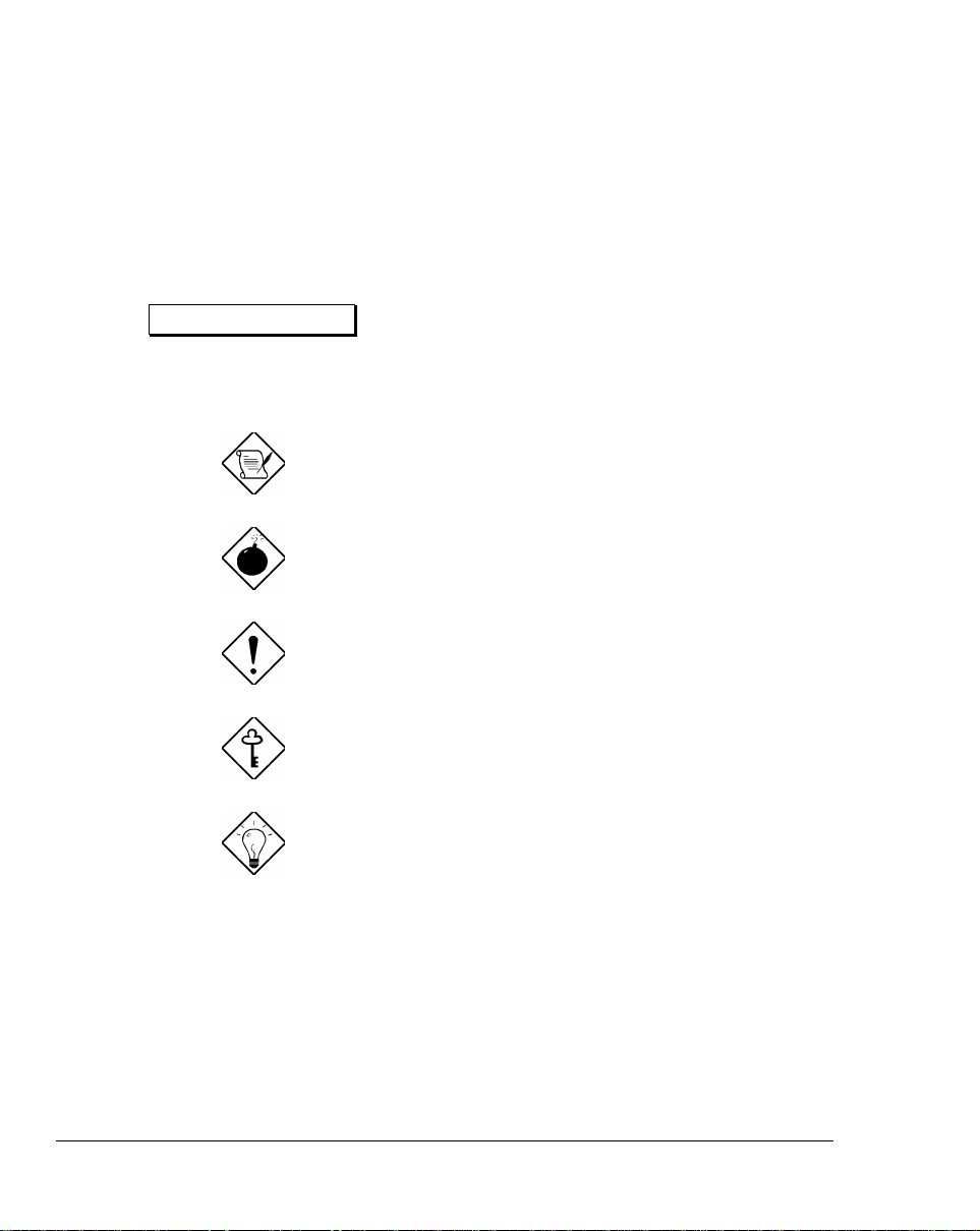
Do not expose the notebook to
direct sunlight. Do not place
near sources of heat, such as a
radiator.
Do not expose to temperatures
below 0ºC (32ºF)
or
above 50ºC (122ºF).
Getting Started 1-3
Page 21
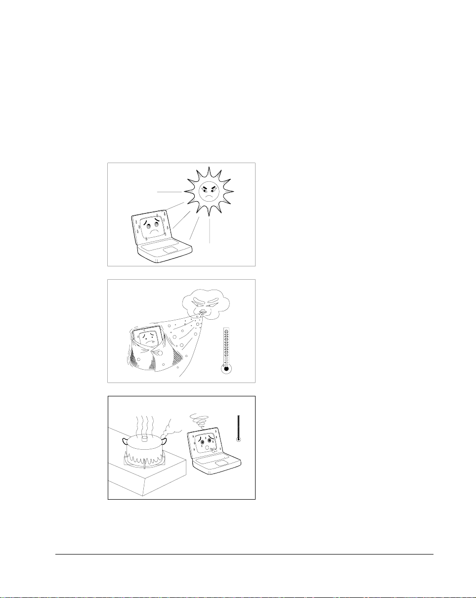
Do not subject the notebook to
•
magnetic fields.
Do not expose the notebook to
•
rain or moisture.
Do not spill water on the
•
notebook.
Do not subject the computer to
•
heavy shock and vibration.
1-4 User’s Manual
Page 22
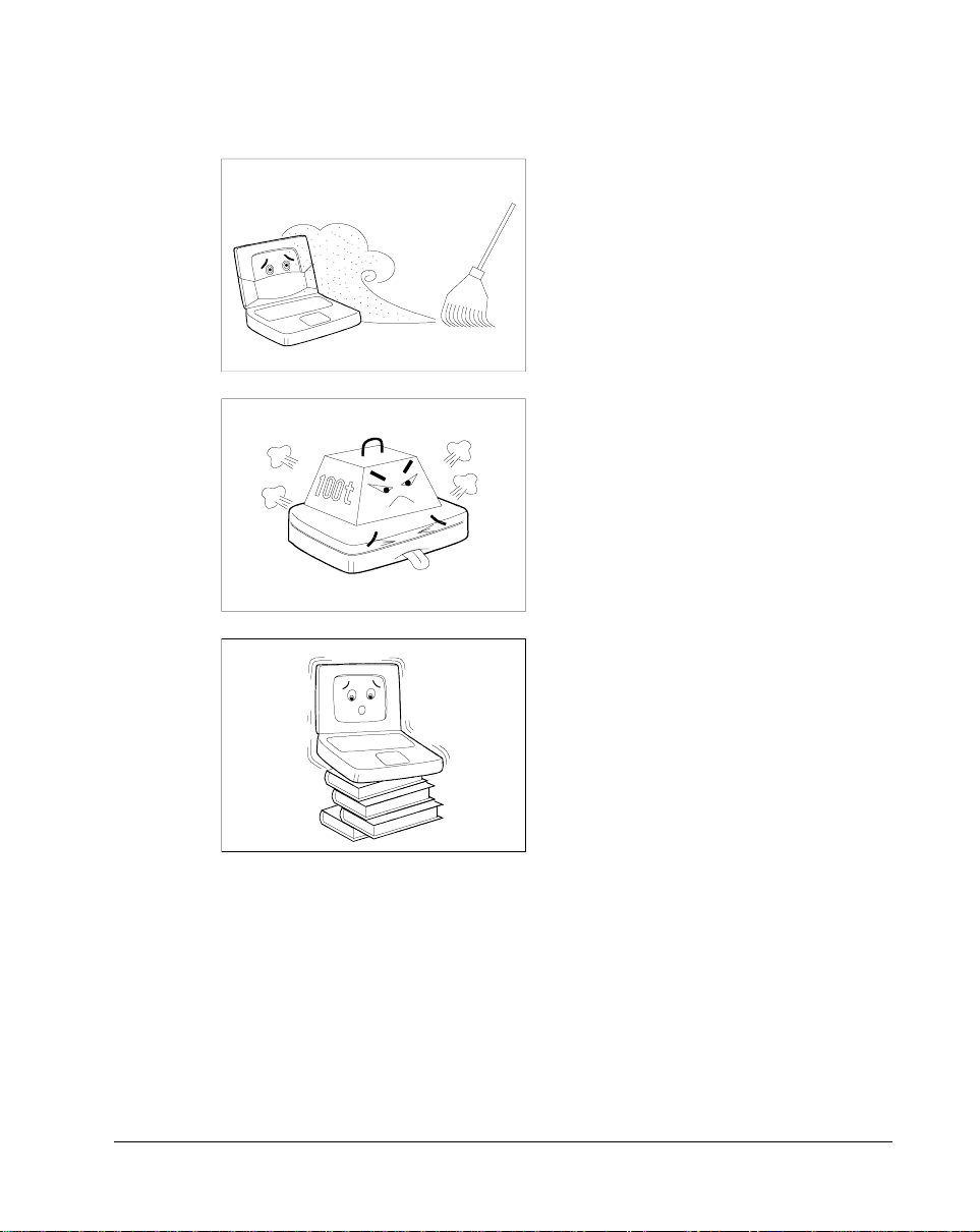
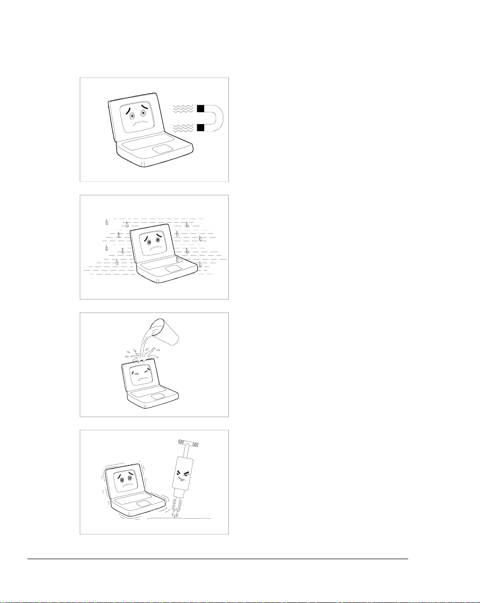
Do not expose the notebook to
•
dust and dirt.
Never place objects on top of
•
the notebook to avoid
damaging the notebook.
Never place the notebook on
•
uneven surfaces.
Getting Started 1-5
Page 23

1.2.2 AC Adapter
The AC adapter provides uninterrupted power to your notebook and charges
your battery pack. Here are some ways of taking care of your AC adapter.
Do not connect the adapter to any other device.
•
Do not step on the power cord or place heavy objects on top of it.
•
Carefully route the power cord and any cables away from personal
traffic.
When unplugging the power cor d, pull on the plug and not on the cord
•
itself.
1.2.3 Battery Pack
The long-lasting Lithium-Ion (Li-Ion) rechargeable battery pack gives you
power on-the-go. Here are some things to keep in mind regarding your
battery pack.
Caution:
Replace the battery pack with the same type (Model Name: BTP-S31)
•
Battery pack is suitable for use only with this notebook model
•
Burn hazard. Do not disassemble. Handle dam aged or leak ing lithium -
•
ion battery with extreme care. If the battery is damaged, electrolyte may
leak from the cells and may cause personal injury.
There may be local restrictions on the dis posal or recycling of batteries;
•
consult your local regulations or waste disposal provider.
Do not expose to high temperatures (50°C / 122°F)
•
1-6 User’s Manual
Page 24

1.2.4 Cleaning and Servicing
When cleaning the notebook, follow these steps:
1. Close the display lid to turn the notebook off.
2. Disconnect the AC adapter.
3. Remove the battery pack.
4. Use a soft cloth moistened with water. Do not use liquid or aerosol
cleaners.
Contact your dealer or see your service technician if any of the following
occurs:
Notebook has been dropped or damaged.
•
Liquid has been spilled into the product.
•
The notebook does not operate normally.
•
See section 7.3 for contact information.
1.2.5 Diskettes
Following are some tips on diskette management:
Always make backup copies of diskettes that c ontain important data or
•
program files.
Keep diskettes away from magnetic fields and sources of heat.
•
Avoid removing a diskette from a drive when the floppy drive activity
•
light is on.
Getting Started 1-7
Page 25

d
d
Write- protect your diskettes to prevent accidental erasure. T o do this,
•
slide the write-protect tab to the write-protect position.
Write-protecte
Not write-protecte
Figure 1-1 Write-protecting a 3.5-inch Diskette
When you put a label on a 3.5-inch diskette, mak e sure that the label is
•
properly attached (flat on the surface) and within the labelling area (area
with slight surface depression) on the diskette. An im properly attached
label may cause a diskette to get stuck in the drive when you are
inserting or removing it.
1-8 User’s Manual
Page 26
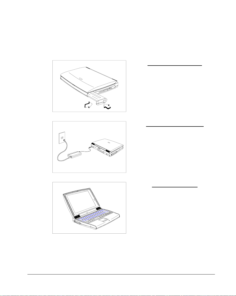
1.3 Connecting the Notebook
After reading through the previous section, you are now ready to experience
your new notebook. Connecting the notebook is as easy as 1-2-3.
Inserting the Battery Pack
Insert the battery pack into the
battery compartment and slide the
battery compartment cover in place.
Connecting the AC Adapter
Connect one end of the AC adapter
to the DC-in port on the notebook’s
rear panel and the other end to a
properly grounded power outlet.
Turning on the Power
Slide the display cover latch to the
right and open the display to turn on
the power.
Getting Started 1-9
Page 27

1.4 Creating Backup and Startup Diskettes
Entering User Information
When Windows 95 loads for the first tim e, enter your user inf ormation. Have
your Windows 95 authentication number ready, found in the Windows 95
documentation package.
Creating Backup and Startup Diskettes
Windows 95 prompts you to create backup and startup diskettes.
If your Windows 95 package contains a W indows 95 CD-ROM,
you do not need to create backup diskettes for Windows 95.
However, you may need to create the Windows 95 startup disk.
At this point, you need to create the notebook backup dis k which allows you
to boot-up your notebook from the floppy drive and access the CD-ROM
drive for W indows 95 and driver re-installation in case of a har d disk crash
(when the hard disk is not functioning proper ly and cannot be accessed) or
when your system cannot startup Windows 95. See the backup kit for
details.
If you do not wish to perform the backup at this time, you can skip through
this step during Windows 95 setup. Access the Create System Disk tool
when you wish to do so. However, we suggest you create the disk(s) as
soon as possible.
1-10 User’s Manual
Page 28

1.5 Getting Help Online
This user’s manual provides clear and concise information about the
notebook, so read it thoroughly. To provide you with help when traveling, the
notebook has a comprehensive online help.
Accessing Online Help
Follow these steps to access the online documentation:
1. Press the Windows logo button or Click on the Start button.
2. Select Programs.
3. Click on AcerNote Nuovo.
4. Select Online Manual.
The online help is easy to navigate with hypertext and hypergraphics. Clear
illustrations help describe notebook operation as well.
Getting Online
If you are connected to the Internet and have World W ide Web acces s, visit
our home page (http://www.acer.com /) and get the latest information about
our products, as well as updates on software drivers and utilities.
Getting Started 1-11
Page 29

System Tour
This notebook combines high-performance, versatility, multimedia
capabilities and a truly advanced power management system in a unique
human-centric and stylish design case. W ork with unmatched productivity
and reliability with your new power computing partner.
This chapter gives an in-depth “tour” of the notebook’s many features.
Chapter 2
System Tour 2-1
Page 30

2.1 Features
The notebook looks as good inside as it is outside, definitely designed with
the user in mind. Here are just a few of the notebook’s many features:
Performance
High-end mobile Pentium microprocessor
•
64-bit main memory and 256KB external (L2) cache memory
•
Large display in DualScan STN or active-matrix TFT
•
PCI local bus video with 128-bit graphics accelerator
•
Flexible module bay (3.5-inch floppy drive or CD-ROM drive)
•
High-capacity, Enhanced-IDE hard disk
•
Heuristic power management with suspend-to-memory and zero-volt
•
suspend-to-disk power-saving modes
Lithium-Ion smart battery pack
•
High speed connectivity
•
16-bit stereo audio with built-in FM synthesizer
•
Built-in microphone and dual angled stereo speakers
•
30fps (frames per second) full-screen, true-color MPEG video playback
•
Infrared wireless communication
•
Internal 28.8Kbps modem1 with DSVD (digital simultaneous voice over
•
data) support; with speakerphone and telephone answering device
features
1
This feature is available only i n t he U.S.
2-2 User’s Manual
Page 31

Human-Centric Design and Ergonomics
Intuitive FlashStart automatic power-on
•
Sleek, smooth and stylish design
•
Automatic tilt-up, full-sized, full-function keyboard
•
Wide and comfortable palm rest
•
Ergonomically-centered touchpad pointing device
•
Expansion
PC Card (formerly PCMCIA) slots (two type II/I or one type III)
•
Mini dock option with built-in Ethernet
•
User-upgradeable memory
•
System Tour 2-3
Page 32

2.2 Display
The large graphics display offers excellent viewing, display quality and
desktop performance graphics. The notebook supports two different
displays — DualScan STN or active-matrix TFT LCD.
Video Performance
PCI local bus video with 128-bit graphics acceleration boost your video to
desktop-performance level, and allows you to run 30fps full-screen, truecolor video playback via software MPEG.
Simultaneous Display
The notebook’s large display and multim edia capabilities are great f or giving
presentations. If you prefer, you can connect an external monitor when
giving presentations as the notebook supports simultaneous display on the
LCD and external CRT. Simultaneous display allows you to control the
presentation from your notebook and at the same tim e face your audience.
For large-audience presentations, you can connect an LCD projection panel.
Power Management
The heuristic or “self-learning” power management system automatically
decides the best settings for your display while providing maximum
performance and power cons ervation. See section 3.2 for more inf ormation
on power management.
Opening and Closing the Display
To open the display, slide the display lid latch to the right and lift up the
display. Then tilt it to a comfortable viewing position. To close the dis play,
fold it down gently until the display lid latch clicks into place.
To avoid damaging the display, do not slam it when closing the
lid. Do not place any object on top of the notebook when the
display is closed.
2-4 User’s Manual
Page 33

FlashStart Automatic Power-On
A noticeably unique feature about this notebook is that it has no on/off
switch. Instead it employs a lid switch, located near the center of the display
hinge, that tells the notebook when it should wake up or go to sleep.
Lid Switch
Figure 2-1 Display
When you close the display lid, the notebook enters suspend-to-mem ory or
suspend-to-disk m ode before turning off the power, depending on the W hen
Lid is Closed parameter setting in Setup (see section 6.5.1). When you
open the lid, the notebook resumes from where you left off before closing the
lid.
Suspend-to-mem ory, suspend-to-disk and other power management issues
are discussed in detail in section 3.2.
System Tour 2-5
Page 34

The “Lid Closed” State
When the lid is c losed (i.e., the “lid c losed” s tate), the notebook s uspends its
normally busy tasks to make itself electronically and mechanically more
stable. W hen the lid is opened, the notebook brief ly checks its environm ent
and always re-initializes devices newly added in or removed from the
notebook.
Though the notebook allows for various hot insertion of peripherals, the “lid
closed” state provides the most stable and practical means to attach and
detach peripheral components.
As a simple rule of thumb, close the lid when adding or
removing peripheral components.
2-6 User’s Manual
Page 35

2.3 Indicator Lights
Two indicator lights are found on the display panel.
Figure 2-2 Indicator Lights
Power
Indicator
Battery
Indicator
These indicators and their descriptions are shown in Table 2-1.
Table 2-1 Indicator Status Descriptions
Icon Indicator Light Description
Power Indicator
Battery Indicator• Lights when battery pack is charging
Lights when power is on
•
Flashes when the notebook is in suspend-to-
•
memory mode
Flashes when battery power is low
•
To know more about batteries and power management, see Chapter 3.
System Tour 2-7
Page 36

2.4 Keyboard
The full-sized keyboard includes an embedded keypad, separate cursor
keys, two Windows 95 keys and twelve function keys. Special keys are
highlighted in different colors.
2.4.1 Keyboard Layout
US
UK
Figure 2-3 Keyboard Layout
2-8 User’s Manual
Page 37

2.4.2 Special Keys
Lock Keys
The notebook has the three basic lock keys which you can toggle on and of f .
Some keys may require using
Table 2-2 Lock Key Descriptions
Key Description
#
-
When Caps Lock is on, all alphabetical characters typed appear in
uppercase.
When Num Lock is on, the embedded keypad is in numeric mode. The
keys function as a numeric keypad like the one found on standard PC
keyboards (complete with arithmetic operators +, -, *, and /).
as part of a key combination.
Use this mode when you need to do a lot of numeric data entry. A
better solution would be an external keypad. See section 4.3.
-
When Scroll Lock is on, the screen moves one line up or down when
you press
applications.
or \ respectively. Scroll lock does not work with some
Z
System Tour 2-9
Page 38

Embedded Keypad
The embedded keypad functions like a desktop numeric keypad. It is
indicated by small characters located on the upper right corner of the
keycaps. To simplif y the keyboard legend, the cursor-c ontrol key symbols
are not printed. Table 2-3 tells how to use the embedded keypad.
Table 2-3 Using the Embedded Keypad
Desired Access Num Lock On Num Lock Off
Number keys on
embedded keypad
Cursor-control keys
on embedded keypad
Main keyboard keys Hold while typing letters
Type numbers in a normal
manner
Hold
cursor-control keys
on embedded keypad
M
while using
Hold while using
keypad keys
Hold and
using cursor-control keys
Type the letters in a
normal manner
M
while
2-10 User’s Manual
Page 39

Windows 95 Keys
The keyboard has two keys that perform Windows 95-specific functions.
Table 2-4 Windows 95 Key Descriptions
Key Description
Windows logo key Start button. Combinations with this key performs special
functions. Below are a few examples:
•
Windows + Tab
Windows + E
•
Windows + F
•
Windows + M
•
Shift + Windows + M
•
Windows + R
•
Application Key Opens the application’s context menu (same as right-click).
Activate next Taskbar button
Explore My Computer
Find Document
Minimize All
Undo Minimize All
Display Run dialog box
System Tour 2-11
Page 40

Hot Keys
The notebook uses hot keys (key combinations) to access most of the
notebook’s controls lik e screen contrast and brightness, volum e output and
the BIOS setup utility. Some hot keys will pop-up a corresponding icon
onscreen for better visuals.
When activating hot keys, press and hold the first key
before pressing the other keys in the combination.
Table 2-5 Hot Key List
Hot Key Icon Function Description
-
-
_
O
Suspend-tomemory
Help Displays the hotkey list
Enters suspend-to-memory mode
?
-
P
-
Q
-
R
2-12 User’s Manual
PnP
Setup Enters the BIOS setup utility
Plug and Play
Configuration
Screen
Blackout
Allows the system to re-configure itself
and do self-diagnostics
Blanks the screen to save power. To
wake up the screen, press any key.
Page 41

Table 2-5 Hot Key List (continued)
Hot Key Icon Function Description
-
S
-
T
-
U
-
V
-
W
-
E-Z
-
E-\
Display
Toggle
Fuel Gauge
On/Off
Speaker
On/Off
Lock System
Resources
Eject Accesses the Eject menu. See the
Volume Up Increases audio volume
Volume Down Decreases audio volume
Switches display from LCD to CRT to
both LCD and CRT
Toggles battery gauge display on/off.
Also shows the following:
• “plug” icon if a powered AC
adapter is connected to the
notebook.
• “speaker” icon if speaker output is
on (toggled by
• “T” icon if turbo mode is on
(toggled by -
Toggles speaker output on and off
Provides notebook security by locking
system from access. Requires
password input to unlock system. See
section 6.6.1.
following subsection.
-
U
).
).
-
E-]
-
E-[
-
Z
-
-
\
-
Balance Left Shifts speaker balance to the left
Balance Right Shifts speaker balance to the right
Brightness
Up
Brightness
Down
Increases screen brightness
Decreases screen brightness to save
power
System Tour 2-13
Page 42

Table 2-5 Hot Key List (continued)
Hot Key Icon Function Description
-
-
-
-
-
Z
-
\
-
]
-
[
-
-
Pressing
[
]
Contrast Up Increases screen contrast
Contrast
Down
Fuel GaugeUpWith the fuel gauge onscreen, moves
Fuel Gauge
Down
Fuel Gauge
Left
Fuel Gauge
Right
CD Eject Ejects the CD-ROM drive
Turbo Mode
On/Off
Using the Eject Menu
brings up the Eject Menu.
-
W
(DSTN only)
Decreases screen contrast
(DSTN only)
the fuel gauge up
With the fuel gauge onscreen, moves
the fuel gauge down
With the fuel gauge onscreen, moves
the fuel gauge left
With the fuel gauge onscreen, moves
the fuel gauge right
Toggles turbo mode on and off.
Eject Menu
Battery (Suspend to Disk).............. Change
CD-ROM Disc (Also Fn+1)................
Power Off (Also Fn+BackSpace x3).......
↑↓ = Move Highlight Bar, ↵ = Select, Esc = Exit
2-14 User’s Manual
Page 43

The eject menu commands allow you to perform various eject-related
functions for the notebook. See the following table for details
Table 2-6 Eject Menu Descriptions
Select… To…
Battery Change the battery.
This option forces the notebook to enter suspend-to-disk mode,
so that you can replace the battery with a charged one, and then
return to where you left off.
To resume, close the display lid and open the display lid again.
CD-ROM Disc Open the CD-ROM drive.
There are many ways to open the CD-ROM disc tray:
selecting this option
•
pressing Fn-1
•
pressing the CD-ROM eject button
•
using software controls
•
It is best to wait for the CD-ROM light (found on the CD-ROM
eject button) to go off before ejecting the CD-ROM drive.
Power Off Turn the system off (without entering suspend mode).
When you choose this option, a “cold boot” occurs after restarting the system (closing and opening the display). You can
choose this option when you want to swap modules, or when
you want to turn off the notebook without entering any of the
suspend modes. Note however that the proper way to power off
the system in Windows 95 is to use the Shutdown command.
To turn the notebook back on, close the display lid and open the
display lid again.
System Tour 2-15
Page 44

2.4.3 Automatic Tilt Feature
The keyboard has the option of automatically tilting to a six-degree angle
whenever you open the lid. This autom atic tilt feature br ings to the notebook
the comfortable typing angle provided in standard PC desktop keyboards.
Together with the palm rest (discussed in the following section), these two
ergonomic features help prevent repetitive strain injury to your wrists and
fingers.
Enabling and Disabling the Automatic Tilt Feature
A tilt switch, found right above the port cover on the rear of the notebook,
allows you to enable or disable this feature. Follow these steps:
1. Close the lid.
2. To
2-16 User’s Manual
enable
feature, slide the tilt switch to
the right (
To
disable
feature, slide the tilt switch to
the left (
the automatic tilt
).
the automatic tilt
).
Page 45

2.4.4 Palm Rest
Located below the keyboard, the wide and curved palm rest gives you a
comfortable place to rest your hands while you type.
3. Open the lid.
Figure 2-4 Palm Rest
System Tour 2-17
Page 46

2.5 Touchpad
The ergonomically-centered touchpad is a pointing device that senses
movement on its surface. This means the cursor responds as you move
your finger on the surface of the touchpad.
Figure 2-5 Touchpad
The touchpad works with most mouse drivers. However, the
touchpad driver supports special functions that work uniquely
with the touchpad. We recommend you use the touchpad driver
instead of any other mouse driver.
2-18 User’s Manual
Page 47

Touchpad Basics
The following two items teach you how to use the touchpad:
Move your finger across the touchpad to move the cursor.
•
Press the left and right buttons located on the lower edge of the
•
touchpad to do selection and execution functions. These two buttons
are similar to the left and right buttons on a mouse. Tapping on the
touchpad produces similar results. See Table 2-7.
Table 2-7 Touchpad Functions
Function Left Button Right Button Tapping on the Touchpad
Execution Click twice
quickly
Selection Click once Tap once
Drag Click and
hold to drag
the cursor
Access
Context
Menu
Click once When Corner Taps is enabled, tap
Tap twice (at the same speed as
double-clicking the mouse button)
Tap twice (at the same speed as
double-clicking the mouse button)
and hold finger to the touchpad on
the second tap to drag the cursor
on the upper right corner of the
touchpad. See section 5.3 on how
to configure the touchpad.
Keep your fingers dry and clean when using the touchpad. Also
keep the touchpad dry and clean.
The touchpad is sensitive to finger movements. Hence, the
lighter the touch, the better the response. Tapping too hard will
not increase the touchpad’s responsiveness.
System Tour 2-19
Page 48

2.6 Storage
2.6.1 Hard Disk
High-capacity storage comes in the form of a 2.5-inch Enhanced-IDE hard
disk. The hard disk can be upgraded when you need more storage s pace.
See section 4.9.2 for related information.
2.6.2 Module Bay
The notebook’s flexible module bay accommodates either a high-speed
CD-ROM drive module or a 3.5-inch, 1.44MB floppy drive.
CD-ROM Drive Module
Floppy Drive Module
Figure 2-6 Module Bay
The modules are des igned to give you flexibility in the fast-moving portable
platform. The CD-RO M drive m odule gives you portable m ultim edia acces s.
The floppy drive module serves both as an internal and external unit.
2-20 User’s Manual
Page 49

Swapping Modules
The proper way to cleanly swap or interchange modules is to power off the
notebook without the help of any suspend modes. The notebook needs to
perform a “cold boot” (Windows 95 shutdown or via the Eject menu) or
“warm boot” (Ctrl-Alt-Del) to correctly detect and identify the module currently
installed in the module bay. Simply closing the display lid will only put the
notebook in either suspend-to-disk or suspend-to-memory.
Follow these steps to swap modules:
1. Do a Windows 95 shutdown.
If you are not using the
notebook under Windows 95,
you can use the Power-Off
option by accessing the Eject
Menu (Fn-F9).
2. Close the display lid.
3. Slide the module release lock
and press the module release
latch and pull out the module.
4. Insert the new module securely
into the module bay.
5. Open the display lid. After
opening the display, the
notebook automatically senses
the new module.
System Tour 2-21
Page 50

Ejecting a CD
To eject a CD, press the ejec t button
on the CD-ROM drive, press
-,
or use your software to eject the
CD-ROM drive.
In Windows 95, you can right-click
on the CD-ROM drive icon and
select the Eject command.
Using the Floppy Drive Module Externally
You can use the floppy drive module externally when a CD-ROM drive
module is installed in the module bay.
You cannot use the CD-ROM drive module externally.
Only the floppy drive module can be used externally.
If the floppy drive module is installed
in the module bay, remove it by
following the steps described in the
previous section.
Open the port cover and connect the
25-pin connector end of the floppy
drive cable to the parallel port.
Connect the other end of the cable
to the floppy drive module.
2-22 User’s Manual
Page 51

2.7 Ports
Ports allow you to connect peripheral devices to your notebook computer as
you would with a desktop PC. The ports are found on the left and rear panel.
The following sections discuss these ports and their functions.
See Chapter 4 on how to connect external devices to the
notebook.
2.7.1 Left Panel Ports
Multimedia ports and the PC card slots are found on the left panel. See
Figure 2-7.
1 2 3
1 PC Card Slots
2 Microphone-in/Line-in Port
3 Speaker-out/Line-out Port
Figure 2-7 Left Panel Ports
System Tour 2-23
Page 52

Table 2-8 describes these ports.
Table 2-8 Left Panel Port Descriptions
# Icon Port Connects to...
1 PC Card slots One Type III or two Type I/II PC cards
2 Microphone-in/Line-in External microphone or line input device
3 Speaker-out/Line-out Amplified speakers or headphones
PC Card Slots
There are two type II/I or one type III PC Card slots found on the lef t panel of
the notebook. These slots acc ept credit-card-sized cards that enhance the
usability and expandability of the notebook.
PC Cards (formerly PCMCIA) are add-on cards for portable computers,
giving you expansion possibilities long afforded by desktop PCs. Com mon
type II cards include flash memory, SRAM, fax/data m odem, LAN and SCSI
cards. Type III cards most often used are 1.8-inch ATA dr ives and cellular
modems.
Inserting a Card
Insert the card into the desired slot
and make the proper connections
(e.g., network cable), if necessary.
See your card manual for details.
For type III cards, insert the card into
the lower (bottom) slot.
2-24 User’s Manual
Page 53

Ejecting a Card
1. Exit the application using the
card.
2. Flip out the slot eject button of
the slot where the card is
inserted.
3. Press the slot eject button to
eject the card.
If you want to install a card, refer to your card’s user’s manual f or details on
how to install and use the card.
Multimedia Ports
Connecting external audio devices to these ports autom atically shuts off the
corresponding internal audio device. For exam ple, if you connect external
speakers, the internal speakers automatically shut off.
To use Mic-in or Line in, insert the plug of the desired device
and make sure to turn off the appropriate input from the mixer.
See the multimedia section of your Windows 95 manual.
System Tour 2-25
Page 54

2.7.2 Rear Panel Ports
The rear panel includes the notebook’s main ports and connectors. See
Figure 2-8.
1
2
3
4
5
6
7
8
1 DC-in Port 5 Min i Dock Connector
2 PS/2 Port 6 Ex ternal CRT Port
3 Serial Port 7 RJ-11 Phone J ack
4 Parallel Port 8 Inf rared Port
Figure 2-8 Rear Panel Ports
2-26 User’s Manual
Page 55

Table 2-9 describes these ports.
Table 2-9 Rear Panel Port Descriptions
# Icon Port Connects to...
1 DC-in port AC adapter and power outlet
2
3 Serial port
4 Parallel port
5 Mini dock connector Mini dock
6 External CRT port External monitor
7 Modem jack (RJ-11) Phone line
8 Infrared port Infrared-aware device
PS/2 port PS/2-compatible device
(e.g., PS/2 keyboard, keypad,
mouse)
Serial device
(UART16650-compatible)
(EPP/ECP-compliant)
(e.g., serial mouse)
Parallel device (e.g., parallel
printer, external floppy drive)
(up to 1024x768, 256 colors )
(e.g., notebook with IR port,
desktop with IR adapter, IRcapable printer)
System Tour 2-27
Page 56

2.8 Audio
r
Standard notebook configuration includes 16- bit s tereo audio with built-in FM
synthesizer. Combined with the dual, angled speaker system and built-in
sensitive microphone, this notebook redefines portable audio.
2.8.1 Built-in Speakers and Microphone
The dual, angled speakers f ound on both sides of the display hinge directs
sound towards you, and its unique audio chamber design allows f or better
acoustics and sound reverberation resulting in excellent sound quality.
The built-in sensitive mic rophone provides good quality audio recording with
its echo-cancellation design via the front-and-side mic pocket.
Left Speake
Microphone
Right Speaker
Figure 2-9 Built-in Speakers and Microphone
Besides the built-in speakers and m icrophone, there are two audio ports on
the left panel of the notebook. See section 4.6 for details on how to connect
external audio devices.
2-28 User’s Manual
Page 57

2.8.2 Controlling the Audio
There are hot keys that allow you to control various aspects of the audio
output. The following table lists the audio-specific hot keys:
Table 2-10 Audio Control Hot Keys
Hot Key Icon Function Description
-
U
Speaker On/Off Toggles speaker output on and off
-
E-Z
-
E-\
-
E-]
-
E-[
Volume Up Increases audio volume
Volume Down Decreases audio volume
Balance Left Shifts speaker balance to the left
Balance Right Shifts speaker balance to the right
These settings are only in effect for a single s ession (e.g., up
to a power off). To let it stay in the same settings for the next
power on, you need to adjust the audio volume control in
Windows 95 or other operating systems.
System Tour 2-29
Page 58

2.9 Communications
2.9.1 Serial Infrared
This notebook has an SIR (serial infrared) port located on the rear panel.
Wireles s communication support allows you to transfer data to SIR-”aware”
machines without the aid of cables. Not only can you transfer data between
two SIR-capable computers, you can also send data to SIR-”aware”
peripherals like infrared printers without the need to connect cables.
The infrared port is IrDA- compliant, allowing it to transfer data with speeds of
up to 115.2 kilobits per second (kbps) at a distance of up to one meter.
Using the Infrared Port
Line up the SIR ports of the two SIR”aware” devices no more than one
meter apart and no greater than ±15
degrees.
Begin the file transfer program on
both machines and you’re ready to
go. See your file transfer software
manual for details.
2-30 User’s Manual
Page 59

2.9.2 Fax/Data Modem
The notebook has an optional state-of-the-art, 28.8Kbps V.34 fax/data
modem that supports V.42bis hardware compression (115.2 kilobits per
second). The modem also supports DSVD (simultaneous voic e over data)
technology which allows you to send data and talk at the same time.
Using the Modem
The advantage of a built-in modem is that it frees up your PC card slots for
other functions.
1
Connect the phone line cable from
the RJ11 modem port on the
notebook’s rear panel to the
telephone line jack.
Begin your communications software
program. See your software m anual
for instructions. The software also
supports speakerphone and
telephone answering device features.
1
This feature is available only i n t he U.S.
System Tour 2-31
Page 60

2.10 Securing your Notebook
Security features include hardware and software locks — a security notch
and a two-level password scheme.
2.10.1 Security Notch
A security notch located on the left panel of the notebook lets you connect a
standard key-based computer security lock.
2.10.2 System Resource Lock
Circle or wrap a computer security
lock cable around an immovable
object such as a table or locked
drawer handle. Then insert the loc k
into the notch and turn the key to
secure the lock.
A two-level password scheme protects your notebook from unauthorized
access. W hen set, just press
situation, no one can access the notebook without entering the correct
password.
For information on how to set passwords, see section 6.6.1.
2-32 User’s Manual
to lock all system resources. In this
-
V
Page 61

Power
The notebook operates on AC or battery power. This chapter contains the
information you need to know to operate the notebook on battery power. The
chapter also includes information about the unique power management
system.
Chapter 3
Power 3-1
Page 62

3.1 Battery Power
The notebook uses a single high-capacity Lithium-Ion smart battery pack
that gives you longer use between charges.
3.1.1 Battery Pack Characteristics
The battery pack has the following characteristics:
•
Lithium-Ion Technology
memory effect problem of Nickel Cadm ium (NiCd) nor the tem perature
problem of Nickel Metal-Hydride (NiMH) battery types. Li-Ion batteries
consistently provide the longest battery life best-suited for road warriors.
•
Battery Gauge
you to check the battery charge level even when the battery is not
installed inside the notebook.
•
Battery-low Warning
battery indicator flashes at regular intervals. This tells the user that the
battery power is very low. You can correct this situation by recharging
the battery pack.
Whenever possible, use the AC adapter. The battery will come in handy
when you travel or during a power f ailure. It is advisable to have an extra
fully-charged battery pack available for backup.
Currently, there is no defined standard for measuring battery life. Several
factors have made it almost impossible to compare the battery life of
different notebooks based on specifications alone. These factors include
different implementations of power saving/management systems,
applications in use, the user’s “usage pattern”, hard disk capacity and access
frequency, LCD size and brightness, system form factor and weight.
Built into the battery pack is a battery gauge that allows
Lithium-Ion technology does not have the
When the battery charge level becom es low, the
If the notebook is to be stored for more than two weeks, we
suggest that you remove the battery pack . Battery power from
a fully charged battery pack depletes in r oughly a week with the
notebook in suspend-to-memory mode.
3-2 User’s Manual
Page 63

Do not expose battery packs to temperatures below 0ºC (32ºF)
or above 60ºC (140ºF). This may adversely affect the battery
pack.
3.1.2 Removing and Installing the Battery Pack
Removing the Battery Pack
Before removing the battery pack, make s ure that you have an AC adapter
connected to the notebook; otherwise turn off the notebook. The following
figure illustrates how to remove the battery pack.
1. Press the battery compartment
cover latch and slide it out.
2. Pull out the battery pack.
Installing the Battery Pack
Follow these steps to install the battery pack.
Insert the battery pack into the
battery compartment and slide in the
battery compartment cover.
Power 3-3
Page 64

3.1.3 Charging the Battery
To charge the battery, place the battery pack inside the battery compartment
and plug the AC adapter into the notebook and an electrical outlet.
Charging Modes
The adapter has three charging modes:
Rapid charge mode
•
The notebook uses rapid charging when the notebook is in suspend
mode and a powered AC adapter is connected to it. In rapid m ode, a
fully depleted battery gets fully charged in approximately two hours.
Charge-in-use mode
•
When the notebook is in use with the AC adapter plugged in, the
notebook also charges the battery pack if installed. This m ode will take
longer to fully charge a battery than rapid mode. In charge-in-use
mode, a fully depleted battery gets fully charged in approximately four
hours.
Trickle charge mode
•
When the battery is fully charged, the adapter changes to trick le c harge
mode to maintain the battery charge level. This prevents the battery
from draining while the notebook is in use.
We suggest that you charge the batter y pack before you go to
sleep, letting it charge overnight before traveling. This ens ures
a fully charged battery for use the next day.
3-4 User’s Manual
Page 65

3.1.4 Checking the Battery Level
There are three ways to check the battery charge level:
Onscreen fuel gauge
•
Windows 95 battery indicator
•
Battery pack gauge
•
The fuel gauge shows the minimum guaranteed capacity to provide
assurance that the system will be operational for the minimum battery life
indicated.
Using the Onscreen Fuel Gauge
To access the onscr een fuel gauge, press
is connected to the notebook, a plug icon also shows in the onscreen fuel
gauge.
T
. If a powered AC adapter
-
Press and hold
screen. The onscreen f uel gauge indicates the present battery level. Press
the hot key again to hide the fuel gauge.
Using the Windows 95 Battery Indicator
Rest your cursor on the battery icon on the taskbar to display the current
power left. Double-clicking on the battery icon on the taskbar displays the
Power dialog box. You can also access this dialog box via the Power icon
from the Control Panel.
Power 3-5
and the cursor keys to move the fuel gauge around the
When the notebook is running on AC power, a plug icon
replaces the battery icon on the taskbar.
Page 66

Using the Battery Pack Gauge
The battery pack gauge allows you to check your battery charge level even
when it is not installed in the notebook.
Press the fuel gauge button on the
battery pack to check the battery
charge level.
Table 3-1 is a battery-level chart.
Table 3-1 Battery-level Chart
Battery LEDs LEDs Lit Charge Level
zzzzz
zzzz
{{
zzz
{{{
zz
{{{{
z
{{{{
{
five 100%
four ≈80%
three ≈60%
two ≈40%
one ≈20%
one blinking <20%
3-6 User’s Manual
Page 67

3.1.5 Optimizing Battery Life
Optimizing battery life prolongs the charge/recharge cycle and improves
recharge efficiency. Follow these suggestions to optimize and maximize
battery power:
Purchase an extra battery pack.
•
Set the When Lid is Closed parameter in Setup to
•
Disk]
Use the AC adapter whenever possible so that the battery is reserved
•
for on-the-go computing.
Keep the battery pack in the notebook powered by the AC adapter. The
•
constant trickle charge maintains the battery level to eliminate the
battery self-discharge effect. T he charge-in-use function also char ges
the battery pack.
Set the Internal Modem parameter to
•
power when not using the internal modem. See section 6.5.6.
Set the Display Always On parameter to
•
See section 6.5.3.
Eject the PCMCIA card from the card slot when not in use, since the
•
PCMCIA card draws extra power.
Store the battery pack in a cool, dry place. The recommended storage
•
temperature for battery packs ranges from 10 to 30 degrees C. The
higher the storage temperature, the faster the battery pack selfdischarges.
The batteries can be recharged about 500 times when used as directed.
•
. See section 6.5.1.
[Power-Off]
[Disabled]
[Suspend to
to conserve
to save power.
Take care of your battery pack. See section 1.2.3 for details.
•
Power 3-7
Page 68

3.1.6 Battery Low Condition
You never have to worry about battery power as long as you are using the
AC adapter. However, when you operate the notebook on battery power,
pay extra attention to the battery indicator (
Generally speaking, a battery-low condition occurs when less than twenty
percent charge left is in the battery. The following signals a battery-low
condition:
The battery indicator ( ) flashes until battery power is depleted or
•
until AC power is applied
).
The fuel gauge (accessed via
•
When you receive a battery-low warning, you have about fifteen minutes to
save your work. If you do not connect the AC adapter or install a backup
battery pack within fifteen minutes, the notebook enters suspend-to-disk
mode if the following conditions exist:
There is enough battery power left to save system inform ation onto the
•
hard disk.
The suspend-to-disk file c reated by the Sleep Manager is present and
•
valid
All suspend-to-disk conditions are matched. See section 3.2.2.
•
Otherwise, the notebook enters suspend-to-memory mode.
Connect the AC adapter or insert a charged battery pack into
the notebook as soon as possible to prevent data loss.
-
T
) turns red
3-8 User’s Manual
Page 69

Table 3-2 lists the recommended course of action when you encounter a
battery-low condition.
Table 3-2 Course of Action for Battery-low Condition
Situation Recommended Action
AC adapter and power
outlet available
An extra fully-charged
battery pack available
AC adapter, power outlet
and extra battery pack not
available
1. Connect the AC adapter to the notebook to
begin charging the battery.
2. Resume work.
If you want the battery to recharge faster, close the
display or press
1. Press
suspend mode.
2. Open the battery compartment cover.
3. Remove the used up battery pack.
4. Install the new battery pack.
5. Press any key or open the display to resume
work.
Remember to recharge the old battery pack.
Close the display to enter suspend mode.
-
( ) to enter suspend mode.
_
( ) or close the display to enter
-_
Power 3-9
Page 70

3.2 Power Management
At the very heart of this notebook is a new way of power management called
Heuristic Power Management (HPM) . Part of the notebook’s overall des ign,
this power management method allows the notebook to provide maximum
power conservation
3.2.1 The Concept of Heuristics
Current power management schemes or methods used by notebooks are
timer-based. You have to set various time-out values for the display, the
hard disk and other devices. Then based on these fixed time-outs, the
system puts itself to sleep when it detects inac tivity within this tim e frame.
The problem with this is — no two users are alike. Each individual user has
his or her own habits when using the computer . In shor t, tim er -based power
management is not an effective way to power-manage a system.
Heuristics suggests an idea of “self-learning”. HPM allows the system to
power-manage itself depending on how you use the m achine. In eff ect, the
notebook delivers maxim um power when you need it and saves power when
you don’t need as much power, without requiring user intervention. There
are no timers to set, nothing to enable or disable, because the system
figures out everything for you.
and
maximum performance.
Analogy on Heuristics
You normally walk to a grocery store. If you cross the str eet, you m ight have
to walk a bit faster, or even run. Whether you walk or run depends upon
situations that are not fixed.
The same should be true f or computers. A com puter should know when to
operate at full power and when to operate at anything less than full power.
Timer-based power management operates by a fixed set of rules which
cannot adapt to dynamic situations. Heuristic power m anagement allows the
computer to adapt to dynamic situations.
3-10 User’s Manual
Page 71

3.2.2 Suspend Modes
The heuristic power managem ent system perform s automatic suspend, hotkey suspend and all suspend actions resulting from various events and
conditions. You only need to set the suspend mode type the notebook
enters when a suspend condition occurs.
The two suspend modes are:
Suspend-to-memory mode
•
Suspend-to-disk mode
•
The suspend mode that the notebook enters into is specified in the When Lid
is Closed parameter in Setup. See section 6.5.1.
If an external monitor is connected to the notebook, the
notebook will not enter the desired suspend mode if you
close the display. To enter suspend mode, disconnect the
monitor plug, open the display and close the display again.
Suspend-to-Memory Mode
The notebook consumes very low power in suspend-to-mem ory mode. Data
remains intact in m emory. The notebook restores this inf ormation from the
memory and resumes from where you left off upon leaving suspend mode.
When battery runs out of power and the AC adapter is not
connected, the notebook automatically does a suspend-to-disk
operation and ignores the When Lid is Closed parameter s etting
in Setup. The suspend-to-disk file should be present and valid.
Power 3-11
Page 72

Suspend-to-Memory Mode Conditions
For the notebook to enter suspend-to-memory mode, any of the following
conditions should exist:
When Lid is Closed parameter is set to
•
The suspend-to-disk file is either absent or invalid
•
Entering Suspend-to-Memory Mode
With the suspend-to-memory conditions satisfied, there are many ways to
enter suspend mode:
Closing the display
•
Pressing the suspend hot key
•
Sustained inactivity
•
Battery fail condition occurs without a powered AC adapter connected
•
Any suspend condition where suspend-to-disk fails
•
When the system enters s uspend-to- m em ory mode, the power indicator (
flashes.
Leaving Suspend-to-Memory Mode
There are four ways to leave suspend-to-m emory mode and return to normal
mode:
[Suspend To Memory]
_
( )
-
)
If the display is closed, open the display
•
If the display is open, press any key.
•
The Resume on Modem Ring: parameter is set to
•
internal modem rings.
The Resume on Schedule parameter is set to
•
Resume Date and Time parameters have been met.
3-12 User’s Manual
[Enabled]
[Enabled]
and the
and the
Page 73

Suspend-to-Disk Mode
In suspend-to-disk mode, power shuts off . The notebook saves all system
status information onto the hard disk (in a file created by Sleep Manager)
before entering suspend-to-disk mode. The next time you open the
notebook, it restores this inform ation from the hard disk and res umes from
where you last left off.
Suspend-to-Disk Mode Conditions
For the notebook to enter suspend-to-disk mode, all of the following
conditions should exist:
When Lid is Closed parameter is set to
•
The suspend-to-disk file created by Sleep Manager is present and valid
•
The Resume on Modem Ring and Resume on Schedule parameters
•
are disabled. See sections 6.5.5 and 6.5.6.
Entering and Leaving Suspend-to-Disk Mode
With the suspend-to-disk conditions satisfied, there are four ways to enter
suspend-to-disk mode:
Closing the display
•
Battery fail condition occurs without a powered AC adapter connec ted
•
and Suspend to Disk on Critical Battery is set to
When battery is low while the notebook is in sus pend-to-m em or y mode,
•
the notebook wakes up and performs a suspend-to-disk operation to
prevent data loss.
To leave suspend-to-disk mode, open the display. Make sure a charged
battery pack is installed and/or a powered AC adapter is connected before
you open the display.
Validating the Suspend-to-Disk File
[Suspend To Disk]
[Enabled]
.
To check if the suspend-to-disk file is present and valid, rest your curs or on
the Sleep Manager icon on the taskbar to show the status. See section 5.2
Power 3-13
Page 74

3.2.3 Advanced Power Management (APM)
This notebook supports the APM standard des igned to f urther reduc e power
consumption. APM is a power-management approach defined jointly by
Microsoft
works hand-in-hand with APM to take advantage of power saving features
and allows greater system availability without degrading performance.
Setting the Optimum Power Management Level
Follow these steps:
1. Select the Start button, click on Settings... and select Control Panel.
2. Double-click on the Power icon in the Control Panel window.
3. Set the power management mode to Advanced for optimum power
®
and Intel®. The notebook’s heuristic power m anagement s chem e
Advanced Power Management greatly prolongs battery life.
Use APM whenever possible.
management.
Enabling APM
If APM under Windows 95 is not enabled, follow these steps to enable it:
1. Select the Start button, click on Settings... and select Control Panel.
2. Double-click on the System icon in the Control Panel window.
3. Select the Device Manager tab and double-click on System devices.
4. Double-click on Advanced Power Management support to display its
properties. Select the Settings tab and mak e sure the check box for
enabling power management support is selected.
Refer to the Windows 95 user’s guide for details.
3-14 User’s Manual
Page 75

Power 3-15
Page 76

Options
This notebook offers excellent connectivity and expansion capabilities with
its built-in ports and connectors. This chapter describes how to connect
peripherals and hardware options
peripherals, read the manual included with the peripheral for operating
instructions.
This chapter also includes inf ormation on the key components that you can
upgrade. Key component upgradeability gives you the room to enhance the
notebook to meet your future needs.
Chapter 4
1
to the notebook. When connecting
1
For complete options avail abl e, consult your dealer.
Options 4-1
Page 77

4.1 External Monitor
To show graphical effects on a larger display, you can connect an external
monitor to the CRT port (
for additional instructions.
Figure 4-1 Connecting an External Monitor
You can press -S to toggle the display output to the
external CRT and back to the notebook display or
simultaneously on both displays.
) on the rear panel. Read the monitor m anual
If an external monitor is connected to the notebook, the
notebook will not enter the desired suspend mode if you
close the display. To enter suspend mode, disconnect the
monitor plug, open the display and close the display
again.
4-2 User’s Manual
Page 78

4.2 External Keyboard
This notebook has a keyboard with full-sized keys and an embedded
keypad. If you feel more comfortable using a desktop keyboard, you can
install a PS/2-compatible external keyboard.
To connect an external k eyboard, plug the external k eyboard into the PS/2
connector (
).
Figure 4-2 Connecting an External Keyboard
If you need to connect both external keyboard and PS/2
mouse simultaneously, you can purchase a PS/2 Y-cable from
your dealer. See section 4.9.2.
Options 4-3
Page 79

4.3 External Keypad
You can also use a 17-key numeric keypad for number-intensive data entry
applications. To connect the keypad, plug in the keypad connector to the
PS/2 port (
Figure 4-3 Connecting an External Keypad
) at the rear of the notebook.
4-4 User’s Manual
Page 80

4.4 External Pointing Device
This notebook accepts either a s erial mouse or PS/2-compatible mouse or
similar pointing device.
Connecting an External Pointing Device
If you use a serial mouse, plug it into the serial port (
If you use a PS/2-compatible mouse, plug it into the PS/2 port (
the rear panel. Installing an external PS/2 mouse automatically disables the
built-in touchpad.
(a) Serial Mouse
) on the rear panel.
) on
(b) PS/2 Mouse
Figure 4-4 Connecting an External Pointing Device
Options 4-5
Page 81

Setting the External Mouse Location Parameter
P
After connecting the external mous e or similar pointing device, press
to enter Setup and verify the location of the external pointing device. Selec t
Power Saving Options to display the following screen:
Power Saving Options Page 1/1
When Lid is Closed ------------------ [ Suspend to Disk ]
Suspend to Disk on Critical Battery - [Enabled ]
Display Always On ------------------- [Disabled]
Internal Speaker -------------------- [Enabled ]
External Mouse Location ------------- [PS/2]
Internal Modem ---------------------- [Power-Off]
Resume On Modem Ring ---------------- [OFF]
Resume On Schedule ------------------ [OFF]
Resume Date --------------------- [12/31/99]
Resume Time --------------------- [23:59:00]
↑ ↓ = Move Highlight Bar, → ← = Change Setting
PgDn/PgUp = Move Screen, F1 = Help, Esc = Exit
Go to the External Mouse Location parameter and select COM1 if you
connected your mouse to the serial port, and PS/2 if you connected your
mouse to the PS/2 port.
The External Mouse Location parameter setting allows the
notebook’s power management system to detect activity from
the external pointing device. If you are using an external
pointing device, make sure this parameter is set correctly.
4-6 User’s Manual
Page 82

4.5 Printer
This notebook supports both serial and parallel printers . For a ser ial printer,
plug the printer cable into a serial port (
printer cable into the parallel port (
instructions.
Figure 4-5 Connecting a Parallel Printer
). For a parallel printer, plug the
). See your printer manual for operating
Options 4-7
Page 83

4.6 Audio Devices
You can connect audio devices to the line-in and line-out ports on the
notebook. The line-in audio port doubles as a microphone-in port as well.
The line-in port accepts an external 3.5mm mini-jack microphone or other
line-in devices. The line-out port accommodates external amplified speakers
or headphones.
Figure 4-6 Connecting Audio Devices
To use Mic-in or Line in, insert the plug of the desired device
and make sure to turn off the appropriate input from the mixer.
See the multimedia section of your Windows 95 manual.
4-8 User’s Manual
Page 84

4.7 Mini Dock
The mini dock serves as a docking base that allows you to connect your
notebook to all the peripherals you need, even network connections with its
built-in Ethernet support. Consult your dealer for details. A quick guide is
included with the mini dock for easy and quick connection instructions.
Figure 4-7 Mini Dock
4.8 PC Cards
The notebook has two PC card slots that ac commodate two type I/II or one
type III PC card(s). Please consult your dealer for PC card options available
that you can purchase for your notebook.
Options 4-9
Page 85

4.9 Miscellaneous Options
4.9.1 Additional Power Packs
Lithium-Ion Battery Pack
It is good practice to have a spare battery pack around, especially when you
travel. The Li-Ion (lithium-ion) smart battery supplies more power than a
conventional NiMH (nickel metal-hydride) battery. W ith power managem ent,
you get even more power on-the-go.
Attaching the Battery Compartment Cover
Each battery pack comes attached with a battery compartment cover. In
case the cover gets detached, follow these steps to re-attach the cover to the
battery.
1. Position the battery compartment
cover over the battery pack.
2. Using a little force, slide the
battery compartment cover over
the battery until both the cover
and the battery are firmly
attached.
4-10 User’s Manual
Page 86

Detaching the Battery Compartment Cover
Gently pull up the battery
compartment cover release latch
and slide out the cover.
AC Adapter
You can purchase an additional AC adapter for your notebook or mini
docking station.
The compact AC adapter charges
your battery pack and supplies
power to your notebook.
Options 4-11
Page 87

4.9.2 Cables
Floppy Drive Cable
The floppy drive cable allows you to use your floppy drive module externally.
PS/2 Y-Bridge Cable
The PS/2 Y-bridge cable allows you to connect two PS/2 devices, mouse
and keyboard, to your notebook simultaneously.
Open the port cover of the notebook
and connect the 25-pin connector
end of the floppy drive cable to the
parallel port. Then connect the other
end to the floppy drive module.
Connect the single connector end of
the Y-bridge cable to the notebook’s
PS/2 port and the double connector
ends to the two PS/2 devices.
Take note of the icons on the double
connector before connecting the
devices.
4-12 User’s Manual
Page 88

File Transfer Cable
For non SIR- (serial infrared) capable connections, you can use the file
transfer cable to transf er data between the notebook and other computers.
Connect the file transfer cable between the two computers and use your file
transfer utility to perform the transfer.
Figure 4-8 Using the File Transfer Cable
Options 4-13
Page 89

4.10 Key Component Upgrades
This notebook delivers the power and performance you need. However,
some users and the applications they use may demand more. This
notebook allows you to upgrade key components when you need increased
performance.
Contact your authorized dealer if you decide to perform an
upgrade.
4.10.1 Additional Memory
Memory is upgradeable from 8 to 64 MB, employing 64-bit soDIMMs (sm all
outline Dual Inline Memory Modules) in 8, 16 and 32 MB configurations. The
following table lists all possible memory configurations.
Table 4-1 Memory Configurations
Slot 1 Slot 2 Total Memory
0 MB 8 MB 8 MB
8 MB 0 MB 8 MB
8 MB 8 MB 16 MB
0 MB 16 MB 16 MB
16 MB 0 MB 16 MB
8 MB 16 MB 24 MB
16 MB 8 MB 24 MB
16 MB 16 MB 32 MB
0 MB 32 MB 32 MB
32 MB 0 MB 32 MB
8 MB 32 MB 40 MB
32 MB 8 MB 40 MB
16 MB 32 MB 48 MB
32 MB 16 MB 48 MB
32 MB 32 MB 64 MB
4-14 User’s Manual
Page 90

Installing Memory
When installing memory, we recommend you seek the help of a
qualified service technician. Improper ins tallation may damage
the memory module or the notebook, or cause a malfunction.
One of the two memory slots (Slot 2) is acces sible via a memor y expansion
door on the base of the notebook. Follow these steps to install an additional
memory module.
1. Press -W to access the ejec t
menu and select the “Hardware
H
Service” option. Press
2. Close the display lid.
3. Turn the notebook over to
access the base.
4. Remove the screw that secure
the memory door and lift it up.
.
5. (1) Insert the memory module
diagonally into the slot, then (2)
gently press down the module
until it clicks into place.
Options 4-15
Page 91

After new memory modules have been installed, the system automatically
detects and reconfigures the total memory size.
To upgrade memory installed in the other slot (Slot 1), contact your dealer.
4.10.2 Hard Disk
You can have your hard disk upgraded to one with a higher capacity. The
notebook uses a 2.5-inch Enhanced-IDE har d disk that is auto-detected by
the system. The following table shows the currently supported hard disks.
Table 4-2 Hard Disk List
6. Replace the memory door and
secure it with the screws.
7. Open the display to turn on the
notebook.
Vendor Model Capacity Cylinders Heads Sectors
IBM DPRA-21215 1.2 GB 2358 16 63
IBM DMCA-21440 1.44 GB 2800 16 63
IBM DCRA-22160 2.0 GB 4200 16 63
Consult your dealer for additional hard disks that will be available in the
future. You may use the empty spaces in the table to record these additional
drives and their information.
4-16 User’s Manual
Page 92

Options 4-17
Page 93

Software
This notebook comes pre-loaded with application software and system
utilities. This chapter discusses some of these applications and how to
make use of them.
Chapter 5
Software 5-1
Page 94

5.1 System Software
The notebook comes preloaded with the following software1:
Windows 95 or other operating systems
•
System utilities and applications
•
Suspend-to-disk utility (Sleep Manager)
•
Touchpad driver
•
Display driver
•
Audio driver
•
Modem driver and application
•
System core logic driver
•
File-transfer utility
•
PC Card slot driver and application
•
Software MPEG driver and player
•
Other application software
•
The following sections discus s the sof tware and how they work. For m os t of
the software, make use of the online help provided by the software.
2
Accessing the Applications
To access m ost of the software applications, click on the Start button and
select the application folder. Then click on the application icon to run the
selected application.
1
The pre-loaded software may differ.
2
The modem driver and software are optimized for use only with the internal modem , and may not
function properly with a different m odem. For PCMCIA modems, use t he software that came with
your PC card modem. This driver is only preloaded on notebooks for t he U.S. market.
5-2 User’s Manual
Page 95

5.2 Sleep Manager
Notebooks usually feature built-in power-saving functions . In addition to the
normal standby mode for power-saving, our notebook s are also capable of a
power management feature called 0-volt suspend to hard disk. When a
suspend event occurs, this built-in function saves all the system’s current
status onto your hard disk in the form of a file. The system then shuts off the
power. When the user resumes (e.g., opening the display), the s ystem will
restore the data from the hard disk and r esume f rom where you left off upon
leaving suspend mode.
Sleep Manager is a utility that reserves hard disk space needed to
successfully perform the suspend-to-disk feature. The user can use this
utility to create a contiguous area that resides on the hard disk. O nce the
reserved space is created, the notebook will be capable of the “0-Volt
Suspend to Hard Disk” feature. User can also use this utility to remove the
reserved space from the disk. In this case, the m achine will not be able to
enter 0-volt suspend mode.
Sleep Manager is functionally-connected with the Advanced Power
Management (APM) system of Microsoft Windows. Sleep Manager uses
many advanced APM functions. Sleep Manager is capable of auto-create
and auto-recover features. If the s ystem memory size was changed or the
reserved space on the hard disk was corrupted, Sleep Manager will
reallocate the hard disk space for you automatically.
5.2.1 Accessing the Sleep Manager
There are two ways to bring up the Sleep Manager:
Taskbar. Double-click on the Sleep Manager status icon if enabled.
•
Start menu
•
1. Click on the Start button.
2. Select Programs.
3. Select 0V Suspend Utility.
4. Select Sleep Manager.
Software 5-3
Page 96

The Sleep Manager displays below:
Table 5-1 Sleep Manager Window Items
Item Description
Buttons Click to access the Sleep Manager functions
Current Setting Displays the drive and size of the current reserved space
created by Sleep Manager.
On Board
Information
Displays the different areas of system memory and their
respective values. These system resources need to be stored
before the system can enter 0-volt suspend mode, so the system
can resume to the previous state successfully.
These system resources are the contents of:
• Onboard memory (DRAM or dynamic memory)
• Video RAM (VRAM or video memory)
• SMRAM (static memory)
• Others
The total size of these system resources is displayed as the
recommended size in the dialog box.
5-4 User’s Manual
Page 97

Table 5-1 Sleep Manager Window Items (continued)
Item Description
Recommended
Size
Enable Indicator
on the Taskbar
Displays the minimum size of the contiguous space you need for
the 0-volt suspend-to-disk feature. The actual size may be a
little bit more due to file system alignment.
When this checkbox is checked, the Sleep Manager status
appears on the taskbar.
Double-click on the Sleep Manager status icon on the taskbar to
bring up the main program, or simply rest your mouse pointer on
the icon to display the current status.
5.2.2 Sleep Manager Functions
Create
The main purpose of Sleep Manager is to find and reserve a contiguous area
on the hard disk. The user can allocate the space themselves by using the
‘Create’ function on the Sleep Manager utility. Once a suspend event
occurs, the system will enter the suspend m ode. If the user did not create
the space or the system DRAM size been changed, Sleep Manager is
invoked and begins the process of creating a space for the system.
When you click on the
Create
button, a dialog box pops up:
You can select OK to automatically create space for the 0-volt suspend
feature. Sleep Manager displays the recommend size based on onboard
system information. You can als o choose
Advance>>>
to manually set the
space settings and size. The advanced screen shows.
Software 5-5
Page 98

Sleep Manager automatically checks the s ystem configuration and displays
the recommended size. The drive where the space will be created is defined
by the system and will be the first available logical drive which has the
requested contiguous free disk space on it. The recommended s ize is the
minimum size needed to save the current system status.
If the program cannot find the required space on the hard disk during the
space creation process, it shows a message box to inform the user.
Not Enough Space for Allocation
This is a common error message that appears when Sleep Manager is
creating the space on the hard disk. There are sever al dif f er ent reas ons that
may cause this error. One of the reas ons is that the size of the free disk
space on the specific drive is less than the r equired s ize. For example, if the
onboard memory is 4MB and the VGA m emory is 512KB, the total f ree disk
space required will be 4608KB. If the total free disk space is less than
4608KB, the user has to delete some unnecessary files from the hard disk.
5-6 User’s Manual
Page 99

Another possible reason is that the hard disk has enough free space, but this
free space exists as small fragments. The free disk space that Sleep
Manager requires needs to be contiguous. To solve this problem, the user
can use tools such as SpeedDisk (Norton Utilities) or Disk Defragmenter
(Windows 95) to compact these free disk spaces. The user can then run
Sleep Manager utility again to reserve the space.
Another factor that causes the error is when the user employs disk
compression utilities. Sleep Manager can work with most compression
software. However, Sleep Manager can only create the space on a host
drive. A host drive stores original file information and will not be
compressed. T he free space on the host drive is us ually very small, so the
user should use the command provide by these compression software to
enlarge the size of the host (uncompressed) drive for Sleep Manager.
Remove
If you want to use or take back the reserved space, us e the delete function
of Sleep Manager by clicking on the Remove button. T his deletion will res ult
in the system not being able to enter 0-volt suspend mode. Instead, the
system will only be able to enter standby mode.
Minimize
The user can minim ize Sleep Manager by selecting the Minimize button. If
the Enable indicator on taskbar is check ed, Sleep Manager will then switch
to the background by locating itself on the taskbar . You can pop-up the m ain
program of Sleep Manager again by double-click ing whenever needed. If the
Enable indicator on the taskbar is not chec ked, you have to select the Sleep
Manager item from 0-Volt Suspend Utilities menu of Start button.
Software 5-7
Page 100

Exit
The user can exit Sleep Manager by selecting the Exit button. Sleep
Manager will then quit and disable the capability of auto-adjusting the
reserved space size. Disconnecting this feature is NOT recommended.
5.2.3 Running Sleep Manager
Once Sleep Manager is installed on the disk , the system autom atically loads
this utility every time you start Windows 95. Sleep Manager resides in the
background by appearing on the taskbar.
To change the settings of Sleep Manager, s imply double-click on the Sleep
Manager icon (
the 0-Volt Suspend to Disk Utilities in the Programs menu.
) on the taskbar, or run the Sleep Manager program from
The Sleep Manager icon may or may not appear on the taskbar. A
checkbox in the Sleep Manager m ain screen determines whether to enable
or disable the icon on the taskbar. W hen Sleep Manager has not created
the space to be used for 0-volt suspend or if APM is not enabled, the
exclamation icon will appear. If both Sleep Manager has not created the
space to be used for 0-volt suspend and APM is not enabled, the icon
appears with a red crossed circle .
5-8 User’s Manual
 Loading...