

Page 1
Studio MMP3400
Service Guide
Service guide files and updates are available
on the ACER/CSD web; for more information,
please refer to http://csd.acer.com.tw
PRINTED IN TAIWAN
Page 2

Revision History
Please refer to the table below for the updates made on Studio MMP3400 service guide.
Date Chapter Updates
II
Page 3

Copyright
Copyright © 2009 by Acer Incorporated. All rights reserved. No part of this publication may be reproduced,
transmitted, transcribed, stored in a retrieval system, or translated into any language or computer language, in
any form or by any means, electronic, mechanical, magnetic, optical, chemical, manual or otherwise, without
the prior written permission of Acer Incorporated.
Disclaimer
The information in this guide is subject to change without notice.
Acer Incorporated makes no representations or warranties, either expressed or implied, with respect to the
contents hereof and specifically disclaims any warranties of merchantability or fitness for any particular
purpose. Any Acer Incorporated software described in this manual is sold or licensed "as is". Should the
programs prove defective following their purchase, the buyer (and not Acer Incorporated, its distributor, or its
dealer) assumes the entire cost of all necessary servicing, repair, and any incidental or consequential
damages resulting from any defect in the software.
Acer is a registered trademark of Acer Corporation.
Intel is a registered trademark of Intel Corporation.
Other brand and product names are trademarks and/or registered trademarks of their respective holders.
III
Page 4
Conventions
The following conventions are used in this manual:
SCREEN MESSAGES Denotes actual messages that appear
on screen.
NOTE Gives bits and pieces of additional
information related to the current
topic.
WARNING Alerts you to any damage that might
result from doing or not doing specific
actions.
CAUTION Gives precautionary measures to
avoid possible hardware or software
problems.
IMPORTANT Reminds you to do specific actions
relevant to the accomplishment of
procedures.
IV
Page 5

Preface
Before using this information and the product it supports, please read the following general information.
1. This Service Guide provides you with all technical information relating to the BASIC CONFIGURATION
decided for Acer's "global" product offering. To better fit local market requirements and enhance product
competitiveness, your regional office MAY have decided to extend the functionality of a machine (e.g.
add-on card, modem, or extra memory capability). These LOCALIZED FEATURES will NOT be covered
in this generic service guide. In such cases, please contact your regional offices or the responsible
personnel/channel to provide you with further technical details.
2. Please note WHEN ORDERING FRU PARTS, that you should check the most up-to-date information
available on your regional web or channel. If, for whatever reason, a part number change is made, it will
not be noted in the printed Service Guide. For ACER-AUTHORIZED SERVICE PROVIDERS, your Acer
office may have a DIFFERENT part number code to those given in the FRU list of this printed Service
Guide. You MUST use the list provided by your regional Acer office to order FRU parts for repair and
service of customer machines.
V
Page 6

VI
Page 7

Table of Contents
Chapter 1 System Specifications 1
Features . . . . . . . . . . . . . . . . . . . . . . . . . . . . . . . . . . . . . . . . . . . . . . . . . . . . . . . . . . . .1
I/O interface: . . . . . . . . . . . . . . . . . . . . . . . . . . . . . . . . . . . . . . . . . . . . . . . . . . . .1
Studio MMP3400 System Block Diagram . . . . . . . . . . . . . . . . . . . . . . . . . . . . . . . . . . .3
Your Studio MMP3400 tour . . . . . . . . . . . . . . . . . . . . . . . . . . . . . . . . . . . . . . . . . . . . .4
Disassembly/Reassembly Requirements . . . . . . . . . . . . . . . . . . . . . . . . . . . . . . . . . . .7
Pre-disassembly Instructions . . . . . . . . . . . . . . . . . . . . . . . . . . . . . . . . . . . . . . . .7
Chapter 2 Machine Disassembly and Replacement 7
Disassembly Process . . . . . . . . . . . . . . . . . . . . . . . . . . . . . . . . . . . . . . . . . . . . . . . . . .8
Removing the Outer Casing . . . . . . . . . . . . . . . . . . . . . . . . . . . . . . . . . . . . . . . . .8
Removing the Base . . . . . . . . . . . . . . . . . . . . . . . . . . . . . . . . . . . . . . . . . . . . . . . .9
Removing the Hard Drive . . . . . . . . . . . . . . . . . . . . . . . . . . . . . . . . . . . . . . . . . .10
Removing the Fan Module . . . . . . . . . . . . . . . . . . . . . . . . . . . . . . . . . . . . . . . . .11
Removing the IR Board . . . . . . . . . . . . . . . . . . . . . . . . . . . . . . . . . . . . . . . . . . . .13
Removing the Main Board . . . . . . . . . . . . . . . . . . . . . . . . . . . . . . . . . . . . . . . . .14
Reassembly Process . . . . . . . . . . . . . . . . . . . . . . . . . . . . . . . . . . . . . . . . . . . . . . . . .16
Main Board Reassembly . . . . . . . . . . . . . . . . . . . . . . . . . . . . . . . . . . . . . . . . . . .16
IR Board Reassembly . . . . . . . . . . . . . . . . . . . . . . . . . . . . . . . . . . . . . . . . . . . . .17
Fan Module Reassembly . . . . . . . . . . . . . . . . . . . . . . . . . . . . . . . . . . . . . . . . . .18
Hard Drive Reassembly . . . . . . . . . . . . . . . . . . . . . . . . . . . . . . . . . . . . . . . . . . .20
Base Reassembly . . . . . . . . . . . . . . . . . . . . . . . . . . . . . . . . . . . . . . . . . . . . . . . .21
Outer Casing Reassembly . . . . . . . . . . . . . . . . . . . . . . . . . . . . . . . . . . . . . . . . .22
Chapter 3 Troubleshooting 25
No display on TV . . . . . . . . . . . . . . . . . . . . . . . . . . . . . . . . . . . . . . . . . . . . . . . . .25
No sound or poor sound quality . . . . . . . . . . . . . . . . . . . . . . . . . . . . . . . . . . . . .25
No picture or poor picture quality . . . . . . . . . . . . . . . . . . . . . . . . . . . . . . . . . . . .25
Not recognised by computer . . . . . . . . . . . . . . . . . . . . . . . . . . . . . . . . . . . . . . . .25
The remote control does not work well . . . . . . . . . . . . . . . . . . . . . . . . . . . . . . . .25
Subtitles are not displayed when watching a DivX movie . . . . . . . . . . . . . . . . . .25
No SPDIF audio out . . . . . . . . . . . . . . . . . . . . . . . . . . . . . . . . . . . . . . . . . . . . . .25
How to upgrade firmware . . . . . . . . . . . . . . . . . . . . . . . . . . . . . . . . . . . . . . . . . .26
Main Board Layout . . . . . . . . . . . . . . . . . . . . . . . . . . . . . . . . . . . . . . . . . . . . . . .29
Chapter 4 Connector Locations and Board Layout 29
Rear I/O Connectors . . . . . . . . . . . . . . . . . . . . . . . . . . . . . . . . . . . . . . . . . . . . . .30
IR Board Placement . . . . . . . . . . . . . . . . . . . . . . . . . . . . . . . . . . . . . . . . . . . . . .30
Chapter 5 FRU (Field Replaceable Unit) List 31
Index 35
VII
Page 8

VIII
Page 9

System Specifications
Features
Below is a brief summary of the Studio MMP3400’s feature:
• Main Chip : ESS ES6461
• Main Memory : 16MB SDRAM, 8Mx16 x1pcs.
• Serial Flash : 2MB SPI Flash.
• Stereo Audio DAC: ES64641 build in
• Build in 3.5” SATA HDD
• USB Bridge: Genesys GL830
• HDMI TX:ESS ES7109
• Dimension (L x H x W): 218 mm x 151 mm x 55 mm
• Weight: ± 1388g (2 TB HDD), ± 1058g (500 GB HDD), Accessories: 400g
NOTE: Weight may vary depending on the HDD installed.
I/O interface:
Chapter 1
Rear Side
• USB 2.0 Host Port x 1. (A Type)
• Phone Jack For Component Y/PB/PR x 1.
• Phone Jack For Composite CVBS/Audio-R/Audio-L x 1.
• HDMI Port x 1.
• S/PDIF Digital Audio Out x1
• DC Power Input Jack x 1.
• Mini USB Device Port x 1.
Front Side
• 38KHz IR receiver x 1.
• Power on status/ HDD access LED x 1
Other
• PSU: AC Wall Wart, DC 12V@2A
• Mani board PCB Size: 115mm x 90mm,4L.
• Front board PCB Size:30mm x 5mm,2L.
• MPEG-1,MPEG-2, XViD, AVI decoding
• Video Decoding resolution is up to 480p
• video output 480p and scaling up to 1080P
• The product provides the following distinctive operation modes
• Music playback
• Photo rendering and slide show with effects and with music in the background
• Video viewing
Chapter 1 1
Page 10

• System setup
• USB 2.0 HOST port x 1 and Mini USB Device port x1 in Rear I/O.
• Video output support
• Component video up to 1080i
• CVBS –PAL system
• HDMI—480p up scaling to 1080P
• Audio output support
• Stereo audio out
• SPDIF audio out
• Dolby certification
2 Chapter 1
Page 11
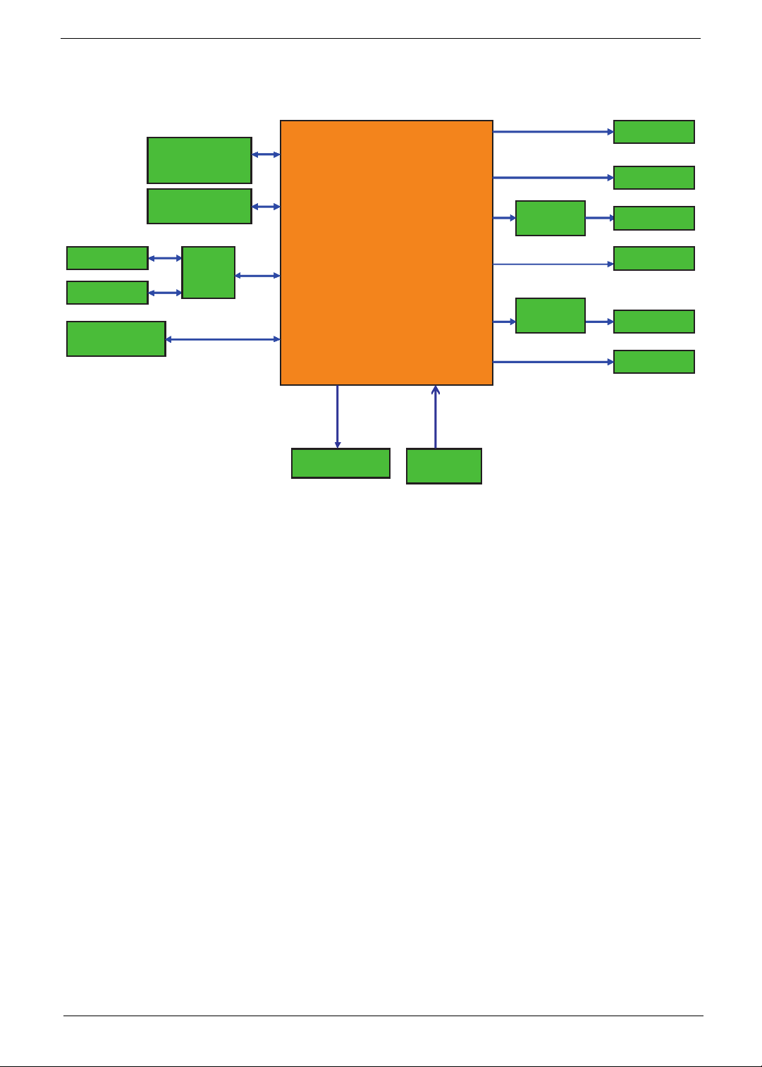
Studio MMP3400 System Block Diagram
16MB SDRAM
16MB SDRAM
(8Mx16)x1pcs
(8Mx16)x1pcs
2MB SPI Flash
2MB SPI Flash
ESS
ESS
SATA HDD
SATA HDD
Mini-USB
Mini-USB
USB port x1
USB port x1
Host mode type A
Host mode type A
GL830
GL830
IDE
IDE
ES6461
ES6461
Power/HDD LED
Power/HDD LED
IR
IR
Receiver
Receiver
Audio
Audio
filter
filter
HDMI TX
HDMI TX
ES7109
ES7109
Component
Component
Composite
Composite
Audio L/R
Audio L/R
SPDIF
SPDIF
HDMI
HDMI
Blower
Blower
Chapter 1 3
Page 12
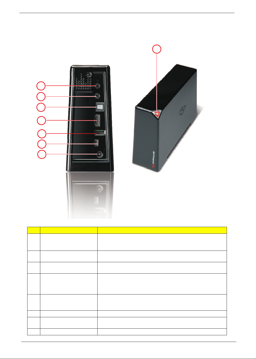
Your Studio MMP3400 tour
Appearance
2
3
4
5
6
7
8
1
# Item Description
1 Connection LIght
2 High Definition Video Out This connector provides a high definition video signal. The YPbPr cable
3 A/V Out This connector provides video and analogue audio signals. The provided
4 SPDIF This interface is used to transfer compressed digital audio and carry the
5 HDMI This connector provides a high definition audio and video signal. The HDMI
6 USB host To connect a USB key.
7 USB port Whe the Studio is connected to a computer, this port is used to transfer files
8 Power connector The AC adapter must be connected to this port.
4 Chapter 1
• Red - On
• Flashing - Hard drive activity
• Off - Standby
must be connected to this port.
cable includes S-Video, Composite video and stereo audio outputs.
signal between the output in your system to a home theater system
designed for Dolby Digital, DTS surround sound or used to inter-connect
commercial audio equipment.
cable must be connected to this port and outputs to a monitor or HDTV with
HDMI input port.
via a USB cable.
Page 13
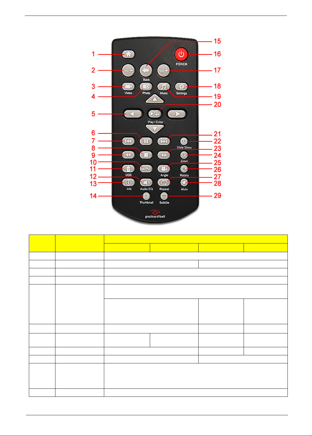
Removet Control
# Button
1 HOME Display the main menu
2 VOL - Decrease volume -
3 VIDEO Go to the Video screeen
4 PHOTO Go to the Photo screen
5 DIRECTION KEYS Go up, down, left, right.
6PAUSE
7 SKIP- Go to previous
8 STOP Stop playback Stop slideshow -
9 FAST REWIND Reverse play -
10 OUTPUT Toggle video out format. You can switch between the individual video outputs pressing
11 USB Go to the USB device that is connected to the USB port on your Studio.
Movie Music Picture Settings
Go back/forward 12 seconds during
Pause during playback
movie
this button. The video output selected at any time will be shown on the screen. If you
cannot see the correct image on a TV or VGA screen, press this button until the image
appears.
Function depends on active selection:
Left arrow: go up one directory.
Go to previous/next
playback
Go to previous song Go to previous
image. Move up/
down/left/right in
zoom mode.
Pause slideshow -
image
-
-
Chapter 1 5
Page 14
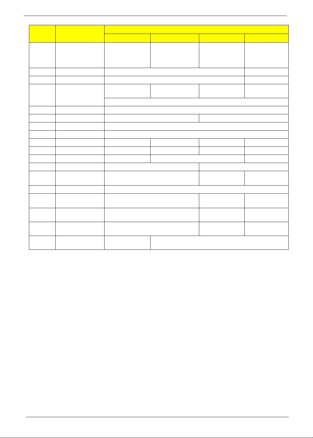
# Button
12 AUDIO/EQ Switch audio track
13 INFO Displays file information (e.g. size, format, etc.) during playback -
14 THUMBNAILS Displays image preview -
15 BACK Return to playlist
16 POWER Power On/Off
17 VOL + Increase volume
18 SETTINGS Go to the Settings screen
19 MUSIC Go to the Music screen
20 PLAY/ENTER Play a movie Play a song Display an image Select
21 SKIP + Go to next movie Go to next song Go to next image -
22 SLIDESHOW - Play all files as a slideshow -
23 FAST FORWARD Fast forward -
24 ZOOM - Zoom in/out
25 ANGLE Not used
26 ROTATE - Rotate image
27 REPEAT Repeat playback (Repeat One, Repeat All,
28 MUTE Mute the sound Mute sound during
29 SUBTITLE Toggle language
Movie Music Picture Settings
during playback
during playback
Shuffle, None)
subtitles
Function depends on active selection:
Adjust the music
playback effect
- Return to playlist
Return to the previous menu
Adjust the music
playback effect
during music
slideshow
during playback
(2x, 4x, 8x)
(90° clockwise)
Repeat slideshow -
slideshow
-
-
Return to the main
menu
-
-
-
6 Chapter 1
Page 15

Chapter 2
Machine Disassembly and Replacement
This chapter contains step-by-step procedures on how to disassemble and reassemble the Studio MMP3400
for maintenance and troubleshooting.
Disassembly/Reassembly Requirements
To disassemble or reassemble the computer, you need the following tools:
• Wrist grounding strap and conductive mat for preventing electrostatic discharge
• Philips screwdriver (may require different size)
• Tweezers
NOTE: The screws for the different components vary in size. During the disassembly process, group the
screws with the corresponding components to avoid mismatch when putting back the components.
Pre-disassembly Instructions
Before proceeding with the disassembly procedure, make sure that you do the following:
1. Turn off the power to the system and all peripherals.
2. Unplug the AC adapter and all power and signal cables from the system.
3. Place the system on a flat, stable surface.
Chapter 2 7
Page 16

Disassembly Process
This section guide you on how to disassemble the Studio MMP3400 when you need to perform system service
of to replace a replaceable parts.
The list below are the list of screws used in the Studio MMP3400.
Main Screw List
Item Color Tor que Part No.
A Black 4.5kgf-cm 86.SA33Q.8R0
B Silver 6.0kgf-cm 86.9A532.6R0
C Silver 1.5kgf-cm 86.9A552.5R0
D Silver 6.0kgf-cm 86.5A534.4R0
Removing the Outer Casing
1. Remove the rubber foot near the front of the system.
2. Remove the screws (A) from where the rubber foot was and at the back of the system.
Step (Quantity) Color Tor que
1~2 2 Black 4.5 kgf-cm
8 Chapter 2
Page 17

3. Carefully release the latches and carefully lift up the outer casing.
Removing the Base
1. See “Removing the Outer Casing” on page 8.
2. Remove the one screw (B) securing the base to the housing.
Step (Quantity) Color Tor que
1 1 Silver 6.0 kgf-cm
Chapter 2 9
Page 18

3. Release the latches and carefully lift up the housing.
Removing the Hard Drive
1. See “Removing the Outer Casing” on page 8.
2. See “Removing the Base” on page 9.
3. Carefully slide out the metal shielding.
4. Remove the three screws (B) securing the hard drive to the housing.
10 Chapter 2
Page 19

Step (Quantity) Color Tor que
1~3 3 Silver 6.0 kgf-cm
5. Slide out the hard drive and remove it from the housing.
NOTE: To prevent damage to device, avoid pressing down on it or placing heavy objects on top of it.
Removing the Fan Module
1. See “Removing the Outer Casing” on page 8.
2. See “Removing the Base” on page 9.
3. See “Removing the Hard Drive” on page 10.
4. Disconnect the fan cable from CN4 on the main board.
Chapter 2 11
Page 20

5. Remove the three screws (C) securing the fan module to the housing.
Step (Quantity) Color Tor que
1~3 3 Silver 1.5 kgf-cm
6. Remove the fan module from the housing.
12 Chapter 2
Page 21

Removing the IR Board
1. See “Removing the Outer Casing” on page 8.
2. See “Removing the Base” on page 9.
3. See “Removing the Hard Drive” on page 10.
4. See “Removing the Fan Module” on page 11.
5. Disconnect the IR cable from the IR board connector.
6. Remove the one screw (C) securing the LED bracket.
Step (Quantity) Color Tor que
1 1 Silver 1.5 kgf-cm
7. Remove the LED bracket.
Chapter 2 13
Page 22

8. Remove the one screw (C) securing the IR board to the housing.
Step (Quantity) Color Tor que
1 1 Silver 1.5 kgf-cm
9. Remove the IR board from the housing.
Removing the Main Board
1. See “Removing the Outer Casing” on page 8.
2. See “Removing the Base” on page 9.
3. See “Removing the Hard Drive” on page 10.
4. See “Removing the Fan Module” on page 11.
5. See “Removing the IR Board” on page 13.
6. Remove the four screws (B) securing the main board to the housing.
Step (Quantity) Color Tor que
1~4 4 Silver 6.0 kgf-cm
14 Chapter 2
Page 23

7. Remove the one screw (D) near the HDMI connector.
Step (Quantity) Color Tor que
1 1 Silver 6.0 kgf-cm
8. Carefully lift up and remove the main board from the housing.
Note: Circuit board >10 cm² has been highlighted with the yellow rectangle as above image shows.
Please detach the Circuit boards and follow local regulations for disposal.
9. Disconnect the IR cable from the main board.
Chapter 2 15
Page 24

Reassembly Process
This section guide you on how to reassemble the Studio MMP3400 after maintenance and troubleshooting.
Main Board Reassembly
1. Reconnect the IR cable into the main board.
2. Replace the main board into the housing.
3. Replace the one screw (D) near the HDMI connector.
Step (Quantity) Color Tor que
1 1 Silver 6.0 kgf-cm
16 Chapter 2
Page 25

4. Replace main board and secure it to the housing with the four screws (B).
Step (Quantity) Color Tor que
1~4 4 Silver 6.0 kgf-cm
IR Board Reassembly
1. See “Main Board Reassembly” on page 16.
2. Replace the IR board and secure it to the housing with the one screw (C).
Step (Quantity) Color Tor que
1 1 Silver 1.5 kgf-cm
Chapter 2 17
Page 26

3. Replace the LED bracket and secure it to the housing with the one screw (C).
Step (Quantity) Color Tor que
1 1 Silver 1.5 kgf-cm
4. Reconnect the IR cable into the IR board connector CN1.
Fan Module Reassembly
1. See “Main Board Reassembly” on page 16.
2. See “IR Board Reassembly” on page 17.
18 Chapter 2
Page 27

3. Replace the fan module and secure it to the housing with the three screws (C).
Step (Quantity) Color Tor que
1~3 3 Silver 1.5 kgf-cm
4. Reconnect the fan module cable to the connector CN4 on the main board.
Chapter 2 19
Page 28

Hard Drive Reassembly
1. See “Main Board Reassembly” on page 16.
2. See “IR Board Reassembly” on page 17.
3. See “Fan Module Reassembly” on page 18.
4. Slide the hard drive until the connector on the hard drive is securely connected to the SATA connector on
the main board.
5. Secure the hard drive to the housing with the three screws (B).
Step (Quantity) Color Tor que
1~3 3 Silver 6.0 kgf-cm
20 Chapter 2
Page 29

6. Replace the metal shielding to the hard drive.
Base Reassembly
1. See “Main Board Reassembly” on page 16.
2. See “IR Board Reassembly” on page 17.
3. See “Fan Module Reassembly” on page 18.
4. See “Hard Drive Reassembly” on page 20.
5. Replace the housing into the base until the latches clicks into place.
Chapter 2 21
Page 30

6. Secure the housing with the one screw (B).
Step (Quantity) Color Tor que
1 1 Silver 6.0 kgf-cm
Outer Casing Reassembly
1. See “Main Board Reassembly” on page 16.
2. See “IR Board Reassembly” on page 17.
3. See “Fan Module Reassembly” on page 18.
4. See “Hard Drive Reassembly” on page 20.
5. See “Base Reassembly” on page 21.
6. Carefully slide down the outer casing into the housing until the latches clicks into place.
22 Chapter 2
Page 31

7. Secure the outer casing to the housing with the two screws (A).
Step (Quantity) Color Tor que
1~2 2 Black 4.5 kgf-cm
8. Replace the rubber foot to cover one of the screw.
Chapter 2 23
Page 32

24 Chapter 2
Page 33

Chapter 3
Troubleshooting
This is a list of possible situations that may arise during the use of your Studio MMP3400, and it gives easy
answers and solutions to these questions.
No display on TV
• Make sure the Studio is plugged in and turned on.
• Check whether the TV is powered on and the TV video is in AV mode.
• Make sure that the AV cable is correctly connected to the Studio.
• Please press the OUTPUT button to switch the Studio display mode.
• Make sure the user’s TV/Monitor supports PAL/50MHz.
No sound or poor sound quality
• Make sure that the audio cable is correctly connected to the Studio.
• Check whether the Studio is in mute mode and/or volume decreased to minimum.
No picture or poor picture quality
• Make sure that the video cable is correctly connected to the Studio.
• Make sure that the video mode is set correctly.
Not recognised by computer
• Check whether the USB cable is correctly connected to the machine; make sure that the Studio is
attached correctly.
• Check that the AC adapter is plugged in and connected correctly.
• Check whether the Studio is on.
The remote control does not work well
• Check whether the battery is inserted correctly and whether or not the battery is out of power.
• The distance between the Studio and control should not be too far.
Subtitles are not displayed when watching a DivX movie
• The Studio can read .srt, .sub and .smi subtitle files. Other subtitle files will not be displayed.
• The subtitle file must have the same name and be in the same directory as the movie file. I.e
"movie.avi" and "movie.srt".
• The subtitle file must be in Unicode format. To check this, open the .sub or .srt file with notepad,
select "Save As" and choose the Unicode option from the encoding combo box.
No SPDIF audio out
• Check the “SETTINGS” -> “AUDIO OUTPUT” is set “SPDIF/SAW” or “SPDIF/PCM”
Chapter 3 25
Page 34

How to upgrade firmware
1. Put the firmware into the USB flash drive and plug this USB flash drive into MMP3400.
2. Power on MMP3400 and go to SETTINGS menu.
26 Chapter 3
Page 35

3. In the SETTINGS menu, select PREFERENCES and use navigation key to highlight Firmware Upgrade.
Then press RIGHT key to highlight UPGRADE and press ENTER.
4. System will pop out a confirmation message. Press LETF key to highlight YES in red and then press
ENTER.
Chapter 3 27
Page 36

5. System will start to update the firmware. After the system completes the upgrade, it will power on
automatically.
6. Press POWER key on the remote control to power on the system.
7. After the system is boot up, go to “SETTINGS-->PREFERENCES. Use the navigation key to highlight
Default. Press RIGHT key to highlight RESET and then press ENTER key to process factory reset. This
completes firmware upgrade.
28 Chapter 3
Page 37

Connector Locations and Board Layout
Main Board Layout
CN5
Chapter 4
U7
CN4
U17
JK3JK2
U6
U5
U18
U9
SKT1SKT5
SKT2
SKT4
U19
U10
U11
SKT3 JK1
Item Description Item Description
U5 Processor ES6461SAB JK2 component video
U6 SDRAM NT5SV8M16FS-6K JK3 composite video+ audio L/R
U7 Flash MX25L1605DM SKT1 HDMI connctor
U9 Scaler ES7109S SKT3 Mini-USB connector
U10 Controller GL830-MX SKT4 USB A Type
U11 EEPROM AT93C46DN SKT5 SPDIF optical connector
U17 Audio amplifer MC4558C SKT2 SATA connector
U18 EEPROM AT24C02BN CN4 Fan connector
U19 Flash SST39VF010 CN5 IR board connector
JK1 12V DC Jack
Chapter 4 27
Page 38

Rear I/O Connectors
Composite Jack
Audio R/L
Component Jack
IR Board Placement
SPDIF
HDMI
USB A Type
DC Jack
Mini USB
28 Chapter 4
Page 39

Chapter 5
FRU (Field Replaceable Unit) List
This chapter gives you the FRU (Field Replaceable Unit) listing in global configurations of Studio MMP3400.
Refer to this chapter whenever ordering for parts to repair or for RMA (Return Merchandise Authorization).
Please note that WHEN ORDERING FRU PARTS, you should check the most up-to-date information available
on your regional web or channel. For whatever reasons a part number change is made, it will not be noted on
the printed Service Guide. For ACER AUTHORIZED SERVICE PROVIDERS, your Acer office may have a
DIFFERENT part number code from those given in the FRU list of this printed Service Guide. You MUST use
the local FRU list provided by your regional Acer office to order FRU parts for repair and service of customer
machines.
To scrap or to return the defective parts, you should follow the local government ordinance or regulations on
how to dispose it properly, or follow the rules set by your regional Acer office on how to return it.
Pictures Part Name Description OEM Part No.
REMOTE CONTROLLER 2T1-32 REMOTE CONTROL 2T1-32 25.T1901.001
ADAPTER 24W 12V APD WA-24E12G-AMA
EXTERNAL MINI USB CABLE 600MM C.A MINI USB TO USB CABLE 50.T1901.002
AUDIO CABLE 1M PHONE JACK WITH
EU
IR BOARD PE661L/MMP3400 IR BOARD -1(DIP 55.T1901.001
COMPOSITE
ADP 24W 12V WA-24E12G-AMA EU AP.02409 .001
C.A PHONE JACK WITH COMPOSITE 50.T1901.003
VEDIO CABLE 1M PHONE JACK WITH
COMPONENT
C.A PHONE JACK WITH COMPONENT 50.T1901.004
Chapter 5 29
Page 40

HDMI CABLE 1.5M C.A HDMI CABLE WITH 1.5M 50.T1901.005
IR BAORD CABLE C.A. P7 C2 L170 50.T1901.001
IR/LED HOLDER HLDR LED MMP3400 42.T1901.001
TOP COVER ASSY TOP COVER MMP3400 60.T1901.002
REAR COVER ASSY BOTTOM COVER MMP3400 60.T1901.003
TOP SHIELD BRACKET BRKT TOP SHIELD MMP3400 33.T1901.001
LOWER COVER ASSY LOWER MMP3400 60.T1901.001
FAN BLOWER MMP3400 FORCECON 23.T1901.001
FAN BLOWER MMP3400 SUNON 23.T1901.001
30 Chapter 5
Page 41

HDD 2TB 3.5” 5400RPM SATA WD GP500M
WD20EADS-22R6B0 GP
HDD 3.5” 1000GB 7200RPM SATA
SEAGATE SEAGATE ST31000528AS LF
HDD 1TB 3.5” 7200RPM SATA HGST
SATURN HDT721010SLA360
HDD 1TB 3.5” 5400RPM SATAII WD10EADS-
HDD 1.5TB 3.5” 7200RPM SATA SEAGATE
HDD 320GB 3.5” 7200RPM SATA II 8MB
HDD 3.5” 500GB 7200RPM SATA SEAGATE
HDD 500GB 3.5” 7200RPM 8MB SATA HGST
HDD 750GB HGST 3.5” 7200RPM SATURN
22M4B0 8MB GP
BRINKS ST31500341AS 32MB CC4H 7
HDD 320GB 3.5” 7200RPM SATA II
SEAGATE PHARAOH 8MB NCQ
HGST HDT721032SLA380 SATURN
PHARAOH ST3500418AS
HDT721050SLA360
HDD 3.5” 500GB 7200RPM SATA WD
XL320M WD5000AAKS-22M9A0
HDD 640GB 3.5” 7200RPM HGST
HDT721064SLA360 SATURN SATA
HDD 750GB 3.5” 7200RPM SATA II
SEAGATE PHARAOH ST3750528AS
SATA HDT721075SLA360
HDD 2TB WD WD20EADS-22R6B0 GP KH.02K08.001
HDD 1TB SGT ST31000528AS 7.2KR KH.01K01.007
HDD 1TB HGST HDT721010SLA360 KH.01K07.002
HDD 1TB WD10EADS-22M2B0 GP KH.01K08.005
HDD 1.5TB SGT ST31500341AS 7.2 KH.15K01.002
HDD 320G 3.5” SEAGATE PHARAOH KH.32001.015
HDD 320GB HGST HDT721032SLA380 KH.32007.006
HDD 500GB SGT ST3500418AS 7.2K KH.50001.012
HDD 500GB HGST HDT721050SLA360 KH.50007.008
HDD 500GB WD WD5000AAKS-22M9A0 KH.50008.014
HDD 640GB HGST HDT721064SLA360 KH.64007.001
HDD 750GB SGT ST3750528AS 7.2K KH.75001.008
HDD 750GB HGST HDT721075SLA360 KH.75007.002
MAINBOARD ESS6461 SAB ES7109 FOR
SCREW MACH WAFER NYLOK COARSE
MMP3400
FOOT RUBBER RUB FOOT MMP3400 47.T1901.001
M2*L5 NI
SCREW FLAT M3*L4 NI SCRW FLAT M3*L4 NI 86.5A534.4R0
SCREW M2.6X8 SCRW M2.6X8 86.SA33Q.8R0
SCREW WAFER #6-32 L6 NI SCREW WAFER #6-32 L6 NI 86.9A532.6R0
PE661L/MMP3400 MB -1 DIP MB.T1901.001
SCREW MACH WAFER M2*L5 NI 86.9A552.5R0
Chapter 5 31
Page 42

32 Chapter 5
Page 43

A
appearance 4
B
block diagram 3
D
disassembly process 8
Disassembly Requirements 7
F
Features 1
field replaceable unit list 29
I
ir board placement 28
Index
M
main board layout 27
Main screw list 8
R
rear i/o connectors 28
reassembly process 16
remote control 5
S
System
Block Diagram 3
System block diagram
UMA 3
T
Troubleshooting 25
V
view
left 5
33
Page 44

34
 Loading...