

Page 1

M9N System
User’s Guide
Page 2

Copyright
Copyright 1997 by this company. All rights reserved. No part of
this publication may be reproduced, transmitted, transcribed, stored in
a retrieval system, or translated into any language or computer
language, in any form or by any means, electronic, mechanical,
magnetic, optical, chemical, manual or otherwise, without the prior
written permission of this company.
Disclaimer
This company makes no representations or warranties, either
expressed or implied, with respect to the contents hereof and
specifically disclaims any warranties, merchantability or fitness for
any particular purpose. Any software described in this manual is sold
or licensed "as is". Should the programs prove defective following
their purchase, the buyer (and not this company, its distributor, or its
dealer) assumes the entire cost of all necessary servicing, repair, and
any incidental or consequential damages resulting from any defect in
the software. Further, this company reserves the right to revise this
publication and to make changes from time to time in the contents
hereof without obligation to notify any person of such revision or
changes.
Intel is a registered trademark of Intel Corporation.
Pentium II is a trademark of Intel Corporation.
Windows, WindowsNT, Windows 95 are trademarks and/or registered trademarks of
Microsoft Corporation.
Other brand and product names are trademarks and/or registered trademarks of their
respective holders.
ii
Page 3

IMPORTANT SAFETY INSTRUCTIONS
1. Read these instructions carefully. Save these instructions for
future reference.
2. Follow all warnings and instructions marked on the product.
3. Unplug this product from the wall outlet before cleaning. Do not
use liquid cleaners or aerosol cleaners. Use a damp cloth for
cleaning.
4. Do not use this product near water.
5. Do not place this product on an unstable cart, stand, or table.
The product may fall, causing serious damage to the product.
6. Slots and openings in the cabinet and the back or bottom are
provided for ventilation; to ensure reliable operation of the
product and to protect it from overheating, these openings must
not be blocked or covered. The openings should never be
blocked by placing the product on a bed, sofa, rug, or other
similar surface. This product should never be placed near or
over a radiator or heat register, or in a built-in installation unless
proper ventilation is provided.
7. This product should be operated from the type of power indicated
on the marking label. If you are not sure of the type of power
available, consult your dealer or local power company.
8. This product is equipped with a 3-wire grounding-type plug, a
plug having a third (grounding) pin. This plug will only fit into a
grounding-type power outlet. This is a safety feature. If you are
unable to insert the plug into the outlet, contact your electrician
to replace your obsolete outlet. Do not defeat the purpose of the
grounding-type plug.
9. Do not allow anything to rest on the power cord. Do not locate
this product where persons will walk on the cord.
iii
Page 4

10. If an extension cord is used with this product, make sure that the
total ampere rating of the equipment plugged into the extension
cord does not exceed the extension cord ampere rating. Also,
make sure that the total rating of all products plugged into the
wall outlet does not exceed 15 amperes.
11. Never push objects of any kind into this product through cabinet
slots as they may touch dangerous voltage points or short out
parts that could result in a fire or electric shock. Never spill
liquid of any kind on the product.
12. Do not attempt to service this product yourself, as opening or
removing covers may expose you to dangerous voltage points or
other risks. Refer all servicing to qualified service personnel.
13. Unplug this product from the wall outlet and refer servicing to
qualified service personnel under the following conditions:
a. When the power cord or plug is damaged or frayed
b. If liquid has been spilled into the product
c. If the product has been exposed to rain or water
d. If the product does not operate normally when the operating
instructions are followed. Adjust only those controls that are
covered by the operating instructions since improper
adjustment of other controls may result in damage and will
often require extensive work by a qualified technician to
restore the product to normal condition.
e. If the product has been dropped or the cabinet has been
damaged
f. If the product exhibits a distinct change in performance,
indicating a need for service
iv
Page 5

14. Replace battery with the same type as the product's battery we
recommend. Use of another battery may present a risk of fire or
explosion. Refer battery replacement to a qualified serviceman.
15. Warning! Battery may explode if not handled properly. Do not
recharge, disassemble or dispose of in fire. Keep away from
children and dispose of used battery promptly.
16. Use only the proper type of power supply cord set (provided in
your keyboard/manual accessories box) for this unit. It should be
a detachable type: UL listed/CSA certified, type SVT/SJT, rated
6A 125V minimum, VDE approved or its equivalent. Maximum
length is 15 feet (4.6 meters).
v
Page 6

CD-ROM Safety Warning
DANGER
INVISIBLE RADIATION WHEN OPEN.
AVOID EXPOSURE TO BEAM.
VORSICHT
UNSICHTBARE LASERSTRAHLUNG WENN GEÖFFNET.
NICHT IN DEN STRAHL SEHEN.
ATTENTION
RADIATION DU FAISCEAU LASER INVISIBLE. EN CAS
D’OUVERTURE. EVITER TOUTE EXPOSITION AUX RAYONS.
VARO
AVATTAESSA OLET ALTTIINA NÄKYMÄTTÖMÄLLE
LASERSÄTEILYLLE ÄLÄ KATSO SÄTEESEEN.
VARNING!
OSYNLING LASERSTRÄLNING NÄR DENNA DEL ÄR ÖPPNAD.
BETRAKTA EJ STRÄLEN.
VARNING
OSYNLING LASERSTRÄLNING NÄR DENNA DEL ÄR ÖPPNAD.
STIRRA EJ IN I STRÄLEN.
ADVARSEL
LASERSTRÄLING VED ÄBNING. SE IKKE IND I STRÄLEN.
CLASS 1 LASER PRODUCT
APPAREIL A LASER DE CLASSE 1
LASER KLASSE 1
LOUKAN 1 LASERLAITE
PRODUIT LASER
CATEGORIE 1
vi
Page 7

Caution on Lithium Batteries
CAUTION
Danger of explosion if battery is incorrectly replaced. Replace only
with the same or equivalent type recommended by the manufacturer.
Discard used batteries according to the manufacturer’s instructions.
ADVARSEL!
Lithiumbatteri - Eksplosionsfare ved fejlagtig håndtering.
Udskiftning må kun ske med batteri af samme fabrikat og type.
Léver det brugte batteri tilbage til leverandøren.
ADVARSEL
Eksplosjonsfare ved feilaktig skifte av batteri.
Benytt samme batteritype eller en tilsvarende
type anbefalt av apparatfabrikanten.
Brukte batterier kasseres i henhold til fabrikantens instruksjoner.
VARNING
Explosionsfara vid felaktigt batteribyte.
Anvãnd samma batterityp eller en ekvivalent typ som
rekommenderas av apparattillverkaren.
Kassera anvãnt batteri enligt fabrikantens instruktion.
VAROITUS
Päristo voi räjähtää, jos se on virheellisesti asennettu.
Vaihda paristo ainoastaan laitevalmistajan suosittelemaan tyyppiin.
Hävitä käytetty paristo valmistajan ohjeiden mukaisesti.
VORSICHT!
Explosionsgefahr bei unsachgemäßen Austausch der Batterie Ersatz
nur durch denselben oder einem vom Hersteller empfohlenem
ähnlichen Typ. Entsorgung gebrauchter Batterien nach Angaben des
Herstellers.
vii
Page 8

FCC Class A Radio Frequency Interference
Statement
WARNING!
This equipment has been tested and found to comply with the limits
for a Class A digital device, pursuant to Part 15 of FCC Rules. These
limits are designed to provide reasonable protection against harmful
interference when the equipment is operated in a commercial
environment. This equipment generates, uses, and can radiate radio
frequency energy and, if not installed and used in accordance with the
instruction manual, may cause harmful interference to radio
communications. Operation of this equipment in a residential area is
likely to cause harmful interference in which case the user will be
required to correct the interference at his own expense.
Notice 1:
The changes or modifications not expressly approved by the party
responsible for compliance could void the user's authority to operate
the equipment.
Notice 2:
If the EUT was tested with special shielded cables, the operator’s
manual for such product shall also contain the following statement or
their equivalent:
Shielded interface cables and/or AC power cord, if any, must be used
in order to comply with the emission limits.
viii
Page 9

About this Manual
Purpose
This user’s guide aims to give you all the information you need to
operate the system properly.
Manual Structure
This user’s guide consists of five chapters.
Chapter 1 System Board
This chapter describes the system board and all its major
components. It contains the system board layout, jumper
settings, and information on other internal devices.
Chapter 2 CPU Board
This chapter describes the dual-processor CPU board. It
includes the CPU board jumper settings and cache and system
memory configurations. Step-by-step instructions tell you how
to install the CPUs and memory modules.
Chapter 3 BIOS Utility
This chapter discusses the system BIOS and tells how to
configure the system by setting the BIOS parameters.
Chapter 4 LAN Information
This chapter gives valuable information on LAN drivers.
Chapter 5 System Utilities
This chapter tells how to use the AFlash BIOS Utility and the
SCSISelect Configuration Utility.
ix
Page 10

Conventions
The following are the conventions used in this manual:
Text entered by user Represents text input by the user.
Screen messages
, , , etc. Represent the actual keys that you
Denotes actual messages that
appear on the screen.
have to press on the keyboard.
NOTE
Gives bits and pieces of additional
information related to the current
topic.
WARNING
Alerts you to any damage that
might result from doing or not
doing specific actions.
CAUTION
Gives precautionary measures to
avoid possible hardware or
software problems.
IMPORTANT
Reminds you to do specific actions
relevant to the accomplishment of
procedures.
TIP
Tells how to accomplish a
procedure through little shortcuts.
x
Page 11

Table of Contents
Chapter 1 System Board
1.1 Features .................................................................. 1-1
1.2 Major Components ...................................................1-2
1.3 Layout......................................................................1-3
1.4 Jumpers and Connectors .........................................1-4
1.4.1 Jumper and Connector Locations..............1-4
1.4.2 Jumper Settings........................................1-5
1.4.3 Connector Functions..................................1-6
1.5 ESD Precautions......................................................1-7
1.6 Video Memory Upgrade ...........................................1-8
1.7 ASM Pro..................................................................1-9
1.8 Remote Diagnostic Management ...........................1-10
1.8.1 Installing the RDM Module....................... 1-10
1.9 Error Messages......................................................1-11
1.9.1 Software Error Messages.........................1-11
1.9.2 System Error Messages........................... 1-11
1.9.3 Correcting Error Conditions.....................1-14
xi
Page 12

Chapter 2 CPU Board
2.1 Layout......................................................................2-2
2.2 Jumper Locations ....................................................2-2
2.3 Jumper Settings .......................................................2-3
2.4 Memory Upgrade.....................................................2-4
2.4.1 Memory Configurations.............................2-4
2.4.2 Installing a DIMM......................................2-5
2.4.3 Removing a DIMM....................................2-6
2.4.3 Reconfiguring the System.........................2-7
2.5 Installing the Processor Heat Sink and Fan..............2-8
2.6 Installing a Pentium II Processor............................2-11
2.7 Removing a Pentium II Processor ..........................2-13
2.8 CPU Board Installation...........................................2-14
Chapter 3 BIOS Utility
3.1 Entering Setup.........................................................3-2
3.2 Basic System Configuration.....................................3-3
xii
3.2.1 Date and Time ..........................................3-4
3.2.2 Diskette Drives..........................................3-5
3.2.3 Onboard IDE.............................................3-6
3.2.4 IDE Drives.................................................3-6
3.2.5 Total Memory ............................................3-8
3.2.6 Enhanced IDE Features............................3-8
3.2.7 Num Lock After Boot.................................3-9
3.2.8 Memory Test.............................................3-9
3.2.9 Quiet Boot.................................................3-9
3.2.10 Configuration Table.................................3-10
Page 13

3.3 Advanced System Configuration............................3-11
3.3.1 Internal Cache (CPU Cache)...................3-11
3.3.2 External Cache (CPU Cache)..................3-12
3.3.3 ECC/Parity Mode Selection.....................3-12
3.3.4 Operation of ECC ....................................3-13
3.3.5 Memory at 15MB-16MB...........................3-13
3.4 PCI System Configuration......................................3-14
3.4.1 PCI IRQ Setting....................................... 3-15
3.4.2 VGA Palette Snoop.................................3-16
3.4.3 Onboard LAN..........................................3-16
3.4.4 USB Host Controller................................3-17
3.4.5 Onboard SCSI1.......................................3-17
3.4.6 Onboard SCSI2.......................................3-17
3.4.7 PCI IRQ Sharing......................................3-17
3.4.8 Plug & Play OS.......................................3-18
3.4.9 Reset Resources Assignment..................3-18
3.5 Power Saving Configuration ...................................3-19
3.5.1 Power Management Mode.......................3-20
3.5.2 Monitored Activities.................................3-21
3.6 System Security.....................................................3-22
3.6.1 Disk Drive Control...................................3-22
3.6.2 Onboard Communication Ports................ 3-24
3.6.3 Onboard PS/2 Mouse (IRQ12).................3-26
3.6.4 Setup Password.......................................3-27
3.6.5 Power On Password................................3-29
3.7 Load Setup Default Settings...................................3-30
3.8 Leaving Setup ........................................................3-31
xiii
Page 14

Chapter 4 LAN Information
4.1 DOS and Windows 3.1 Setup for Novell
NetWare Clients ......................................................4-2
4.1.1 Automatic configuration.............................4-2
4.1.2 Test the adapter and install network
drivers.......................................................4-2
4.1.3 Test the adapter with a responder on
the network (optional)................................4-3
4.1.4 Troubleshooting......................................... 4-4
4.2 Windows NT - Server or Workstation.......................4-5
4.2.1 Automatic configuration.............................4-5
4.2.2 Install network drivers and test the
adapter......................................................4-5
4.2.3 Troubleshooting......................................... 4-6
4.3 Windows 95.............................................................4-8
4.3.1 Automatic Configuration ............................4-8
4.3.2 Adapter installation for Windows 95........... 4-8
4.3.3 Install PROSet Software and
Test the Adapter........................................4-9
4.3.4 Manually Adding an Adapter....................4-10
4.3.5 Troubleshooting.......................................4-10
4.4 Other Operating Systems and Servers ...................4-11
4.5 Installing Multiple Adapters....................................4-12
4.6 Select Duplex Mode (optional)...............................4-13
4.6.1 Configuring for full duplex.......................4-13
Chapter 5 System Utilities
5.1 AFlash BIOS Utility..................................................5-1
5.1.1 Executing AFlash......................................5-2
xiv
Page 15

5.1.2 Quick Way to Execute AFlash...................5-3
5.2 SCSISelect Configuration Utility ...............................5-4
5.2.1 Overview...................................................5-4
5.2.2 Utility Options............................................5-6
5.2.3 Configuring Multiple SCSI Controllers......5-20
5.2.4 Disk Drives Over 1 GByte .......................5-21
xv
Page 16

List of Figures
1-1 System Board Layout...............................................1-3
1-2 System Board Jumper and Connector Locations......1-4
1-3 Installing a Video Memory Chip................................1-8
1-4 Installing the RDM Module.....................................1-10
2-1 CPU Board Layout...................................................2-2
2-2 Pentium II CPU Board Jumper Locations.................2-2
2-3 Installing a DIMM.....................................................2-5
2-4 Removing a DIMM...................................................2-6
2-5 Matching the Fan-Heat Sink Clips with the Holes
on the Processor ......................................................2-8
2-6 Inserting the Clip Ends to the Processor Holes.........2-9
2-7 Locking a Wide Clip End........................................2-10
2-8 Locking a Narrow Clip End.....................................2-10
2-9 Installing the Pentium II Retention Mechanism.......2-11
2-10 Installing a Pentium II Processor............................2-12
2-11 Securing the Pentium II Processor.........................2-12
2-12 Unlocking the Module Latches................................2-13
2-13 Removing the Pentium II Processor.......................2-13
2-14 Installing the CPU Board........................................2-14
5-1 Options Menu Screen...............................................5-6
5-2 Configure/View Host Adapter Settings Screen..........5-7
5-3 Host Adapter SCSI ID Selections.............................5-8
5-4 SCSI Parity Checking Selections .............................5-9
5-5 Host Adapter SCSI Termination.............................5-10
xvi
Page 17

List of Figures (continued)
5-6 Boot Device Configuration......................................5-11
5-7 SCSI Device Configuration.....................................5-12
5-8 Advanced Configuration Options............................5-15
5-9 SCSI Disk Utilities Screen......................................5-18
List of Tables
1-1 System Board Jumper Settings...................................5
1-2 Connector Functions ...................................................6
1-3 System Error Messages ............................................12
2-1 Settings for CPU Core/Bus Frequency Ratio
(JP1)........................................................................2-3
2-2 ITP Debug Port (JP2)...............................................2-3
2-3 Clock Settings (JP5).................................................2-3
2-4 Memory Configurations............................................2-4
3-1 Drive Control Settings............................................3-23
3-2 Serial Port 1 Settings .............................................3-24
3-3 Serial Port 2 Settings .............................................3-24
3-4 Parallel Port Settings..............................................3-25
3-5 Parallel Port Operation Mode Settings....................3-26
5-1 Settings for the SCSI Controller and All Devices......5-4
5-2 Individual Settings for SCSI Drives ..........................5-5
xvii
Page 18

Chapter
11
System Board
1.1 Features
The M9N is a dual-processor system board that supports the Intel
Pentium II CPU. It contains an exclusive connector for the CPU
board that carries two slots for the Pentium II CPU modules.
This high-performance 64-bit system board utilizes both the ISA and
the PCI local bus architecture. Two ISA and five PCI bus slots reside
on the board to allow installation of either master or slave devices.
A 50-pin Fast SCSI-II interface and two 68-pin Wide SCSI interfaces
come with the system board to connect SCSI devices. External I/O
interfaces include a parallel port and a video port, RJ-45 and USB
connectors, and keyboard and mouse ports.
The system board supports two optional features, the ASM Pro and
the remote diagnostic management (RDM), that allow better server
management. The ASM Pro detects problems in CPU thermal
condition, CPU working voltage detection (±12V/±5V/3.3V/1.5V), and
PCI bus utilization calculation. It also detects if the CPU fan or the
chassis fan malfunctions. The RDM allows execution of the RDM
diagnostic program from a remote RDM station to fix detected
problems or to reboot the system.
System Board 1-1
Page 19

1.2 Major Components
The system board has the following major components:
• CPU board slot
• Two ISA and five PCI bus slots (one PCI slot may include an
optional RAID port)
• 256-KB Flash ROM for system BIOS
• System clock/calendar with battery backup
• 50-pin Fast SCSI-II and two 68-pin Wide SCSI interfaces
• Two 24-pin RDM interfaces
• IDE hard disk and diskette drive interfaces
• Onboard VRAM and VRAM sockets for video memory upgrade
• Power connector for both standard 420-watt SPS and redundant
420-watt SPS
• Super I/O, SCSI, VGA, memory, and Advanced Server
Management (ASM) controller chipsets
• External ports:
• PS/2-compatible keyboard port (optional AT-keyboard port)
• PS/2-compatible mouse port
• Parallel port
• Video port
• RJ-45 connector
• Universal Serial Bus (USB) connector
1-2 User’s Guide
Page 20
1.3 Layout
3
5
1
2
7
8
91918
172122
1514121310
16
4
6
20
11
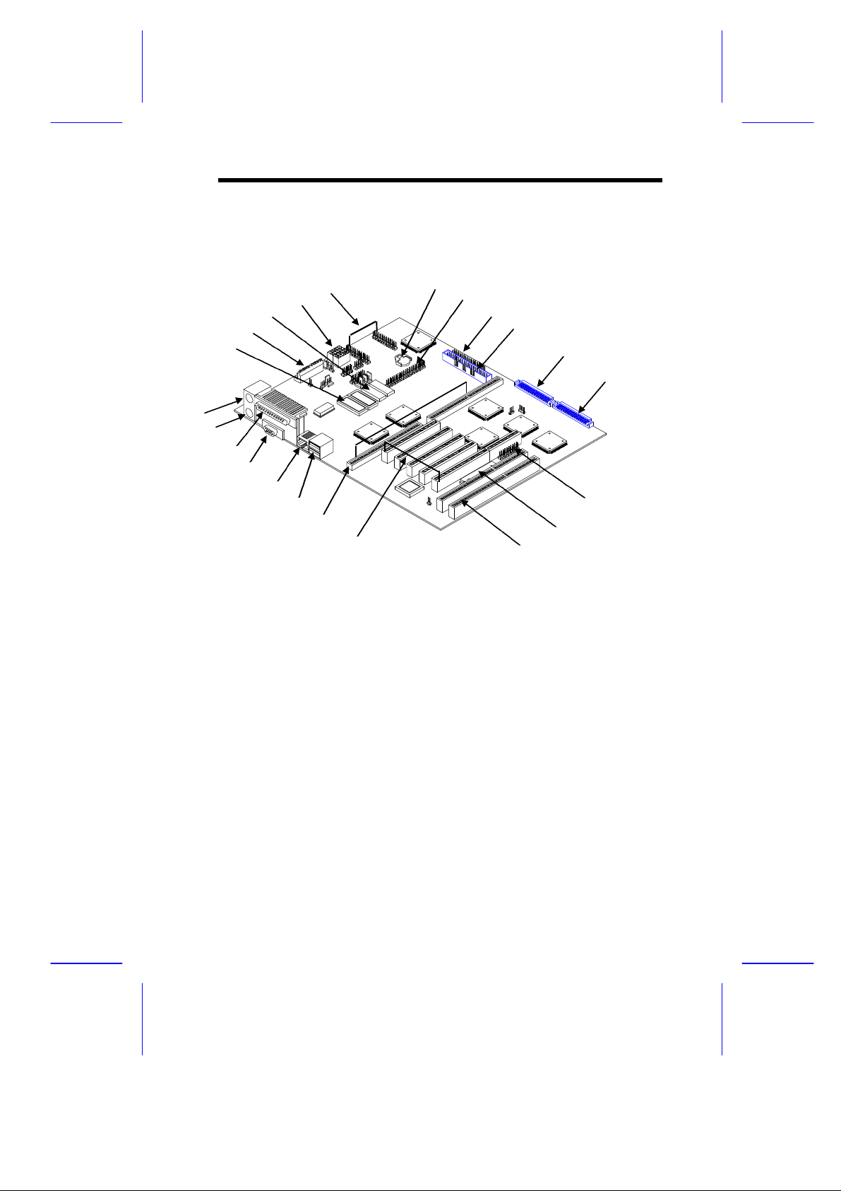
Figure 1-1 shows the system board components.
1 Keyboard port
2 Mouse port
3 Parallel port
4 Video port
5 RJ-45 connector
6 USB connector
7 CPU board slot
8 PCI slots
9 ISA slots
10 Flash ROM BIOS
11 RAID port (optional)
12 Wide SCSI connector 2
13 Wide SCSI connector 1
14 Narrow SCSI connector
15 Diskette drive connector
16 EIDE connector
17 Battery
18 RDM connectors
19 Power connectors
20 Video RAM
21 Power connector
22 Video RAM upgrade sockets
Figure 1-1 System Board Layout
System Board 1-3
Page 21
1.4 Jumpers and Connectors
1.4.1 Jumper and Connector Locations
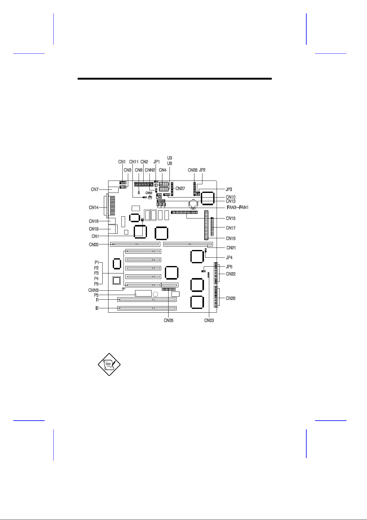
Figure 1-2 shows the jumper and connector locations on the system
board.
Figure 1-2 System Board Jumper and Connector Locations
Jumpers are prefixed “JP”. Connectors are
prefixed “CN”. The blackened pin of a
jumper represents pin 1.
1-4 User’s Guide
Page 22

1.4.2 Jumper Settings
Table 1-1 lists the system board jumpers with their corresponding
settings and functions.
Table 1-1 System Board Jumper Settings
Jumper Setting Function
Software Shutdown
Control for CN4
JP1 1-2
BIOS Type
JP2 1-2
Password Security
JP3 1-2
SCSI Channel 1
High-Byte Termination
JP4 1-2*
VGA Feature
JP5 1-2*
*
2-3
2-3*
2-3*
2-3
Open
2-3
Enabled
Disabled
Branded
Generic
Check password
Bypass password
Terminator always set to ON
SCSI terminator set to ON or OFF
by software
Terminator set to OFF
Normal (Auto)
Onboard VGA always disabled
*
Default setting
System Board 1-5
Page 23

1.4.3 Connector Functions
Table 1-2 lists the different connectors on the system board and their
respective functions.
Table 1-2 Connector Functions
Connector Function
CN1 COM 1
CN2, U3, U8 Power connectors
CN3 COM 2
CN4 Software shutdown connector for 420-watt SPS
CN7 PS/2 mouse (above) / keyboard (below) connectors
CN8 Power switch
CN9 Power LED and keylock connector
CN10 Monitor signal connector for redundant power supply
CN12 Software shutdown connector for redundant power
CN13 Backplane board LED connector
CN14 Printer port (above) / video port (below)
CN15 IDE connector
CN16 LAN connector
CN17 Diskette drive connector
CN18 Channel 1 narrow SCSI connector
CN19 Universal serial bus (USB) ports
CN22 Channel 1 wide SCSI connector
CN23 Hard disk LED connector
CN25 SMM connector
CN26 Channel 2 wide SCSI connector
CN27, CN28 RDM connectors
CNN3 Connector for chassis intrusion prevention
FA1, FA2, FA3 Fan connectors
supply
1-6 User’s Guide
Page 24

1.5 ESD Precautions
Always observe the following electrostatic discharge (ESD)
precautions before installing a system component:
1. Do not remove a component from its antistatic packaging until
you are ready to install it.
2. Wear a wrist grounding strap before handling electronic
components. Wrist grounding straps are available at most
electronic component stores.
Do not attempt the procedures described in
the following sections unless you are a
qualified technician.
System Board 1-7
Page 25
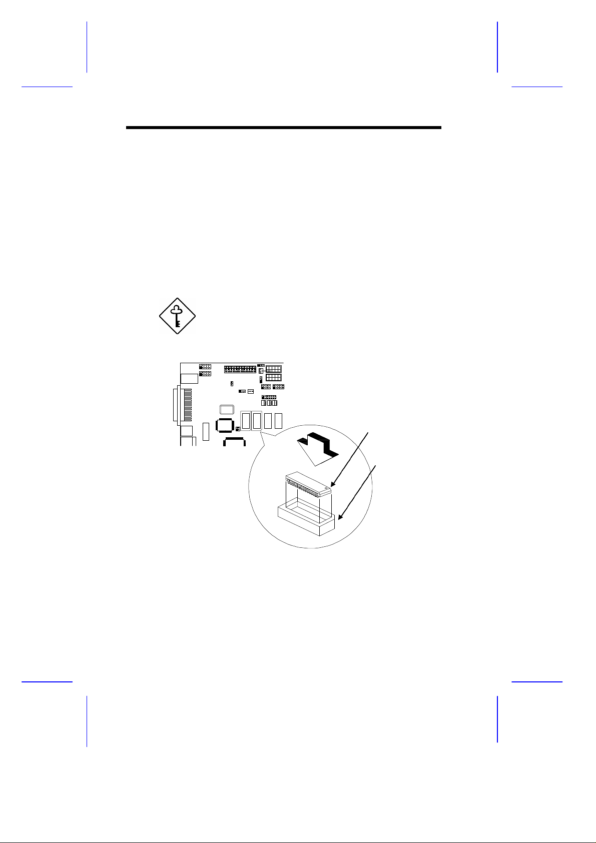
1.6 Video Memory Upgrade
Notched Corner
Larger video memory allows you to display higher resolutions and
more colors. The system board comes with a 1-MB video memory
onboard upgradable to 2 MB.
Follow these steps to upgrade the video memory:
1. Locate the video DRAM upgrade sockets labeled U36 and U37
on the system board. See Figure 1-1.
2. Gently insert a video chip into each of the upgrade sockets.
Make sure that the pin 1 indicator on the chip
matches the notched corner of the socket.
Pin 1 Indicator
Figure 1-3 Installing a Video Memory Chip
1-8 User’s Guide
Page 26

1.7 ASM Pro
The ASM Pro is a server management tool based on the Simple
Network Management Protocol (SNMP). It detects server problems
related to the CPU thermal condition, 5V/3.3V/1.5V detection, or PCI
bus utilization calculation.
This feature is designed primarily for server supervisors and
management information system (MIS) personnel to help them detect
errors or potential trouble spots in their network servers through a
single management station.
The ASM Pro consists of two major parts:
• ASM-Station - a Windows-based monitoring station that
communicates with the ASM-Agents.
• ASM-Agent(s) - the individual servers managed by the
ASM-Station.
Refer to the ASM Pro user’s manual for more information.
System Board 1-9
Page 27

1.8 Remote Diagnostic Management
The Remote Diagnostic Management (RDM) is a network
management tool that utilizes modems and telephone lines to control
a host of servers from a remote station. It monitors and analyzes the
server condition, updates the BIOS settings if necessary, or reboots
the server in the event of failure and quickly return it to normal
operation. This capability to execute the RDM program from a
remote site bridges the distance barrier in fixing server problems and
reduces wasted time due to system failure.
1.8.1 Installing the RDM Module
The system board comes with connectors CN27 and CN28 to
accommodate the RDM module.
Follow these steps to install the RDM module and connect the cable:
1. See Figure 1-1 for the location of the RDM connectors.
2. Gently insert the RDM module into CN27 and CN28. The
module fits only in one direction. Do not force it into to the
connectors.
CN28
CN27
Figure 1-4 Installing the RDM Module
Refer to the RDM User’s Guide for detailed instructions on RDM
installation.
1-10 User’s Guide
Page 28

1.9 Error Messages
Do not continue using the computer if you receive an error message
of any type. Note the message and take corrective action. This
section explains the different types of error messages and
corresponding corrective measures.
There are two general types of error messages:
• Software
• System
1.9.1 Software Error Messages
Software error messages are returned by your operating system or
application. These messages typically occur after you boot the
operating system or when you run your applications. If you receive
this type of message, consult your application or operating system
manual for help.
1.9.2 System Error Messages
A system error message indicates a problem with the computer itself.
A message of this type normally appears during the power-on selftest, before the operating system prompt appears.
Table 1-3 lists the system error messages.
System Board 1-11
Page 29

Table 1-3 System Error Messages
Message Action
CMOS Battery Error Replace the RTC chip or
contact your dealer.
CMOS Checksum Error Check the RTC chip and the
necessary jumper. If the
battery is still good, run
Setup.
Display Card Mismatch Run Setup.
Diskette Drive Controller
Error or Not Installed
Diskette Drive Error Diskette may be defective. If
Diskette Drive A Type
Mismatch
Diskette Drive B Type
Mismatch
Equipment Configuration
Error
Hard disk Controller Error Run Setup.
Hard disk 0 Error Check all cable connections.
Hard disk 1 Error Check all cable connections.
Keyboard Error or No
Keyboard Connected
Keyboard Interface Error Replace the keyboard or
Check and connect the
control cable to the diskette
controller.
not, replace the diskette drive.
Run Setup and select the
proper drive type.
Run Setup and select the
proper drive type.
Modify the memory
configuration to agree with
one of the options in Table
2-x.
Replace hard disk.
Replace hard disk.
Check and connect the
keyboard to the system unit.
contact your dealer.
1-12 User’s Guide
Page 30

Table 1-3 System Error Messages (continued)
Message Action
Memory Error at:
MMMM:SSSS:OOO
(W:XXXX, R:YYYY)
where:
M: MB, S: Segment,
O: Offset, X/Y: write/read
pattern
Memory Size Mismatch
CPU Clock Mismatch
Onboard Serial Port 1
Conflict
Onboard Serial Port 2
Conflict
Onboard Parallel Port
Conflict
Pointing Device Error Check and connect pointing
Pointing Device Interface
Error
Press F1 key to continue or
Ctrl-Alt-Esc for Setup
Real Time Clock Error Check the RTC chip. If it is
CPU BIOS Code Mismatch Contact your dealer.
Check installed DIMMs.
Contact your dealer.
Run Setup. Check if the
values shown in the memory
parameters are correct. If
correct, exit Setup and reboot
the system. If the error
message reappears, seek
technical assistance.
Run Setup and disable the
port.
Run Setup and disable the
port.
Run Setup and disable the
port.
device.
Replace the pointing device or
contact your dealer.
Press or
+ + to enter
Setup.
still good, run Setup. If not,
replace the RTC chip.
System Board 1-13
Page 31

1.9.3 Correcting Error Conditions
As a general rule, if an error message says "Press F1 to continue," it
is caused by a configuration problem, which can be easily corrected.
An equipment malfunction is more likely to cause a fatal error, i.e., an
error that causes complete system failure.
Here are some corrective measures for error conditions:
1. Run Setup. You must know the correct configuration values for
your system before you enter Setup, which is why you should
write them down when the system is correctly configured. An
incorrect configuration is a major cause of power-on error
messages, especially for a new system.
2. Remove the system unit cover. Check that the jumpers on the
system board and any expansion boards are set correctly.
3. If you cannot access a new disk, it may be because your disk is
not properly formatted. Format the disk first using the FDISK
and FORMAT commands.
4. Check that all connectors and boards are securely plugged in.
If you go through the corrective steps above and still receive an error
message, the cause may be an equipment malfunction.
If you are sure that your configuration values are correct and your
battery is in good condition, the problem may lie in a damaged or
defective chip.
In either case, contact an authorized service center for assistance.
1-14 User’s Guide
Page 32

Chapter
22
CPU Board
The CPU board carries two sockets to support a powerful dual-CPU
configuration. The sockets accommodate the new Intel Pentium II
CPU running at 233/266 MHz. The Pentium II CPU incorporates the
first-level cache and boasts a new generation of power.
The board comes with four DRAM banks composed of four 168-pin
dual-inline memory module (DIMM) sockets that accommodate both
fast-page mode and EDO (extended data output) DIMMs.
Designed to work with Intel 440FX PCIset, the board includes the PCI
bridge/memory controller (PMC) and the data bus accelerator (DBX)
chipsets. The PMC provides bus control signals and address paths
for transfers between the host bus, PCI bus, and the main memory.
The DBX supports multiple-bit error detection and single-bit error
correction through the ECC/parity feature.
CPU Board 2-1
Page 33

2.1 Layout
Pentium II CPU Socket 1
Pentium II CPU Socket 2
Figure 2-1 CPU Board Layout
2.2 Jumper Locations
CPU Voltage Regulators
DIMM Sockets
Figure 2-2 Pentium II CPU Board Jumper Locations
2-2 User’s Guide
Page 34

2.3 Jumper Settings
Table 2-1 Settings for CPU Core/Bus Frequency Ratio (JP1)
JP1 Settings
1-2 3-4 5-6 7-8 CPU Core/Bus Freq.
1 1 1 1 2
1 1 0 1 3
1 1 1 0 4
1 1 0 0 2.5
1 0 0 1 3.5
0 - Pins open 1 - Pins Closed
Table 2-2 ITP Debug Port (JP2)
JP2
1-2 2-3 ITP
1 0 CPU 1*
0 1 CPU 2
0 - Pins open 1 - Pins closed
Table 2-3 Clock Settings (JP5)
*
JP5 CPU
1-2 2-3 Clock Speed
1 0 66 MHz*
0 1 60 MHz
0 - Pins open 1 - Pins closed
*
Default setting
CPU Board 2-3
Page 35

2.4 Memory Upgrade
The system board comes with eight 168-pin sockets, labeled DIMM1
to DIMM4, that accommodate single-density and double-density
DIMMs. The sockets support both the fast-page mode and EDO
DIMMs for a total of 512-MB system memory using 128-MB DIMMs.
Table 2-4 lists some possible memory configurations.
2.4.1 Memory Configurations
Table 2-4 Memory Configurations
DIMM1 DIMM2 DIMM3 DIMM4 Total Memory
32 MB 32 MB
32 MB 32 MB 64 MB
32 MB 32 MB 32 MB 96 MB
32 MB 32 MB 32 MB 32 MB 128 MB
32 MB 32 MB 64 MB 64 MB 192 MB
64 MB 64 MB
64 MB 64 MB 128 MB
64 MB 64 MB 64 MB 192 MB
64 MB 64 MB 64 MB 64 MB 256 MB
64 MB 64 MB 128 MB 128 MB 384 MB
128 MB 128 MB
128 MB 128 MB 256 MB
128 MB 128 MB 128 MB 384 MB
128 MB 128 MB 128 MB 128 MB 512 MB
The above configurations are only some of
the available memory combinations. When
upgrading memory, simply install DIMMs into
any of the empty sockets.
2-4 User’s Guide
Page 36

2.4.2 Installing a DIMM
To install a DIMM, align it with the socket and press it down until the
holding clips secure the DIMM in place.
The DIMM socket is slotted to ensure proper
installation. If you slip in a DIMM but does
not completely fit, you may have inserted it
the wrong way. Reverse the orientation of
the DIMM.
Figure 2-3 Installing a DIMM
CPU Board 2-5
Page 37

2.4.3 Removing a DIMM
To remove a DIMM, press the holding clips on both sides of the
socket outward to release the DIMM.
Place your forefingers on the top of the
DIMM before you press the holding clips to
gently disengage the DIMM from the socket.
Figure 2-4 Removing a DIMM
2-6 User’s Guide
Page 38

2.4.3 Reconfiguring the System
You must enter Setup after installing or removing SIMMs to
reconfigure the system.
Follow these steps to reconfigure the system:
1. Turn the system on. A memory error message appears,
indicating that the total memory does not match the value stored
in CMOS.
2. Press + + to enter Setup. A warning message
appears indicating an incorrect memory configuration.
3. Press twice to exit and reboot the system.
The system boots with the new memory configuration.
CPU Board 2-7
Page 39

2.5 Installing the Processor Heat Sink
and Fan
The Pentium II processor module comes with holes on one side to
hold the clips of the heat sink and fan. The upper set of holes (near
the latches) on the processor are wider and should match the wider
ends of the clips on the heat sink. The lower set of holes are smaller
and should match the narrow ends of the heat sink clips.
Wide Clip Ends
Wide Holes
Narrow Holes
Figure 2-5 Matching the Fan-Heat Sink Clips with the Holes on
the Processor
2-8 User’s Guide
Page 40

Follow these steps when installing the heat sink and fan to the
Pentium II processor module:
1. Remove the thermal tape protector at the back of the heat sink.
2. Insert the wide clip ends to the wide holes on the processor and
the narrow clip ends to the narrow holes.
Figure 2-6 Inserting the Clip Ends to the Processor Holes
3. Use a screwdriver to press and lock in the wide end of a clip first.
Then without lifting the screwdriver, point it downward to press
and lock the narrow end of the clip. See Figures 7 and 8 for the
illustration of this step.
CPU Board 2-9
Page 41

Figure 2-7 Locking a Wide Clip End
Figure 2-8 Locking a Narrow Clip End
4. Repeat step 3 to lock the other clip.
2-10 User’s Guide
Page 42

2.6 Installing a Pentium II Processor
Follow these steps to install the Pentium II processor to the socket on
the CPU board.
1. Place the retention mechanism over the processor socket on the
CPU board. Secure it with the screws that came with the
package.
Figure 2-9 Installing the Pentium II Retention Mechanism
2. With the processor module golden fingers pointing downward,
align the processor to the posts of the retention mechanism then
lower it down. See Figure 2-10.
The golden fingers of the Pentium II module
is slotted such that it only fits in one direction.
Make sure that module groove matches the
one on the processor socket.
CPU Board 2-11
Page 43

3. Press down the processor module until the golden fingers
completely fit into the socket.
Figure 2-10 Installing a Pentium II Processor
4. Press the latches on the sides to lock the processor module into
place.
Figure 2-11 Securing the Pentium II Processor
2-12 User’s Guide
Page 44

2.7 Removing a Pentium II Processor
Follow these steps to remove the Pentium II CPU module from the
slot.
1. Unlock the latches the secure that processor module.
Figure 2-12 Unlocking the Module Latches
2. Firmly hold the processor module and pull it out of the socket.
Figure 2-13 Removing the Pentium II Processor
CPU Board 2-13
Page 45

2.8 CPU Board Installation
After setting the jumpers and installing memory modules and CPUs,
install the CPU board into the CPU board slot on the system board.
Follow these steps to install the CPU board:
1. Position the CPU board over the slot on the system board such
that the component side (CPU side) faces upward.
2. Gently insert the golden fingers of the board into the slot.
Figure 2-14 Installing the CPU Board
Make sure that the CPU board is properly
seated in the slot.
2-14 User’s Guide
Page 46

Chapter
33
BIOS Utility
Most systems are already configured by the manufacturer or the
dealer. There is no need to run Setup when starting the computer
unless you get a Run Setup message.
If you repeatedly receive Run Setup
messages, the battery may be bad. In this
case, the system cannot retain configuration
values in CMOS. Ask a qualified technician
for assistance.
Before you run Setup, make sure that you have saved all open files.
The system reboots immediately after you exit Setup.
BIOS Utility 3-1
Page 47

3.1 Entering Setup
To enter Setup, press the key combination + +
You must press + + while the
system is booting. This key combination
does not work during any other time.
The BIOS Utility main menu then appears:
BIOS Utility
Basic System Configuration
Advanced System Configuration
PCI System Configuration
Power Saving Configuration
System Security
Load Setup Default Settings
.
↑↓ = Move Highlight Bar, ↵ = Select, Esc = Exit and Reboot
The parameters on the following screens show
default values. These values may not be the same
as those in your system.
The grayed items (denoted with asterisks) on the
following screens have fixed settings and are
non-configurable.
3-2 User’s Guide
Page 48

3.2 Basic System Configuration
Select Basic System Configuration to input configuration values such
as date, time, and disk types.
The following screen shows the Basic System Configuration menu.
Basic System Configuration Page 1/2
Date ..................... [MM/DD/YY]
Time ..................... [HH:MM:SS]
Diskette Drive A ......... [xx-MB xx-inch]
Diskette Drive B ......... [xx-MB xx-inch]
Onboard IDE .............. [Enabled ]
Cylinder Head Sector
IDE Drive 0 (xxx MB)..... [Auto] xx xx xx
IDE Drive 1 (xxx MB)..... [Auto] xx xx xx
Total Memory ............. [ xxx] MB
↑↓ = Move Highlight Bar, → ← = Change Setting
PgDn/PgUp = Move Screen, F1 = Help, Esc = Exit
The command line at the bottom of the menu tells you how to
highlight items, change settings, and move from one screen to
another.
Press or on the cursor-edit keypad to highlight the desired
parameter.
Press or to select the desired option for a parameter.
Press to move to the next page or to return to the previous
page.
Press to exit the configuration menu.
BIOS Utility 3-3
Page 49

The following screen shows page 2 of the Basic System Configuration
menu.
Basic System Configuration Page 2/2
Enhanced IDE Features
Hard Disk Block Mode .......... [Enabled ]
Advanced PIO Mode ............. [Enabled ]
Hard Disk Size > 504MB ........ [Enabled ]
Hard Disk 32-bit Access ....... [Enabled ]
Num Lock After Boot .............. [Enabled ]
Memory Test ...................... [Disabled]
Quiet Boot ....................... [Disabled]
Configuration Table .............. [Enabled ]
↑↓ = Move Highlight Bar, → ← = Change Setting
PgDn/PgUp = Move Screen, F1 = Help, Esc = Exit
The following sections explain the different parameters and their
settings.
3.2.1 Date and Time
The real-time clock keeps the system date and time. After setting the
date and time, you need not enter them every time you turn on the
system. As long as the internal battery remains good (approximately
seven years) and connected, the clock continues to keep the date and
time accurately even when the power is off.
Date
Highlight the items on the date parameter and press or to set
the date following the month-day-year format.
Valid values for month, day, and year are:
• Month 1 to 12
3-4 User’s Guide
Page 50

• Day 1 to 31
• Year 00 to 99
Time
Highlight the items on the time parameter and press or to set
the time following the hour-minute-second format.
Valid values for hour, minute, and second are:
• Hour 00 to 23
• Minute 00 to 59
• Second 00 to 59
3.2.2 Diskette Drives
To enter the configuration value for the first diskette drive (drive A),
highlight the Diskette Drive A parameter. Press or key to view
the options and select the appropriate value.
Possible settings for the Diskette Drive parameters:
• [ None ]
• [360 KB, 5.25-inch]
• [1.2 MB, 5.25-inch]
• [720 KB, 3.5-inch]
• [1.44 MB, 3.5-inch]
• [2.88 MB, 3.5-inch]
Follow the same procedure for Diskette Drive B. Choose None if you
do not have a second diskette drive.
BIOS Utility 3-5
Page 51

3.2.3 Onboard IDE
When set to Enabled, this parameter enables the IDE drives installed
in the system. Setting to Disabled deactivates the IDE drives and
grays the IDE Drive parameters.
3.2.4 IDE Drives
Move the highlight bar to the IDE Drive 0 parameter to configure the
first IDE drive (drive C). Press or to display the IDE hard disk
types with their respective values. Select the type that corresponds to
your drive. Follow the same procedure for the other drives, if any.
Choose None if you do not have other drives.
Selecting the “Auto” Option
If you do not know the exact type of your IDE drive, select the option
Auto. During the power-on self-test (POST), when the system
performs self-testing and self-initialization before loading the
operating system and applications, the BIOS utility automatically
determines your IDE drive type. You can see the drive type and its
values when you enter the BIOS Utility.
Cylinder Head Sector
IDE Drive 0 (xx MB) ... [Auto] xx xx xx
3-6 User’s Guide
Page 52

If desired, you can save the values under the option User.
Cylinder Head Sector
IDE Drive 0 (xx MB) ... [User] xx xx xx
The next time you boot the system, the BIOS utility does not have to
auto-configure your IDE drive as it detects the saved disk information
during POST.
We recommend that you copy the IDE disk
drive values and keep them in a safe place in
case you have to reconfigure the disk in the
future.
Follow the same procedure to auto-configure other IDE drives.
Selecting the “User” Option
There are cases when you cannot use the option Auto, instead you
have to select User. Choose the User option when you have
installed an hard disk that was previously formatted but does not use
the disk native parameters or structure, that is, the disk type may be
in the hard disk types list but the number of cylinders, heads, and
sectors differ.
Follow these steps to configure a hard disk with the User option:
1. Highlight an hard disk parameter.
2. Select the option User and press .
3. Type in the number of cylinders, heads, and sectors of the drive
under the appropriate columns.
Be sure to have the correct hard disk
information beforehand.
BIOS Utility 3-7
Page 53

4. Choose YES when asked if you want to save CMOS data.
3.2.5 Total Memory
The system automatically detects the total amount of onboard
memory during the POST and sets the memory parameters
accordingly. If you install additional memory, the system
automatically adjusts this parameter to display the new memory size.
3.2.6 Enhanced IDE Features
Hard Disk Block Mode
This function enhances disk performance depending on the hard disk
in use. If you set this parameter to Enabled, it allows data transfer in
block (multiple sectors) by increasing the data transfer rate to 256
bytes per cycle. If your system does not boot after enabling this
parameter, change the setting to Disabled. This parameter is
normally set to Enabled .
Advanced PIO Mode
Enabling this parameter improves system performance by allowing
the use of faster hard drives. If your hard disk does not support this
function, set this parameter to Disabled . The default if Enabled .
Hard Disk Size > 504 MB
If enabled, BIOS allows you to use a hard disk with a capacity of
more than 504 MB. This is made possible through the Logical Block
Address (LBA) mode translation. Other operating systems require
this parameter to be set to Disabled .
3-8 User’s Guide
Page 54

To prevent data loss, set this parameter set to Enabled if you are
using a hard disk with more than 504 MB capacity that was previously
configured through LBA mode. If you use a hard disk configured
through cylinder-head-sector (CHS) mode, set this parameter to
Disabled . The default is Enabled .
Hard Disk 32-bit Access
Enabling this parameter improves system performance by allowing
the use of the 32-bit hard disk access. This enhanced IDE feature
only works under DOS, Windows 3.x, Windows 95, and Novell
NetWare. If your software or hard disk does not support this function,
set this parameter to Disabled . The default is Enabled .
3.2.7 Num Lock After Boot
This parameter allows you to activate the Num Lock function upon
booting. The default setting is Enabled.
3.2.8 Memory Test
When set to Enabled, this parameter allows the system to perform a
RAM test during the POST routine. When set to Disabled, the
system detects only the memory size and bypasses the test routine.
The default setting is Disabled .
3.2.9 Quiet Boot
This parameter enables or disables the quiet boot function. When set
to Enabled, BIOS is in graphical mode and displays only an
identification logo during POST and while booting. After which the
screen displays the operating system prompt (such as DOS) or logo
(such as Windows 95). If any error occurred while booting, the
system automatically switches to text mode.
BIOS Utility 3-9
Page 55

Even if your setting is Enabled, you may also switch to the text mode
while booting by pressing after you hear a beep that indicates the
activation of the keyboard.
When set to Disabled, BIOS is in the conventional text mode where
you see the system initialization details on the screen.
3.2.10 Configuration Table
This parameter allows you to display the configuration table after
POST but before booting. The configuration table gives a summary
of the hardware devices and settings that BIOS detected during
POST. Following is a sample configuration table.
CPU ID :Pentium II
CPU Clock :xxx MHz
Math Coprocessor: Installed
IDE Drive 0 : xxx MB
IDE Drive 1 : xxx MB
IDE Drive 2 : xxx MB
IDE Drive 3 : xxx MB
Diskette Drive A: xx-MB, xx-inch
Diskette Drive B: None
Pointing Device: None
ECC/Parity Mode: ECC
Base Memory: : xxx KB
Extended Memory: xxxx KB
Shadow RAM : xxx KB
Internal Cache : xxx KB, Enabled
External Cache : xxx KB, Enabled
Serial Port(s) : 3F8h, 2F8h
Parallel Port : 378h
DRAM Bank 0 : None
DRAM Bank 1 : None (EDO)
DRAM Bank 2 : None
DRAM Bank 3 : None
3-10 User’s Guide
Page 56

3.3 Advanced System Configuration
The Advanced System Configuration option allows you to configure
the advanced system memory functions.
Do not change any settings in the Advanced
Configuration if you are not a qualified
technician to avoid damaging system.
The following screen shows page one of the Advanced System
Configuration parameters.
Advanced System Configuration Page 1/1
Internal Cache (CPU Cache) .......... [Enabled ]
External Cache (CPU Cache) ........... [Enabled ]
Cache Scheme ....................... [Write back]
ECC/Parity Mode Selection ........... [ ECC ]
Operation of ECC ................... [Correction Enabled]
Memory at 15MB-16MB Reserved for ..... [ System ] Use
↑↓ = Move Highlight Bar, → ← = Change Setting
PgDn/PgUp = Move Screen, F1 = Help, Esc = Exit
3.3.1 Internal Cache (CPU Cache)
This parameter enables or disables the first-level cache memory
integrated in the Pentium II CPU.
BIOS Utility 3-11
Page 57

3.3.2 External Cache (CPU Cache)
This parameter enables or disables the second-level cache memory.
Cache Scheme
This parameter allows you to select Write back or Write through
for the cache mode. Write back updates the cache but not the
memory when there is a write instruction. It updates the memory only
when there is an inconsistency between the cache and the memory.
Write through updates both the cache and the memory whenever
there is a write instruction.
3.3.3 ECC/Parity Mode Selection
This parameter allows you to select ECC, Parity, or Disabled . The
ECC option allows single-bit error detection and automatic correction.
The automatic correction depends on the setting of the parameter
Operation of ECC. See section 3.3.4 for details.
ECC also detects multiple-bit errors but does not correct them.
Instead, it issues a non-maskable interrupt (NMI) signaling the
operating system of the multiple-bit error detection.
The Parity option allows parity check. If it detects any parity errors,
it sets up the parity error flag in the chipset. This signals the
operating system of the parity error detection.
Fast-page mode SIMMs with parity support both ECC and parity
mode. EDO SIMMs with parity support only ECC mode.
Both the ECC and parity check features
require parity SIMMs. You must disable this
parameter if you installed SIMMs without
parity.
3-12 User’s Guide
Page 58

3.3.4 Operation of ECC
This parameter allows you to enable or disable the error correction
function. In the option Correction Enabled, ECC automatically
corrects any single-bit errors detected. For multiple-bit errors
detected, ECC only issues an NMI to signal the operating system of
the multiple-bit error detection.
In the option Correction Disabled, ECC detects both single-bit
and multiple-bit errors but does not correct either one. It only issues
an NMI to signal the operating system of the error detection.
This parameter is grayed if the ECC/Parity Mode Selection parameter
is set to either Parity or Disabled . Refer to section 3.3.3.
3.3.5 Memory at 15MB-16MB
To prevent memory address conflicts between the system and
expansion boards, reserve this memory range for the use of either the
system or an expansion board. Before setting this parameter, check
your add-on card manual to determine if your add-on card needs this
memory space. If not, set this parameter to System Use.
BIOS Utility 3-13
Page 59

3.4 PCI System Configuration
The PCI System Configuration allows you to specify the settings for
your PCI devices.
PCI System Configuration Page 1/2
PCI IRQ Setting ........... [ Auto ]
PCI Slot 1 ............ [--] [--] [--] [--]
PCI Slot 2 ............ [--] [--] [--] [--]
PCI Slot 3 ............ [--] [--] [--] [--]
PCI Slot 4 ............ [--] [--] [--] [--]
PCI Slot 5 ............ [--] [--] [--] [--]
Onboard LAN ........... [--]
Onboard SCSI1 ......... [--]
Onboard SCSI2 ......... [--]
VGA Palette Snoop ......... [Disabled]
↑↓ = Move Highlight Bar, → ← = Change Setting
PgDn/PgUp = Move Screen, F1 = Help, Esc = Exit
PCI System Configuration Page 2/2
INTA INTB INTC INTD
Onboard LAN ............... [Enabled ]
USB Host Controller ........ [Disabled]
Onboard SCSI1 ............. [Enabled ]
Boot SCSI1 Device ..... [Enabled ]
Onboard SCSI2 ............. [Enabled ]
Boot SCSI2 Device ..... [Enabled ]
PCI IRQ Sharing ............ [No ]
Plug & Play OS ............. [Yes]
Reset Resources Assignment . [No ]
↑↓ = Move Highlight Bar, → ← = Change Setting
PgDn/PgUp = Move Screen, F1 = Help, Esc = Exit
3-14 User’s Guide
Page 60

3.4.1 PCI IRQ Setting
This parameter allows for Auto or Manual configuration of PCI
devices. If you use plug-and-play (PnP) devices, set this parameter
to Auto. The system then automatically assigns IRQ to the PnP
devices. If your PCI device is not a PnP, you can manually assign
the interrupt for each device. Refer to your manual for technical
information about the PCI card.
When the PCI IRQ Setting is set to Auto, all
the IRQ setting fields become gray and nonconfigurable.
PCI Slots
These parameters allow you to specify the appropriate interrupt for
each of the PCI devices. You can assign IRQ3, IRQ4, IRQ5, IRQ7,
IRQ9, IRQ10, IRQ11, IRQ12, IRQ14, or IRQ15 to the slots.
The items PCI Slot 4 and Onboard SCSI share the same IRQ.
Setting an interrupt for the former automatically sets that same
interrupt for the latter.
Make sure that the interrupt you assign in
any of the PCI slots are not used by other
devices to avoid conflicts.
Press or to move between fields. Press or to select
options.
Onboard LAN
This item allows you to manually assign the interrupt for the onboard
LAN when the PCI IRQ Setting parameter is set to Manual . This
parameter is grayed and not user-configurable when the PCI IRQ
Setting is set to Auto and when the Onboard LAN parameter is set to
Disabled .
BIOS Utility 3-15
Page 61

Onboard SCSI1/Onboard SCSI2
These items allow you to manually assign the interrupts for the
onboard SCSI hard disks when the PCI IRQ Setting parameter is set
to Manual. These parameters are grayed and not user-configurable
when the PCI IRQ Setting is set to Auto and when the Onboard
SCSI1 and Onboard SCSI2 parameters on page 2 are set to
Disabled .
Make sure to assign an IRQ to this item if
you set the PCI IRQ Setting parameter to
Manual.
Press or to move between fields. Press or to select
options.
3.4.2 VGA Palette Snoop
This parameter permits you to use the palette snooping feature if you
installed more than one VGA card in the system.
The VGA palette snoop function allows the control palette
register (CPR) to manage and update the VGA RAM DAC (Digital
Analog Converter, a color data storage) of each VGA card installed in
the system. The snooping process lets the CPR send a signal to all
the VGA cards so that they can update their individual RAM DACs.
The signal go through the cards continuously until all RAM DAC data
have been updated. This allows display of multiple images on the
screen.
Some VGA cards have required settings for
this feature. Check your VGA card manual
before setting this parameter.
3-16 User’s Guide
Page 62

3.4.3 Onboard LAN
This parameter allows you to enable or disable the onboard LAN
feature.
3.4.4 USB Host Controller
This parameter allows you to enable or disable the onboard USB host
controller and the external USB ports.
3.4.5 Onboard SCSI1
This parameter allows you to enable or disable the onboard SCSI1
device.
Boot SCSI1 Device
This parameter allows you to enable or disable the onboard SCSI1 as
a boot device priority.
3.4.6 Onboard SCSI2
This parameter allows you to enable or disable the onboard SCSI2
device.
Boot SCSI2 Device
This parameter allows you to enable or disable the onboard SCSI2 as
a boot device priority.
3.4.7 PCI IRQ Sharing
When set to Yes, this parameter allows you to assign the same IRQ
to more than one PCI device installed in the system. When set to No,
you must assign different IRQs to the PCI devices.
BIOS Utility 3-17
Page 63

3.4.8 Plug & Play OS
When this parameter is set to Yes, BIOS initializes only PnP boot
devices such as SCSI cards. When set to No, BIOS initializes all PnP
boot and non-boot devices such as sound cards.
Set this parameter to Yes only if your operating
system is Windows 95.
3.4.9 Reset Resources Assignment
Set this parameter to Yes to avoid IRQ conflict when installing
non-PnP or PnP ISA cards. This clears all resource assignments and
allows BIOS to reassign resources to all installed PnP devices the
next time the system boots. After clearing the resource data, the
parameter resets to No.
3-18 User’s Guide
Page 64

3.5 Power Saving Configuration
The Power Saving Configuration parameters are configurable only if
your system supports the power management feature.
The following screens show the Power Saving Configuration
parameters and their default settings:
Power Saving Configuration Page 1/1
Power Management Mode ................[Disabled]
IDE Hard Disk Standby Timer .......[15] Minute(s)
System Standby Timer ..............[ 5] Minute(s)
System Suspend Timer ..............[15] Minutes
Monitored Activities
IRQ 0 ...... [Disabled] IRQ 8 ...... [Disabled]
IRQ 1 ...... [Enabled ] IRQ 9 ...... [Disabled]
IRQ 3 ...... [Disabled] IRQ 10 ..... [Disabled]
IRQ 4 ...... [Disabled] IRQ 11 ..... [Disabled]
IRQ 5 ...... [Disabled] IRQ 12 ..... [Enabled ]
IRQ 6 ...... [Enabled ] IRQ 13 ..... [Enabled ]
IRQ 7 ...... [Disabled] IRQ 14 ..... [Enabled ]
↑↓ = Move Highlight Bar, → ← = Change Setting
PgDn/PgUp = Move Screen, F1 = Help, Esc = Exit
IRQ 15 ..... [Disabled]
BIOS Utility 3-19
Page 65

3.5.1 Power Management Mode
This parameter allows you to reduce power consumption. When this
parameter is set to Enabled, you can configure the system timers.
Setting to Disabled deactivates the power management feature and
all the timers.
For system models with RDM module
installed, enabling the RDM feature disables
the power management parameters.
IDE Hard Disk Standby Timer
This parameter allows the hard disk to enter standby mode after
inactivity of 1 to 15 minutes, depending on your setting. When you
access the hard disk again, allow 3 to 5 seconds (depending on the
hard disk) for the disk to return to the normal speed. Set this
parameter to Off if your hard disk does not support this function.
System Standby Timer
This parameter sets the system to a "fast-on" power saving mode. It
automatically enters the standby mode after a specified period of
inactivity. Any keyboard or mouse action, or any enabled monitored
activities occurring through IRQ channels, resume system operation.
See section 2.5.2.
System Suspend Timer
This parameter sets the system to a "fast-on" power saving mode. It
automatically enters the standby mode after a specified period of
inactivity. Any keyboard or mouse action, or any enabled monitored
activities occurring through the IRQ channels, resume system
operation. See section 2.5.2.
3-20 User’s Guide
Page 66

3.5.2 Monitored Activities
This parameter allows you to monitor system activities occurring
through the IRQ and determine whether or not to enter power saving
mode.
For example, if you assign IRQ3 to a fax/modem and you set this
item to Enabled, any fax/modem activity wakes up the system from
suspend mode.
BIOS Utility 3-21
Page 67

3.6 System Security
The Setup program has a number of security features to prevent
unauthorized access to the system and its data.
Enter the Setup program and select System Security to display the
following screen.
System Security Page 1/1
Disk Drive Control
Diskette Drive.................. [ Normal ]
Hard Disk Drive................. [ Normal ]
System Boot Drive............... [Drive A then C]
Onboard Communication Ports
Serial Port 1 Base Address...... [ 3F8h ]
Serial Port 2 Base Address...... [ 2F8h ]
Parallel Port Base Address...... [378 (IRQ 7]
Operation Mode...............[Standard Parallel Port (SPP)] Mode
*ECP DMA Channel ......... [-]
Onboard PS/2 Mouse (IRQ12) ... [Enabled ]
Setup Password .................... [ None ]
Power On Password ................. [ None ]
↑↓ = Move Highlight Bar, → ← = Change Setting
PgDn/PgUp = Move Screen, F1 = Help, Esc = Exit
3.6.1 Disk Drive Control
The disk drive control features allow you to enable or disable the
read/write functions of a disk drive. These features can also control
the diskette drive or the hard disk drive boot function to prevent
loading operating systems or other programs from a certain drive
while the other drives are operational.
Table 3-1 lists the drive control settings and their corresponding
functions.
3-22 User’s Guide
Page 68

Table 3-1 Drive Control Settings
Setting Description
Diskette Drive
Normal Diskette drive functions normally
Write Protect All Sectors Disables the write function on all sectors
Write Protect Boot Sector Disables the write function only on the boot
Disabled Disables all diskette functions
Hard Disk Drive
Normal Hard disk drive functions normally
Write Protect All Sectors Disables the write function on all sectors
Write Protect Boot Sector Disables the write function only on the boot
Disabled Disables all hard disk functions
System Boot Drive
Drive A then C The system checks drive A first. If there is a
Drive C then A The system checks drive C first. If there is a
C: The system always boots from drive C.
A: The system always boots from drive A.
sector
sector
diskette in the drive, the system boots from drive
A. Otherwise, it boots from drive C.
hard disk (drive C) installed, the system boots
from drive C. Otherwise, it boots from drive A.
BIOS Utility 3-23
Page 69

3.6.2 Onboard Communication Ports
Serial Port 1 Base Address
This parameter allows you to set the serial port 1 logical base
address.
Table 3-2 Serial Port 1 Settings
Setting Description
3F8h Serial port 1 with address 3F8h using IRQ4
2F8h Serial port 1 with address 2F8h using IRQ3
3E8h Serial port 1 with address 3E8h using IRQ4
2E8h Serial port 1 with address 2E8h using IRQ3
Disabled Disables serial port 1
Serial Port 2 Base Address
This parameter allows you to set the serial port 2 logical base
address.
Table 3-3 Serial Port 2 Settings
Setting Description
3F8h Serial port 2 with address 3F8h using IRQ4
2F8h Serial port 2 with address 2F8h using IRQ3
3E8h Serial port 2 with address 3E8h using IRQ4
2E8h Serial port 2 with address 2E8h using IRQ3
Disabled Disables serial port 2
If you assign 3F8h to serial port 1, you may
only assign 2F8h or 2E8h to serial port 2.
If you assign 2F8h to serial port 1, you may
3-24 User’s Guide
Page 70

only assign 3F8h or 3E8h to serial port 2.
Parallel Port Base Address
The system has one parallel port. Table 3-4 lists the options for
selecting the parallel port address. You also have the option to
disable the parallel port.
Table 3-4 Parallel Port Settings
Setting Function
3BCh (IRQ 7) Corresponds to the parallel port with
address 3BCh
378h (IRQ 7) Corresponds to the parallel port with
address 378h
278h (IRQ 5) Corresponds to the parallel port with
address 278h
Disabled Disables the parallel port
To deactivate the parallel port, select the Disabled option. If you
install an add-on card with a parallel port whose address conflicts with
the onboard parallel port, the system automatically disables the
onboard functions.
Check the parallel port address on the add-on card and change the
address to one that does not conflict.
BIOS Utility 3-25
Page 71

OPERATION MODE
This item allows you to set the operation mode of the parallel port.
Table 3-5 lists the different operation modes.
Table 3-5 Parallel Port Operation Mode Settings
Setting Function
Standard Parallel Port (SPP) Allows normal speed one-way
operation
Standard and Bidirectional Allows normal speed operation in
a two-way mode
Enhanced Parallel Port (EPP) Allows bidirectional parallel port
operation at maximum speed
Extended Capabilities Port
(ECP)
ECP DMA CHANNEL
Allows parallel port to operate in
bidirectional mode and at a speed
higher than the maximum data
transfer rate
This item becomes active only if you select Extended
Capabilities Port (ECP) as the operation mode. It allows you to
select DMA channel 1 or DMA channel 3 depending on the available
system resource.
3.6.3 Onboard PS/2 Mouse (IRQ12)
This parameter enables or disables the onboard PS/2 mouse. When
set to Enabled, it allows you to use the onboard PS/2 mouse
assigned with IRQ12. When set to Disabled, it deactivates the
mouse and frees IRQ12 for the use of other devices.
3-26 User’s Guide
Page 72

3.6.4 Setup Password
The setup password prevents unauthorized access to the BIOS utility.
Setting a Setup Password
1. Make sure that jumper JP3 is set to pins 2-3 (bypass).
You cannot enter the BIOS utility if a setup
password does not exist and jumper JP3 is
set to pins 1-2 (check).
The jumper JP3 is set to pins 2-3 (bypass) by
default.
2. Enter BIOS utility and select System Security.
3. Highlight the Setup Password parameter and press the or
key. The password prompt appears:
4. Type a password. The password may consist of up to seven
characters.
Be very careful when typing your password
because the characters do not appear on the
screen.
5. Press . A prompt asks you to retype the password to verify
your first entry.
6. Retype the password then press .
After setting the password, the system automatically sets the
Setup Password parameter to Present.
BIOS Utility 3-27
Page 73

7. Press to exit the System Security screen and return to the
main menu.
8. Press to exit the BIOS utility. A dialog box appears asking if
you want to save the CMOS data.
9. Select Yes to save the changes and reboot the system.
10. While rebooting, turn off the system then open the housing.
11. Set jumper JP3 to pins 1-2 to enable the password function.
The next time you want to enter the BIOS utility, you must key-in your
Setup password.
Changing or Removing the Setup Password
Should you want to change your setup password, do the following:
1. Enter the BIOS utility and select System Security.
2. Highlight the Setup Password parameter.
3. Press the or key to display the password prompt and keyin a new password.
or
Press the or key and select None to remove the existing
password.
4. Press to exit the System Security screen and return to the
main menu.
5. Press to exit the BIOS utility. A dialog box appears asking if
you want to save the CMOS data.
6. Select Yes to save the changes and reboot the system.
3-28 User’s Guide
Page 74

Bypassing the Setup Password
If you forget your setup password, you can bypass the password
security feature by hardware. Follow these steps to bypass the
password:
1. Turn off and unplug the system.
2. Open the system housing and set JP3 to pins 2-3 to bypass the
password checking.
3. Turn on the system and enter the BIOS utility. This time the
system does not require you to type in a password.
You can either change the existing Setup
password or remove it by selecting None.
Refer to the previous section for the
procedure.
3.6.5 Power On Password
The power on password secures your system against unauthorized
use. Once you set this password, you have to type it whenever you
boot the system.
To set a power on password, highlight the Power On Password
parameter and follow the same procedure as in setting a setup
password. See section 3.6.4.
BIOS Utility 3-29
Page 75

3.7 Load Setup Default Settings
Use this option to load the default settings for the optimized system
configuration. When you load the default settings, some of the
parameters are grayed-out with their fixed settings. These grayed
parameters are not user-configurable.
The following dialog box appears when you select Load Setup Default
Settings from the main menu.
Load Setup Default Settings
Are you sure?
[Yes] [No]
Select [Yes] to load the default settings.
3-30 User’s Guide
Page 76

3.8 Leaving Setup
Examine the system configuration values. When you are satisfied
that all the values are correct, write them down. Store the recorded
values in a safe place. In the future, if the battery loses power or the
CMOS chip is damaged, you will know what values to enter when you
rerun Setup.
Press to leave the system configuration setup. The following
screen appears:
Do you want to save CMOS data?
[Yes] [No]
Use the arrow keys to select your response. Select Yes to store the
new data in CMOS. Select No to retain the old configuration values.
Press .
BIOS Utility 3-31
Page 77

Chapter
44
LAN Information
The system comes with local area network (LAN) drivers diskette.
The diskette contains README files on the following topics:
• Installing adapter drivers
• Latest news and general adapter information
• Hardware specifications and cabling information
• Adapter installation and special configurations
• Running diagnostics
To view the README files, insert the diskette into a drive and type
setup /readme
The following sections give useful information on the LAN
compatibility.
LAN Information 4-1
Page 78

4.1 DOS and Windows 3.1 Setup for Novell
NetWare Clients
Windows 95 users and Windows NT users
do not need to run Setup.
4.1.1 Automatic configuration
PCI computers automatically detect and configure PCI-compliant
adapters while booting. The PRO/100 TX PCI adapter IRQ level and
I/O memory address are automatically set each time you start your
computer.
Start your computer to automatically configure the adapter.
Configuration is complete when the DOS prompt appears. You can
now continue with the procedure below.
If your computer displays an error while booting, it may require
additional steps to configure a PCI adapter. See the PCI installation
tips section for more information if you get an error.
4.1.2 Test the adapter and install network drivers
Although not required for operation, it’s a good idea to run diagnostic
tests every time you install an adapter. Intel’s Setup program lets you
test the adapter to see if there are any problems with the adapter
hardware, the cabling, or the network connection.
Setup can automatically install NetWare DOS ODI client drivers for
you or display a README file with installation instructions for other
NOS drivers.
1. If your computer already has network drivers installed, restart the
computer without loading them. If the drivers are loaded from the
AUTOEXEC.BAT file, type REM in front of each line that loads a
network driver. Or, with DOS 6.x or later press F5 as DOS starts,
to bypass the lines.
4-2 User’s Guide
Page 79

2. Insert the Intel Configuration and Drivers disk in a floppy drive,
switch to that drive, and at the DOS prompt, type
SETUP
3. If you have more than one Intel PRO series PCI adapter in your
computer, an adapter selection menu appears on the screen.
Select the adapter you want by noting the Ethernet address. See
page 10 for more information on multiple adapters.
4. Select Automatic Setup from the Main menu. Then follow the
instructions on the screen. (If you want to test the adapter with a
responder on the network, see the next procedure.)
Setup displays the adapter’s configuration, then runs a series of
diagnostic tests that makes sure the adapter and network are
functioning properly. If Setup finds a problem, it displays the
results and some possible solutions.
5. When Setup finishes the tests, the Install Network Drivers screen
appears.
6. Select the driver you want to install. Setup can install a NetWare
client driver for you. If you’re installing other drivers, Setup
displays a README file with installation instructions.
4.1.3 Test the adapter with a responder on the
network (optional)
Setup can test the adapter more thoroughly if you have a responder
on the network while running the tests.
1. Go to a computer on the network with any EtherExpress adapter
installed (except EtherExpress 32 or EtherExpress 16 MCA).
2. Run the appropriate configuration program for the installed
adapter and set it up as a responder.
3. Return to the computer with the new adapter. Run Setup and
make the new adapter a sender. Test the adapter.
LAN Information 4-3
Page 80

4.1.4 Troubleshooting
If you can’t connect to a server, try the suggestions here, then turn to
page 14.
• Make sure you’re using the drivers for this adapter. The driver
filename contains the letter B (for example, E100BODI.COM).
• If you’re replacing an existing adapter, make sure the LINK
statement in your NET.CFG is correct for the new adapter. For
example, the LINK statement for a NetWare client should be:
LINK DRIVER E100BODI
• Verify FRAME type in your NET.CFG file matches your server.
• If setting up a server, check your LOAD and BIND statements.
• Make sure the PCI slots are busmaster-enabled (see page 17).
• Make sure adapter and hub duplex mode match. See page 11
for more information on duplex modes for the PRO/100 TX
adapter.
• Make sure the network cable is securely attached to both the
adapter and hub port and the adapter LNK light is on.
• At 100 Mbps, make sure you are connected to a 100BASE-TX
hub (not a 100BASE-T4).
• Test the adapter.
• Check the README files.
4-4 User’s Guide
Page 81

4.2 Windows NT - Server or Workstation
4.2.1 Automatic configuration
PCI computers automatically detect and configure PCI-compliant
adapters while booting. The PRO/100 TX PCI adapter IRQ level and
I/O address are automatically set each time you start your computer.
Start your computer to automatically configure the adapter.
Configuration is complete when Windows NT starts or the DOS
prompt appears.
If your computer displays an error while booting, it may require
additional steps to configure. See the PCI Installation Tips section for
more information if you get an error.
4.2.2 Install network drivers and test the adapter
After putting the adapter in the computer and starting Windows NT,
you need to install the Intel drivers and test the adapter.
1. Double-click the Network icon in the Control Panel.
2. Click Add Adapter.
3. Don’t select an Intel adapter from the list. Instead, scroll to the
end of the list and select
<Other> Requires disk from manufacturer
4. Insert the Intel Configuration and Drivers disk in a floppy drive
and click OK. Drivers and the Intel PROSet utility are installed
and PROSet starts.
PROSet is an enhanced utility that you can use to easily
configure and test your adapter in Windows NT. PROSet
automatically scans computer resources and determines what
resources were assigned to the adapter.
LAN Information 4-5
Page 82

5. Click Test.
If you’ve just added the adapter, the network driver is not active
and the diagnostics will test the adapter and its connection to the
network.
If you’re testing an existing PRO/100 TX adapter, the network
driver will probably be active and the diagnostics will test the
driver. This diag-nostic tracks the driver’s actual network activity.
6. Click OK to accept the adapter’s configuration.
7. Click OK in the Network Settings dialog box and when prompted,
restart Windows NT.
8. To install multiple adapters, repeat this procedure for each new
adapter. In addition, read the notes on page 10.
To run the PROSet software at any time, double-click the Intel
PROSet icon in the Control Panel.
4.2.3 Troubleshooting
If you can’t connect to a server, or if Windows NT reports an error
while trying to connect, try the suggestions here, then turn to page 14.
• Make sure you’re using the drivers that are on the drivers
diskette that ships with this adapter.
• Make sure the driver is loaded and the protocols are bound. See
the Network Bindings dialog box in Windows NT.
• Make sure the PCI slots are busmaster-enabled.
• Make sure the network cable is securely attached to both the
adapter and hub port and the adapter LNK light is on.
• Make sure the hub port is configured for the same duplex mode
as the adapter. See page 11 for more information on full duplex.
4-6 User’s Guide
Page 83

• Test the adapter.
• After installing the adapter you can run PROSet from your hard
disk. To do this, double-click the Intel PROSet icon in the Control
Panel.
• Check with your LAN administrator — you may need to install
supplemental networking software.
LAN Information 4-7
Page 84

4.3 Windows 95
4.3.1 Automatic Configuration
PCI computers automatically detect and configure PCI-compliant
adapters while booting. The PRO/100 TX PCI adapter IRQ level and
I/O address are automatically set each time you start your computer.
Start your computer to automatically configure the adapter.
Configuration is complete when Windows 95 starts.
If your computer displays an error while booting, it may require
additional steps to configure. See the PCI installation tips section for
more information if you get an error.
4.3.2 Adapter installation for Windows 95
Have your Windows 95 installation CD-ROM or disks available, as
Windows 95 prompts for them when you install the new adapter.
1 After you put the adapter in the computer, start Windows 95.
The New Hardware Found dialog box appears. If this box does
not appear and Windows 95 starts normally, you will need to
manually add the adapter. See next page.
2 Click "Driver from disk provided by hardware manufacturer,"
then click OK. The Install From Disk dialog box appears.
3 Insert the Intel Configuration and Drivers disk.
4 Specify A:\ (or B:\) as the path, then click OK.
5 Follow prompts for any Windows 95 installation disks and restart
when prompted. (If you installed from CD-ROM, the installation
files are typically located at D:\Win95, where D is your CD-ROM
drive.)
4-8 User’s Guide
Page 85

4.3.3 Install PROSet Software and Test the Adapter
Although not required for operation, it’s a good idea to run diagnostic
tests every time you install an adapter. Intel’s PROSet program is an
enhanced configuration and diagnostics utility for Windows 95. To
install PROSet:
1 Insert the Intel Configuration and Drivers disk.
2 From Explorer, double click on the 3.5 Floppy disk icon.
3 Find the PROSet icon and click the right mouse button. From the
menu that appears click Install.
4 The PROSet files are copied to your hard disk.
5 Start PROSet by double-clicking on the Intel PROSet icon in the
Control Panel.
6 The PROSet software examines your computer and displays the
PRO Adapter Setup Window. This window shows the adapter’s
I/O address, interrupt, and Ethernet address.
7 Click Test to begin diagnostics.
There are two testing options. Testing with the NDIS driver checks
overall operation of the adapter with the network. The second option
tests the adapter hardware only. Read both sections below before
testing.
• Test the adapter and driver together
The adapter and driver test doesn’t require you to unload the
NDIS driver. You don’t need to restart after testing.
1 Click Test NDIS.
2 When the test is complete, click OK to exit.
3 If this test fails, try again, unloading NDIS first.
LAN Information 4-9
Page 86

• Test the adapter hardware only (recommended)
This test unloads the NDIS driver. You will need to restart after
testing.
1 Click Unload NDIS.
2 After the NDIS driver unloads, click OK to continue.
3 When the test is complete, click OK to exit or click
Advanced for more testing options. Click Help in the
Advanced Diagnostics window for more information.
4 Restart the computer. You must restart the computer before
accessing any network drives.
4.3.4 Manually Adding an Adapter
If the New Hardware Found dialog box does not appear at startup, or
if you are adding a second adapter, use the following procedure.
1 From the Control Panel, double click the System icon.
2 Click the Device Manager tab in the window that appears.
3 Double-click Other Devices (question mark icon) in the list area.
4 Double-click PCI Ethernet Controller.
5 Click the Driver tab and then click Change Driver.
6 Select Network Adapters and click OK.
7 Click Have Disk from the window that appears. Insert the Intel
Configuration and Drivers Disk and click OK.
8 Follow any prompts for Windows 95 installation disks and restart
when prompted.
4.3.5 Troubleshooting
If you can’t connect to a server or Windows 95 reports an error after
you double-click Network Neighborhood.
4-10 User’s Guide
Page 87

4.4 Other Operating Systems and Servers
If you’re using an operating system (OS) other than DOS, Windows
3.1, Windows NT, or Windows 95, or if you are setting up a server,
you’ll need to read our online tips.
On a DOS computer, view the appropriate README file for
information on installing your network driver.
To view the README files, insert the Intel Configuration and Drivers
disk into a drive, switch to that drive, and type
SETUP /README
Look through the selection called "Installing EtherExpress PRO/100
TX PCI Adapter Drivers" for the operating system you need. The
README files contain driver information for the following:
• Novell (client & server)
• IBM
• Microsoft (workstation & server)
• LANtastic
• Banyan
LAN Information 4-11
Page 88

4.5 Installing Multiple Adapters
This section applies when PRO100B is
installed.
Windows NT and Windows 95 users: Repeat the configuration
procedure for each adapter you want to install (add only one adapter
at a time). While PROSet can detect all the PRO/100B adapters in
your computer, you still need to perform the configuration process on
each adapter. In Windows NT, be sure to click the Show all PRO
Adapters box in the Configuration window. See the README file for
more information.
NetWare users: The server drivers use the PCI slot number to identify
each installed adapter. You can correlate the PCI slot number to the
adapter by using the Ethernet address that is printed on a label on the
adapter. Run Setup from the Intel diskette to view the Ethernet
address and slot number for each installed adapter. See the
README file for more information.
All users: The adapter’s 12-digit, hexadecimal Ethernet address is on
a sticker near the edge of the adapter. The Ethernet address is
sometimes called the node address or the MAC address. Note that
the PCI slot number may not correspond with the physical connector
in your computer.
4-12 User’s Guide
Page 89

4.6 Select Duplex Mode (optional)
Duplexing is a performance option that lets you choose how the
adapter sends and receives data packets over the network. The
PRO/100 TX adapter can operate at full duplex only when connected
to a full duplex 10BASE-T or 100BASE-TX switching hub. To
summarize:
• Auto (requires a full duplex switching hub with auto-negotiation
capability). The adapter negotiates with the hub to send and
receive packets at the highest rate.
• Full duplex (requires a full duplex switching hub). The adapter
can send and receive packets at the same time. This mode can
increase adapter performance capability.
• Half duplex. The adapter performs one operation at a time; it
either sends or receives. Half duplex is the default mode.
Note that if your hub is running at 100 Mbps and half duplex, your
potential bandwidth is higher than if you run at 10 Mbps and full
duplex.
4.6.1 Configuring for full duplex
If your hub supports auto-negotiation with the N-way standard, duplex
configuratoin is automatic and no action is required on your part.
However, few hubs in the current installed base support autonegotiation. Check with your network system administrator to verify.
Most installations will require manual configuration for changing from
half duplex to full duplex mode.
To configure for full duplex, first verify that your adapter is connected
to a full duplex, 10BASE-T (10 Mbps only) or 100BASE-TX (10 or 100
Mbps) switching hub. Configuring the PRO/100 TX PCI adapter for
full duplex is a two-step process: the Speed setting on your adapter
must be changed from Auto to 10 or 100, and the Duplex setting also
must be changed to full duplex. However, configuration is specific to
the driver you’re loading for your network operating system (NOS), as
shown in the sections below.
LAN Information 4-13
Page 90

To set up the duplex mode, refer to the section below that
corresponds to your operating system. For example, if you are
running Windows NT on a Novell network, choose the Windows NT
method.
Note that performance may suffer or your
adapter may not operate if your hub is not full
duplex and you configure the adapter to full
duplex. Leave the adapter on half duplex if
you are not sure what type of hub you are
connected to.
DOS ODI, NDIS 2.01 Clients
Edit the NET.CFG or PROTOCOL.INI file. Add to Link Driver section:
FORCEDUPLEX 2
SPEED 100 (or 10 if 10BASE-T)
NetWare server
In AUTOEXEC.NCF, Load E100B.LAN and add the following
statement (you must include the equal sign for servers):
FORCEDUPLEX=2
SPEED=100 (or 10 if 10BASE-T)
For more information, see the README file for NetWare servers.
4-14 User’s Guide
Page 91

Windows NT
While running Windows NT:
1 From the Control Panel, double-click the Intel PROSet icon.
2 PROSet examines your system and displays the Adapter Setup
window. If you have multiple adapters, click the "Show All
Adapters" box and then select the adapter you are configuring (it
can be identified by its Ethernet address). Each adapter must be
configured separately. See page 10, Installing Multiple Adapters,
for more information.
3 From the window that appears, click Change.
4 From the Adapter Setup window, click the menu for Network
Speed.
5 Click 100 or 10 Mbps, depending on hub speed.
6 Click the menu for Duplex Mode
7 Click Full.
8 Click OK when finished.
9 Click Restart Windows NT.
Windows 95
While running Windows 95:
1 From the Control Panel, double-click the Intel PROSet icon.
2 PROSet examines your system and displays the Adapter Setup
window. If you have multiple adapters, click the adapter you are
configuring (it can be identified by its Ethernet address). Each
adapter must be configured separately. See Installing Multiple
Adapters for more information.
3 From the window that appears, click Change.
LAN Information 4-15
Page 92

4 From the Adapter Setup window, click the menu for Network
Speed.
5 Click 10 Mbps, depending on hub speed.
6 Click the menu for Duplex Mode
7 Click Full.
8 Click OK when finished.
9 Click OK to restart Windows 95.
Other NOS
See the Adapter Installation and Special Configurations README file.
See instructions on viewing README files.
4-16 User’s Guide
Page 93

Chapter
55
System Utilities
This chapter contains information about system utilities that you need
when you upgrade your system. These utilities are the AFlash BIOS
Utility and SCSISelect Configuration Utility.
The AFlash BIOS Utility diskette does not
come with the system package. Ask your
dealer for assistance if you need the utility.
5.1 AFlash BIOS Utility
Do not install memory-related drivers (XMS,
EMS, DPMI) when you use AFlash.
The AFlash functions support all the operations required for system
Flash ROM. The functions are divided into four steps as follows.
1. Load BIOS file to buffer reads a specified file from a diskette to
memory for future program use or for check only. It supports the
64-KB, 128-KB, 192-KB, or 256-KB files.
2. Save BIOS to disk file reads BIOS from the current BIOS area
and writes to the file specified by the user.
3. Edit OEM string reads specified file from a diskette to memory,
edits OEM string and writes to a file.
System Utilities 5-1
Page 94

4. Program flash memory programs Flash memory according to
the data loaded in step 1. This function also shows the BIOS
checksum and BIOS type to make sure that the operation is
correct.
AFlash features password security to prevent
unauthorized access.
5.1.1 Executing AFlash
Follow these steps to execute AFlash:
1. Copy the MSG.DAT and AFLASH.EXE files from the system
utilities diskette into the subdirectory of your choice.
2. From that subdirectory, type:
aflash
3. A help message appears. Press any key to continue.
4. The main menu appears. Use the or key to highlight the
options. Press to select.
5. If you want to save a copy of the current BIOS into a file, select
Save BIOS to Disk File.
6. Select Load BIOS File to load the BIOS file into memory.
5-2 User’s Guide
Page 95

7. Select Program Flash Memory to erase the current BIOS, and
program Flash ROM.
Never turn off the system power while Flash
BIOS is programming. This will destroy the
BIOS.
8. Reboot the system.
5.1.2 Quick Way to Execute AFlash
When you have already copied the AFlash files into your hard disk,
you can simply type the following on the DOS prompt (subdirectory
where the files are located) to quickly execute the program.
aflash (filename)
The program automatically performs the loading and programming
functions, then reboots the system.
If the program cannot find the BIOS file, it returns to the main menu
and flashes the following message:
Can't Read This File !!! Press any key to continue...
In this case, follow the procedures for loading and programming the
BIOS file using the main menu.
System Utilities 5-3
Page 96

5.2 SCSISelect Configuration Utility
The SCSISelect utility allows you to change SCSI controller settings
without opening the system or changing jumpers.
5.2.1 Overview
Default Values
Table 5-1 lists the settings that you can change using the SCSISelect
utility and the default value for each setting. Some settings apply
globally to the SCSI controller and all SCSI devices on the bus.
Other settings apply individually to each device on the bus.
Table 5-1 Settings for the SCSI Controller and All Devices
Item Default
Host Adapter SCSI ID 7
SCSI Parity Checking Enabled
Host Adapter SCSI Termination Enabled
Boot Device Option 0 (zero)
Host Adapter BIOS
Support Removable Disks under BIOS as Hard Disks Boot only
Extended BIOS Translation for DOS Drives > 1 GB Enabled
Display <Ctrl-A> Message During BIOS Initialization Enabled
Multiple Lun Support Disabled
BIOS Support for Bootable CD-ROM Enabled
BIOS Support for Int13 Extensions Enabled
Support for Ultra SCSI Speed Disabled
1
Enabled
1
The settings are valid only if the host adapter BIOS is enabled.
5-4 User’s Guide
Page 97

Table 5-2 Individual Settings for SCSI Drives
Item Default
Initiate Sync Negotiation Yes
Maximum Sync Transfer Rate 20 MB/sec.
Enable Disconnection Yes
Send Start Unit SCSI Command
Initiate Wide Negotiation Yes
1
No
When to Use the SCSISelect Utility
Use the SCSISelect utility if you need to do either one of the
following:
• Change any of the default values listed in Table 5-1.
• Check and/or change SCSI device settings that may conflict with
those of other devices
• Perform low-level formatting on new SCSI disk devices
Running the SCSISelect Utility
A screen message giving the option to access the SCSISelect utility
appears after the BIOS and POST routine.
To start SCSISelect, press +A when the following message
appears during power on or system reset:
Press <Ctrl> <A> for SCSISelect Utility!
1
The settings are valid only if the host adapter BIOS is enabled.
System Utilities 5-5
Page 98

Your screen may show the key sequence as
+<Hot Key> instead of +A. The
correct sequence is +A.
5.2.2 Utility Options
When the SCSISelect utility detects that AIC-7880 SCSI controller in
the system, it displays the following Options menu.
Figure 5-1 Options Menu Screen
Use the and keys and press to make selections in the
SCSISelect utility. Press at any time to return to the previous
menu.
You can press to toggle the display
between color and monochrome modes.
This feature may not work with some kinds of
monitors.
5-6 User’s Guide
Page 99

Configure/View Host Adapter Settings Menu
The Configure/View Host Adapter Settings menu lists three settings
under SCSI Bus Interface Definitions and three additional options.
Figure 5-2 Configure/View Host Adapter Settings Screen
Use the and keys to select a parameter. Press to display
a pop-up menu with a list of possible settings for the parameter.
Press at any time to return to the previous menu.
Press to reset all settings to the SCSI
controller defaults. SCSI controller default
settings are marked with an asterisk (*)
throughout the selection submenus.
System Utilities 5-7
Page 100

HOST ADAPTER SCSI ID
This parameter allows you to change the host controller SCSI ID.
Figure 5-3 shows the available IDS for use with the AIC-7880. The
default setting is SCSI ID 7, which has the highest priority on the
SCSI bus. We recommend that you keep the default setting since
most system applications run only in this setting.
Figure 5-3 Host Adapter SCSI ID Selections
Each device on the SCSI bus, including the SCSI controller, must be
set to a unique SCSI ID. The SCSI ID serves two purposes. It
uniquely identifies each SCSI device on the bus, and it determines
the device’s priority on the bus during the arbitration phase. The
arbitration phase determines which device controls the bus when two
or more devices request for the use of it.
Use the or keys then press to select the SCSI ID if you
need to change it. Press at anytime to return to the previous
menu.
5-8 User’s Guide
 Loading...