

Page 1

Service guide files and updates are available
on the CSD web: for more information,
Please refer to http: csd.acer.com .tw
Acer AL1917
Service Guide
1
Page 2
2
Page 3
3
Page 4
4
Page 5
5
Page 6
6
Page 7

Table of Contents
Chapter 1 Monitor Features…………………………………….………. 8
1.1 Test Conditions……………………………………….………… 8
1.2 Features…………………….……………………………….… ... 8
1.3 LCD Panel Specification……………………………………... 9
Chapter 2 OPERATING INSTRUCTIONS… …………….………….……13
2.1 Function Name…………………………………………………13
2.2 OSD Menu Description… ..……………………………………15
2.3 OSD Control… ..………………………………………………...16
2.4 OSD Menu Screen..……...…………………………………16
2.5 OSD Function Definition ………………………………………19
2.6 Plug and Play……….………………………………………......19
2.7 Power Saver……………………………………………………..18
Chapter 3 Machine Disassembly and Assembly……..…….… .… 20
3.1 Machine Disassembly…………………………………………20
3.2 Machine Assembly……………….…………………………... 24
Chapter 4 Troubleshooting… ………………….… .…….… .……………28
4.1 Abnormal display Troubleshooting……………………….. .28
4.2 Abnormal (On/Off, LCD Display, K/B) Troubleshooting...30
4.3 Abnormal (BIOS, OSD, Other Display) Troubleshooting. .31
4.4 Audio Abnormal………………………….…………………....32
Chapter 5 Connector Information … ………...……….………...……33
5.1 Function Block Diagram…………….…………………………33
5.2 Connector Location……..………….…………………………34
5.3 D-sub Mini 15Pin Connector…………………...… .…….……34
5.4 DC Connector…………...…………………….…….…….……34
Chapter 6 FRU (Field Replaceable Unit……...……….……………...35
7
Page 8
Monitor Features
Chapter 1
1.1 Test Conditions
Item Condition
Temperature Normal room temperature (25±2℃)
Humidity 50±10%
AC input voltage 100V±2V, 120±2V, 60Hz / 240±2V, 50Hz
Brightness Maximum with OSD setting
Contrast Middle with OSD setting
Resolution setting 1280 x 1024 @60HZ
Color temperature With OSD setting
Measuring instrument Minolta CS -1000T Spectrometer and Photometer CA-210 or equivalent
Others Before measuring, “Auto Adjust” & “Auto Balance” must be done in advance
1.2 Features
l 19” SXGA TFT LCD Panel
l TN Mode Liquid Crystal
l D-SUB/ DVI-D Input
l Audio Function (Optional)
l Support to 75Hz Refresh Rate
l Support VESA-DCC 2B plug & play function
l Support VESA-DPMS & DVI DMPM Power Management Function
l Wide Viewing Angle
l High Brightness & Contrast Ratio
l High Brightness & Contrast Angular Dependent
l Fast LC Response Time
l Light Weight
8
Page 9
1.3 LCD panel Specification
Technical Specification
Item Specification Unit
Panel Model M190E5-L0A LCD panel
Active Area 376.32 (H) x 301.056 (V) (19.0” diagonal)
Driver Element a-si TFT Active Matrix
Pixel Number 1280 x R.G.B. x 1024
Pixel Pitch 0.294 (H) x 0.294 (V)
Pixel Arrangement RGB Vertical Stripe
LCD panel
Display Color 16.2M
Tran missive Mode Normally White
Viewing Angle (H / V) Typical 150 / 130
Brightness Typical 280
Contrast Ratio Typical 400
Graphic
Performance
Power consumption
LC Response Time
(Tr+Tf)
Separate Sync. TTL Level Graphic
Horizontal Sync.
Vertical Sync. Positive / Negative
Input Connector D-Sub mini 15 pins, DVI-D 24 pins
Auto Adjust Clock, Phase, H Position & V Position Performance
Screen Scaling VGA/SVGA/XGA/SXGA Full Screen Display
VESA DPMS, DVI DMPM, ENERGY STAR
Power Management
Color Adjustment User, 6500K, 7500K & 9300K
English, French, German, Spanish, Italian, Japanese,
OSD Language
Traditional Chinese, Simplified Chinese
Power Input AC100~240 (Worldwide)
Operation Mode 58
8 (Tr: 2 + Tf: 6)
Positive / Negative
®
Compliance
Power
source Power source
Power
consumption
Power Saving Sleep
Power Saving OFF Mode
Tilt angle Upward / Downward 20 / -5 Tilt angle
Physical Dimension, weight 410.1 x 425.5 x 189.6 (W x H x T), (4.5) Physical
DCC Plug & Play DDC 2B Compliance DCC
Function
9
Mode
Front key 5keys Function
Audio & Speaker 2.5 W x2
2W @230VAC 50Hz
1W @230VAC 50Hz
Page 10
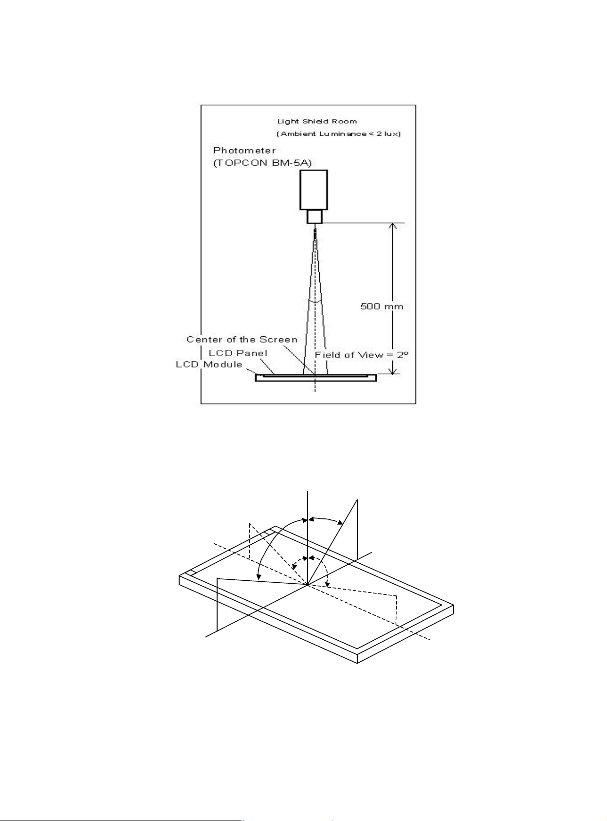
(1) Definition of Viewing Angle (θx, θy):
12 o’clock direction
6 o’clock
Normal
θX- = 90º
x-
θy- = 90º
Y-
θx = θy = 0º
θy- θy+
θx-
θx+
y+
θy+ = 90º
x+
θX+ = 90º
10
Page 11
(2) Definition of Contrast Ratio (CR):
Vertical Line
N
umber [pixel]
The contrast ratio can be calculated by the following expression and figure below.
Contrast Ratio (CR) = L255 / L0
L255: Luminance of gray level 255
L 0: Luminance of gray level 0
CR = CR (5)
CR (X) is corresponding to the Contrast Ratio of the point X at Figure in Note (5).
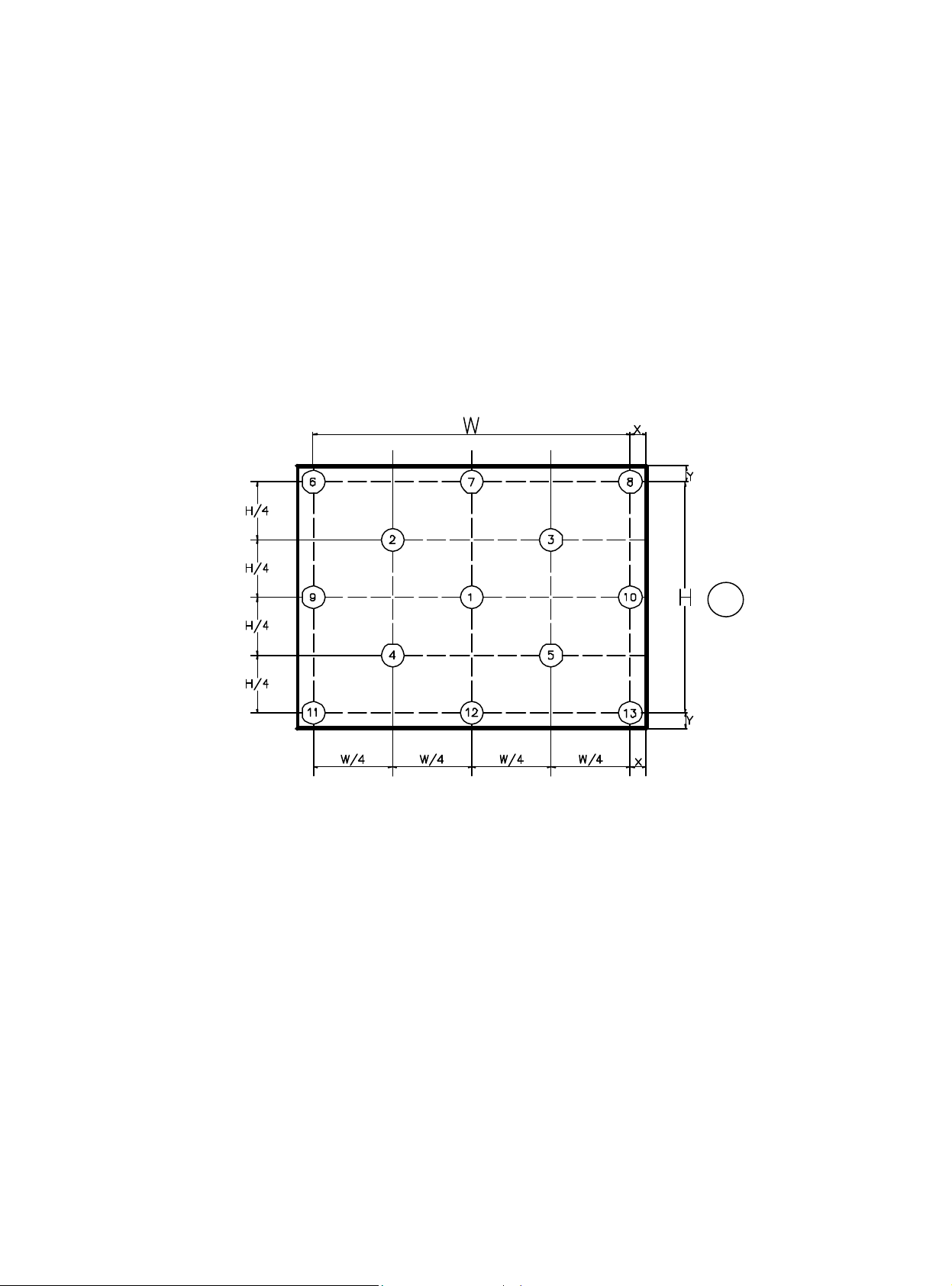
Definition of luminance measured points and Brightness Uniformity:
Horizontal Line Number [pixel]
Delta X=17.0mm;Delta Y=17.0mm。
: Test point
Active area
Luminance of center point: L= L (1)
Brightness Uniformity Measurement points: Five specified points 1-5
Formula: Maximum [L (1), L (2), L (3), L (4), L (5), L (6), L (7), L (8), L (9), L (10),
L (11), L (12), L (13)]/Minimum [L (1), L (2), L (3), L (4), L (5),
L (6), L (7), L (8), L (9), L (10), L (11), L (12), L (13)]
11
Page 12
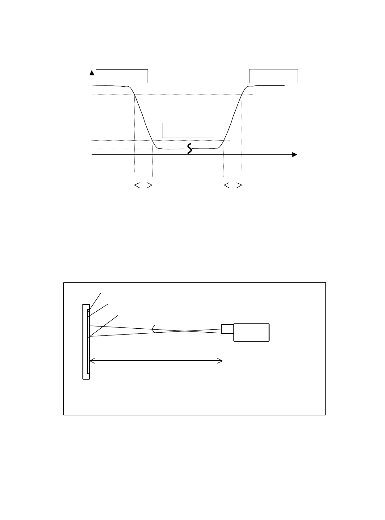
(3) Definition of Response Time (TR, TF) and Measurement Method:
Optical
100%
Light Shield Room
Gray Level 255
90%
Response
Gray Level 0
10%
0%
T
F
(4) Luminance, Chromaticity and CCT Measurement
Measurement System Setup:
The LCD module should be stabilized at given temperature for 15 minutes to avoid abrupt
temperature change during measuring. In order to stabilize the luminance, the measurement
should be executed after lighting Backlight for 15 minutes in a windless room.
LCD Module
LCD Panel
Center of the Screen
500 mm
Gray Level 255
Time
T
R
Spectrometer
(Minolta CS1000T)
(Ambient Luminance < 2 lux)
12
Page 13

OPERATING INSTRUCTIONS
2.1 Function Name
2.1.1 Front
Chapter 2
123456
No.
1 Power Switch Power On/Off
2 LED Indicator Green Normal operation
Orange Power management
3 MENU OSD control MENU button
4 > Right selection/ Volume button
5 < Left selection/ Volume button
6 AUTO Adjust Clock, Phase, H Position and V Position automatically
7 Speaker 2.5W x 2
13
Name Descriptions
77
Page 14

2.1.2 Back
12
11
10
9
8
No.
8 Lock hole Kensington
9 D-Sub D-sub mini 15pin Connector
10
11
12
Name Descriptions
DVI-D IN (Optional) 24 pin connector
Audio IN (Optional) Phone Jack 3.5ψ
AC-In AC Power Jack
14
Page 15

2.2 OSD Menu Description
<
1. Power: Press this key to control power ON/OFF of the Monitor.
Green: normal display.
Orange flicker: no signal input.
Orange: power off.
2. Auto/Exit: When the input signal source is PC, used to execute auto adjustment
3. < >: Press this button for selection or adjustment when OSD is shown.
4. +/ : Used to select the OSD function; when there is OSD menu, used to increase
function value.
Enter brightness control function directly when there is no OSD menu.
5. —/ : Used to select the OSD function; when there is OSD menu, used to decrease
function value.
Enter contract control function directly when there is no OSD menu.
6. Menu: Use to display OSD menu; when there is OSD menu, used to execute OSD
function or enter next layer of OSD menu; if executing OSD function, exit OSD
function and save the value adjusted.
AUTO
>
MENU
POWER
15
Page 16

2.3 OSD Control
Color Temp. Adjustment
OSD Setting
1. Click MENU to display the OSD window as shown in the following figure.
2. Click < or > to select the function to be adjusted as shown in the following figure.
3. Click the MENU to select the function to be adjusted.
4. Click < or > to change current settings.
5. To exit OSD, select “ ” to close the OSD window and save changes. To change
other settings, repeat steps 2-4.
2.4 OSD Menu Screen
Auto Adjustment
Message
Restore
Exit
Bright/Contract Adjust ment
Phase/Clock pulse Adjustment
Horizontal/Vertical Adjustment
Language Selection
u The OSD disappears several seconds after you stop pressing the buttons while
u Any changes are automatically saved in the memory when the OSD disappears.
16
performing an adjustment.
Turning off the power should be avoided while using the menu.
Page 17

u Adjustments for clock, phase and positions are saved for each signal timing. Except for
these adjustments, all other adjustments have only one setting, which applies to all
signal timings.
u The color will change from white to pink while the function is selected.
17
Page 18

2.5 OSD Function Definition
Secondary
Adjust the contrast between the foreground and
Adjust the focus of the image (for analog input
Adjust the clock pulse of the image (for analog input
the screen (for analog
Move the image up and down on the screen (for analog
Set up horizontal, vertical, sequence and focus
and the input port
Primary
Directory
Symbol
Directory
Symbol
N/A
N/A
N/A
N/A
N/A Deutsch
N/A
N/A
N/A
N/A
N/A 日本語
N/A
N/A
N/A
N/A
N/A
Secondary
Directory Items
Contrast
Brightness Adjust the background brightness of the screen
Phase
Clock Pulse
Horizontal
Vertical
Warm Color Temp. Set up the color temp. to be warm white color
Cold Color Temp. Set up the color temp. to be cold white color
User Definition/Red
User
Definition/Green
User
Definition/Blue
English
繁體中文
Francis
Espanola
Italian
????
Horizontal Move OSD left and right
Vertical Move OSD up and down
OSD Time Display Adjust OSD time display settings
Auto Adjustment
Analog
Digital
Message
Restore Restore to factory settings
Exit Close the OSD window and save changes
Description
background of an image on the screen
adjustment only)
adjustment only)
Move the image left and right on
input adjustment only)
input adjustment only)
Adjust red/green/blue gain
Select the language you want
automatically (for analog input only)
Select the input source you want (for DVI Input only)
Display resolution, H/V frequency
used for current input timing function
18
Page 19

2.6 Plug and Play
u The new VESA Plug and Play function is used which eliminates the complicated and
time-consuming installation process.
u You can use the Plug and Play system without encountering usual installation problems.
Your computer system can easily identify and automatically adjust the monitor.
u The LCD Monitor uses Display Data Channel (DDC) to send Extended Display
Identification Data (EDID) to the computer system, so the computer system can be set
to monitor auto adjust.
2.7 Power Saver
u Power control system, also called (Power Saver), is installed inside the LCD Monitor.
u If the monitor has not been used for a certain period of time, the system will turn the
monitor to low voltage mode to save power. Slight moving or any click will return to the
original image.
u The VGA card inside the computer handles Power Saver. You can use computer
software to set the function.
u The LCD Monitor is compatible with EPA ENERGY STAR and NÜ TEK if used with a
VESA DPMS computer.
u To save power, turn off the power of the LCD monitor when not in use.
19
Page 20

MACHINE DISASSEMBLY
AND ASSEMBLY
3.1 Disassembly Procedures
Picture Description
Chapter 3
20
Page 21

21
Page 22

22
Page 23

23
Page 24

3.2 Assembly Procedures
24
Page 25

25
Page 26

26
Page 27

27
Page 28

Troubleshooting
4.1 Abnormal Display Troubleshooting
Chapter 4
28
Page 29

29
Page 30

4.2 Abnormal (ON/OFF, LCD display, Keyboard) Troubleshooting
30
Page 31

4.3 Abnormal (BIOS, OSD, Other Display) Troubl eshooting
31
Page 32

4.4 Audio Abnormal Troubleshooting
32
Page 33

Connector Information
5.1 Function Block Diagram
Audio In
Analog Video
AC Power
D-sub
OSD Key Pad / Audio Out
DC/DC
DC-5V
Main Board
LIPS
Chapter 5
Speaker
3.3V
LCD Module
Signal
DC-19V
Backlight
33
Page 34

5.2 D-sub mini 15pin Connector
Pin No. Pin Function Pin No. Pin Function
1 Red video input 9 NC
2 Green video input 10 Ground
3 Blue video input 11 No connection
4 NC 12 (SDA)
5 Ground 13 Horizontal sync (Composite sync)
6 Red video ground 14 Vertical sync
7 Green video ground 15 (SCL)
8 Blue video ground
5.3 Audio Connector Phone Jack, d=3.5mm
5.4 AC Connector ac power jack
34
Page 35

FRU (Field Replaceable Unit) List
Chapter 6
Part List
Picture Part name Description Vendor Part
No.
35
Page 36

Picture Part name Description Vendor Part
No.
36
Page 37

37
Page 38

Explosion Diagram
38
 Loading...