


M11A System
User’s Guide

Copyright
Copyright 1996 by this company. All rights reserved. No part of
this publication may be reproduced, transmitted, transcribed, stored in
a retrieval system, or translated into any language or computer
language, in any form or by any means, electronic, mechanical,
magnetic, optical, chemical, manual or otherwise, without the prior
written permission of this company.
Disclaimer
This company makes no representations or warranties, either
expressed or implied, with respect to the contents hereof and
specifically disclaims any warranties, merchantability or fitness for
any particular purpose. Any software described in this manual is sold
or licensed "as is". Should the programs prove defective following
their purchase, the buyer (and not this company, its distributor, or its
dealer) assumes the entire cost of all necessary servicing, repair, and
any incidental or consequential damages resulting from any defect in
the software. Further, this company reserves the right to revise this
publication and to make changes from time to time in the contents
hereof without obligation to notify any person of such revision or
changes.
Intel is a registered trademark of Intel Corporation.
Pentium Pro is a trademark of Intel Corporation.
PS/2 is a trademark of International Business Machines Corporation.
Other brand and product names are trademarks and/or registered trademarks of their
respective holders.
ii

IMPORTANT SAFETY INSTRUCTIONS
1. Read these instructions carefully. Save these instructions for
future reference.
2. Follow all warnings and instructions marked on the product.
3. Unplug this product from the wall outlet before cleaning. Do not
use liquid cleaners or aerosol cleaners. Use a damp cloth for
cleaning.
4. Do not use this product near water.
5. Do not place this product on an unstable cart, stand, or table.
The product may fall, causing serious damage to the product.
6. Slots and openings in the cabinet and the back or bottom are
provided for ventilation; to ensure reliable operation of the
product and to protect it from overheating, these openings must
not be blocked or covered. The openings should never be
blocked by placing the product on a bed, sofa, rug, or other
similar surface. This product should never be placed near or
over a radiator or heat register, or in a built-in installation unless
proper ventilation is provided.
7. This product should be operated from the type of power indicated
on the marking label. If you are not sure of the type of power
available, consult your dealer or local power company.
8. This product is equipped with a 3-wire grounding-type plug, a
plug having a third (grounding) pin. This plug will only fit into a
grounding-type power outlet. This is a safety feature. If you are
unable to insert the plug into the outlet, contact your electrician
to replace your obsolete outlet. Do not defeat the purpose of the
grounding-type plug.
9. Do not allow anything to rest on the power cord. Do not locate
this product where persons will walk on the cord.
iii

10. If an extension cord is used with this product, make sure that the
total ampere rating of the equipment plugged into the extension
cord does not exceed the extension cord ampere rating. Also,
make sure that the total rating of all products plugged into the
wall outlet does not exceed 15 amperes.
11. Never push objects of any kind into this product through cabinet
slots as they may touch dangerous voltage points or short out
parts that could result in a fire or electric shock. Never spill
liquid of any kind on the product.
12. Do not attempt to service this product yourself, as opening or
removing covers may expose you to dangerous voltage points or
other risks. Refer all servicing to qualified service personnel.
13. Unplug this product from the wall outlet and refer servicing to
qualified service personnel under the following conditions:
a. When the power cord or plug is damaged or frayed
b. If liquid has been spilled into the product
c. If the product has been exposed to rain or water
d. If the product does not operate normally when the operating
instructions are followed. Adjust only those controls that are
covered by the operating instructions since improper
adjustment of other controls may result in damage and will
often require extensive work by a qualified technician to
restore the product to normal condition.
e. If the product has been dropped or the cabinet has been
damaged
f. If the product exhibits a distinct change in performance,
indicating a need for service
iv

14. Replace battery with the same type as the product's battery we
recommend. Use of another battery may present a risk of fire or
explosion. Refer battery replacement to a qualified serviceman.
15. Warning! Battery may explode if not handled properly. Do not
recharge, disassemble or dispose of in fire. Keep away from
children and dispose of used battery promptly.
16. Use only the proper type of power supply cord set (provided in
your keyboard/manual accessories box) for this unit. It should be
a detachable type: UL listed/CSA certified, type SVT/SJT, rated
6A 125V minimum, VDE approved or its equivalent. Maximum
length is 15 feet (4.6 meters).
v

FCC Class B Radio Frequency Interference
Statement
Note:
This equipment has been tested and found to comply with the limits
for a Class B digital device, pursuant to Part 15 of FCC Rules. These
limits are designed to provide reasonable protection against harmful
interference in a residential installation. This equipment generates,
uses, and can radiate radio frequency energy and, if not installed and
used in accordance with the instructions, may cause harmful
interference to radio communications. However, there is no
guarantee that interference will not occur in a particular installation. If
this equipment does cause harmful interference to radio or television
reception, which can be determined by turning the equipment off and
on, the user is encouraged to try to correct the interference by one or
more of the following measures:
1. Reorient or relocate the receiving antenna.
2. Increase the separation between the equipment and receiver.
3. Connect the equipment into an outlet on a circuit different from
that to which the receiver is connected.
4. Consult the dealer or an experienced radio/television technician
for help.
Notice 1:
The changes or modifications not expressly approved by the party
responsible for compliance could void the user's authority to operate
the equipment.
Notice 2:
Shielded interface cables, if any, must be used in order to comply
with the emission limits.
vi

About this Manual
Purpose
This user’s guide aims to give you the information you need to
operate the system properly and tells you how to install internal
components.
Manual Structure
This user’s guide consists of three chapters.
Chapter 1 System Board
This chapter describes the system board and all its major
components. It contains the system board layout, jumper
settings, cache and memory configurations, and information on
other internal devices.
Chapter 2 BIOS Utility
This chapter gives information about the system BIOS and tells
how to configure the system by changing the settings of the
BIOS parameters.
Chapter 3 System Utilities
This chapter tells how to use the AFlash BIOS Utility and the
SCSISelect Configuration Utility.
vii
Conventions
The following conventions are used in this manual:
Text entered by user Represents text input by the user.
Screen messages
, , , etc. Represent the actual keys that you
Denotes messages that appear
onscreen.
have to press on the keyboard.
NOTE
Gives bits and pieces of additional
information related to the current
topic.
WARNING
Alerts you to any damage that
might result by not following the
instructions.
CAUTION
Gives precautionary measures to
avoid possible hardware or
software problems.
IMPORTANT
Reminds you to take specific
actions relevant to the
accomplishment of procedures.
viii
TIP
Tells how to accomplish a
procedure with minimum steps
through little shortcuts.

Table of Contents
Chapter 1 System Board
1.1 Features .................................................................. 1-1
1.2 Major Components ...................................................1-2
1.2.1 System Board Layout................................1-3
1.3 Jumpers and Connectors .........................................1-4
1.3.1 Jumper and Connector Locations..............1-4
1.3.2 Jumper Settings........................................1-5
1.3.3 Connector Functions..................................1-8
1.4 ESD Precautions....................................................1-10
1.5 Installing a Pentium Pro CPU .................................1-11
1.5.1 Installation with the Sliding Heat Sink......1-11
1.5.2 Installation with the Hook-Type Heat
Sink.........................................................1-13
1.6 Memory Upgrade ...................................................1-15
1.6.1 Rules for Adding Memory........................1-15
1.6.2 Memory Configurations ...........................1-16
1.6.3 Installing a SIMM.....................................1-17
1.6.4 Removing a SIMM................................... 1-18
1.6.5 Reconfiguring the System........................1-19
1.7 SCSI Feature.........................................................1-20
1.7.1 Using the SCSI Feature...........................1-20
1.8 Server Management Features (optional)................1-21
1.8.1 ASM Pro.................................................. 1-21
1.8.2 Remote Diagnostic Management.............1-22
ix

1.9 Error Messages......................................................1-24
1.9.1 Software Error Messages........................1-24
1.9.2 System Error Messages ..........................1-24
1.9.3 Correcting Error Conditions.....................1-27
Chapter 2 BIOS Utility
2.1 Entering Setup.........................................................2-2
2.2 Basic System Configuration.....................................2-3
2.2.1 Date and Time ..........................................2-4
2.2.2 Diskette Drives..........................................2-5
2.2.3 IDE Drives.................................................2-6
2.2.4 Onboard IDE.............................................2-7
2.2.5 System Memory........................................2-8
2.2.6 Math Coprocessor.....................................2-8
2.2.7 Video Display............................................2-8
2.2.8 Communication Settings ...........................2-8
2.2.9 Enhanced IDE Features............................2-9
2.2.10 Large Memory Support Mode..................2-10
2.2.11 Num Lock After Boot...............................2-10
2.2.12 Memory Test...........................................2-10
2.2.13 Auto Configuration Mode.........................2-11
2.2.14 Fast Boot Mode.......................................2-11
2.2.15 Quiet Boot...............................................2-11
2.2.16 Configuration Table.................................2-12
2.3 Advanced System Configuration............................2-13
2.3.1 Shadow RAM..........................................2-14
2.3.2 L1 & L2 Cache (CPU Cache)...................2-14
x

2.3.3 Cache Scheme........................................2-14
2.3.4 ECC/Parity Mode Selection.....................2-15
2.3.5 Operation of ECC ....................................2-15
2.3.6 Setting for SNA Cards.............................2-16
2.3.7 Memory at 15MB-16MB...........................2-16
2.4 PCI System Configuration......................................2-17
2.4.1 PCI IRQ Setting....................................... 2-17
2.4.2 VGA Palette Snoop.................................2-19
2.4.3 Onboard SCSI .........................................2-19
2.5 Power Saving Configuration ...................................2-20
2.5.1 Power Management Mode.......................2-21
2.5.2 System Wakeup Events..........................2-21
2.6 System Security.....................................................2-22
2.6.1 Disk Drive Control...................................2-22
2.6.2 Onboard Communication Ports................ 2-24
2.6.3 Onboard PS/2 Mouse (IRQ12).................2-26
2.6.4 Setup Password.......................................2-27
2.6.5 Power On Password................................2-29
2.7 Load Setup Default Settings...................................2-30
2.8 Remote Diagnostic Configuration...........................2-30
2.9 Leaving Setup ........................................................2-31
2.10 IDE Hard Disk Types..............................................2-32
xi

Chapter 3 System Utilities
3.1 AFlash BIOS Utility..................................................3-1
3.1.1 Executing AFlash......................................3-2
3.1.2 Quick Way to Execute AFlash...................3-3
3.2 SCSISelect Configuration Utility...............................3-4
3.2.1 Overview...................................................3-4
3.2.2 Utility Options............................................3-6
3.2.3 Configuring Multiple SCSI Controllers.....3-20
3.2.4 Disk Drives Over 1 GByte.......................3-21
xii

List of Figures
1-1 System Board Layout...............................................1-3
1-2 Jumper and Connector Locations.............................1-4
1-3 USB Bracket Installation...........................................1-9
1-4 Attaching the Sliding Heat Sink to the CPU............1-11
1-5 Installing a CPU with the Sliding Heat Sink.............1-12
1-6 Installing the Hook-Type Heat Sink and Fan ...........1-13
1-7 Installing a SIMM ...................................................1-17
1-8 Removing a SIMM .................................................1-18
1-9 Installing the RDM Module .....................................1-22
1-10 Connecting the RDM Cable....................................1-23
3-1 Options Menu Screen...............................................3-6
3-2 Configure/View Host Adapter Settings Screen..........3-7
3-3 Host Adapter SCSI ID Selections .............................3-8
3-4 SCSI Parity Checking Selections..............................3-9
3-5 Host Adapter SCSI Termination .............................3-10
3-6 Boot Device Configuration......................................3-11
3-7 SCSI Device Configuration.....................................3-12
3-8 Advanced Configuration Options............................3-15
3-9 SCSI Disk Utilities Screen......................................3-18
xiii

List of Tables
1-1 Jumper Settings.......................................................1-5
1-2 CN13 Settings for CPU Core/Bus Frequency
Ratio........................................................................1-6
1-3 CN14 Settings for CPU Core Voltage.......................1-7
1-4 Connector Functions................................................1-8
1-5 Memory Configurations..........................................1-16
1-6 System Error Messages.........................................1-25
2-1 Drive Control Settings............................................2-23
2-2 Serial Port 1 Settings .............................................2-24
2-3 Serial Port 2 Settings .............................................2-24
2-4 Parallel Port Settings .............................................2-25
2-5 Parallel Port Operation Mode Settings ...................2-26
3-1 Settings for the SCSI Controller and All Devices......3-4
3-2 Individual Settings for SCSI Drives ..........................3-5
xiv

Chapter
11
System Board
1.1 Features
This high-performance system board supports the new Intel Pentium
Pro CPU running at 150/180/200 MHz. Designed to work with Intel
chipsets composed of PCI bridge, memory controller, data bus
accelerator, and data buffers, the CPU carries a new generation of
power not present in its predecessors. The CPU also incorporates the
first-level (L1) and second-level (L2) caches, the advanced peripheral
interrupt controller (APIC), and the system bus controller.
The system board utilizes both the ISA and the PCI local bus
architecture. Three ISA and four PCI bus slots reside on the board to
allow installation of either master or slave devices.
The board has three memory banks composed of two 72-pin SIMM
sockets each that support a maximum system memory of 384 MB
using 64-MB SIMMs. The SIMM sockets support both EDO and fastpage mode SIMMs.
A 50-pin Fast SCSI-II and a 68-pin Wide SCSI interface come with
the system board to connect SCSI devices. Standard I/O features
such as two enhanced IDE drive interfaces, two serial interfaces, one
parallel port interface, a diskette drive interface, and PS/2 mouse and
keyboard connectors reside on the system board.
System Board 1-1

1.2 Major Components
The system board has the following major components:
• One zero-insertion force (ZIF) socket for Intel Pentium Pro CPU
• Three memory banks (Bank 1 to Bank 3) composed of six 72-pin
SIMM sockets
• Three ISA and four PCI expansion slots
• 256-KB Flash ROM for system BIOS
• 50-pin Fast SCSI-II and 68-pin Wide SCSI interfaces
• RDM connectors (optional)
• Enhanced IDE hard disk and diskette drive interfaces
• Power connector for 200-watt switching power supply
• I/O, SCSI, and memory, controller chipsets
• ASM controller chipset (optional)
• USB interface for additional peripheral support (optional)
• External ports:
• PS/2-compatible keyboard port
• PS/2-compatible mouse port
1-2 User’s Guide

1.2.1 System Board Layout
1
5
234
967810
11121315141617
18
1 Power connector
2 Diskette drive connector
3 IDE 1 connector
4 IDE 2 connector
5 SIMM sockets
6 RDM connectors
7 CPU voltage regulators
8 VRM components
9 Pentium Pro CPU socket
10 Buzzer
11 Narrow SCSI connector
12 Wide SCSI connector
13 ISA bus slots
14 PCI slots
15 BIOS
16 Battery
17 PS/2 mouse connector
18 PS/2 keyboard connector
Figure 1-1 System Board Layout
System Board 1-3

1.3 Jumpers and Connectors
1.3.1 Jumper and Connector Locations
Figure 1-2 shows the jumper locations on the system board. The
blackened pin on a jumper represents pin 1.
Figure 1-2 Jumper and Connector Locations
The blackened pin of a jumper or connector
represents pin 1.
1-4 User’s Guide

1.3.2 Jumper Settings
Table 1-1 Jumper Settings
Jumper Setting Function
BIOS Type
J4 1-2
Password Security
J5 1-2
SCSI Selection
J6 Open
CPU Bus Frequency
J9 1-2
SCSI Termination
J10 Open
Sound Output
J13 1-2*
Reset/SMM Switch
JMP1 1-2*
*
2-3
2-3*
1-2
2-3*
1-2
2-3*
2-3
2-3
Acer BIOS
OEM BIOS
Password check
Password bypass
Narrow SCSI
Wide SCSI
60 MHz (150/180 MHz)
66 MHz (200 MHz)
Terminator off for both narrow
and wide SCSI
Terminator on for either narrow
or wide SCSI
SCSI terminator switchable to On
or Off using the SCSI setup utility
Buzzer
Speaker
Enables reset switch
Disables reset switch and
enables SMM switch
*
Default setting
System Board 1-5

Table 1-2 lists the CPU core over bus frequency ratios depending on
CN13 settings.
Table 1-2 CN13 Settings for CPU Core/Bus Frequency Ratio
CN13 Settings CPU Core /
1-5 2-6 3-7 4-8 Bus Freq. Ratio
1 1 1 1 2
1 1 0 1 3
1 1 1 0 4
1 1 0 0 5
0 1 1 1 2.5
0 1 0 1 3.5
0 = Open 1 = Closed
1-6 User’s Guide

Table 1-3 lists the CPU core voltages depending on CN14 settings.
Table 1-3 CN14 Settings for CPU Core Voltage
CN14 Settings
1-5 2-6 3-7 4-8 CPU Voltage
1 1 1 1 3.5
1 1 1 0 3.4
1 1 0 1 3.3
1 1 0 0 3.2
1 0 1 1 3.1
1 0 1 0 3.0
1 0 0 1 2.9
1 0 0 0 2.8
0 1 1 1 2.7
0 1 1 0 2.6
0 1 0 1 2.5
0 1 0 0 2.4
0 0 1 1 2.3
0 0 1 0 2.2
0 0 0 1 2.1
0 0 0 0 Reserved
0 = Open 1 = Closed
DO NOT change the settings of CN14 unless
you are qualified to do so. Ask a technician if
you need help when configuring these
jumpers.
System Board 1-7

1.3.3 Connector Functions
Table 1-4 lists the different connectors on the system board and their
respective functions.
Table 1-4 Connector Functions
Connector Function
CN1 COM1 connector
CN2 COM2 connector
CN3 Parallel port connector
CN4 Power connector
CN5 Diskette drive connector
CN6 IDE1 connector
CN7 IDE2 connector
CN8, CN9 RDM connectors
CN10 Software shutdown power control connector
CN12 Universal serial bus (USB) connector
CN15 Speaker connector
CN16 Power LED and keylock connector
CN17 Reset button and RDM cable connector
CN18 Hard disk LED connector
FA1 CPU fan connector
FA2, FA3, FA4 Reserved (for housing fans)
CNN1 Reserved
CN11 Reserved
J8 Wide SCSI connector
J12 Narrow SCSI connector
1-8 User’s Guide

USB Bracket Installation
The system board includes a connector (CN12) for the optional
universal serial bus (USB) bracket. The USB bracket has two
external special connectors to support additional serial peripherals.
The USB bracket is an optional item.
Follow these steps to install the USB bracket:
1. Remove the cover of an expansion slot on the housing rear
panel.
2. Insert the USB bracket into the slot until it fits in place.
3. Secure the bracket with a screw.
4. Locate CN12 on the system board. See Figure 1-2.
5. Attach the USB cable connector to CN12.
The USB cable is a 10-pin female connector. Note that one pin
on the connector is covered to ensure the correct orientation
when you attach it to CN12 which is an 8-pin connector.
CN12
Figure 1-3 USB Bracket Installation
System Board 1-9

1.4 ESD Precautions
Always observe the following ESD (electrostatic discharge)
precautions before installing any system component:
1. Do not remove any system component from its packaging unless
you are ready to install it.
2. Wear a wrist grounding strap before handling electronic
components. Wrist grounding straps are available at most
electronic component stores.
DO NOT attempt the procedures in the
following sections unless you are confident of
your capability to perform them. Otherwise,
ask a service technician for assistance.
1-10 User’s Guide

1.5 Installing a Pentium Pro CPU
1.5.1 Installation with the Sliding Heat Sink
Follow these installation steps if your CPU board comes with the
sliding heat sink:
1. Release the heat sink locks.
2. Attach the heat sink by sliding its rails along the longer sides of
the rectangular Pentium Pro CPU. Make sure that the heat sink
completely covers the CPU.
3. Hold the CPU and the heat sink firmly together then slide the
locks on the sides of the heat sink to secure the CPU.
STEP 1
STEP 2
STEP 3
Figure 1-4 Attaching the Sliding Heat Sink to the CPU
System Board 1-11
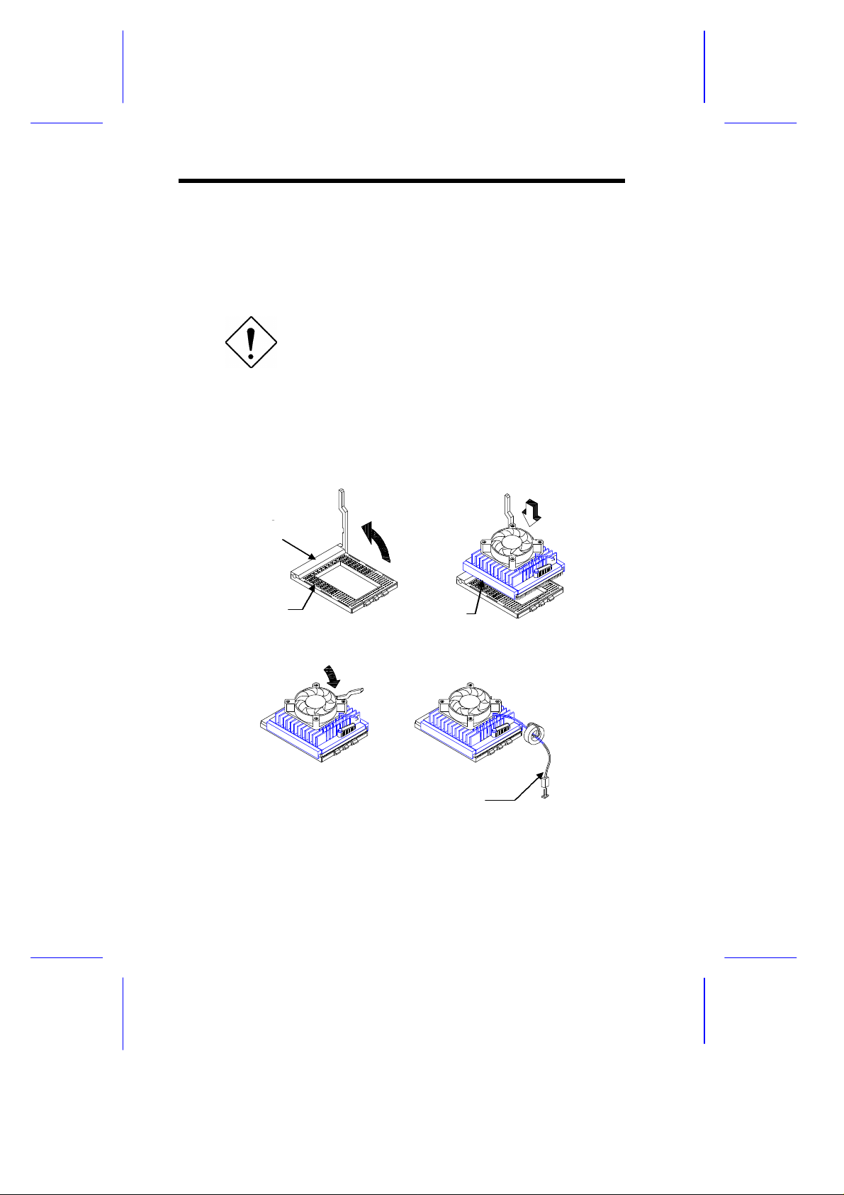
4. Lift up the CPU socket lever.
5. Look at the underside of the CPU and note the area where the
pins are denser or closely embedded. Gently insert the CPU
pins into the socket, matching the denser pins with the denser
holes on the socket.
Be careful not to bend any pins.
6. Push down the socket lever.
7. Connect the CPU fan cable to the fan connector FA1 on the
system board.
STEP 4
CPU Socket Base
Denser Holes
STEP 6
STEP 5
Denser Pins
STEP 7
Fan Cable
Figure 1-5 Installing a CPU with the Sliding Heat Sink
1-12 User’s Guide

1.5.2 Installation with the Hook-Type Heat Sink
Follow these installation steps if your CPU board comes with the
hook-type heat sink:
1. Lift up the CPU socket lever.
2. Look at the underside of the CPU and note the area where the
pins are denser or closely embedded. Gently insert the CPU
pins into the socket, matching the denser pins with the denser
holes on the socket.
3. Push down the socket lever.
4. Place the heat sink and fan over the CPU such that the rear heat
sink hook matches the holding tab on the socket base, and the
front heat sink hook (locking hook) matches the tab on the front
of the socket.
Rear Heat Sink Hook
CPU Socket Base
CPU Socket Lever
Front Heat Sink Hook (locking hook)
Figure 1-6 Installing the Hook-Type Heat Sink and Fan
System Board 1-13

5. Link the rear heat sink hook to the holding tab at the base of the
socket, then the front hook to the holding tab on the front. This
locks the heat sink and fan to the CPU socket.
To remove the heat sink and fan, simply
press the upper part of the front heat sink
hook inward.
6. Attach the CPU fan cable to the fan connector FA1 on the board.
1-14 User’s Guide

1.6 Memory Upgrade
The six 72-pin SIMM sockets onboard support both Extended Data
Output (EDO) and fast-page mode SIMMs. You may install 4-MB and
16-MB single-density as well as 8-MB, and 32-MB double-density
SIMMs for a total of 192-MB system memory. The SIMM sockets
also support 64-MB SIMMs, when available, to achieve 384-MB
system memory.
1.6.1 Rules for Adding Memory
• Use only the same type of SIMM in a given bank
• You may combine different types of SIMMs for a particular
memory configuration as long as the SIMMs in each bank are of
the same type.
• Always install SIMMs in pairs. For example, for a total memory
of 16 MB, install two 8-MB SIMMs into the sockets marked S6
and S5 (bank 1) or S2 and S1 (bank 3). You can not use a
16-MB SIMM alone for a 16-MB memory.
• Always install SIMMs starting from an inner socket. For
example, install SIMMs in socket S6 before in socket S5, or in
socket S2 before socket S1.
• Always remove SIMMs starting from an outer socket. For
example, remove SIMMs in socket S5 before in socket S6, or in
socket S1 before socket S2.
System Board 1-15

1.6.2 Memory Configurations
Table 1-5 lists the available memory configurations.
Table 1-5 Memory Configurations
Bank 1 Bank 2 Bank 3 Total
S6 S5 S4 S3 S2 S1 Memory
8 MB 8 MB 16 MB
8 MB 8 MB 4 MB 4 MB 24 MB
8 MB 8 MB 8 MB 8 MB 32 MB
16 MB 16 MB 32 MB
16 MB 16 MB 4 MB 4 MB 40 MB
16 MB 16 MB 8 MB 8 MB 48 MB
16 MB 16 MB 8 MB 8 MB 4 MB 4 MB 56 MB
8 MB 8 MB 8 MB 8 MB 16 MB 16 MB 64 MB
4 MB 4 MB 8 MB 8 MB 32 MB 32 MB 88 MB
16 MB 16 MB 16 MB 16 MB 16 MB 16 MB 96 MB
32 MB 32 MB 8 MB 8 MB 16 MB 16 MB 112 MB
32 MB 32 MB 32 MB 32 MB 128 MB
32 MB 32 MB 32 MB 32 MB 16 MB 16 MB 160 MB
32 MB 32 MB 32 MB 32 MB 32 MB 32 MB 192 MB
64 MB 64 MB 64 MB 64 MB 64 MB 64 MB 384 MB
The above configurations are only some of
the available memory combinations. You
can use other combinations as long as you
follow the rules for upgrading memory. See
section 1.6.1.
1-16 User’s Guide

1.6.3 Installing a SIMM
1
2
Follow these steps to install a SIMM:
1. Carefully slip a SIMM at a 45° angle into a socket making sure
that the curved edge indicating the pin 1 of the SIMM matches
pin 1 of the socket.
A SIMM fits only in one direction. If you slip
in a SIMM but would not completely fit, you
may have inserted it the wrong way.
Reverse the orientation of the SIMM.
2. Gently push the SIMM to a vertical position until the pegs of the
socket slip into the holes on the SIMM, and the holding clips lock
the SIMM into position. The SIMM should be at a 90° angle
when installed.
Peg
Pin 1 Indicator
(curved edge)
Hole
Figure 1-7 Installing a SIMM
System Board 1-17

1.6.4 Removing a SIMM
2
Follow these steps to remove a SIMM:
1. Press the holding clips on both sides of the SIMM outward to
release it.
2. Push the SIMM downward to a 45o angle.
3. Pull the SIMM out of the socket.
Holding Clip
1
3
Figure 1-8 Removing a SIMM
1-18 User’s Guide

1.6.5 Reconfiguring the System
Reconfigure the system after installing or removing SIMMs.
Follow these steps to reconfigure the system:
1. Reboot the system. A memory error message appears,
indicating that the total memory does not match the value stored
in CMOS.
2. Press + + during the power-on self-test (POST)
routine to run Setup. During POST, a message indicating a
wrong memory configuration appears.
3. Press twice to exit Setup and reboot the system. The
system boots with the new memory configuration.
System Board 1-19

1.7 SCSI Feature
The system board features a single-chip SCSI host adapter that adds
SCSI I/O capability to the system. The chipset consists of an onboard
microcontroller, bus master interface controller, and SCSI controllers.
A 50-pin Fast SCSI-II interface with 10 MB/s transfer rate and a
68-pin Wide SCSI interface that transfers at 20 MB/s (Wide SCSI)
and 40 MB/s (Ultra SCSI) are also onboard to accommodate various
SCSI devices.
1.7.1 Using the SCSI Feature
Follow these steps to use the SCSI feature:
1. Install a SCSI device in the system and connect it to the SCSI
interface on the system board. See Figure 1-1 for the location.
2. Set jumper J6 and J10 accordingly. Refer to Table 1-1 for the
jumper settings.
3. Enter the BIOS utility to set the corresponding SCSI parameters.
4. Enter the SCSI Configuration Utility and make the necessary
changes. Refer to Chapter 3 for information on the SCSI
Configuration Utility.
For more information about the installation procedures under different
operating systems, read the README.XXX in the subdirectory of the
target operating system.
1-20 User’s Guide

1.8 Server Management Features (optional)
1.8.1 ASM Pro
The ASM Pro is a server management tool based on the Simple
Network Management Protocol (SNMP). It detects server problems
related to the CPU thermal condition, 5V/3.3V detection, or PCI bus
utilization calculation.
This feature is designed primarily for server supervisors and
management information system (MIS) personnel to help them detect
errors or potential trouble spots in their network servers through a
single management station.
The ASM Pro consists of two major parts:
• ASM-Station - a Windows-based monitoring station that
communicates with the ASM-Agents.
• ASM-Agent(s) - the individual servers managed by the
ASM-Station.
Refer to the ASM Pro user’s manual for more information.
System Board 1-21

1.8.2 Remote Diagnostic Management
The Remote Diagnostic Management (RDM) is a network
management tool that utilizes modems and telephone lines to control
a host of servers from a remote station. It monitors and analyzes the
server condition, updates the BIOS settings if necessary, or reboots
the server in the event of failure and quickly return it to normal
operation. This capability to execute the RDM program from a
remote site bridges the distance barrier in fixing server problems and
reduces wasted time due to system failure.
Installing the RDM Module
The system board comes with connectors CN8 and CN9 to
accommodate the RDM module, and CN17 to connect the RDM
cable.
Follow these steps to install the RDM module and connect the cable:
1. See Figure 1-1 for the location of the RDM connectors.
2. Gently insert the RDM module into CN8 and CN9. The module
fits only in one direction. Do not force it into to the connectors.
CN8
CN9
1-22 User’s Guide

Figure 1-9 Installing the RDM Module
3. Insert the cable end with the RDM button into the slot on the
housing front panel.
4. Attach the other end of the RDM cable to CN17 (pins 5-6, 11-12)
on the system board. Note that the covered pin of the cable
connector does not connect to any pin.
RDM Cable
CN17
7
1
6
Figure 1-10 Connecting the RDM Cable
Refer to the RDM User’s Guide for detailed instructions on RDM
installation.
System Board 1-23

1.9 Error Messages
Do not continue using the computer if you receive an error message
of any type. Note the message and take corrective action. This
section describes the types of error messages and lists their
corresponding corrective measures.
There are two general types of error messages:
• Software
• System
1.9.1 Software Error Messages
Software error messages are returned by your operating system or
application. These messages typically occur after you boot the
operating system or when you run your application. If you receive
this type of message, consult your application or operating system
manual for help.
1.9.2 System Error Messages
A system error message indicates a problem with the computer itself.
A message of this type normally appears during the power-on selftest, before the operating system prompt appears. Table 1-6 lists the
system error messages.
1-24 User’s Guide

Table 1-6 System Error Messages
Message Action
CMOS Battery Error Replace the battery or contact
your dealer.
CMOS Checksum Error Run Setup.
CPU BIOS Update Code
Mismatch
Diskette Drive Controller Error
or Not Installed
Diskette Drive Error Check the CMOS settings in
Diskette Drive A Type
Mismatch
Diskette Drive B Type
Mismatch
Equipment Configuration
Error
Hard Disk Controller Error Run Setup.
Hard Disk 0 Error Check all cable connections.
Hard Disk 1 Error Check all cable connections.
Hard Disk 0 Extended Type
Error
Hard Disk 1 Extended Type
Error
I/O Parity Error Contact your dealer.
Keyboard Error or No
Keyboard Connected
Keyboard Interface Error Replace the keyboard or contact
Contact your dealer.
Check and connect the control
cable to the diskette controller.
Setup and the diskette drive
cable connections.
Run Setup and select the proper
drive type.
Run Setup and select the proper
drive type.
Modify DRAM configuration to
agree with one of the options in
Table 1-5.
Replace hard disk.
Replace hard disk.
Run Setup.
Run Setup.
Check and connect the keyboard
to the system unit.
your dealer.
System Board 1-25

Table 1-6 System Error Messages (continued)
Message Action
Memory Error at:
MMMM:SSSS:OOO
(W:XXXX, R:YYYY)
where:
M: MB, S: Segment,
O: Offset,
X/Y: write/read pattern
Memory Size Mismatch
CPU Clock Mismatch
Onboard Serial Port 1 Conflict Run Setup and disable the port.
Onboard Serial Port 2 Conflict Run Setup and disable the port.
Onboard Parallel Port Conflict Run Setup and disable the port.
Pointing Device Error Check and connect pointing
Pointing Device Interface
Error
Press F1 key to continue or
Ctrl-Alt-Esc for Setup
Real Time Clock Error Run Setup and set the time and
Press Esc to turn off NMI, any
key to reboot
Real-time Clock Error Run Setup.
Check SIMMs on the system
board. Contact your dealer.
Check the memory size based on
the system specifications. Check
the internal cable connections. If
you are sure that connections
and values are correct, ignore the
message. If the message
reappears, ask for technical
assistance.
device.
Replace the pointing device or
contact your dealer.
Press or
+ + to enter
Setup.
date.
Press to disregard the NMI
error.
Press any other key to reboot the
system.
1-26 User’s Guide

1.9.3 Correcting Error Conditions
As a general rule, if an error message says "Press F1 to continue," it
is caused by a configuration problem, which can be easily corrected.
An equipment malfunction is more likely to cause a fatal error, i.e., an
error that causes complete system failure.
Here are some corrective measures for error conditions:
1. Run Setup. You must know the correct configuration values for
your system before you enter Setup, which is why you should
write them down when the system is correctly configured. An
incorrect configuration is a major cause of power-on error
messages, especially for a new system.
2. Remove the system cover, following the directions in the housing
installation manual. Check that the jumpers on the system board
and any expansion boards are set correctly.
3. If you cannot access a new disk, it may be because your disk is
not properly formatted. Format the disk first using the FDISK
and FORMAT commands.
4. Check that all connectors and boards are secure.
If you go through these steps and still receive an error message, the
cause may be an equipment malfunction.
If you are sure that your configuration values are correct and your
battery is in good condition, the problem may lie in a damaged or
defective chip.
In either case, contact an authorized service center for assistance.
System Board 1-27

Chapter
22
BIOS Utility
Most systems are already configured by the manufacturer or the
dealer. There is no need to run Setup when starting the computer
unless you get a Run Setup message.
If you repeatedly receive Run Setup
messages, the battery may be bad. In this
case, the system cannot retain configuration
values in CMOS. Ask a qualified technician
for assistance.
Before you run Setup, make sure that you have saved all open files.
The system reboots immediately after you exit Setup.
BIOS Utility 2-1
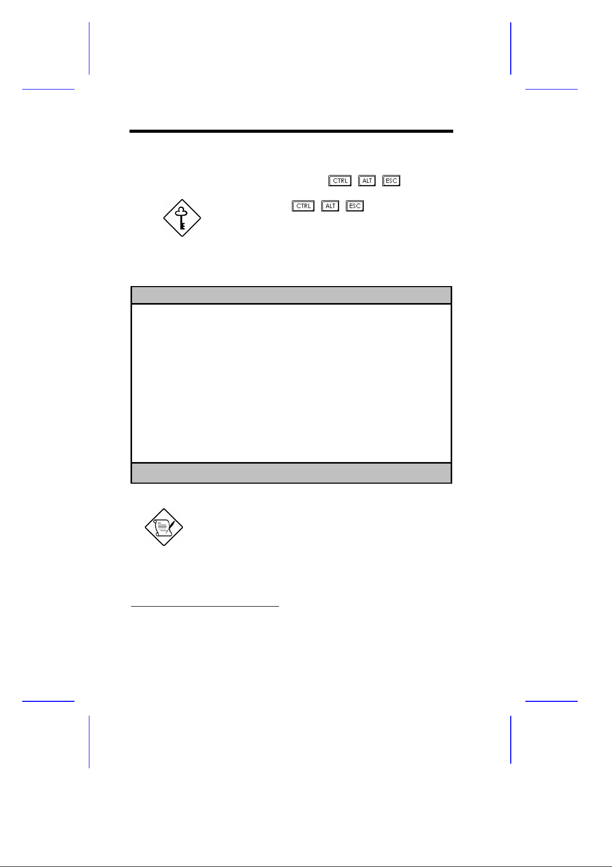
2.1 Entering Setup
To enter Setup, press the key combination + +
.
You must press + + while the
system is booting. This key combination
does not work during any other time.
The BIOS Utility main menu then appears:
BIOS Utility
Basic System Configuration
Advanced System Configuration
PCI System Configuration
Power Saving Configuration
System Security
Load Setup Default Settings
Remote Diagnostic Configuration
↑↓ = Move Highlight Bar, ↵ = Select, Esc = Exit and Reboot
1
The parameters on the following screens show
default values. These values may not be the same
as those in your system.
The grayed items (denoted with asterisks) on the
following screens have fixed settings and are
non-configurable.
1
This item appears only if an RDM module is installed in the system. Refer to the
RDM User’s Guide if your system supports this feature.
2-2 User’s Guide

2.2 Basic System Configuration
Select Basic System Configuration to input configuration values such
as date, time, and disk types.
The following screen shows the Basic System Configuration menu.
Basic System Configuration Page 1/2
Date ..................... [MM/DD/YY]
Time ..................... [HH:MM:SS]
Diskette Drive A ......... [xx-MB xx-inch]
Diskette Drive B ......... [xx-MB xx-inch]
Cylinder Head Sector
IDE Drive 0 (xxx MB)..... [Auto] xx xx xx
IDE Drive 1 (xxx MB)..... [Auto] xx xx xx
IDE Drive 2 (xxx MB)..... [Auto]
IDE Drive 3 (xxx MB)..... [Auto]
*Onboard IDE............... [Enabled ]
*Base Memory ............. [ xxx] KB
*Extended Memory ......... [ xxxx] KB
*Total Memory ............ [ xxxx] KB
*Math Coprocessor ........ [ Installed ]
*Video Display ........... [VGA/EGA]
↑↓ = Move Highlight Bar, → ← = Change Setting
PgDn/PgUp = Move Screen, F1 = Help, Esc = Exit
The command line at the bottom of the menu tells you how to
highlight items, change settings, and move from one screen to
another.
Press or on the cursor-edit keypad to highlight the desired
parameter.
Press or to select the desired option for a parameter.
Press to move to the next page or to return to the previous
page.
*
Grayed and non-configurable
BIOS Utility 2-3

Press to exit the configuration menu.
The following screen shows page 2 of the Basic System Configuration
menu.
Basic System Configuration Page 2/2
Communication Settings
Baud Rate ..................... [9600] BPS
Parity ........................ [None]
Stop Bits ..................... [1] Bits
Data Length ................... [8] Bits
Enhanced IDE Features
Hard Disk Block Mode .......... [Enabled ]
Advanced PIO Mode ............. [Enabled ]
Hard Disk Size > 504MB ........ [Enabled ]
Hard Disk 32-bit Access ....... [Enabled ]
Large Memory Support Mode ......... [ Normal ]
Num Lock After Boot .............. [Enabled ]
*Memory Test ....................... [Disabled]
Auto Configuration Mode ........... [Enabled ]
Fast Boot Mode ................... [Enabled ]
Quiet Boot ....................... [Enabled ]
Configuration Table .............. [Enabled ]
↑↓ = Move Highlight Bar, → ← = Change Setting
PgDn/PgUp = Move Screen, F1 = Help, Esc = Exit
The following sections explain the different parameters and their
settings.
2.2.1 Date and Time
The real-time clock keeps the system date and time. After setting the
date and time, you need not enter them every time you turn on the
system. As long as the internal battery remains good (approximately
seven years) and connected, the clock continues to keep the date and
time accurately even when the power is off.
*
Grayed and non-configurable
2-4 User’s Guide

Date
Highlight the items on the date parameter and press or to set
the date following the month-day-year format.
Valid values for month, day, and year are:
• Month 1 to 12
• Day 1 to 31
• Year 00 to 99
Time
Highlight the items on the time parameter and press or to set
the time following the hour-minute-second format.
Valid values for hour, minute, and second are:
• Hour 00 to 23
• Minute 00 to 59
• Second 00 to 59
2.2.2 Diskette Drives
To enter the configuration value for the first diskette drive (drive A),
highlight the Diskette Drive A parameter. Press or key to view
the options and select the appropriate value.
Possible settings for the Diskette Drive parameters:
• [ None ]
• [360 KB, 5.25-inch]
• [1.2 MB, 5.25-inch]
• [720 KB, 3.5-inch]
• [1.44 MB, 3.5-inch]
• [2.88 MB, 3.5-inch]
Follow the same procedure for Diskette Drive B. Choose None if you
do not have a second diskette drive.
BIOS Utility 2-5

2.2.3 IDE Drives
Move the highlight bar to the IDE Drive 0 parameter to configure the
first IDE drive (drive C). Press or to display the IDE hard disk
types with their respective values. Select the type that corresponds to
your drive. Follow the same procedure for the other drives, if any.
Choose None if you do not have other drives.
Selecting the “Auto” Option
If you do not know the exact type of your IDE drive, select the option
Auto. During the power-on self-test (POST), when the system
performs self-testing and self-initialization before loading the
operating system and applications, the BIOS utility automatically
determines your IDE drive type. You can see the drive type and its
values when you enter the BIOS Utility.
Cylinder Head Sector
IDE Drive 0 (xx MB) ... [Auto] xx xx xx
If desired, you can save the values under the option User.
Cylinder Head Sector
IDE Drive 0 (xx MB) ... [User] xx xx xx
The next time you boot the system, the BIOS utility does not have to
auto-configure your IDE drive as it detects the saved disk information
during POST.
We recommend that you copy the IDE disk
drive values and keep them in a safe place in
case you have to reconfigure the disk in the
future.
Follow the same procedure to auto-configure other IDE drives.
2-6 User’s Guide

Selecting the “User” Option
There are cases when you cannot use the option Auto, instead you
have to select User. Choose the User option when you have
installed an hard disk that was previously formatted but does not use
the disk native parameters or structure, that is, the disk type may be
in the hard disk types list but the number of cylinders, heads, and
sectors differ.
Follow these steps to configure a hard disk with the User option:
1. Highlight an hard disk parameter.
2. Select the option User and press .
3. Type in the number of cylinders, heads, and sectors of the drive
under the appropriate columns.
Be sure to have the correct hard disk
information beforehand.
4. Choose YES when asked if you want to save CMOS data.
2.2.4 Onboard IDE
This parameter enables or disables IDE channels 1 and 2 which
support up to two IDE drives each. The onboard IDE channel 1 uses
the system resource IRQ14 while IDE channel 2 uses IRQ15.
When set to Enabled, this parameter enables all of the IDE drives
installed in the system. Setting to Disabled deactivates the IDE
drives and grays the IDE Drive parameters.
Disabling this option frees IRQ14 and IRQ15 making them available
for add-on cards use. However, if there is no drive connected to IDE
channel 2, the system automatically frees IRQ15 for other devices
even if this parameter is enabled.
BIOS Utility 2-7

2.2.5 System Memory
The system automatically detects the total amount of onboard
memory during the POST and sets the memory parameters
accordingly. If you install additional memory, the system
automatically adjusts the Total Memory parameter to display the new
memory size.
2.2.6 Math Coprocessor
The CPU includes a math coprocessor so this parameter shows
Installed by default.
2.2.7 Video Display
The video display is the monitor on which the operating system
prompt appears when you boot the system. The system automatically
detects the video mode of your primary display and sets the
configuration value accordingly.
2.2.8 Communication Settings
The Communication Settings parameters allow you to set the baud
rate, parity, stop bit and data length for the first serial port (COM 1).
The values for this parameter are:
• Baud rate : 300 to 9600 bits per second (bps)
• Parity : odd, even, or none
• Stop bit : 1 or 2 stop bits
• Data length : 7- or 8-bit data word
The baud rate maximum value 9600 BPS
applies only to POST under UNIX
environment. The system I/O chipset
SMC 37C665 supports up to 115.2K bps.
2-8 User’s Guide

2.2.9 Enhanced IDE Features
Hard Disk Block Mode
This function enhances disk performance depending on the hard disk
in use. If you set this parameter to Enabled, it allows data transfer in
block (multiple sectors) by increasing the data transfer rate to 256
bytes per cycle. If your system does not boot after enabling this
parameter, change the setting to Disabled. This parameter is
normally set to Disabled .
Advanced PIO Mode
Enabling this parameter improves system performance by allowing
the use of faster hard drives. If your hard disk does not support this
function, set this parameter to Disabled . The default if Enabled .
Hard Disk Size > 504 MB
This enhanced IDE feature works only under DOS and Windows 3.x
environments. If enabled, it allows you to use a hard disk with a
capacity of more than 504 MB. This is made possible through the
Logical Block Address (LBA) mode translation. Other operating
systems require this parameter to be set to Disabled .
To prevent data loss, set this parameter set to Enabled if you are
using a hard disk with more than 504 MB capacity that was previously
configured through LBA mode. If you use a hard disk configured
through cylinder-head-sector (CHS) mode, set this parameter to
Disabled .
BIOS Utility 2-9

Hard Disk 32-bit Access
Enabling this parameter improves system performance by allowing
the use of the 32-bit hard disk access. This enhanced IDE feature
only works under DOS, Windows 3.x, Windows 95, and Novell
NetWare. If your software or hard disk does not support this function,
set this parameter to Disabled . The default is Enabled .
2.2.10 Large Memory Support Mode
This parameter allows the system to support an extended memory
higher than 64 MB. Set this parameter to Advanced if you are
working with Windows NT 3.1 and the system memory size is greater
than or equal to 64 MB, otherwise, set it to Normal .
2.2.11 Num Lock After Boot
This parameter allows you to activate the Num Lock function upon
booting. The default setting is Enabled.
2.2.12 Memory Test
When set to Enabled, this parameter allows the system to perform a
RAM test during the POST routine. When set to Disabled, the
system detects only the memory size and bypasses the test routine.
The default setting is Disabled .
This item is fixed to Disabled and is not user-configurable if you
enabled the Auto Configuration Mode and the Fast Boot Mode
parameters on page 2 of the Basic System Configuration menu. See
sections 2.2.13 and 2.2.14.
2-10 User’s Guide

2.2.13 Auto Configuration Mode
When enabled, this parameter automatically sets the system
configuration values to their optimized settings. At the same time, it
causes the Memory Test parameter to be fixed to Disabled and the
shadow RAM regions for system and video BIOS to Enabled . See
sections 2.2.12 and 2.3.1.
Set this parameter to Enabled if you do not know the IDE drive type
and the onboard communication port configurations.
2.2.14 Fast Boot Mode
When enabled, this parameter allows the system to boot faster by
skipping some POST routines. It bypasses memory test, enables
Shadow RAM, and enables primary- and second-level cache.
When set to Enabled, this parameter causes the Memory Test
parameter to be fixed to Disabled and the shadow RAM regions for
system and video BIOS to Enabled . See sections 2.2.12 and 2.3.1.
2.2.15 Quiet Boot
This parameter enables or disables the quiet boot function. When set
to Enabled, BIOS is in graphical mode and displays only an
identification logo during POST and while booting. After which the
screen displays the operating system prompt (such as DOS) or logo
(such as Windows 95). If any error occurred while booting, the
system automatically switches to the text mode.
Even if your setting is Enabled, you may also switch to the text mode
while booting by pressing after you hear a beep that indicates the
activation of the keyboard.
When set to Disabled, BIOS is in the conventional text mode where
you see the system initialization details on the screen.
BIOS Utility 2-11

2.2.16 Configuration Table
This parameter allows you to display the configuration table after
POST but before booting. The configuration table gives a summary
of the hardware devices and settings that BIOS detected during
POST. Following is a sample configuration table.
CPU/CLK : Pentium Pro/xxx MHz
Math Coprocessor: Installed
IDE Drive 0 : xxx MB
IDE Drive 1 : xxx MB
IDE Drive 2 : xxx MB
IDE Drive 3 : xxx MB
Diskette Drive A: xx-MB, xx-inch
Diskette Drive B: None
Base Memory: : xxx KB
Extended Memory: xxxx KB
Shadow RAM : xxx KB
Internal Cache : xxx KB, Enabled
External Cache : xxx KB, Enabled
Serial Port(s) : 3F8h, 2F8h
Parallel Port : 378h
Pointing Device: None
2-12 User’s Guide

2.3 Advanced System Configuration
The Advanced System Configuration option allows you to configure
the advanced system memory functions.
Do not change any settings in the Advanced
Configuration if you are not a qualified
technician to avoid damaging system.
The following screen shows page one of the Advanced System
Configuration parameters.
Advanced System Configuration Page 1/1
Shadow RAM
*E0000h - FFFFFh (System BIOS) ... [Enabled ]
*C0000h - C7FFFh (Video BIOS) ..... [Enabled ]
C8000h - CBFFFh ................. [Disabled]
CC000h - CFFFFh ................. [Disabled]
D0000h - D3FFFh .................. [Disabled]
D4000h - D7FFFh ................. [Disabled]
D8000h - DBFFFh ................. [Disabled]
DC000h - DFFFFh ................. [Disabled]
L1 & L2 Cache (CPU Cache) ........... [Enabled ]
Cache Scheme ......................... [Write through]
ECC/Parity Mode Selection ........... [ ECC ]
Operation of ECC ..................... [Correction Enabled ]
Setting for SNA Cards ............... [Disabled]
Memory at 15MB-16MB Reserved for ..... [ System ] Use
↑↓ = Move Highlight Bar, → ← = Change Setting
PgDn/PgUp = Move Screen, F1 = Help, Esc = Exit
*
Grayed and non-configurable
BIOS Utility 2-13

2.3.1 Shadow RAM
The system reserves 384 KB of random access memory (RAM) for
the shadow RAM function. This parameter has eight range
addresses. When you set these addresses to Enabled, the system
BIOS, video BIOS, and I/O ROM functions run directly from the
shadow RAM for faster operation. When you set them to Disabled,
the functions run normally from ROM.
The address range E0000h - FFFFFh is for shadowing the system
BIOS. This item is always set to Enabled and is not userconfigurable. The address range C0000h - C7FFFh is for shadowing
the video BIOS. This item is fixed to Enabled and is not userconfigurable if the Auto Configuration Mode and the Fast Boot Mode
parameters on page 2 of the Basic System Configuration menu are
enabled. Otherwise, you can disable this item.
The remaining address ranges are for I/O ROM functions.
2.3.2 L1 & L2 Cache (CPU Cache)
This parameter enables or disables the first- and second-level cache
memory integrated in the Pentium Pro CPU. This item is fixed to
Enabled and is non-configurable if you enabled the Auto
configuration Mode and Fast Boot Mode parameters on page 2 of the
Basic System Configuration menu. Otherwise, you can disable this
item.
2.3.3 Cache Scheme
This parameter allows you to select Write back or Write through
for the cache mode. Write back updates the cache but not the
memory when there is a write instruction. It updates the memory only
when there is an inconsistency between the cache and the memory.
Write through updates both the cache and the memory whenever
there is a write instruction.
2-14 User’s Guide

2.3.4 ECC/Parity Mode Selection
This parameter allows you to select ECC, Parity, or Disabled . The
ECC option allows single-bit error detection and automatic correction.
The automatic correction depends on the setting of the parameter
Operation of ECC. See section 2.3.5 for details.
ECC also detects multiple-bit errors but does not correct them.
Instead, it issues a non-maskable interrupt (NMI) signaling the
operating system of the multiple-bit error detection.
The Parity option allows parity check. If it detects any parity errors,
it sets up the parity error flag in the chipset. This signals the
operating system of the parity error detection.
Fast-page mode SIMMs with parity support both ECC and parity
mode. EDO SIMMs with parity support only ECC mode.
Both the ECC and parity check features
require parity SIMMs. You must disable this
parameter if you installed SIMMs without
parity.
2.3.5 Operation of ECC
This parameter allows you to enable or disable the error correction
function. In the option Correction Enabled, ECC automatically
corrects any single-bit errors detected. For multiple-bit errors
detected, ECC only issues an NMI to signal the operating system of
the multiple-bit error detection.
In the option Correction Disabled, ECC detects both single-bit
and multiple-bit errors but does not correct either one. It only issues
an NMI to signal the operating system of the error detection.
This parameter is grayed if the ECC/Parity Mode Selection parameter
is set to either Parity or Disabled . Refer to section 2.3.4.
BIOS Utility 2-15

2.3.6 Setting for SNA Cards
System network architecture (SNA) cards are 8-bit IBM-compatible
network cards. Should you need to install an SNA card, make sure to
set this parameter to Enabled .
2.3.7 Memory at 15MB-16MB
To prevent memory address conflicts between the system and
expansion boards, reserve this memory range for the use of either the
system or an expansion board. Before setting this parameter, check
your add-on card manual to determine if your add-on card needs this
memory space. If not, set this parameter to System Use.
2-16 User’s Guide

2.4 PCI System Configuration
The PCI System Configuration allows you to specify the settings for
your PCI devices.
PCI System Configuration Page 1/1
PCI IRQ Setting ........... [ Auto ]
*PCI Slot 1............ [--] [--] [--] [--]
*PCI Slot 2 ........... [--] [--] [--] [--]
*PCI Slot 3 ........... [--] [--] [--] [--]
*PCI Slot 4 ........... [--] [--] [--] [--]
*Onboard SCSI ......... [--]
VGA Palette Snoop ......... [Disabled]
Onboard SCSI .............. [Enabled ]
Boot Device ........... [Disabled]
↑↓ = Move Highlight Bar, → ← = Change Setting
PgDn/PgUp = Move Screen, F1 = Help, Esc = Exit
2.4.1 PCI IRQ Setting
INTA INTB INTC INTD
This parameter allows for Auto or Manual configuration of PCI
devices. If you use plug-and-play (PnP) devices, set this parameter
to Auto. The system then automatically assigns IRQ to the PnP
devices. If your PCI device is not a PnP, you can manually assign
the interrupt for each device. Refer to your manual for technical
information about the PCI card.
When the PCI IRQ Setting is set to Auto, all
the IRQ setting fields become gray and nonconfigurable.
*
Grayed and non-configurable
BIOS Utility 2-17

PCI Slots
These parameters allow you to specify the appropriate interrupt for
each of the PCI devices. You can assign IRQ3, IRQ4, IRQ5, IRQ7,
IRQ9, IRQ10, IRQ11, IRQ12, IRQ14, or IRQ15 to the slots.
The items PCI Slot 4 and Onboard SCSI share the same IRQ.
Setting an interrupt for the former automatically sets that same
interrupt for the latter.
Make sure that the interrupt you assign in
any of the PCI slots are not used by other
devices to avoid conflicts.
Press or to move between fields. Press or to select
options.
Onboard SCSI
This item allows you to manually assign the interrupt for the onboard
SCSI hard disk when the PCI IRQ Setting parameter is set to Manual
. This parameter is grayed and not user-configurable when the PCI
IRQ Setting is set to Auto and when the Onboard SCSI parameter is
set to Disabled . See sections 2.4.1 and 2.4.3.
Make sure to assign an IRQ to this item if
you set the PCI IRQ Setting parameter to
Manual.
Press or to move between fields. Press or to select
options.
2-18 User’s Guide

2.4.2 VGA Palette Snoop
This parameter permits you to use the palette snooping feature if you
installed more than one VGA card in the system.
The VGA palette snoop function allows the control palette
register (CPR) to manage and update the VGA RAM DAC (Digital
Analog Converter, a color data storage) of each VGA card installed in
the system. The snooping process lets the CPR send a signal to all
the VGA cards so that they can update their individual RAM DACs.
The signal go through the cards continuously until all RAM DAC data
have been updated. This allows display of multiple images on the
screen.
Some VGA cards have required settings for
this feature. Check your VGA card manual
before setting this parameter.
2.4.3 Onboard SCSI
This parameter allows you to enable or disable the SCSI feature.
Setting this parameter to Enabled and assigning it an IRQ causes the
corresponding IRQ in the Power Saving Configuration screen to be
set to Enabled as well. The particular IRQ setting turns gray and
non-configurable.
Boot Device
This parameter allows you to enable or disable the onboard SCSI
boot priority.
BIOS Utility 2-19

2.5 Power Saving Configuration
The Power Saving Configuration parameters are configurable only if
your system supports the power management feature.
The following screens show the Power Saving Configuration
parameters and their default settings:
Power Saving Configuration Page 1/1
Power Management Mode ................[Enabled ]
IDE Hard Disk Standby Timer .......[15] Minutes
System Suspend Timer ..............[15] Minutes
System Wakeup Events
IRQ 0...... [Disabled]* IRQ 8...... [Disabled]
IRQ 1...... [Enabled ]* IRQ 9...... [Disabled]
IRQ 3...... [Disabled] IRQ 10..... [Disabled]
IRQ 4...... [Disabled] IRQ 11..... [Disabled]
IRQ 5...... [Disabled] IRQ 12..... [Enabled ]*
IRQ 6...... [Enabled ] IRQ 13..... [Enabled ]
IRQ 7...... [Disabled] IRQ 14..... [Enabled ]
↑↓ = Move Highlight Bar, → ← = Change Setting
PgDn/PgUp = Move Screen, F1 = Help, Esc = Exit
IRQ 15..... [Disabled]
*
Grayed and non-configurable
2-20 User’s Guide

2.5.1 Power Management Mode
This parameter allows you to reduce power consumption. When this
parameter is set to Enabled, you can configure the system timers.
Setting to Disabled deactivates the power management feature and
all the timers.
For system models with RDM module
installed, enabling the RDM feature disables
the power management parameters.
IDE Hard Disk Standby Timer
This parameter allows the hard disk to enter standby mode after
inactivity of 1 to 15 minutes, depending on your setting. When you
access the hard disk again, allow 3 to 5 seconds (depending on the
hard disk) for the disk to return to the normal speed. Set this
parameter to Off if your hard disk does not support this function.
System Suspend Timer
This parameter sets the system to a "fast-on" power saving mode. It
automatically enters the standby mode after a specified period of
inactivity. Any keyboard or mouse action, or any enabled monitored
activities occurring through the IRQ channels, resume system
operation. See section 2.5.2.
2.5.2 System Wakeup Events
This parameter allows you to monitor system activities occurring
through the IRQ and determine whether or not to enter power saving
mode.
For example, if you assign IRQ3 to a fax/modem and you set this
item to Enabled, any fax/modem activity wakes up the system from
suspend mode.
BIOS Utility 2-21

2.6 System Security
The Setup program has a number of security features to prevent
unauthorized access to the system and its data.
Enter the Setup program and select System Security to display the
following screen.
System Security Page 1/1
Disk Drive Control
Diskette Drive.................. [ Normal ]
Hard Disk Drive................. [ Normal ]
System Boot Drive............... [Drive A then C]
Boot from CD-ROM................ [Disabled]
Onboard Communication Ports
Serial Port 1 Base Address...... [ 3F8h ]
Serial Port 2 Base Address...... [ 2F8h ]
Parallel Port Base Address...... [378 (IRQ 7]
Operation Mode...............[Standard Parallel Port (SPP)] Mode
*ECP DMA Channel ......... [-]
Onboard PS/2 Mouse (IRQ12) ... [Enabled ]
Setup Password .................... [ None ]
Power On Password ................. [ None ]
↑↓ = Move Highlight Bar, → ← = Change Setting
PgDn/PgUp = Move Screen, F1 = Help, Esc = Exit
2.6.1 Disk Drive Control
The disk drive control features allow you to enable or disable the
read/write functions of a disk drive. These features can also control
the diskette drive or the hard disk drive boot function to prevent
loading operating systems or other programs from a certain drive
while the other drives are operational.
Table 2-1 lists the drive control settings and their corresponding
functions.
2-22 User’s Guide

Table 2-1 Drive Control Settings
Diskette Drive
Setting Description
Normal Diskette drive functions normally
Write Protect All Sectors Disables the write function on all sectors
Write Protect Boot Sector Disables the write function only on the boot
Disabled Disables all diskette functions
Hard Disk Drive
Setting Description
Normal Hard disk drive functions normally
Write Protect All Sectors Disables the write function on all sectors
Write Protect Boot Sector Disables the write function only on the boot
Disabled Disables all hard disk functions
System Boot Drive
Setting Description
Drive A then C The system checks drive A first. If there is a
Drive C then A The system checks drive C first. If there is a
C: The system always boots from drive C.
A: The system always boots from drive A.
Boot from CD-ROM
Setting Description
Enabled The system looks for a bootable CD in the CD-
Disabled System boots from the drive specified in the
sector
sector
diskette in the drive, the system boots from drive
A. Otherwise, it boots from drive C.
hard disk (drive C) installed, the system boots
from drive C. Otherwise, it boots from drive A.
ROM. If a CD is present, the system boots
from the CD-ROM. Otherwise, it boots from the
drive specified in the System Boot drive
parameter.
System Boot Drive parameter.
BIOS Utility 2-23

2.6.2 Onboard Communication Ports
Serial Port 1 Base Address
This parameter allows you to set the serial port 1 logical base
address.
Table 2-2 Serial Port 1 Settings
Setting Description
3F8h Serial port 1 with address 3F8h using IRQ4
2F8h Serial port 1 with address 2F8h using IRQ3
3E8h Serial port 1 with address 3E8h using IRQ4
2E8h Serial port 1 with address 2E8h using IRQ3
Disabled Disables serial port 1
Serial Port 2 Base Address
This parameter allows you to set the serial port 2 logical base
address.
Table 2-3 Serial Port 2 Settings
Setting Description
3F8h Serial port 2 with address 3F8h using IRQ4
2F8h Serial port 2 with address 2F8h using IRQ3
3E8h Serial port 2 with address 3E8h using IRQ4
2E8h Serial port 2 with address 2E8h using IRQ3
Disabled Disables serial port 2
If you assign 3F8h to serial port 1, you may
only assign 2F8h or 2E8h to serial port 2.
If you assign 2F8h to serial port 1, you may
2-24 User’s Guide

only assign 3F8h or 3E8h to serial port 2.
Parallel Port Base Address
The system has one parallel port. Table 2-4 lists the options for
selecting the parallel port address. You also have the option to
disable the parallel port.
Table 2-4 Parallel Port Settings
Setting Function
3BCh (IRQ 7) Corresponds to the parallel port with
address 3BCh
378h (IRQ 7) Corresponds to the parallel port with
address 378h
278h (IRQ 5) Corresponds to the parallel port with
address 278h
Disabled Disables the parallel port
To deactivate the parallel port, select the Disabled option. If you
install an add-on card with a parallel port whose address conflicts with
the onboard parallel port, the system automatically disables the
onboard functions.
Check the parallel port address on the add-on card and change the
address to one that does not conflict.
BIOS Utility 2-25

OPERATION MODE
This item allows you to set the operation mode of the parallel port.
Table 2-5 lists the different operation modes.
Table 2-5 Parallel Port Operation Mode Settings
Setting Function
Standard Parallel Port (SPP) Allows normal speed one-way
operation
Standard and Bidirectional Allows normal speed operation in
a two-way mode
Enhanced Parallel Port (EPP) Allows bidirectional parallel port
operation at maximum speed
Extended Capabilities Port
(ECP)
ECP DMA CHANNEL
Allows parallel port to operate in
bidirectional mode and at a speed
higher than the maximum data
transfer rate
This item becomes active only if you select Extended
Capabilities Port (ECP) as the operation mode. It allows you to
select DMA channel 1 or DMA channel 3 depending on the available
system resource.
2.6.3 Onboard PS/2 Mouse (IRQ12)
This parameter enables or disables the onboard PS/2 mouse. When
set to Enabled, it allows you to use the onboard PS/2 mouse
assigned with IRQ12. When set to Disabled, it deactivates the
mouse and frees IRQ12 for the use of other devices.
2-26 User’s Guide

2.6.4 Setup Password
The setup password prevents unauthorized access to the BIOS utility.
Setting a Setup Password
1. Make sure that jumper JP5 is set to pins 2-3 (bypass).
You cannot enter the BIOS utility if a setup
password does not exist and jumper JP5 is
set to pins 1-2 (check).
The jumper JP5 is set to pins 2-3 (bypass) by
default.
2. Enter BIOS utility and select System Security.
3. Highlight the Setup Password parameter and press the or
key. The password prompt appears:
4. Type a password. The password may consist of up to seven
characters.
Be very careful when typing your password
because the characters do not appear on the
screen.
5. Press . A prompt asks you to retype the password to verify
your first entry.
6. Retype the password then press .
After setting the password, the system automatically sets the
Setup Password parameter to Present.
BIOS Utility 2-27

7. Press to exit the System Security screen and return to the
main menu.
8. Press to exit the BIOS utility. A dialog box appears asking if
you want to save the CMOS data.
9. Select Yes to save the changes and reboot the system.
10. While rebooting, turn off the system then open the housing.
11. Set jumper JP5 to pins 1-2 to enable the password function.
The next time you want to enter the BIOS utility, you must key-in your
Setup password.
Changing or Removing the Setup Password
Should you want to change your setup password, do the following:
1. Enter the BIOS utility and select System Security.
2. Highlight the Setup Password parameter.
3. Press the or key to display the password prompt and keyin a new password.
or
Press the or key and select None to remove the existing
password.
4. Press to exit the System Security screen and return to the
main menu.
5. Press to exit the BIOS utility. A dialog box appears asking if
you want to save the CMOS data.
6. Select Yes to save the changes and reboot the system.
2-28 User’s Guide

Bypassing the Setup Password
If you forget your setup password, you can bypass the password
security feature by hardware. Follow these steps to bypass the
password:
1. Turn off and unplug the system.
2. Open the system housing and set JP5 to pins 2-3 to bypass the
password checking.
3. Turn on the system and enter the BIOS utility. This time the
system does not require you to type in a password.
You can either change the existing Setup
password or remove it by selecting None.
Refer to the previous section for the
procedure.
2.6.5 Power On Password
The power on password secures your system against unauthorized
use. Once you set this password, you have to type it whenever you
boot the system.
To set a power on password, highlight the Power On Password
parameter and follow the same procedure as in setting a setup
password. See section 2.6.4.
BIOS Utility 2-29

2.7 Load Setup Default Settings
Use this option to load the default settings for the optimized system
configuration. When you load the default settings, some of the
parameters are grayed-out with their fixed settings. These grayed
parameters are not user-configurable. If you want to change the
settings of these items, disable the Fast Boot Mode parameter in the
Basic System Configuration menu.
The following dialog box appears when you select Load Setup Default
Settings from the main menu.
Load Setup Default Settings
Are you sure
[Yes] [No]
Select [Yes] to load the default settings.
2.8 Remote Diagnostic Configuration
The Remote Diagnostic Configuration allow you to set the remote
diagnostic management (RDM) parameters. This option appears on
the main screen of the BIOS Utility only when there is an RDM
module installed in the system.
Refer to the RDM User’s Guide for information if your system
supports this feature.
2-30 User’s Guide

2.9 Leaving Setup
Examine the system configuration values. When you are satisfied
that all the values are correct, write them down. Store the recorded
values in a safe place. In the future, if the battery loses power or the
CMOS chip is damaged, you will know what values to enter when you
rerun Setup.
Press to leave the system configuration setup. If there is any
change in the BIOS utility functions, the following screen appears:
Do you want to save CMOS data?
[Yes] [No]
Use the arrow keys to select your response. Select Yes to store the
new data in CMOS. Select No to retain the old configuration values.
Press .
BIOS Utility 2-31

2.10 IDE Hard Disk Types
Type Cylinders Heads Sectors Per Track
None (indicates SCSI or no hard disk)
1 306 4 17
2 615 4 17
3 615 6 17
4 940 8 17
5 940 6 17
6 615 4 17
7 462 8 17
8 733 5 17
9 900 15 17
10 820 3 17
11 855 5 17
12 855 7 17
13 306 8 17
14 733 7 17
15 (reserved)
16 612 4 17
17 977 5 17
18 977 7 17
19 1024 7 17
20 733 5 17
21 733 7 17
22 733 5 17
23 306 4 17
24 612 4 17
25 306 4 17
26 612 4 17
27 698 7 17
2-32 User’s Guide

Type Cylinders Heads Sectors Per Track
28 976 5 17
29 306 4 17
30 611 4 17
31 732 7 17
32 1023 5 17
33 751 8 17
34 755 16 17
35 731 13 26
36 980 15 17
37 936 16 17
38 981 5 17
39 981 10 17
40 762 8 39
41 980 5 17
42 832 8 33
43 683 12 38
44 513 16 38
45 776 8 33
46 683 16 38
47 832 6 33
48 615 2 34
49 989 16 63
50 823 4 38
51 1001 15 17
52 1024 17 22
53 723 13 51
54 548 8 38
55 1013 4 41
56 929 15 17
BIOS Utility 2-33

Type Cylinders Heads Sectors Per Track
57 817 14 36
58 723 13 81
59 802 4 39
60 1024 9 17
61 895 5 55
62 (reserved)
63 966 10 34
64 1024 8 17
65 1024 11 17
66 918 11 17
67 969 14 49
68 1024 10 17
69 1024 12 17
70 1024 13 17
71 1024 14 17
72 959 11 50
73 1024 16 17
74 918 15 17
75 1010 16 51
76 1024 5 17
77 1024 8 17
78 (reserved)
79 1001 15 32
80 1024 16 63
81 1024 7 17
82 988 16 52
83 1024 15 17
84 776 8 33
85 926 13 17
2-34 User’s Guide

Type Cylinders Heads Sectors Per Track
86 805 4 26
87 976 5 17
88 685 16 38
89 1011 15 22
90 997 10 53
91 985 13 32
92 816 15 32
93 968 5 17
94 903 8 46
95 966 5 34
96 535 10 50
97 715 10 50
98 1016 16 63
99 996 16 63
Auto
User
BIOS Utility 2-35

Chapter
33
System Utilities
This chapter contains information about system utilities that you need
when you upgrade your system. These utilities are the AFlash BIOS
Utility and SCSISelect Configuration Utility.
The AFlash BIOS Utility diskette does not
come with the system package. Ask your
dealer for assistance if you need the utility.
3.1 AFlash BIOS Utility
Do not install memory-related drivers (XMS,
EMS, DPMI) when you use AFlash.
The AFlash functions support all the operations required for system
Flash ROM. The functions are divided into four steps as follows.
1. Load BIOS file to buffer reads a specified file from a diskette to
memory for future program use or for check only. It supports the
64-KB, 128-KB, 192-KB, or 256-KB files.
2. Save BIOS to disk file reads BIOS from the current BIOS area
and writes to the file specified by the user.
3. Edit OEM string reads specified file from a diskette to memory,
edits OEM string and writes to a file.
System Utilities 3-1

4. Program flash memory programs Flash memory according to
the data loaded in step 1. This function also shows the BIOS
checksum and BIOS type to make sure that the operation is
correct.
AFlash features password security to prevent
unauthorized access.
3.1.1 Executing AFlash
Follow these steps to execute AFlash:
1. Copy the MSG.DAT and AFLASH.EXE files from the system
utilities diskette into the subdirectory of your choice.
2. From that subdirectory, type:
aflash
3. A help message appears. Press any key to continue.
4. The main menu appears. Use the or key to highlight the
options. Press to select.
5. If you want to save a copy of the current BIOS into a file, select
Save BIOS to Disk File.
6. Select Load BIOS File to load the BIOS file into memory.
3-2 User’s Guide

7. Select Program Flash Memory to erase the current BIOS, and
program Flash ROM.
Never turn off the system power while Flash
BIOS is programming. This will destroy the
BIOS.
8. Reboot the system.
3.1.2 Quick Way to Execute AFlash
When you have already copied the AFlash files into your hard disk,
you can simply type the following on the DOS prompt (subdirectory
where the files are located) to quickly execute the program.
aflash (filename)
The program automatically performs the loading and programming
functions, then reboots the system.
If the program cannot find the BIOS file, it returns to the main menu
and flashes the following message:
Can't Read This File !!! Press any key to continue...
In this case, follow the procedures for loading and programming the
BIOS file using the main menu.
System Utilities 3-3

3.2 SCSISelect Configuration Utility
The SCSISelect utility allows you to change SCSI controller settings
without opening the system or changing jumpers.
3.2.1 Overview
Default Values
Table 3-1 lists the settings that you can change using the SCSISelect
utility and the default value for each setting. Some settings apply
globally to the SCSI controller and all SCSI devices on the bus.
Other settings apply individually to each device on the bus.
Table 3-1 Settings for the SCSI Controller and All Devices
Item Default
Host Adapter SCSI ID 7
SCSI Parity Checking Enabled
Host Adapter SCSI Termination Enabled
Low OFF/High ON
Boot Device Option 0 (zero)
Host Adapter BIOS
Support Removable Disks under BIOS as Hard Disks Boot only
Extended BIOS Translation for DOS Drives > 1 GB Enabled
Display <Ctrl-A> Message During BIOS Initialization Enabled
Multiple Lun Support Disabled
BIOS Support for Bootable CD-ROM Enabled
BIOS Support for Int13 Extensions Enabled
Support for Ultra SCSI Speed Disabled
1
Enabled
1
The settings are valid only if the host adapter BIOS is enabled.
3-4 User’s Guide

Table 3-2 Individual Settings for SCSI Drives
Item Default
Initiate Sync Negotiation Yes
Maximum Sync Transfer Rate 20 MB/sec.
Enable Disconnection Yes
Send Start Unit SCSI Command
Initiate Wide Negotiation Yes
1
No
When to Use the SCSISelect Utility
Use the SCSISelect utility if you need to do either one of the
following:
• Change any of the default values listed in Table 3-1.
• Check and/or change SCSI device settings that may conflict with
those of other devices
• Perform low-level formatting on new SCSI disk devices
Running the SCSISelect Utility
A screen message giving the option to access the SCSISelect utility
appears after the BIOS and POST routine.
To start SCSISelect, press +A when the following message
appears during power on or system reset:
Press <Ctrl> <A> for SCSISelect Utility!
1
The settings are valid only if the host adapter BIOS is enabled.
System Utilities 3-5

Your screen may show the key sequence as
+<Hot Key> instead of +A. The
correct sequence is +A.
3.2.2 Utility Options
When the SCSISelect utility detects that AIC-7880 SCSI controller in
the system, it displays the following Options menu.
Figure 3-1 Options Menu Screen
Use the and keys and press to make selections in the
SCSISelect utility. Press at any time to return to the previous
menu.
You can press to toggle the display
between color and monochrome modes.
This feature may not work with some kinds of
monitors.
3-6 User’s Guide

Configure/View Host Adapter Settings Menu
The Configure/View Host Adapter Settings menu lists three settings
under SCSI Bus Interface Definitions and three additional options.
Figure 3-2 Configure/View Host Adapter Settings Screen
Use the and keys to select a parameter. Press to display
a pop-up menu with a list of possible settings for the parameter.
Press at any time to return to the previous menu.
Press to reset all settings to the SCSI
controller defaults. SCSI controller default
settings are marked with an asterisk (*)
throughout the selection submenus.
System Utilities 3-7

HOST ADAPTER SCSI ID
This parameter allows you to change the host controller SCSI ID.
Figure 3-3 shows the available IDS for use with the AIC-7880. The
default setting is SCSI ID 7, which has the highest priority on the
SCSI bus. We recommend that you keep the default setting since
most system applications run only in this setting.
Figure 3-3 Host Adapter SCSI ID Selections
Each device on the SCSI bus, including the SCSI controller, must be
set to a unique SCSI ID. The SCSI ID serves two purposes. It
uniquely identifies each SCSI device on the bus, and it determines
the device’s priority on the bus during the arbitration phase. The
arbitration phase determines which device controls the bus when two
or more devices request for the use of it.
Use the or keys then press to select the SCSI ID if you
need to change it. Press at anytime to return to the previous
menu.
3-8 User’s Guide

SCSI PARITY CHECKING
Select this option to enable or disable the SCSI parity checking
function on the SCSI controller. Figure 3-4 displays the selections.
The default setting is Enabled .
Figure 3-4 SCSI Parity Checking Selections
The SCSI controller always checks parity when reading from the
SCSI bus to verify the correct transmission of data from the SCSI
devices. You should disable the SCSI Parity Checking parameter if
any of the installed SCSI devices does not support SCSI parity. Most
currently available SCSI devices support this feature.
Use the or keys then press to select options. Press
at anytime to return to the previous menu.
System Utilities 3-9

HOST ADAPTER SCSI TERMINATION
This parameter allows you to configure the host controller SCSI
termination function. Figure 3-5 shows the possible settings. The
default setting is Low OFF/High ON.
Figure 3-5 Host Adapter SCSI Termination
Use the or keys then press to make a selection. Press
at anytime to return to the previous menu.
If the AIC-7880 is not at one end of the SCSI
cable, the terminating resistors located on
the system board must be disabled by setting
the SCSI terminator to Low OFF/High OFF.
See Figure 3-5. The three resistors are in
the SIP packages installed in the sockets.
3-10 User’s Guide

BOOT DEVICE OPTIONS
This parameter shows the target ID of your boot device. The default
setting is 0 (zero). We recommend that you keep the default setting
since most system applications run only in this setting. Figure 3-6
shows the boot device configuration menu.
Figure 3-6 Boot Device Configuration
System Utilities 3-11

SCSI DEVICE CONFIGURATION
This parameter allows you to configure details of each SCSI device
on the SCSI bus. A screen similar to Figure 4-7 appears. The screen
shows a column of information for each SCSI ID, even if some SCSI
IDs are not assigned to a device. To configure a specific SCSI
device, you need to know which SCSI ID it uses. See the SCSI Disk
Utilities later in this section for instructions on how to determine the
SCSI ID used by a device.
Figure 3-7 SCSI Device Configuration
Use the or keys to move between options, then press to
display a pop-up menu with a list of values.
Use the or keys to select a value, then press .
3-12 User’s Guide

Initiate Sync Negotiation
This option determines whether the SCSI controller initiates
synchronous negotiation with the SCSI device.
When set to Yes, the SCSI controller initiates synchronous
negotiation with the SCSI device. When set to No, the SCSI
controller does not initiate synchronous negotiation. The SCSI
controller, however, always responds to synchronous negotiation if
the SCSI device initiates it. The default setting is Yes.
Data is transferred in asynchronous mode if neither the SCSI
controller nor the SCSI peripheral negotiates for synchronous data
transfers.
Some older SCSI-1 devices do not support
synchronous negotiation. This may cause the
system to operate erratically or hang when the
Initiate Sync Negotiation is enabled. Set this
item to No if you installed SCSI-1 devices.
Maximum Sync Transfer Rate
This option determines the maximum synchronous data transfer rate
that the SCSI controller can support. The SCSI controller supports
rates up to the Fast Wide SCSI maximum of 20.0 MB per second.
The default value is 20.0.
In most cases, you can use the maximum value of 20.0. However, if
the SCSI controller is not set to negotiate data transfer (i.e., Initiate
Sync Negotiation is set to No), the value selected here is the
maximum rate that the SCSI controller accepts from the device
during negotiation. This is a standard SCSI protocol.
Some older SCSI-1 devices do not support Fast
SCSI data transfer rates 10.0, 8.0, and 6.7.
This may cause the system to operate
erratically or hang if the transfer rate is too high.
Select a Maximum Sync Transfer Rate of 5.0
for these devices.
System Utilities 3-13

Enable Disconnection
This option determines whether the SCSI controller allows a SCSI
device to disconnect from the SCSI bus (sometimes called
Disconnect/Reconnect). Disconnect/Reconnect allows the SCSI
controller to perform other operations on the SCSI bus while the SCSI
device is temporarily disconnected.
When set to Yes, the SCSI device may disconnect from the SCSI
bus. The SCSI device, however, may choose not to disconnect, even
if permitted by the SCSI controller. When set to No, the SCSI device
is not allowed to disconnect from the SCSI bus. The default setting is
Yes.
Keep this item set to Yes if two or more SCSI devices are connected
to the SCI controller. This optimizes SCSI bus performance. If only
one SCSI device is connected to the SCSI controller, set this item to
No to achieve better system performance.
Initiate Wide Negotiation
This option allows communication between all devices (lower 8-bit or
upper 8-bit) on the wide (16-bit) SCSI bus. When set to Yes, each
device can connect on the bus. When set to No (disabled),
communication can only occur on the lower eight bits of the 16-bit
SCSI bus. The default setting is Yes.
Send Start Unit Command
This option determines whether the Start Unit Command (SCSI
command 1B) is sent to the SCSI device (most devices do not require
this). Enabling this item reduces the load on the system power supply
by allowing the SCSI controller to power-up SCSI devices one at a
time upon booting. Otherwise, all the devices power up at the same
time. Most devices require you to set a jumper before they can
respond to this command.
3-14 User’s Guide

When set to Yes, the Start Unit Command is sent to the SCSI device
at system boot. When set to No, each SCSI device powers-up in the
normal procedure.
The Send Start Unit Command setting is
valid only if the host adapter BIOS is
enabled.
If this option is enabled for more than one SCSI device, the Start Unit
Command is sent first to the device with the lowest SCSI ID. When
this device responds to the SCSI controller, the Start Unit Command
is sent to the next highest SCSI ID with a setting of Yes. The process
continues until all supported devices respond to the SCSI controller.
If many drives are set to Yes for Send Start Unit Command, the boot
time varies depending on how long it takes each drive to spin up.
ADVANCED CONFIGURATION OPTIONS
Selecting the Advanced Configuration Options displays a screen as in
Figure 3–8. Do not change the settings of the items under this
parameter unless it is absolutely necessary.
Figure 3-8 Advanced Configuration Options
System Utilities 3-15

Use the or keys to move between options, then press to
display a pop-up menu with a list of options.
Use the or keys to select an option, then press .
Host Adapter BIOS
This option enables or disables the SCSI controller BIOS. The
default setting is Enabled .
The SCSI controller BIOS must be enabled if you want the system to
boot from a SCSI hard disk drive connected to the SCIS controller.
Several SCSISelect options cannot be used unless the SCSI
controller BIOS is enabled.
Support Removable Disks Under BIOS as Fixed Disks
This option allows you to control which removable-media drives are
supported by the SCSI controller BIOS. This is only valid when the
SCSI controller BIOS is enabled. The default setting is Boot Only.
The following choices are available:
• Boot Only - Only the removable-media drive designated as the
boot device are treated as a hard disk drive.
• All Disks - All removable-media drives supported by the BIOS
are treated as hard disk drives.
• Disabled - No removable-media drives are treated as hard disk
drives. In this case, software drivers are needed because the
drives are not controlled by BIOS.
Support for removable-media drives means that the SCSI controller
BIOS allows use of a removable-media drive as if it is a hard disk
drive. It does not mean that you can remove the disk media during
operation.
If a removable-media SCSI device is
controlled by the SCSI controller BIOS, do not
remove the media while the drive is poweredon or you may lose data!.
3-16 User’s Guide

Extended BIOS Translation fro DOS Drives > 1 GByte
This option allows you to enable or disable extended translation for
SCSI hard disks with a capacity greater then 1 GB. This is valid only
if the SCSI controller BIOS is enabled. The default factory setting is
Enabled .
When enabled, this options use the following translation schemes:
• SCSI hard disks < 1 GB use a translation scheme of 64 heads,
32 sectors per track
• SCSI hard disks > 1 GB use a translation scheme of 255 heads,
63 sectors per track
See the section Disk Drives Over 1 GB in this chapter, for more
information on this option. This option should be left disabled for
most operating systems except DOS.
Display <Ctrl-A> Message During BIOS Initialization
This option allows entering the SCSISelect utility during BIOS
initialization. The default setting is Enabled .
Multiple Lun Support
This option allows access to multiple logical unit numbers (Lun) per
SCSI ID, The default setting is Disabled.
BIOS Support for Bootable CD-ROM
When enabled, this option allows you to use a bootable CD-ROM
device to directly load an operating system. The default setting is
Enabled .
BIOS Support for Int13 Extensions
This option allows access to attached SCSI devices through BIOS
Int13 functions. The default setting is Enabled .
System Utilities 3-17

Support for Ultra SCSI Speed
This option enables wide SCSI data transfers at 40 MB per second.
Most hard disk drives or other SCSI devices do not currently support
a communication rate this high. If enabled, make sure that the device
you installed is capable of running at this rate. The default setting is
Disabled .
SCSI Disk Utilities
When you select SCSI Disk Utilities from the Options menu, the
SCSISelect Utility scans the SCSI bus and lists all SCSI devices
installed on the SCSI bus. The list shows the individual SCSI IDs
assigned to each device on the SCSI bus.
Figure 3-9 SCSI Disk Utilities Screen
Select a disk device to display a small menu window. From this
menu, select Format Disk or Verify Media.
3-18 User’s Guide

Use the or keys to move between options, then press to
display a pop-up menu with a list of values.
Use the or keys to select a value, then press .
FORMAT DISK
The Format Disk utility performs a low-level format on disk devices.
Most SCSI disk devices are preformatted and do not need to be
formatted again. The Adaptec Format Disk utility is compatible with
the vast majority of SCSI disk drives. Run it on hard disk drives or
removable-media drives that were previously used with a nonAdaptec SCSI controller.
A low-level format destroys all data on the
drive. Be sure to back up your data before
performing this operation. You cannot abort a
low-level format once it is started.
VERIFY MEDIA
The Verify Media utility scans the selected device’s media for defects.
If the utility finds bad blocks, it prompts you to reassign them. If you
select Yes, those blocks will no longer be used.
You can press at any time to abort the
Verify Disk Media utility.
System Utilities 3-19

3.2.3 Configuring Multiple SCSI Controllers
The following procedure uses AHA2940/W/UW SCSI controller as an example.
Follow these steps to configure multiple SCSI controllers:
1. Install the boot SCSI controller in the lowest PCI Device number.
The Device number is determined by the slot number on the PCI
bus.
a. To find out the Device number of the AHA-2940 SCSI
controller(s), run the SCSISelect utility by pressing the key
combination +A at power on.
b. On the first screen of SCSISelect, look for the following on
the upper right hand corner.
Bus:Device xx:xxxh (given in hexadecimal)
c. If the device number is high, move the AHA-2940 to a PCI
slot at the other end of the system board then rerun
SCSISelect to see if the number is lower.
Step 1.3 is a recommended solution for most
PCI systems. You can move the AHA-2940
SCSI controller to another PCI slot if the boot
order is not what is desired.
d. Refer to your system documentation for further details on
determining the PCI slot number and slot number order in
the system.
2. If you are booting from the AHA-2940 and using ISA/EISA-based
host adapters as secondary devices, you must disable the BIOS
on all ISA/EISA-based SCSI controllers.
3-20 User’s Guide

3. If you are booting from ISA/EISA-based controllers and using
AHA-2940 as a secondary device, see your ISA.EISA-based
SCSI controller documentation to ensure that the SCSI controller
is at the lowest BIOS base address. ISA/EISA-based SCSI
controllers with their BIOS enabled boot before the AHA-2940.
3.2.4 Disk Drives Over 1 GByte
Extended Translation
Adaptec SCSI controller have always supported the full range of disk
drive capacities under all major operating systems. As disk drives
have recently grown beyond 1 GB in formatted capacity, they have
run up against the DOS 1024-cylinder limit.
To continue its support for all SCSI disk drive capacities under DOS,
Adaptec has included an extended translation scheme for the
AIC-7880 SCSI controllers. This feature supports disk drives of up to
8 GB capacity under DOS. The section Extended BIOS Translation
for DOS Drives > 1 GB explains how to change the setting of this
option. Most operating systems leave this option disabled.
DOS 1 GByte Limit
All current versions of DOS are limited to 1024 cylinders per drive.
The standard translation scheme for SCSI host controllers, using 64
heads and 32 sectors, gives a maximum capacity of 1 GB.
To eliminate the 1-GB limit, Adaptec’s extended translation feature
uses 255 heads and 63 sectors, extending the disk drive capacity limit
under DOS to 8 GB.
If you have already partitioned a large hard
disk drive with one translation method,
conversion to another method erases the data
on the drive. Be sure to back up your disk
drive prior to any change in the translation
method.
System Utilities 3-21

When to Use the Extended Translation
WITH DOS 5.0 AND ABOVE
NetWare 386 (version 3.0 and above) and the version of UNIX do
not share the 1024 cylinder limit of DOS and do not require extended
translation to support large disk drives and should not be enabled.
DRIVES WITH MIXED PARTITIONS
Use standard translation (not extended translation) on drive formatted
with two or more partitions for different operating systems. Partitions
for UNIX and NetWare can be larger than 1 GB when using standard
translation.
The term UNIX, as used here includes all
version of AT&T/USL UNIX, SCO v3.2.4 (or
later), and ISC v3.0 (or later).
USING FDISK
TO install a new disk, or to re-partition an existing disk, use the
FDISK DOS utility as you normally would. The cylinder size
increases to 8 MB when you enable extended translation. The size of
the partition you request must therefore be a multiple of 8 MB. If you
request a partition size that is not a multiple of 8 MB, FDISK rounds
up to the nearest whole multiple of 8 MB.
3-22 User’s Guide
 Loading...