

Page 1

|
Acer | HDS WMS100
User and Reference Guide
MK-95DF738-01
Page 2

Page 3

2005 Hitachi Data Systems Corporation, ALL RIGHTS RESERVED
Notice: No part of this publication may be reproduced or transmitted in any form or by any
electronic or mechanical means, including photocopying and recording, or sto red in a
database or retrieval system for any purpose without the express written permis sion of
Hitachi Data Systems Corporation (hereinafter referred to as “Hitachi Data Systems”).
Hitachi Data Systems reserves the right to make changes to this document at any time
without notice and assumes no responsibility for its use. Hitachi Data Systems products and
services can only be ordered under the terms and conditions of Hitachi Data Systems’
applicable agreements. All of the features described in this document may not be currently
available. Refer to the most recent product announcement or contact your local Hitachi
Data Systems sales office for information on feature and product ava ilability.
This document contains the most current information available at the time of publication.
When new and/or revised information becomes available, this entire document will be
updated and distributed to all registered users.
Trademarks
Hitachi Data Systems is a registered trademark and service mark of Hitachi, Ltd., and the
Hitachi Data Systems design mark is a trademark and service mark of Hitachi, Ltd.
Egenera and BladeFrame are registered trademarks of Egenera, Inc.
Emulex is a registered trademark of Emulex Corporation.
HP-UX, MC/ServiceGuard, and Tru64 are trademarks or registered trademarks of the
Hewlett-Packard Development Company, L.P.
AIX and RS/6000 are registered trademarks of International Business Machines Corporation.
Pentium is a registered trademark of Intel Corporation.
Linux is a registered trademark of Linus Torvalds.
Microsoft, Windows, and Windows NT are registered trademarks of Microsoft Corporation.
Netscape and Netscape Navigator are registered trademarks of Netscape Communications
Corporation in the U.S. and other countries.
NetWare is a registered trademark of Novell, Incorporated.
Oracle is a registered trademark of Oracle Corporation.
QLogic is a registered trademark of QLogic Corporation.
Java, Solaris, Sun, Sun Enterprise, and Sun Fire are trademarks of Sun Microsystems, Inc.
VERITAS is a trademark of VERITAS Software Corp.
Acer | HDS WMS100™ User and Reference Guide iii
Page 4

All other brand or product names are or may be registered trademarks, trademarks, or
service marks of and are used to identify products or services of their respective owners.
Notice of Export Controls
Export of technical data contained in this document may require an export license from the
United States government and/or the government of Japan. Please contact the Hitachi Data
Systems Legal Department for any export compliance questions.
Document Revision Level
Revision Date Description
MK-95DF713-00 September 2005 Initial Release
MK-95DF713-01 November 2005 Revision 1, supersedes and replaces MK-95DF738-00
Source Document(s) for this Revision
SANRISE AMS100 (Workgroup Modular Storage) Series Disk Array Subsystem User’s Guide,
RSD-95DF738-03
Changes in this Revision
Added an introductory paragraph and table to the introduction of Chapter 1
Changed section 1.1
Changed section 1.1.2
Changed section 1.2
Added an introductory paragraph and table to the introduction of Chapter 2
Changed section 2.2.3.1
Changed section 2.4.6
Added Figure 2.4
Added Table 2.5
Changed Table 2.6
Changed Table 2.7
Changed Table 2.11
Changed Table 2.13
Changed Table 2.14
Added an introductory paragraph and table to the introduction of Chapter 3
Changed section 3.1.1
iv Preface
Page 5

Added section 3.1.3
Added an introductory paragraph and table to the introduction of Chapter 4
Changed section 4.2
Changed section 4.3
Changed section 4.3.1
Changed section 4.3.3
Changed section 4.3.4
Added section 4.4
Changed section 4.6.3
Added section 4.6.3.3
Changed section 4.6.4
Changed Figure 4.1
Added Figure 4.2
Changed Figure 4.3
Changed Figure 4.4
Changed Figure 4.5
Changed Figure 4.6
Changed Figure 4.7
Changed Figure 4.8
Changed Figure 4.11
Changed Figure 4.19
Changed Figure 4.20
Changed Figure 4.27
Changed Table 4.3
Changed Table 4.4
Changed Table 4.6
Changed Table 4.13
Added an introductory paragraph and table to the introduction of Chapter 5
Changed section 5.1
Added an introductory paragraph and table to the introduction of Chapter 6
Changed section 6.2
Added an introductory paragraph and table to the introduction of Chapter 7
Changed section 7.3.4
Acer | HDS WMS100™ User and Reference Guide v
Page 6

Changed section 7.3.6
Changed section 7.4
Changed section 7.8
Changed section 7.9
Added section 7.12
Added section 7.13
Added section 7.14
Added Figure 7.3
Added Figure 7.6
Added an introductory paragraph and table to the introduction of Chapter 8
Changed section 8.1
Changed section 8.1.1
Changed section 8.1.2
Changed section 8.1.3
Changed section 8.1.5
Changed section 8.3.1
Added section 8.3.7
Added section 8.5
Added section 8.6
Changed Figure 8.2
Added Figure 8.3
Changed Figure 8.4
Changed Figure 8.5
Changed Figure 8.7
Changed Figure 8.11
Changed Figure 8.12
Changed Table 8.5
Changed Table 8.11
vi Preface
Page 7

Added an introductory paragraph and table to the introduction of the Appendices
Changed Table C.2
Added section D.2
Changed Table E.1
Changed Figure E.1
Changed Figure J.1
Added Figure J.2
Acer | HDS WMS100™ User and Reference Guide vii
viii Preface
Page 8

Page 9

Preface
This document describes the physical, functional, and operat ional characteristics of the
WMS100 subsystem. This document also provides operation instructions, installation details,
and configuration planning information for the WMS100 subsystem .
This User and Reference Guide assumes:
The user is familiar with the Acer | HDS AMS200/WMS100™ array subsystem, and
The user is familiar with the Windows
This subsystem complies with FDA radiation performance standards 21CFR, subchapter J.
Notes:
For further information, please contact your Hitachi Data Systems account team, or visit
®
95, Windows® 98, Windows® 2000, or
Windows NT
®
operating systems. These versions are abbreviated to Windows in this
document.
the Hitachi Data Systems worldwide web site at http://www.hds.com
.
The use of Acer | HDS WMS100 subsystem and all other Acer | HDS products is governed
by the terms of your agreement(s) with Acer | HDS.
Software Version
This document revision applies to Acer | HDS AMS Products versi on 2.0 and higher.
EMI Regulation
This equipment has been tested and found to comply with the limits for a Class A digital
device, pursuant to Part 15 of the FCC Rules. These limits are designed to provide
reasonable protection against harmful interference when the equipment is operated in a
commercial environment. This equipment generates, uses, and can radiate rad io frequency
energy and, if not installed and used in accordance with the instruction manual, may cau se
harmful interference in which case the user will be required to correct the interference at
his own expense. Testing was done with shielded cables. Therefore, in order to comply with
the FCC regulations, you must use shielded cables with you installation.
Acer | HDS WMS100™ User and Reference Guide ix
Page 10

If trouble occurs in a different configuration, the user may be requested to take appropriate
preventive measures. The EMI test was done in the following configuration:
WMS100-RKXS+H1J
WMS100-RKXS+RKAJAT+H2J
Convention for Storage Capacity Values
This document uses the following convention for storage capacity values:
1 KB (kilobyte) = 1,000 bytes
1 MB (megabyte) = 1,000,000 bytes
1 GB (gigabyte) = 1,000,000,000 bytes
1 TB (terabyte) = 1,000 Gbytes
Referenced Documents
Acer | HDS AMS Cache Residency Manager Software User’s Guid
Acer | HDS Adaptable Modular Storage Storage Navigator Modular Graphical User Interface
(GUI) User’s Guide, MK-95DF711
Hitachi TagmaStore™ Adaptable Modular Storage Storage Navigator Modul ar Command Line
Interface (CLI), MK-95DF712
Hitachi TagmaStore™ Adaptable Modular Storage ShadowImage™ In-System Replication
Software User’s Guide, MK-95DF709
Hitachi TagmaStore™ Adaptable Modular Storage TrueCopy™ Synchronous Remote
Replication Software User’s Guide, MK-95DF710
Hitachi TagmaStore™ Adaptable Modular Storage Copy-on-Write SnapShot User’s Guide,
MK-95DF708
Acer | HDS Global 19-Inch Rack Reference Guide
Hitachi TagmaStore™ Adaptable Modular Storage Performance Monitor Software User’s
Guide, MK-95DF706
x Preface
Page 11

Comments
Please send us your comments on this document. Make sure to include the document title,
number, and revision. Please refer to specific section(s) and paragraph(s) whenever possible.
E-mail: doc.comments@hds.com
Fax: 858-695-1186
Mail:
Technical Writing, M/S 35-10
Hitachi Data Systems
10277 Scripps Ranch Blvd.
San Diego, CA 92131
Thank you! (All comments become the property of Hitachi Data Systems Corporation.)
Acer | HDS WMS100™ User and Reference Guide xi
xii Preface
Page 12

Page 13

Contents
Chapter 1 Overview of the WMS100 Subsystem...................................................................................1
1.1 Overview Features ...............................................................................2
1.1.1 High Data Availability...................................................................2
1.1.2 Connectivity..............................................................................2
1.1.3 Scalability ................................................................................3
1.1.4 Performance Reporting and Monitoring..............................................3
1.1.5 Reliability, Availability, and Serviceability ......................................... 4
1.2 Rack-Mount Model................................................................................5
1.3 Floor Model........................................................................................6
Chapter 2 Planning for Installation and Operation................................................................................7
2.1 User Responsibilities .............................................................................9
2.2 Safety Precautions ............................................................................. 10
2.2.1 Warning Labels......................................................................... 11
2.2.2 Repair, Modification, and Disassembly............................................. 11
2.2.3 Precautions for Using Equipment ................................................... 11
2.2.4 Inspection and Cleaning Precautions............................................... 15
2.2.5 Emergency Precautions............................................................... 16
2.2.6 Warning Notices ....................................................................... 17
2.2.7 Warning Label Locations ............................................................. 17
2.3 General Specifications and Requirements.................................................. 23
2.3.1 Dimensions and Weigh................................................................ 23
2.3.2 Service Clearance Requirements.................................................... 25
2.3.3 Floor Load Rating...................................................................... 26
2.3.4 Internal Logic Specifications......................................................... 27
2.3.5 Cable Function......................................................................... 27
2.4 Environmental Specifications and Requirements.......................................... 28
2.4.1 Environmental Hazards............................................................... 28
2.4.2 Temperature and Humidity Requirements ........................................ 29
2.4.3 Input Power and Insulation Performance Specifications........................ 29
2.4.4 Air Flow Requirements ............................................................... 30
2.4.5 Vibration and Shock Tolerances..................................................... 31
2.4.6 Reliability............................................................................... 32
Chapter 3 Powering On/Off Procedure.................................................................................................35
3.1 WMS100 Rack-Mount Model ................................................................... 36
3.1.1 Subsystem Power On.................................................................. 36
3.1.2 Subsystem Power Off ................................................................. 38
3.1.3 Stop/Start/Restart of the NAS OS .................................................. 38
3.2 WMS100 Floor Model ........................................................................... 40
3.2.1 Subsystem Power On.................................................................. 40
3.2.2 Subsystem Power Off ................................................................. 41
Chapter 4 Subsystem Architecture and Components........................................................................43
4.1 Configuration Block Diagrams ................................................................ 44
4.1.1 WMS100 Rack -Mount Model.......................................................... 44
Acer | HDS WMS100™ User and Reference Guide xiii
Page 14

4.1.2 WMS100 Floor Model.................................................................. 49
4.2 Redundant Power Supplies.................................................................... 53
4.3 Fibre Channel Interface ....................................................................... 54
4.3.1 Mini-HUB 54
4.3.2 Connection Specifications............................................................ 55
4.3.3 Fibre Channel Configuration......................................................... 57
4.3.4 Attention to the Host Direct Connection for WMS100........................... 57
4.4 Ethernet Interface.............................................................................. 58
4.5 Array Frame ..................................................................................... 58
4.5.1 WMS100 Rack -Mount Model.......................................................... 59
4.5.2 Floor Model............................................................................. 60
4.6 Component Names, Locations, and Functions ............................................. 61
4.6.1 Front Bezel Component Locations and Functions................................ 62
4.6.2 Component Locations................................................................. 64
4.6.3 Switch Locations and Functions..................................................... 65
4.6.4 Connector Locations and Functions ................................................ 67
4.6.5 LED Locations and Functions ........................................................ 70
Chapter 5 Functional and Operational Characteristics ......................................................................79
5.1 New WMS100 Features and Capabilities .................................................... 81
5.2 RAID Implementations ......................................................................... 82
5.3 Cache Management............................................................................. 84
5.4 Logical Units (LUs).............................................................................. 86
5.5 Open Systems Features and Functions ...................................................... 88
5.5.1 Open Systems Middleware ........................................................... 88
5.5.2 LUN Management...................................................................... 88
5.6 Data Management Features and Functions ................................................. 89
5.6.1 Cache Residency Manager Function ................................................ 89
5.6.2 LUN Manager Function................................................................ 89
5.6.3 Data Retention Utility Function..................................................... 89
5.6.4 LUN Expansion Function.............................................................. 89
5.6.5 Password Protection Function....................................................... 89
5.7 Copy Solution Features and Functions ...................................................... 90
5.7.1 ShadowImage In-System Replication Function.................................... 90
5.7.2 Copy-On-Write Snapshot Function.................................................. 90
5.7.3 NAS Backup Restore Modular Function............................................. 90
5.7.4 NAS SyncImage Modular Function................................................... 90
5.8 Performance Management Features and Functions....................................... 91
5.8.1 Performance Monitor Function...................................................... 91
5.8.2 Cache Partition Manager Function.................................................. 91
5.9 NAS Features and Functions .................................................................. 92
5.9.1 NAS Data Con trol Modular Function................................................ 92
5.9.2 NAS File Sharing Modular Function ................................................. 92
5.9.3 NAS Manager Modular Function ..................................................... 92
5.9.4 NAS Backup Restore Modular Function............................................. 92
5.9.5 NAS SyncImage Modular Function................................................... 92
5.9.6 NAS Anti-Virus Agent Modular Function............................................ 92
xiv Contents
Page 15

Chapter 6 Configuring the WMS100 Subsystem.................................................................................93
6.1 Overview of Configuration .................................................................... 95
6.1.1 Open Systems Configuration......................................................... 95
6.1.2 Defining LUNs.......................................................................... 95
6.1.3 Fibre Channel Interface Addressing ................................................ 96
6.1.4 Alternate Pathing...................................................................... 98
6.1.5 NAS Configuration..................................................................... 99
6.2 Configuring LAN Interfaces of the WMS100 Subsystem .................................. 100
6.3 Configuring the WMS100 Subsystem ........................................................ 101
6.4 Registering the WMS100 Subsystem for Control by Storage Navigator Modular ..... 102
6.5 Configuring the WMS100 Subsystem for the Desired Application ......................103
6.6 WMS100 Subsystem General Configuration................................................104
Chapter 7 Configuring Storage on the WMS100 Subsystem............................................................105
7.1 Software Composition ........................................................................ 107
7.1.1 Microprogram ......................................................................... 107
7.1.2 System Parameters................................................................... 107
7.1.3 Configuration Information ..........................................................107
7.1.4 SNMP Information ....................................................................107
7.1.5 Storage for Parameters.............................................................. 108
7.2 Setting Fibre Channel Information.......................................................... 109
7.3 Determining Space and RAID Level Requirements........................................111
7.3.1 Setting a Spare Disk.................................................................. 112
7.3.2 Canceling a Spare Disk Setting ..................................................... 115
7.3.3 Setting a RAID Group.................................................................116
7.3.4 Deleting a RAID Group............................................................... 119
7.3.5 Setting a Logical Unit................................................................121
7.3.6 Deleting the Last Logical Unit...................................................... 123
7.3.7 Formatting a Logical Unit........................................................... 125
7.3.8 Changing the Format Mode ......................................................... 129
7.3.9 Changing the Default Controller in Charge of an LU............................131
7.4 Setting Host Group Information.............................................................132
7.4.1 Setting Mapping Information ....................................................... 132
7.5 Transferring Configurations from One Array to Another ................................ 136
7.6 Storing Configuration Data................................................................... 137
7.6.1 System Parameter Information.....................................................137
7.6.2 RAID Group/LU information ........................................................ 138
7.6.3 Port/Host Group Informat ion.......................................................140
7.6.4 NAS System LU/User LU information.............................................. 141
7.7 Applying Configuration Data to Another WMS100 Subsystem........................... 142
7.7.1 System Parameters................................................................... 142
7.7.2 RAID Group/Logical unit.............................................................143
7.7.3 Port/Host Group......................................................................144
7.8 Setting Host Connection Parameters.......................................................145
7.8.1 Simple Setting ........................................................................ 145
7.8.2 Detailed Setting ......................................................................150
7.9 Setting the Subsystem when using Special Mode......................................... 151
7.10 Changing the Network Parameter...........................................................153
7.11 Setting the System LU and User LU in the NAS System..................................155
Acer | HDS WMS100™ User and Reference Guide xv
Page 16

7.11.1 Setting the System LU ...............................................................155
7.11.2 Setting the User LU ..................................................................157
7.12 Setting the System LU and User LU in the NAS System..................................159
7.12.1 Setting the System LU ...............................................................160
7.12.2 Setting the User LU ..................................................................162
7.13 Setting the NNC Management LAN Port Information in the NAS System..............164
7.14 Setting the Time Zone........................................................................167
Chapter 8 Troubleshooting.................................................................................................................171
8.1 Troubleshooting Based on LED Indications ................................................ 173
8.1.1 The POWER LED Does Not Turn On ................................................ 173
8.1.2 The POWER LED Has Turned off....................................................174
8.1.3 If the READY LED Does NotTurn On or has Turned On Once then Off........175
8.1.4 The Alarm LED Has Turned On .....................................................176
8.1.5 The WARNING LED Has Turned On or Blinks...................................... 177
8.2 Web Overview.................................................................................. 178
8.2.1 Operational Environment ...........................................................178
8.2.2 Characteristics of Network Functions............................................. 181
8.3 Web Operational Procedures ................................................................182
8.3.1 Connecting t o the Network using a LAN Interface..............................182
8.3.2 Screen Outlines....................................................................... 183
8.3.3 Main Screen in Normal Mode ....................................................... 186
8.3.4 Status Display of Replaceable Components......................................189
8.3.5 Information Message................................................................. 197
8.3.6 Setting the Buzzer Sound Volume..................................................198
8.3.7 Clear Specified Factors of NNC Partial Alarm....................................199
8.4 Troubleshooting Using a Web Connection ................................................. 202
8.4.1 Checking Subsystem Status......................................................... 202
8.4.2 Checking the Progress Condition Display.........................................203
8.4.3 Checking Component Status........................................................ 204
8.4.4 Checking Log Messages.............................................................. 205
8.4.5 Troubleshooting Using Messages ...................................................207
8.4.6 Reading Failure Information........................................................ 213
8.5 Determining the Failure of the Network Side in the NAS System......................215
8.6 Connecting Failure in Connection with the Web ......................................... 217
8.6.1 Collecting Simple Trace.............................................................217
8.6.2 NAS Log Collection...................................................................220
8.6.3 NAS Dump Generation...............................................................223
Appendix A Glossary..............................................................................................................................231
Appendix B System Parameter Settings List........................................................................................237
Appendix C Basic Specifications of the Subsystem............................................................................249
Appendix D Interfaces ............................................................................................................................ 255
D.1 Fibre Channel Connection Specifications..................................................255
D.2 Ethernet Connection Specifications ........................................................283
xvi Contents
Page 17

Appendix E Remote Adapter Specifications.........................................................................................285
E.1 Remote Adapter Specifications..............................................................285
E.2 Remote Adapter Dimensions.................................................................286
Appendix F List of Storage Capacities Corresponding to RAID Levels and Configurations ...........287
Appendix G Port Address Mapping Table.............................................................................................295
Appendix H Power Cables......................................................................................................................299
Appendix I Number of Logical Blocks.................................................................................................301
Appendix J Using LUN Security or LUN Management on a Fabric Switch Connection ...................305
J.1 When an FC Interface Board is Not Added to the Control Unit.........................305
J.2 When an FC Interface Board is Added to the Control Unit.............................. 306
Acer | HDS WMS100™ User and Reference Guide xvii
Page 18

List of Figures
Figure 2.1 Position of Labels on Floor Model RKXS+H1J......................................... 18
Figure 2.2 Position of Labels on Floor Model RKXS+RKAJAT+H2J .............................. 19
Figure 2.3 Position of Labels on Rack-Mount Model RKXS....................................... 20
Figure 2.4 Position of Labels on Rack-Mount Model RKNAS..................................... 21
Figure 2.5 Position of Labels on Rack-Mount Model RKAJAT ................................... 22
Figure 3.1 Subsystem Power On/Off (Example: Floor [RKXS+ RKAJ+H2J) .................... 41
Figure 4.1 RKXS System Configuration (When the FC Interface board is not added) ....... 45
Figure 4.2 RKXS and System Configuration (When the FC Interface board is added)...... 46
Figure 4.3 RKXS and RKNAS System Configuration ............................................... 47
Figure 4.4 RKAJAT System Configuration.......................................................... 48
Figure 4.5 Floor (RKXS+H1J) Model WMS100 System Configuration (When FC Interface
Figure 4.6 Floor (RKXS+RKAJAT+H2J) Model WMS100 System Configuration (When FC
Figure 4.7 Floor (RKXS+RKAJAT+H2J) Model WMS100 System Configuration (When FC
Figure 4.8 Floor (RKXS+RKAJAT+H2J) Model WMS100 System Configuration (When FC
Figure 4.9 WMS100 FC Connector................................................................... 54
Figure 4.10 Front Bezel Component Locations..................................................... 62
Figure 4.11 Front Bezel LED Locations .............................................................. 63
Figure 4.12 RKXS Component Locations............................................................. 64
Figure 4.13 RKAJAT Componen t Locations.......................................................... 64
Figure 4.14 Panel Assembly Switch Location....................................................... 65
Figure 4.15 Power Unit Switch Locations ........................................................... 66
Figure 4.16 RKNAS Switch Locations................................................................. 66
Figure 4.17 SENC Unit Connector Locations ....................................................... 67
Figure 4.18 Power Unit Connector Locations...................................................... 67
Figure 4.19 Control Unit Connector Locations..................................................... 68
Figure 4.20 RKNAS Connector Locations............................................................ 69
Figure 4.21 Disk Drive Display LED Locations...................................................... 70
Figure 4.22 Disk Drive Display (RKAJAT) LED Locations.......................................... 72
Figure 4.23 Battery Backup Unit LED Locations................................................... 72
Figure 4.24 SENC Unit LED Locations ................................................................ 73
Figure 4.25 Power Unit LED Locations.............................................................. 74
Figure 4.26 Fan Assembly LED Locations............................................................ 74
Figure 4.27 Control Unit LED Locations............................................................. 75
Figure 4.28 RKNAS (front) Connector Locations................................................... 77
Figure 4.29 RKNAS (rear) LED Locations........................................................... 78
Figure 5.1 Logical Units (When FC interface board is not added to the control unit)...... 86
Figure 5.2 Logical Units (When FC interface board is added to the control unit)........... 86
Figure 5.3 Logical Units (NAS Unit)................................................................. 87
Figure 6.1 Fibre Channel Port-to-LUN Addressing (When FC interface board is not added to
Figure 6.2 Fibre Channel Port-to-LUN Addressing (When FC interface board is added to the
Figure 6.3 Alternate Pathing ........................................................................ 98
Figure 7.1 Fibre Channel Setting...................................................................110
board is not added) ......................................................................
Interface board is added)...............................................................
Interface board is not added) ..........................................................
Interface board is added)...............................................................
the control unit)..........................................................................
control unit)...............................................................................
49
50
51
52
96
97
xviii Contents
Page 19

Figure 7.2 Logical Status Tab....................................................................... 116
Figure 7.3 Logical Status Tab (NAS) ...............................................................117
Figure 7.4 RAID Group Dialog Box.................................................................. 117
Figure 7.5 RAID Group is Updated ................................................................. 118
Figure 7.6 RAID Group is Updated (NAS)..........................................................118
Figure 7.7 Setting the Logical Unit Dialog Box................................................... 122
Figure 8.1 LAN Connector Location................................................................ 182
Figure 8.2 Main Screen Outline..................................................................... 183
Figure 8.3 Main Screen Outline..................................................................... 184
Figure 8.4 Subsystem Condition Display ..........................................................186
Table 8.5 Patrol Lamp Display..................................................................... 187
Table 8.6 Exchange Parts Status Display......................................................... 188
Acer | HDS WMS100™ User and Reference Guide xix
Page 20

List of Tables
Table 2.1 Caution Statements...................................................................... 17
Table 2.2 Symbols Contained in Warning Labels................................................. 17
Table 2.3 WMS100 Dimensions and Weight of Rack-Mount Model............................. 23
Table 2.4 WMS100 Dimensions and Weight of Floor Model..................................... 23
Table 2.5 WMS100 Dimensions and Weight of NAS Unit ........................................ 24
Table 2.6 Internal Logic Specification of WMS100 Rack-Mount Model ....................... 27
Table 2.7 Principal Functions of WMS100 Cables................................................ 27
Table 2.8 Environmental Specifications........................................................... 29
Table 2.9 Input Power and Insulation Performance Specifications for Rack-Mount Model
Table 2.10 Input Power and Insulation Performance Specifications for Floor Model........ 30
Table 2.11 Input Power and Insulation Performance Specifications for the NAS Unit ...... 30
Table 2.12 Vibration and Shock Tolerances........................................................ 31
Table 2.13 Reliability of WMS100 Rack-Mount Model............................................. 32
Table 2.14 Reliability of WMS100 Floor Model..................................................... 33
Table 4.1 Available Host Connectors of Each Topology Setting and Connection/Method. 55
Table 4.2 Available Host Connectors of Each Topology Setting and Connection/Method. 56
Table 4.3 Basic Specifications of Rack-Mount Model............................................ 59
Table 4.4 Basic Specifications of the Floor Model............................................... 60
Table 4.5 Front Bezel Component Functions..................................................... 62
Table 4.6 Front Bezel LED Functions .............................................................. 63
Table 4.7 Panel Assembly Switch Functions...................................................... 65
Table 4.8 Power Unit Switch Functions........................................................... 66
Table 4.9 RKNAS Switch Functions................................................................. 66
Table 4.10 Power Unit Connector Functions....................................................... 67
Table 4.11 Power Unit Connector Functions....................................................... 68
Table 4.12 Control Unit Connector Functions ..................................................... 68
Table 4.13 RKNAS Connector Functions ............................................................ 69
Table 4.14 Disk Drive Display LED Functions....................................................... 71
Table 4.15 Disk Drive Display (RKAJAT) LED Functions .......................................... 72
Table 4.16 Battery Backup Unit LED Functions.................................................... 72
Table 4.17 SENC Unit LED Functions................................................................ 73
Table 4.18 Power Unit LED Functions............................................................... 74
Table 4.19 Fan Assembly LED Functions............................................................ 74
Table 4.20 Control Unit LED Functions ............................................................. 75
Table 4.21 RKNAS (front) Connector Functions ................................................... 77
Table 4.22 RKNAS (rear) LED Functions ............................................................ 78
Table 5.1 Rack-Mount RAID Specifications........................................................ 83
Table 5.2 Floor Model RAID Specifications........................................................ 83
Table 5.3 Rack-Mount Model Cache Specifications.............................................. 84
Table 5.4 Floor Model Cache Specifications...................................................... 85
Table 7.1 Storage for Parameters................................................................. 108
Table 7.2 Formatting Message..................................................................... 128
Table 7.3 Simple Setting Item List................................................................146
Table 7.4 Simple Setting Item List................................................................147
Table 7.5 Additional Parameter Setting Items.................................................. 147
Table 7.6 List of Additional Parameter Setting Items .........................................159
Table 8.1 Web Operational Environment ........................................................ 178
(RKXS)......................................................................................
29
xx Contents
Page 21

Table 8.2 WMS100 WEB Function Supported Browser/Version ............................... 179
Table 8.3 Network Parameters....................................................................181
Table 8.4 Collection Mode .........................................................................220
Acer | HDS WMS100™ User and Reference Guide xxi
xxii Contents
Page 22

Page 23

Chapter 1 Overview of the WMS100 Subsystem
This chapter includes the following:
Overview Features (see section 1.1)
Rack-Mount Model (see section 1.2)
Floor Model (see section 1.3)
This chapter provides information on the Fibre and NAS models. The following table
illustrates sections that provide an explanation for each model.
Fibre Model: Connects disk array subsystem to a host computer with Fibre Channel
interface.
NAS Model: Connects NAS Unit connected to disk array subsystem to a host computer
with LAN interface.
Sections Fibre NAS
1.1 Overview Features { {
1.1.1 High Data Availability { {
1.1.2 Connectivity { {
1.1.3 Scalability { {
1.1.4 Performance Reporting and Monitoring { {
1.1.5 Reliability, Availability, and Serviceability { {
1.1.6 Hitachi Freedom Storage™ and Hitachi Freedom Data Networks™ { {
1.2 Rack-Mount Model { {
1.3 Floor Model { −
{: The explanation is provided.
—: The explanation is not provided.
Acer | HDS WMS100™ User and Reference Guide 1
Page 24

1.1 Overview Features
The Acer | HDS Workgroup Modular Storage WMS100 subsystem (hereafter referred to as the
WMS100) is available in two models: the floor model and the rack-mount model.
There are two types of the WMS100 floor model. The first type is a combination of the
DF700-RKXS (hereafter referred to as the RKXS) and the floor standing kit DF-F700-H1J
(hereafter referred to as the Floor [RKXS+H1J] Model). The second type is a combination of
the RKXS, the DF700-RKAJAT (hereafter referred to as RKAJAT), and the floor standing kit
DF-F700-H2J (hereafter referred to as the Floor [RKXS+RKAJAT+H2J] Model).
The WMS100 rack-mount model is a subsystem that combines the RKXS, the RKAJAT, and the
DF700-RKNAS2G (hereafter referred to as RKNAS). For information regarding model types,
see sections
The following WMS100 subsystem features are discussed in this section:
High Data Availability.
Connectivity.
Scalability.
Performance Reporting and Monitoring.
1.2 and 1.3.
Reliability, Availability, and Serviceability.
1.1.1 High Data Availability
The Acer | HDS WMS100 is designed for high performance and protection of user data. See
section
1.2 for additional information on the reliability and ava ilability features of the Acer
| HDS WMS100 subsystem.
1.1.2 Connectivity
The Acer | HDS WMS100 subsystem provides connectivity to most open systems through a
standard Fibre Channel interface or Network interfaces. The following paragraphs describe
the features of Fibre Channel and Ethernet:
High-Speed Data Transfer
Fibre Channel: When using the Fibre Channel interface for host interface, the WMS100
subsystem can transfer data between the host computer and the WMS100 at a maximum
speed of 200 MB/sec. Throughput can be accessed by connecting multiple devices
through the Fibre Channel, even when accessing from multiple hosts to the WMS100.
Ethernet: With the 1 G bps Ethernet connection, the subsystem can transfer data
between host computer and the subsystem at a maximum speed of 100 M bytes/s per
port via a network. Enough throughput can be got even when having multiple access to
the multiple devices connected to the same network loop.
2 Chapter 1 Overview of the WMS100 Subsystem
Page 25

Cable
Fibre Channel: With Fibre Channel, the subsystem can be located up to 300 meters from
the host.
Ethernet: With Ethernet, the subsystem can be located up to 100 meters from the host.
The subsystem can be installed in the location far from the host.
The Number of Connectable Devices
Fibre Channel: The WMS100 subsystem enables you to construct a system which can
connect up to 126 fibre channel devices by using the fibre channel interface and
connecting the FC-AL and FC-SW.
Security Function
Fibre Channel and Ethernet: When the system is configured to connect multiple hosts, a
function is provided which rejects a boot by any host except a specified host. This
function can prevent access from an illegal host.
1.1.3 Scalability
You can construct a variety of systems; for example, a system with 15 disk drives can be
configured using a single RKXS, or a more complex system can be set up using the
maximum of 105 disk drives, expanded by connecting up to 6 RKAJATs to the RKXS.
Up to 15 spare disks can be set up in any location. Use the system effectively by
configuring each spare disk in a disk drive slot left unused due to system construction.
From the host computer, the subsystem can be used as a single large-scale disk drive or
as 512 logical disks (LUs) maximum.
1.1.4 Performance Reporting and Monitoring
The Storage Navigator Modular program provides the capability to either monitor the disk
array in real-time or to collect historical data regarding the performance of the disk array.
Acer | HDS WMS100™ User and Reference Guide 3
Page 26

1.1.5 Reliability, Availability, and Serviceability
The WMS100 subsystem is not expected to fail in any way that would interrupt user access to
data. The WMS100 can sustain single component failures and still continue to provide full
access to all stored user data.
Note: While access to user data will not normally be compromised, the failure of any single
key component may degrade performance.
The reliability, availability, and serviceability features of the WMS100 subsystem include:
High-Availability capability. The Controller of the WMS100 subsystem increases data
reliability by adding original 8-byte data assurance codes to data from a host computer
by automatically generating them, writing them in the disk drive together with the data,
and checking them when reading the data. On the data bus in the controller, the
automatic generation of the data assurance codes and the check are executed to
enhance data reliability in data distribution/concentration control, particular to that
disk array.
This function monitors potential disk failure. Before failure o ccurs, the data copy
operation can be automatically performed in the background. The dynamic sparing
feature enables the subsystem to replace the spare disk due to redundancy and provides
high reliability.
Redundant power supply systems. Each WMS100 unit has a set of two power supplies.
Each power supply can provide power for the entire subsystem in the unlikely event of
power supply failure. The power supplies of each set can be connected across power
boundaries so that each set can continue to provide power if a power outage occurs.
Each unit of the WMS100 can sustain the loss of a single power su pply and still continue
operation.
High capacity cache. The WMS100 subsystem supports 1 GB high capacity cache per
controller. Writing completion can be reported to the host system when data is written
to cache.
Spare disk. To maintain the reliability, it is recommended that one spare disk is set for
15 disk drives in the subsystem with S-ATA disk drives.
4 Chapter 1 Overview of the WMS100 Subsystem
Page 27

1.2 Rack-Mount Model
The rack-mount model is composed of a single RKXS or a combination of the RKXS, RKAJAT,
and RKNAS mounted on a rack frame. The RKXS is capable of mounting up to 15 disk drives; a
controller to perform RAID control on the drives is included. The RKAJAT is capable of
mounting up to 15 disk drives and controls the drives through a connection with an RKXS.
The RKAJAT is provided with no controller.
Acer | HDS WMS100™ User and Reference Guide 5
Page 28

1.3 Floor Model
There are two floor model styles:
Floor (RKXS+H1J) Model.
Floor (RKXS+RKAJAT+H2J) Model.
The Floor (RKXS+H1J) Model is capable of mounting up to 15 disk drives and include a
controller to perform RAID control on the drives. The Floor (RKXS+RKAJAT+H2J) model is
capable of mounting up to 30 disk drives and includes a controller to perform RAID control
on the drives.
Note: For the specifications of the Floor model, refer to
Chapter 2.
6 Chapter 1 Overview of the WMS100 Subsystem
Page 29

Chapter 2 Planning for Installation and Operation
This chapter provides information for planning and preparing a site before and during
installation of the Acer | HDS WMS100 subsystem. Please read this chapter carefully before
beginning your installation planning.
Note: The general information in this chapter is provided to assist in installation planning
and is not intended to be complete. The internal WMS100 installation and maintenance
documents used by Acer | HDS personnel contain complete specifications. The exact
electrical power interfaces and requirements for each site must be determined and verified
to meet the applicable local regulations. For further information on site preparation for
WMS100 installations, contact your Acer | HDS account team or the Acer | HDS Support
Center.
This chapter includes the following:
User Responsibilities
Safety Precautions
Dimensions and Weight
Service Clearance Requirements
Floor Load Rating
Cable Requirements
Environmental Specifications
Acer | HDS WMS100™ User and Reference Guide 7
Page 30

This chapter provides information on the Fibre and NAS models. The following table
illustrates sections that provide explanations for each model.
Fibre Model: Connects disk array subsystem to a host computer with Fibre Channel
interface.
NAS Model: Connects NAS Unit connected to disk array subsystem to a host computer
with LAN interface.
Sections Fibre NAS
2.1 User Responsibilities { {
2.2 2.2.1 Safety Precautions { {
2.2.2 Repair, Modification, and Diasasembly { {
2.2.3 Precautions for Using the Equipment { {
2.2.4 Precautions for Inspection and Cleaning { {
2.2.5 Emergency Precautions { {
2.2.6 Warning Notices { {
2.2.7 Locations of Warning Labels on the Equipment { {
2.3 2.3.1 Dimensions and Weight { {
2.3.2 Service Clearance Requirements { {
2.3.3.1 Floor Load Rating for the WMS100 Rack-Mount Model { {
2.3.3.2 Floor Load Rating for the WMS100 Floor Model { −
2.3.4 Internal Logic Specifications { {
2.3.5 Cable Function { {
2.4 2.4.1 Environmental Hazards { {
2.4.2 Temperature and Humidity Requirements { {
2.4.3 Input Power and Insulation Performance Specifications { {
2.4.4 Air Flow Requirements { {
2.4.5 Vibration and Shock Tolerances { {
2.4.6 Reliability { {
{: An explanation is provided.
—: An explanation is not provided.
8 Chapter 2 Planning for Installation and Operation
Page 31

2.1 User Responsibilities
Before the WMS100 subsystem arrives for installation, you must provide the following items
to ensure proper installation and configuration:
Physical space necessary for proper subsystem function and maintenance activity
Electrical input power
Connectors and receptacles
Air conditioning
Floor ventilation areas (recommended but not required)
Cable access holes
Acer | HDS WMS100™ User and Reference Guide 9
Page 32

2.2 Safety Precautions
When using the WMS100 disk array subsystem, follow these cautionary procedures:
Perform operations in accordance with the instructions or procedures descr ibed in this
manual.
Follow the cautionary notes written on labels affixed to the equipment.
Follow the cautionary notes written in this manual.
This disk array is a class 1 laser system which does not emit a hazardous laser beam.
Operate this subsystem using the instructions included in this gu ide; do not perform
operations that are not specified. Otherwise, unexpected failure s or accidents may
result.
It is impossible to describe every hazard that may exist with this equipment. Please be
aware of hazards not described in this manual. Work safely.
The following information is included in this section:
Warning Labels
Repair, Modification, and Disassembly
Precautions for Using the Equipment
Precautions for Inspection and Cleaning
Emergency Precautions
Warning Notices
10 Chapter 2 Planning for Installation and Operation
Page 33

2.2.1 Warning Labels
The warning labels which appear on the subsystem and/or in this guide indicate potential
safety hazards. When you see these symbols, observe the safety instructions that follow:
DANGER
WARNING
CAUTION
CAUTION
This is the safety alert symbol. It is used to alert you to
potential personal injury hazards. Obey all safety messages
that follow this symbol to avoid possible injury or death.
Indicates an imminently hazardous situation which, if not
avoided, will result in death or serious injury.
Indicates a potentially hazardous situation which, if not
avoided, could result in death or serious injury.
Indicates a potentially hazardous situation which, if not
avoided, may result in minor or moderate injury.
Indicates a potentially hazardous situation which, if not
avoided, may result in property damage.
2.2.2 Repair, Modification, and Disassembly
Users must not repair, remodel, or disassemble the equipment. Such actions may cause
hazardous conditions for the user and/or the equipment.
2.2.3 Precautions for Using Equipment
Use special precautions for the following:
Equipment
Cables
Air vents
Battery unit
Nickel-Hydride rechargeable battery instructions
Miscellaneous and other
Acer | HDS WMS100™ User and Reference Guide 11
Page 34

2.2.3.1 Equipment
If you notice unusual heat generation, odors, or smoke emission, shut off the power feed
to the equipment and contact the Customer Engineer. Leaving such conditions
unattended may result in hazardous physical conditions and equipment failure.
Avoid physical disruption to the equipment. This may result in hazardous physical
conditions and equipment failure.
Do not place heavy objects on top of the disk array. Avoid using the equipment for any
use other than its original purpose; otherwise, an injury or equipment failure may result.
2.2.3.2 Cables
Avoid obstructing walkways when routing cables.
Do not allow heavy material to be placed on cables. Do not place cables near any
apparatus that generates heat. Do not step on or subject cables or connectors to
shearing or pulling forces; the cable jacket can be damaged and can break, resulting in
an electric shock, fire, or loss of data.
Make sure that electrical and signal cables are clean before connecting them. Any dirt
on a connector should be removed before inserting the connector into a socket.
2.2.3.3 Air Vents
Make certain that the air vents are free of obstruction. They should be inspected
periodically.
Do not place metallic material such as paper clips or any combustible material such as
paper into or near the air vents. This may result in electric shock or fire.
2.2.3.4 Battery Unit
Observe the following when handling the battery:
Do not disassemble or tamper with the battery.
Do not allow the battery to be physically damaged. If the battery is physically damaged,
have it replaced as soon as possible.
Do not connect the two terminals of the battery directly to each other; this will create a
short circuit.
Do not tamper with cable insulation.
Do not connect the battery to any equipment other than the WMS100 subsystem.
Do not expose the battery to high temperatures.
Use only the specified battery.
12 Chapter 2 Planning for Installation and Operation
Page 35

2.2.3.5 Nickel-Hydride Rechargeable Battery Instructions
These instructions explain what you must observe when you use a nickel-hydride
rechargeable battery (hereafter it is referred to as the battery). If you use the battery
incorrectly, it can overheat ignite, burst, or explode, damaging and deteriora ting its
performance/life. Read and follow the instructions below:
Danger
1. Do not disassemble the case; do not modify it or peel off the label. There are high
voltage parts inside: if you attempt any of these actions, this can result in electrical
shock or burning.
2. Do not disassemble the battery; this can cause short circuits inside or outside of the
battery. If the components are exposed to the air, the battery can overheat, burst or
ignite. Disassembling the battery can expose you to alkaline solution, which can be
dangerous.
3. Do not cut the output cable. Do not modify the connector. If you attempt any of these
actions, an electrical shock or burn can result. A short-circuit may cause abnormal
chemical reactions inside the battery which leads to overheating, bursting or ig nition.
4. Follow the instructions when you recharge the battery pack. If you recharge it in a way
different from specified here, it may cause the following problems: The battery may
become charged excessively; excessive current may be produced; or the battery cannot
be recharged. As a result, the battery may leak, become overheated, burst, or ignite.
5. Do not use excessive force when you connect the battery pack to the charger or other
devices. If you cannot connect it easily, check that the positive and negative positions
are correct for the connector. If you connect the battery in reverse, it will be charged
incorrectly and abnormal chemical reactions may occur inside. As a result, the battery
may become overheated, burst or ignite.
6. Do not connect the battery to a power receptacle. If you apply an excessive amount of
voltage to the battery, it may produce excessive current making the battery overheat,
burst or ignite.
7. Do not use or leave the battery where the temperature can become high, such as, near a
fire or a heating element. High temperatures can damage the battery's separator, which
may cause short circuit, making it overheat, burst or ignite.
8. Do not incinerate or heat the battery pack. If you do so, the insulator may melt, the
safety fuse/mechanism may be damaged, or the electrolyte may gush out. As a result,
the battery can burst, explode or ignite.
9. Do not connect the negative terminal to the positive with metal wire. Do not carry or
store the battery with other metal parts. This can cause a short circuit or produce an
excessive current which can cause the battery to leak, overheat, burst or ignite.
10. Do not let the battery become wet by soaking it in the water or seawater. If the battery
becomes wet, a short circuit can occur and an excessive amount of current can be
produced, causing abnormal chemical reactions inside. As a result, the battery may
become overheated, burst or ignite.
Acer | HDS WMS100™ User and Reference Guide 13
Page 36

11. Do not nail or hammer the battery. The battery may be broken or dented and a short
circuit may occur inside. As a result, the battery may become overheated, burst or
ignite.
12. Do not solder directly to the battery. If you do so, heat will melt the insulator and
damage the safety fuse/mechanism. As a result, the battery may leak or may become
overheated, burst or ignite.
Warning
13. If you find anything strange or unusual with the battery when you use/carry/store it,
remove the battery from the device and stop using it. For example, strange smells,
strange colors, or deformation are a sign you must stop using the battery.
14. If it takes longer than the specified time to complete recharging, stop recharging the
battery; otherwise, the battery may become overheated, burst or ignite.
If the battery leaks and gets into your eyes, immediately flush your eyes with clean water
(tap water) and do not rub your eye. Visit the doctor immediately. If you do not seek any
treatment for your eyes, problems may occur later. Because the battery uses highly
concentrated alkaline as electrolyte, it can burn; you may lose your sight if it makes contact
with your eyes. If the battery's liquid contacts your skin or eyes, you must flush them with
plenty of clean water and visit a doctor at once.
2.2.3.6 Miscellaneous and Other
When a failure occurs in the unit, take action according to the procedures recommended in
this manual. If the difficulty does not correspond to the corrective measures documented in
this manual, contact the Customer Engineer.
14 Chapter 2 Planning for Installation and Operation
Page 37

2.2.4 Inspection and Cleaning Precautions
If a maintenance activity requires that the unit be powered off, make sure that the
power-off sequence described in the manual is performed before proceeding with
maintenance.
Do not work on the unit in a damp or flooded environment.
Do not obstruct access to the unit with parts or tools.
When performing the work with the door open, take off metal watches or jewelry to
prevent electric shock. If you wear metal-frame glasses, do not touch the equipment.
Ensure that loose clothing, jewelry, or hair do not become tangled in moving
components.
There are high-voltage parts in the equipment. Observe the cautionary statements in the
manual to make sure that high-voltage components are not touched during maintenance.
Another person should be on alert to shut off the power feed to the equipment.
After the power feed to the equipment is shut off, electricity remains in the equipment
for a period of time. Therefore, do not touch any components other than those indicated
in this manual.
The equipment can become extremely hot. Do not touch any part other than those
indicated in this manual.
When working with the door open, wear cotton gloves to prevent your hands from
touching sharp objects.
Acer | HDS WMS100™ User and Reference Guide 15
Page 38

2.2.5 Emergency Precautions
Follow these emergency precautions for the following:
Electric Shock
Fire
2.2.5.1 Electric Shock
Do NOT immediately touch the person struck by electricity. You could be the second
victim.
To shut off the electric flow to a victim, disconnect the power feed cable of the
equipment. In spite of this action, electricity may not be shut off. Separate the victim
from the current source by using a non-conductive material such as dry wooden bar.
Call an ambulance.
When the victim has lost consciousness, practice artificial respiration on the victim. To
prepare for such a case, learn how to practice artificial respiration.
When the victim’s heart has stopped, give a heart massage. This treatment should only
be conducted by a person who has been trained and qualified.
2.2.5.2 Fire
To shut off the electric flow to the equipment, pull out the power feed cable. This will
If a fire cannot be extinguished when the electric flow has been shut off, use fire-
terminate the power supply.
fighting procedures and contact the fire department.
16 Chapter 2 Planning for Installation and Operation
Page 39

2.2.6 Warning Notices
2.2.6.1 Caution Statements
Caution statements described in this manual and the pages where they appear are listed
below. Caution statements are indicated by the caution symbol:
Table 2.1 Caution Statements
Warning Statement Corresponding Page
Cooling fans rotate at a high speed. Keep body parts and loose clothing away
from the cooling fans.
When cleaning, take care not to touch electrically charged parts. Electric shock
may result.
Do not touch electrically charged components during parts replacement. Electric
shock may result.
2.2.7 Warning Label Locations
Warning labels are pasted on sections of equipment which require special care. Read the
messages and observe the warning procedures. They are shown in the following figures:
Floor Model RKXS+H1J.
Rack-Mount Model RKXS+RKAJ+H2J.
Floor Model RKXS.
Rack-Mount Model RKAJAT.
Table 2.2 lists and describes the symbols contained in warning labels.
Table 2.2 Symbols Contained in Warning Labels
15
15, 16
16
Symbol Mark Description
Caution-electric shock.
Caution-very hot.
Acer | HDS WMS100™ User and Reference Guide 17
Page 40

Figure 2.1 Position of Labels on Floor Model RKXS+H1J
18 Chapter 2 Planning for Installation and Operation
Page 41

Figure 2.2 Position of Labels on Floor Model RKXS+RKAJAT+H2J
Acer | HDS WMS100™ User and Reference Guide 19
Page 42

Figure 2.3 Position of Labels on Rack-Mount Model RKXS
20 Chapter 2 Planning for Installation and Operation
Page 43

Figure 2.4 Position of Labels on Rack-Mount Model RKNAS
Acer | HDS WMS100™ User and Reference Guide 21
Page 44

Figure 2.5 Position of Labels on Rack-Mount Model RKAJAT
22 Chapter 2 Planning for Installation and Operation
Page 45

2.3 General Specifications and Requirements
This section describes the general specifications and requirements for the WMS100
subsystem. The following are included:
Dimensions and Weight
Service Clearance Requirements
Floor Load Rating
Internal logic specifications
Cable Requirements.
2.3.1 Dimensions and Weigh
The following table illustrates the dimensions and weight of the WMS100 rack-mount model
and the WMS100 floor model.
Table 2.3 WMS100 Dimensions and Weight of Rack-Mount Model
Rack-mount Model Item Model
RKXS RKAJAT
Physical
Specifications
Chassis size (W×D×H)
(mm)
Mass (kg) 56 approx 40 approx
Acoustic noise (dB) 59 approx 60 approx
Required height (EIA unit)
483×650×174 483×650×129
4 3
Table 2.4 WMS100 Dimensions and Weight of Floor Model
Floor Model Item Model
Physical
Specifications
Floor (RKXS+H1J) Model
Chassis size (W×D×H)
(mm)
Mass (kg) 70 approx 115 approx
Acoustic noise (dB) 59 approx 60 approx
260×737×540 309×737×540
Floor (RKXS+RKAJAT+H2J)
Model
Acer | HDS WMS100™ User and Reference Guide 23
Page 46

Table 2.5 WMS100 Dimensions and Weight of NAS Unit
Item Model
Physical
Specifications
Chassis size (W×D×H)
(mm)
Mass (kg) 15 approx
Acoustic noise (dB) 60 approx
483×650×43
RKNAS
24 Chapter 2 Planning for Installation and Operation
Page 47

2.3.2 Service Clearance Requirements
The following figure shows the floor area required for installing the equipment. Install the
equipment in a place with the area shown in the figure to avoid problems suc h as inadequate
service clearance or insufficient ventilation. All distances in the following figure are stated
in millimeters (mm).
420
622.5
18
Legend
: Area required for maintenance of the equipment
: Outside line of the equipment
: Area for opening/closing the door
: Leveling bolt position
: Caster position
: Front side of the equipment
255.8
219.8
18
75
562.5
30
75
472.5
420
18
622.5
305.9
269.9
18
75
30
562.5
75
472.5
75
300
30
18 18
59.7 59.7
136.4
Floor (RK X S+ H 1 J) M od e l
75
300
18 18
59.2 59.2
187.5
Floor (RKXS+RKAJAT+H2J) Model
30
Acer | HDS WMS100™ User and Reference Guide 25
Page 48

2.3.3 Floor Load Rating
This section includes:
Floor load rating for the WMS100 rack-mount model
Floor load rating for the WMS100 floor model
2.3.3.1 Floor Load Rating for WMS100 Rack-Mount Model
In the maximum configuration, the rack-mount model can be configured with 1 RKXS and 6
additional units (RKAJATs and RKNAS). The total weight of the subsystem in this
configuration is 530 kg.
Note: For information about the global rack-mount model, refer to the Acer | HDS Global
19-Inch Rack Reference Guide (MK-93DF665).
2.3.3.2 Floor Load Rating for WMS100 Floor Model
The Floor (RKXS+H1J) Model contains up to 2 controller boards and up to 15 disk drives. The
maximum configuration weighs 70 kg. To ensure adequate load-bearing capacity, plan for
the maximum configuration.
The Floor (RKXS+RKAJAT+H2J) Model contains up to 2 controller boards and up to 30 disk
drives. The maximum configuration weights 115kg. To ensure ad equate load-bearing
capacity, plan for the maximum configuration.
26 Chapter 2 Planning for Installation and Operation
Page 49

2.3.4 Internal Logic Specifications
The following table lists the internal logic specifications of the WMS100.
Table 2.6 Internal Logic Specification of WMS100 Rack-Mount Model
Item Specification
RKXS RKNAS
Internal logic
specification
Notes:
RKAJAT is not included in these specifications.
For information about the global rack-mount model, refer to the Acer | HDS Global 19-
Inch Rack Reference Guide.
2.3.5 Cable Function
The following table lists the principal functions of the WMS100 and RKNAS cable. Fibre
channel cables are available from Acer | HDS.
Control CPU Power PC7447A (500 MHz) Intel LV-Xeon 2.8GHz
Control memory Flash memory: 2 M bytes
L2 cache memory: 512 k bytes
SRAM: 64 M bytes
Data assurance method Data bus: Through-parity
Cache memory: ECC (1 bit for
correction, 2 bits for detection)
Disk drive: Data assurance code
Bios: 1 M bytes
L2 cache memory: 1M bytes
Data bus: Through-parity
Memory (DIMM): ECC (1 bit for
correction, 2 bits for detection)
Table 2.7 Principal Functions of WMS100 Cables
Cable Principal Use
Fibre Channel cable Connect with a host or HBA/Switch. (for Fibre Channel)
LAN cable (Cross/ Straight) Connect the PCs for user, monitoring and maintenance.
Connect with a HAB for Ethernet. (When RKNAS is connected)
Connect between RKM and RKNAS for maintenance management.
ENC (ENCLOSURE) cable Connect between the subsystems with Fibre Channel (FC_AL).
NAS interface cable Connect between RKM and RKNAS for NAS control. (When RKNAS is
connected)
Acer | HDS WMS100™ User and Reference Guide 27
Page 50

2.4 Environmental Specifications and Requirements
To maintain optimal WMS100 performance, the WMS100 subsystem must be installed in a
proper environment. This section discusses the following necessary environmental
specifications and requirements:
Environmental hazards
Temperature and humidity requirements
Input power and insulation performance specifications
Air flow requirements
Vibration and shock tolerances
Reliability
2.4.1 Environmental Hazards
Do not install the subsystem in the places described below; the life of equipment
functioning will be shortened and equipment failures will occur. Avoid the following:
Direct sunlight exposure
Temperature and humidity variation (for example, near an air conditioner)
Close proximity to a device that generates electrical noise and motion (for example, air
conditioner that is not grounded and washing machine motor)
Close proximity to an apparatus that generates a strong magnetic field
Excessive dust
Frequent vibrations
An inclined floor
Note: Do not store or install the equipment in a high temperature environment of 40 degrees
centigrade or more - battery life will be shortened.
28 Chapter 2 Planning for Installation and Operation
Page 51

2.4.2 Temperature and Humidity Requirements
Table 2.8 lists the temperature and humidity requirements for the WMS100 subsystem.
Table 2.8 Environmental Specifications
Item Specification
Temperature
Humidity
In operation (°C) 10 to 40
In non-operation (°C) -10 to 50
In transport/storage (°C) -30 to 60
Temperature change rate (°C/h) 10 or less
In operation (%) 8 to 80
In non-operation (%) 8 to 90
Maximum wet bulb temperature (°C) 29 (non-condensing)
In operation (m) -300 to 3,000 Altitude
In non-operation (m) -300 to 12,000
2.4.3 Input Power and Insulation Performance Specifications
The following tables list the input power and insulation performance specifications f or the
WMS100 rack-mount model and the WMS100 floor model.
Conductors shall be provided with 30 A over current protection in accordance with Article
240 of the National Electrical Code, ANSI/NFPA 70, and the Canadian Electrical Code, Part 1,
CSA C22.1, Section 14.
Table 2.9 Input Power and Insulation Performance Specifications for Rack-Mount Model (RKXS)
Rack-Mount Model Item Model
RKXS RKAJAT
Input power
specification
Insulation Insulation withstand voltage AC 1,500 V (10 mA, 1 min)
performance Insulation resistance DC 500 V, 10 M Ω or more
Note 1: Power current of Nx2 described above is required for operation by a single power supply unit.
Note 2: It indicates the current consumption in the usual state. When a power supply failure occurs, the power
consumption is provided by the single power supply for the subsystem.
Input voltage (V) AC 100/200 (100-120/200-240)
Frequency (Hz) 50/60 ± 1
Number of phases, cabling Single-phase with protective grounding
Steady-state current (A) (Note1) (Note2)
Breaking current (A) 16.0
Steady state (VA) 600 or less 480 or less Required power
Starting state (VA) 600 or less 480 or less
Heat value (kJ/h) 2,160 or less 1,730 or less
3.0×2/1.5×2 2.4×2/1.2×2
Acer | HDS WMS100™ User and Reference Guide 29
Page 52

Table 2.10 Input Power and Insulation Performance Specifications for Floor Model
Floor Model Item Model
Floor (RKXS+H1J) Model Floor (RKXS+RKAJAT+H2J)
Model
Input power
specification
Insulation
performance
Note: Power current of Nx2 described above is required for operation by a single power supply unit.
Input voltage (V) AC 100/200 (100-120/200-240)
Frequency (Hz) 50/60 ± 1
Number of phases,
cabling
Steady-state current (A)
(Note)
Breaking current (A) 16.0
Required
power
Heat value (kJ/h) 2,160 or less 3,890 or less
Insulation withstand
voltage
Insulation resistance DC 500 V, 10 M Ω or more
Steady state
(VA)
Starting
state (VA)
Single-phase with protective grounding
3.0×2/1.5×2 3.0×2+2.4×2/1.5×2+1.2×2
600 or less 1,080 or less
600 or less 1,080 or less
AC 1,500 V (10 mA, 1 min)
Table 2.11 Input Power and Insulation Performance Specifications for the NAS Unit
Item Model RKNAS
Input power
specification
Insulation
performance
Input voltage (V) AC 100/200 (100-120/200-240)
Frequency (Hz) 50/60 ± 1
Number of phases,
cabling
Steady-state current (A) 2.0/1.4
Breaking current (A) 16.0
Required
power
Heat value (kJ/h) 1,010 or less
Insulation withstand
voltage
Insulation resistance DC 500 V, 10 M Ω or more
2.4.4 Air Flow Requirements
The WMS100 subsystem is air-cooled. Air must enter the subsystem through the airflow
intakes at the front of each subsystem and must be exhausted out of the back.
Steady state
(VA)
Starting
state (VA)
Single-phase with protective grounding
280 or less
280 or less
AC 1,500 V (10 mA, 1 min)
30 Chapter 2 Planning for Installation and Operation
Page 53

2.4.5 Vibration and Shock Tolerances
Table 2.12 lists the vibration and shock tolerance data for the WMS100 subsystem. The
WMS100 can tolerate vibration and shock within these limits and continue to perform
normally. The user should consider these requirements if installing the WMS100 near large
generators located on the floor above or below the WMS100 subsystem. Generators or any
other source of vibration, if not insulated or shock-mounted, ca n cause excessive vibration
that may affect the subsystem.
Table 2.12 Vibration and Shock Tolerances
Item Specification
Vibration
Impact
Angle at which the subsystem will turn over (º) 15 or less
In operation (m/s2) 2.5 or less
In non-operation (m/s2) 5.0 or less
2
In transport (packed) (m/s
In operation (m/s2) 20 or less
In non-operation (m/s2) 50 or less
In transport (packed) (m/s
) 5.0 or less
2
) 80 or less
Acer | HDS WMS100™ User and Reference Guide 31
Page 54

2.4.6 Reliability
The reliability of the WMS100 is described in the following tables.
The following reliability does not change even when the RKNAS is connected to the system.
Table 2.13 Reliability of WMS100 Rack-Mount Model
Rack-Mount Model Item Model
RKXS RKAJAT
Reliability
MTBDL (Mean
Time Between Data
Lost) (Note)
About 5 million hour or longer (in RIAD5 configuration)
RAID 5 configuration:
(MTBF of the disk drive)
n(n−1)×Number of Parity group×MTTR
2
RAID 6 configuration
n(n−1)(n−2)×Number of Parity group×MTTR
(MTBF of the disk drive)
3
2
RAID 1 or RAID1+0 configuration
(MTBF of the disk drive)
n×1×Number of Parity group×MTTR
2
MTTR: Mean Time To Repair
n: Number of the mounted disk drive/Parity group
Drop in package
No abnormality must be caused by a free drop of level IV.
(JIS Z 0200-1997)
Radio frequency
Conforms to FCC Class A
radiation
Instantaneous
10 ms (100% dip)
power failure
Note: The value of the MTBDL is calculated in the following configuration: RAID 5:68 sp ((15D+1P)×4group+4(spare)).
Therefore, this value varies on user's system configuration.
32 Chapter 2 Planning for Installation and Operation
Page 55

Table 2.14 Reliability of WMS100 Floor Model
Floor Model Item Model
Reliability
Floor (RKXS+H1J) Model
MTBDL (Mean Time
Between Data Lost)
(Note)
Drop in package
(JIS Z 0200-1997)
Radio frequency radiation Conforms to FCC Class A
Instantaneous power
failure
About 5 million hour or longer (in RAID5 configuration)
RAID 5 configuration:
RAID6 configuration
n(n−1)(n−2)×Number of Parity group×MTTR2
RAID1, RAID1+0 configuration
MTTR: Mean Time To Repair
n: Number of the mounted disk drive/Parity group
No abnormality must be caused by a free drop of level IV.
10 ms (100% dip)
(MTBF of the disk drive)
n(n−1)×Number of Parity group×MTTR
(MTBF of the disk drive)
(MTBF of the disk drive)
n×1×Number of Parity group×MTTR
Floor (RKXS+RKAJAT+H2J)
Model
2
3
2
Note: The value of the MTBDL is calculated in the following configuration: RAID 5:68 sp ((15D+1P)×4group+4(spare)).
Therefore, this value varies on user's system configuration.
Acer | HDS WMS100™ User and Reference Guide 33
34 Chapter 2 Planning for Installation and Operation
Page 56

Page 57

Chapter 3 Powering On/Off Procedure
The disk drive may emit audible mechanical sounds when the disk drive is started (spun up),
immediately after the subsystem is powered on and powered off (spun down). However, this
does not indicate a problem if the WARNING or ALARM LED of the basic frame is off; you may
use the subsystem.
This section describes power on/off procedures for the following:
WMS100 Rack-Mount Model
WMS100 Floor Model
This chapter provides the information on the Fibre and NAS mode l s. The following table
illustrates the sections that provide the explanation for each model. According to the
customer 's model, please read the required section.
Fibre Model: Connects disk array subsystem to a host computer with Fibre Channel
interface.
NAS Model: Connects NAS Unit connected to disk array subsystem to a host computer
with LAN interface.
Sections Fibre NAS
3.1.1 Subsystem Power On { {
3.1
3.1.2 Subsystem Power Off { {
3.1.3 Stop/Start/Restart of the NAS OS − {
3.2.1 Subsystem Power On { − 3.2
3.2.2 Subsystem Power Off { −
{: The explanation is provided.
—: The explanation is not provided.
Acer | HDS WMS100™ User and Reference Guide 35
Page 58

Note: If the array subsystem connected to the NAS Unit is restarted, the cluster between the
NAS Units stops. When the array subsystem is unavoidably restarted, execute it after
stopping the cluster between the NAS Units and stopping the NAS OS of both NAS Units. Start
the cluster between the NAS Units again after completing the restart for the array subsystem.
3.1 WMS100 Rack-Mount Model
The following steps describe power on/off procedures for the WMS100 rack-mount model.
Note: For information about the global rack-mount model, refer to the Acer | HDS Global
19-Inch Rack Reference Guide.
3.1.1 Subsystem Power On
Note: The EALM lamp (red) of the controller (on the rear side of the subsystem) may come
on between subsystem power-on and Ready status. However, it is not a problem if the EALM
lamp (red) goes out during this period of time.
To power on the subsystem:
1. Verify that the main switch is turned off.
2. Verify that the AC power unit switch of each power unit is turned off.
3. Verify that the circuit breaker is turned off.
4. When the RKNAS is mounted on the rack, verify that the AC Power Unit Switch of the
power unit on the RKNAS is turned off.
5. Turn on the circuit breaker of the PDB.
6. Turn on the AC Power Unit Switch of the power unit on RKNAS.
7. Turn on the AC power unit switch of the power unit on the RKAJAT.
Note: When two or more disk drives are not installed on the additional disk drive unit side,
shut off the power to the RKAJAT power unit.
8. Turn on the AC power unit switch of the power unit on the RKXS.
9. Turn on the main switch.
10. Verify that the READY LED (green) on the RKXS lights within five minutes. When the
RKNAS is connected to the WMS 100, verify that the READY LED (green) on the RKNAS
lights another three minutes later. If the READY LED (green) on the RKS blinks at a high
pace, it blinks for up to 15 minutes because the download of the SENC firmware is
executed. Even when the READY LED (green) blinks, the subsystem is operational. If the
ALARM LED (red) or WARNING LED (orange) lights, refer to section
8.1.
Note: The EALM lamp (red) of the control unit (on the rear side of the subsystem) may come
on between the powering on of the subsystem and entry into the Ready status of the RKXS.
However, it is not a problem if the EALM lamp (red) goes out until the subsystem enters the
Ready status.
36 Chapter 3 Powering On/Off Procedure
Page 59

Note: A NAS system may not be accessed from a host computer even though the READY LED
of NAS unit illuminates. A NAS system accepts access from a host computer only in the
"ACTIVE" NAS OS Condition.
Acer | HDS WMS100™ User and Reference Guide 37
Page 60

3.1.2 Subsystem Power Off
To power off the subsystem:
1. Turn off the main switch.
2. Verify that the POWER LED (green) on the panel is off.
3. Turn off the AC power unit switch of the power unit.
4. When the RKNAS is mounted on the rack, turn off the AC Power Unit Switch of the power
unit on RKNAS.
5. Turn off the circuit breaker (CB1) of the PDB.
3.1.3 Stop/Start/Restart of the NAS OS
Stop/Start/Restart of the NAS OS and NNC (NAS unit) status display is performed using
Storage Navigator Modular.
1. Click the Logical Status tab on the Unit screen.
2. Click the NAS.
38 Chapter 3 Powering On/Off Procedure
Page 61

NNC Status
{: Operation enabled -:Operation disabled
Image Status Stop Start Restart
NEW The NAS OS is not installed. - - -
INST The NAS OS is in installation process. - - -
ACTIVE The NAS OS is in operation and the Node is in operation. ○ ○ ○
STOP The NAS OS is normally stopped - ○ ○
DOWN The NAS OS is abnormally stopped - ○ ○
BOOT The NAS OS is in start process. ○ - ○
SHUTDOWN The NAS OS is in stop process. - ○ ○
INACTIVE The NAS OS is in operation and the Node is stopped. ○ ○ ○
DUMP A NAS Dump is being collected. ○ ○ ○
HUNGUP The NAS OS is hung-up. - ○ ○
WARN The NAS Manager is not installed, or the NAS OS is in operation
and the status of the Node is unknown.
DISUSE The Control Unit is blocked, so the NAS OS of the NNC concerned
cannot be used.(*1)
Note: It is necessary to recover the blocked status of the Control Unit connected to the NAS Unit on the side where “DISUSE” is
displayed.
Button
Button Name Operation
Shutdown Put the NAS OS into the stop status.
Boot Start the NAS OS.
Reboot Restart the NAS OS which is in the stop status. The operation is not different from the "Boot" button.
Refresh Update the display information to the latest information.
Note: When starting the NAS OS, do not specify anything for the Boot Option.
○ ○ ○
- - -
Acer | HDS WMS100™ User and Reference Guide 39
Page 62

3.2 WMS100 Floor Model
The following steps describe power on/off procedures for the WMS100 floor model.
3.2.1 Subsystem Power On
Note: The EALM lamp (red) of the controller (on the rear side of the subsystem) may come
on between subsystem power-on and Ready status. However, it is not a problem if the EALM
lamp (red) goes out during this period of time.
To power on the subsystem:
1. Verify that the main switch is turned off.
2. Verify that the AC power unit switch of the power unit is turned off.
3. Turn on the AC Power Unit Switch of the power unit on the RKAJAT.
Note: When two or more disk drives are not installed on the additional disk drive unit side,
shut off the power to the power unit (RKAJAT).
4. Turn on the AC Power Unit Switch of the power unit on the RKXS.
5. Turn on the main switch.
6. Verify that the READY LED (green) lights within five minutes. If the READY LED (green)
blinks rapidly, the ENC firmware is downloaded. Even when the READY LED (green) blinks,
the subsystem is operational. If the ALARM LED (red) or WARNING LED (orange) lights,
refer to section
Note: The EALM lamp (red) of the control unit (on the rear side of the subsystem) may come
on between subsystem power-up and entry into the Ready status. However, it is not a
problem if the EALM lamp (red) goes out until the subsystem enters the Ready status.
8.1.
40 Chapter 3 Powering On/Off Procedure
Page 63
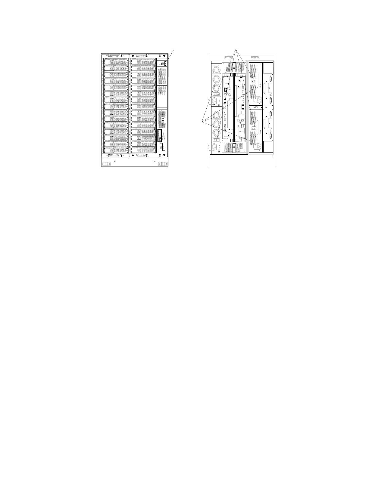
A
RKAJAT RKAJAT
Front Rear
Figure 3.1 Subsystem Power On/Off (Example: Floor [RKXS+ RKAJ+H2J)
3.2.2 Subsystem Power Off
Main switch
Power Unit
RKXS RKXS
C power unit switch
To power off the subsystem:
1. Turn off the main switch.
2. Verify that the POWER LED (green) on the panel is off.
3. Turn off the AC power unit switch of the power unit.
Acer | HDS WMS100™ User and Reference Guide 41
42 Chapter 3 Powering On/Off Procedure
Page 64

Page 65

Chapter 4 Subsystem Architecture and Components
This chapter includes the following:
Configuration Block Diagrams
Redundant Power Supplies
Fibre Channel Interface
Ethernet Interface
Array Frames
Component Names, Locations, and Functions
Acer | HDS WMS100™ User and Reference Guide 43
Page 66

This chapter provides the information on the Fibre and NAS mode l s. The following table
illustrates the sections that provide the explanation for each model. According to the
customer's model, please read the required section.
Fibre Model: Connects disk array subsystem to a host computer with Fibre Channel
interface.
NAS Model: Connects NAS Unit connected to disk array subsystem to a host computer
with LAN interface.
Sections Fibre NAS
4.1.1 WMS100 Rack-Mount Model { { 4.1
4.1.2 WMS100 Floor Model { −
4.2 Redundant Power Supplies { {
4.3 Fibre Channel Interface { −
4.4 Ethernet Interface − {
4.5.1 WMS100 Rack-Mount Model { { 4.5
4.5.2 Floor Model { −
4.6
4.6.1 Front Bezel Component Locations and Functions { {
4.6.2 Component Locations { {
4.6.3 Switch Locations and Functions { {
4.6.4 Connector Locations and Functions { {
4.6.5 LED Locations and Functions { {
{: The explanation is provided.
—: The explanation is not provided.
4.1 Configuration Block Diagrams
This section includes block diagrams for the following:
WMS100 Rack-Mount model.
WMS100 Floor Model.
4.1.1 WMS100 Rack-Mount Model
The configuration block diagrams of the Rack-Mount models are sh own below. The
RKXS/RKAJAT can mount up to 15 disk drives. (The RKXS has a controller that can controller
that can control up to 105 disk drives as RAID.) The disk drives can be assigned to data
disk(s), parity disk(s) (mirror disk(s)) depending on the RAID level. Up to 15 spare disks can
be mounted in any location within the configuration.
44 Chapter 4 Subsystem Architecture and Components
Page 67
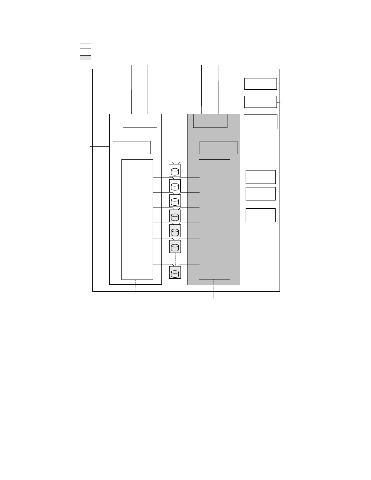
: Basic component and indispensable
optional part
: Option (additional) part
Host computer
LAN
LAN
FC Interface
(Mini-HUB)
Control Unit #0
Cache Unit
FC-SATA
Conversion
FC Interface
(Mini-HUB)
Power Unit
(RKXS) #0
Power Unit
(RKXS) #1
Backup Battery
Unit
AC100/200 V
(Single phase)
AC100/200 V
(Single phase)
Control Unit #1
Cache Unit
Path CTL
0
Path CTL
1
Path CTL
2
Path CTL
3
Path CTL
4
Path CTL
5
FC-SATA
Conversion
Fan Assembly
Fan Assembly
Panel
Assembly
LAN
LAN
Path CTL
14
Disk Drive
(
)
Note
to RKAJAT
Figure 4.1 RKXS System Configuration (When the FC Interface board is not added)
Note: Disk drive: DF-F700-ATE25OR, DF-F700-ATE400R
Acer | HDS WMS100™ User and Reference Guide 45
Page 68

: Basic component and indispensable
optional part
: Option (additional) part
Host computer
LAN
LAN
FC Interface
Control Unit #0
Cache Unit
FC-SATA
Conversion
FC Interface
Power Unit
(RKXS) #0
Power Unit
(RKXS) #1
Backup Battery
AC100/200 V
(Single phase)
AC100/200 V
(Single phase)
Unit
Control Unit #1
Cache Unit
Path CTL
0
Path CTL
1
Path CTL
2
Path CTL
3
Path CTL
4
Path CTL
5
FC-SATA
Conversion
Fan Assembly
Fan Assembly
Panel
Assembly
LAN
LAN
Path CTL
14
Disk Drive
(
)
Note
to RKAJAT
Figure 4.2 RKXS and System Configuration (When the FC Interface board is added)
Note: Disk drive: DF-F700-ATE25OR, DF-F700-ATE400R
46 Chapter 4 Subsystem Architecture and Components
Page 69

: Basic component and indispensable
optional part
: Option (additional) part
RKNAS
NAS
Interface
Memory
(DIMM)
Network
Fan
Assembly
Power
Unit
Memory
(DIMM)
RKNAS
NAS
Interface
Fan
Assembly
Power
Unit
LAN
LAN
NAS
Interface
Control Unit #0
Cache Unit
FC-SATA
Conversion
Path CTL
0
Path CTL
1
Path CTL
2
Path CTL
3
Path CTL
4
Path CTL
5
NAS
Interface
Control Unit #1
Cache Unit
FC-SATA
Conversion
Power Unit
(RKXS) #0
Power Unit
(RKXS) #1
Backup Battery
Unit
Fan Assembly
Fan Assembly
Panel
Assembly
AC100/200 V
(Single phase)
AC100/200 V
(Single phase)
LAN
LAN
Path CTL
14
Disk Drive
(
)
Note
to RKAJAT
Figure 4.3 RKXS and RKNAS System Configuration
Note: Disk drive: DF-F700-ATE250R and DF-F700-ATE400R
Acer | HDS WMS100™ User and Reference Guide 47
Page 70

:
:
Basic component and indispensable optional part
Option (additional) part
From RKXS or RKAJAT
Status
Panel
Disk Drive
(
)
SENC Unit #0 SENC Unit
FC-SATA
Conversion
Note
Path CTL
0
Path CTL
1
Path CTL
2
Path CTL
3
Path CTL
4
Path CTL
5
Path CTL
14
FC-SATA
Conversion
#
1
Power Unit
(RKAJAT) #0
Power Unit
(RKAJAT) #1
AC100/200 V
(Single Phase)
AC100/200 V
(Single Phase)
to RKAJAT
Figure 4.4 RKAJAT System Configuration
Note: Disk drive: DF-F700-ATE250R and DF-F700-ATE400R
48 Chapter 4 Subsystem Architecture and Components
Page 71

4.1.2 WMS100 Floor Model
The configuration block diagrams of the Floor Models are shown below.
The Floor (RKXS+H1J) Model accommodates up to 15 disk drives. The Floor
(RKXS+RKAJAT+H2J) Model accommodates up to 30 disk drives. The disk drives can be
assigned to data disk(s), parity disk(s) and (mirror disk(s)) depending on the RAID level.
Up to 15 spare disks (Floor [RKXS+H1J] Model: up to 1) can be mounted in any locations
within the configuration.
: Basic component and indispensable optional part
: Option (additional) part
Host computer
LAN
LAN
FC Interface
(Mini-HUB)
Control Unit #0
Cache Unit
FC-SATA
Conversion
Path CTL
0
Path CTL
1
Path CTL
2
Path CTL
14
Disk Drive
(Note)
FC Interface
(Mini-HUB)
Control Unit #1
Cache Unit
FC-SATA
Conversion
Power Unit
(RKXS) #0
Power Unit
(RKXS) #1
Backup Battery
Unit
Fan Assembly
Fan Assembly
Panel
Assembly
AC100/200 V
(Single phase)
AC100/200 V
(Single phase)
LAN
LAN
Figure 4.5 Floor (RKXS+H1J) Model WMS100 System Configuration (When FC Interface board is not
added)
Note: Disk Drive: DF-F700-ATE25OR, DF-F700-ATE400R
Acer | HDS WMS100™ User and Reference Guide 49
Page 72

: Basic component and indispensable optional part
: Option (additional) part
Host computer
LAN
LAN
FC Interface
Control Unit #0
Cache Unit
FC-SATA
Conversion
Path CTL
0
Path CTL
1
Path CTL
2
Path CTL
14
Disk Drive
(Note)
FC Interface
Control Unit #1
Cache Unit
FC-SATA
Conversion
Power Unit
(RKXS) #0
Power Unit
(RKXS) #1
Backup Battery
Unit
Fan Assembly
Fan Assembly
Panel
Assembly
AC100/200 V
(Single phase)
AC100/200 V
(Single phase)
LAN
LAN
Figure 4.6 Floor (RKXS+RKAJAT+H2J) Model WMS100 System Configuration (When FC Interface board
is added)
Note: Disk Drive: DF-F700-ATE25OR, DF-F700-ATE400R
50 Chapter 4 Subsystem Architecture and Components
Page 73

: Basic component and indispensable optional part
: Option (additional) part
Host computer
FC Interface
(Mini-HUB)
Fan Assembly
Fan Assembly
Panel
Assembly
FC Interface
(Mini-HUB)
LAN
LAN
Control Unit #0
Cache Unit
FC-SATA
Conversion
SENC Unit #0
FC-SATA
Conversion
Path CTL
0
Path CTL
1
Path CTL
2
Path CTL
14
Disk Drive
(Note)
Path CTL
0
Path CTL
1
Path CTL
2
Control Unit #1
Cache Unit
FC-SATA
Conversion
SENC Unit #1
FC-SATA
Conversion
Power Unit
(RKXS) #0
Power Unit
(RKXS) #1
Backup Battery
Unit
Power Unit
(RKAJAT) #0
Power Unit
(RKAJAT) #1
LAN
LAN
AC100/200 V
(Single phase)
AC100/200 V
(Single phase)
AC100/200 V
(Single phase)
AC100/200 V
(Single phase)
Path CTL
14
Disk Drive
(Note)
Figure 4.7 Floor (RKXS+RKAJAT+H2J) Model WMS100 System Configuration (When FC Interface board
is not added)
Note: Disk Drive: DF-F700-ATE25OR, DF-F700-ATE400R
Acer | HDS WMS100™ User and Reference Guide 51
Page 74

: Basic component and indispensable optional part
: Option (additional) part
Host computer
FC Interface
Fan Assembly
Fan Assembly
Panel
Assembly
FC Interface
LAN
LAN
Control Unit #0
Cache Unit
FC-SATA
Conversion
SENC Unit #0
FC-SATA
Conversion
Path CTL
0
Path CTL
1
Path CTL
2
Path CTL
14
Disk Drive
(Note)
Path CTL
0
Path CTL
1
Path CTL
2
Control Unit #1
Cache Unit
FC-SATA
Conversion
SENC Unit #1
FC-SATA
Conversion
Power Unit
(RKXS) #0
Power Unit
(RKXS) #1
Backup Battery
Unit
Power Unit
(RKAJAT) #0
Power Unit
(RKAJAT) #1
LAN
LAN
AC100/200 V
(Single phase)
AC100/200 V
(Single phase)
AC100/200 V
(Single phase)
AC100/200 V
(Single phase)
Path CTL
14
Disk Drive
(Note)
Figure 4.8 Floor (RKXS+RKAJAT+H2J) Model WMS100 System Configuration (When FC Interface board
is added)
Note: Disk Drive: DF-F700-ATE25OR, DF-F700-ATE400R
52 Chapter 4 Subsystem Architecture and Components
Page 75

4.2 Redundant Power Supplies
Each WMS100 unit is powered by its own set of redundant power supplies, and each power
supply is able to provide power for the entire RKXS unit, should it become necessary.
Because of this redundancy, the WMS100 subsystem can sustain the loss of a power supply
and still continue operation. To make use of this capability, the two power supplies of each
WMS100 unit should be connected either to dual power sources or to different power panels,
so if there is a power failure on one of the sources, the WMS100 subsystem can continue full
operations using power from the alternate source.
RKNAS has no redundancy of power supplies.
Acer | HDS WMS100™ User and Reference Guide 53
Page 76

4.3 Fibre Channel Interface
The WMS100 subsystem supports open system operations. The WMS100 sub system supports
up to 2 fibre-channel ports. Each WMS100 Fibre Channel interface is capable of operating at
data transfer speeds of up to 200 MB/sec. The WMS100 extends up to 4 Fibre Channel ports
by adding optional FC interface board.
The WMS100 supports shortwave multimode optical cables. With these shortwave fibre
channel cables, the WMS100 subsystem can be located up to 300 meters from the opensystem host.
Note: For the interface, refer to Appendix D.
4.3.1 Mini-HUB
When the FC interface board is not added to the control unit, the host interface of WMS100
has Mini-HUB in the control unit, and enhances one port to two host connectors. However,
the link status between the host and the WMS100 is recognized as one port.
PortA-0 PortA-1
Figure 4.9 WMS100 FC Connector
PortA
Mini-HUB
Port
Mini-HUB
Host Connector
54 Chapter 4 Subsystem Architecture and Components
Page 77

4.3.2 Connection Specifications
4.3.2.1 When FC Interface Board is Not Added
The host connector varies, depending on the topology setting of the WMS100 and the
destination of the Fibre Channel cable connection. The following table displays the available
host connector of each topology setting and connection method.
Table 4.1 Available Host Connectors of Each Topology Setting and Connection/Met hod
No. WMS100 Topologies
2 Point-to-Point Auto/1 Gbps/2 Gbps Not Supported Host Connector #0 Not Supported
WMS100 Transfer
Rate
Auto Host Connector 0 Not Supported Host Connector #0 1 Loop
1 Gbps/2 Gbps Host Connector 0
Direct Connection
to the Host
and 1
Switch Connection
Direct Connection
to TagmaStore USP
(see Note)
Direct Connection
to 9900V
Note: TagmaStore USP is an abbreviation for TagmaStore Universal Storage Platform, and it
is a higher-level model in the TagmaStore series.
When connecting the WMS100 directly to the host, the Loop topology is set to the port:
Connect the WMS100 to the host connector 0, when the transfer rate of WMS100 is Auto.
(Do not connect anything to host connector 1.)
Both host connectors 0 and 1 are available, when the transfer rate of WMS100 is 1 Gbps
or 2 Gbps.
The port that the Point-to-Point topology has been set to cannot be connected directly
to the host, TagmaStore USP or 9900V.
When connecting the WMS100 to the Switch, the Point-to-Point topology is set to the port:
Connect the WMS100 to host connector 0. (Do not connect it to host connector 1.)
The port that the Loop topology has been set to cannot be connected to the Switch.
When connecting the WMS100 directly to the TagmaStore USP or 9900V, the Loop topology is
set to the port:
Connect it to host connector 0. (Do not connect anything to host connector 1.)
The port to which the Point-to-Point topology has been set cannot be connected directly
to TagmaStore USP or 9900V.
Acer | HDS WMS100™ User and Reference Guide 55
Page 78

4.3.2.2 When the FC Interface Board is Added
The available Fibre Channel connection configuration varies, depending on the topology
setting of the WMS100 and the destination of the Fibre Channel cable connection. The
following table shows available Fibre Channel connection of each topology setting and
connection method.
Table 4.2 Available Host Connectors of Each Topology Setting and Connection/Met hod
No. WMS100 Topologies
1 Loop Auto/1 Gbps/2
2 Point-to-Point Auto/1 Gbps/2
WMS100 Transfer
Rate
Gbps/ 4Gbps
Gbps/ 4Gbps
Direct Connection to
the Host
Host Connector 0 and 1 Not Supported Host Connector 0
Not Supported Host Connector 0 and 1 Not Supported
Switch Connection
Direct Connection
to the TagmaStore
USP (Note)Direct
Connection to the
9900V
and 1
Note:
TagmaStore USP is an abbreviation for Universal Storage Platform, and it is a higher-level
model in the TagmaStore series.
When connecting the WMS100 directly to the host, the Loop topology is set to the port.
The port that the Point-to-Point topology has been set to cannot be connected directly
to the host, TagmaStore USP or 9900V.
When connecting the WMS100 to the Switch, the Point-to-Point topology is set to the port.
The port that the Loop topology has been set to cannot be connected to the Switch.
56 Chapter 4 Subsystem Architecture and Components
Page 79

4.3.3 Fibre Channel Configuration
4.3.3.1 When the FC Interface Board is Not Added
The following information is not set for each host connector that connects to the WMS100
Fibre Channel.
Port Address
Topology
Transfer Rate
Adding Host Group
Host Group Options
LU Mapping Information
4.3.3.2 When the FC Interface Board is Added
The host connectors that connect the WMS100 Fibre Channel interface cable configure the
respectively independent port. The information described in section
host connector.
4.3.4 Attention to the Host Direct Connection for WMS100
When connecting the WMS100 ports set to the Loop topology directly to both side 0 and side
1 of the host connector (FC interface board addition; side A and side B), consider the
following:
4.3.4.1 When the FC Interface Board is Not Added
Exclusive Access to the Logical Unit: LU mapping cannot be set for each host connector
of WMS100. It is necessary to set the access path between hosts and logical units
according to the assignment of the logical units to the hosts using LUN Manager.
Transfer Rate of the Host: The transfer rate of the WMS100 is set for the port. Both
host connectors 0 and 1 must be connected to the hosts with the same transfer rate.
4.3.4.2 When the FC Interface Board is Added
4.3.3.1 is set for each
One host connector configures one port.
Exclusive Access to the Logical Unit: LU mapping can be set for each port. Set an
accessible logical unit for each port using the LU mapping function.
Transfer Rate of the Host: The transfer rate of the WMS100 is set for each port. Host
connectors side A and side B can be connected to the hosts with different transfer rates.
Acer | HDS WMS100™ User and Reference Guide 57
Page 80

4.4 Ethernet Interface
The WMS100 provides up to 8 LAN ports and supports 1000 BASE-T for Gigabit LAN and 100
Mbps-BASE-TX. The WMS100 supports transfer rates of 1 Gbit/s a n d 100 Mbit/S, and controls
data transmission using the CSMA/CD method.
Note: Refer to Appendix D Interfaces for the supported conditions of the switch in this
subsystem.
4.5 Array Frame
The following array frames are described in this section:
WMS100 rack-mount model
WMS100 floor model
58 Chapter 4 Subsystem Architecture and Components
Page 81

4.5.1 WMS100 Rack-Mount Model
Each RKXS unit contains the physical disk drives, including the disk array groups and the
dynamic spare disk drives. Each rack frame has dual power plugs, which should be attached
to two different power sources or power panels.
The WMS100 can be configured with 1 RKXS and up to 6 RKAJAT units for a total of 10 5 GB
disk drives at a maximum of 38.5 Tbytes RAID5(14D+1P) (using the 393.4 G disk drive).
Table 4.3 Basic Specifications of Rack-Mount Model
Configuration 1 RKXS 1RKAJAT 1 RKNAS Configuratio
n
System appearance
Rack-Mount model Item Model
RKXS RKAJAT RKNAS
Disk drive
used
Host
interface
Note 1: This value of storage capacity is calculated as 1 Gbyte = 1,000,000,000 bytes. (This definition is different from 1 Kbyte =
1,024 bytes.)
Note 2: When FC interface board is not added, one port configures one Mini-HUB, and extends to two host connectors. When
FC interface board is added, control unit implements two ports and two host connectors. One port configures FC interface
independent of another port, and implements one host connector.
Note 3: When the FC interface board is added, the interface type supports 4 Gbps Fibre Channel Optical (Non-OFC).
Note 4: When the FC interface board is added, a maximum data transfer rate is 400
M bytes/s (Fibre Channel) depending on the host I/O condition.
Note 5: For additional information about the global rack-mount model, refer to the Acer | HDS Global 19-Inch Rack Reference
Guide.
Disk drive size (W×D×H)
(mm)
Data capacity (G byte) (Note
1)
Rotational speed (min-1) 7,200 (
Maximum mountable
quantity(unit)
Interface type 2 G bps Fibre Channel
Data transfer speed
(i.e. maximum speed for
transfer to host)
Single
Host
Connectors
Transferred block size (bytes) 512 −
controller
Dual
controller
101.6×146.1×25.4
245.7/393.4 −
15 (
Optical (Non-OFC) (Note 3)
200 M bytes/s
(Fibre Channel) (Note 4)
Fibre Channel: 2 (Note 2) − Number of
Fibre Channel: 4 (Note 2) − 8 (4 for 1RKNAS)
( 1Gbps Ethernet
( 100 Mbytes/s
−
(Ethernet)
Acer | HDS WMS100™ User and Reference Guide 59
Page 82

4.5.2 Floor Model
Each floor model contains physical disk drives, including the disk array groups and the
dynamic spare disk drives. Additionally, each floor model has dual power plugs, which should
be attached to two different power sources or power panels.
Floor (RKXS+H1J) Model can be configured with 15 disk drives at a maximum of 5.5 Tbytes
RAID5 (using the 400 Gbyte disk drive).
Floor (RKXS+RKAJAT+H2J) Model can be configured with 30 disk drives at a maximum of 11.0
Tbytes RAID5 (using the 400Gbyte disk drive).
Table 4.4 Basic Specifications of the Floor Model
Floor Model Item Model
Configuration
Disk drive used
Host interface
Floor (RKXS+H1J) Model
Configuration 1 RKXS+Floor setting kit
(DF-F700-H1J)
System appearance
Disk drive size (W×D×H) (mm) 101.6×146.1×25.4
Data capacity (G byte) (Note 1) 245.7/393.4
Rotational speed (min-1) 7,200
Maximum mountable quantity (unit) 15 30
Interface type 2 G bps Fibre Channel Optical (Non-OFC) (Note 3)
Data transfer speed (i.e. maximum
speed for transfer to host)
Host
Connectors
Single controller Fibre Channel: 2 (Note 2) Number of
Dual controller Fibre Channel: 4 (Note 2)
200 M bytes/s (Fibre Channel) (Note 4)
Floor (RKXS+RKAJAT+H2J)
Model
1 RKXS+1RKAJAT+Floor
setting kit (DF-F700-H2J)
Transferred block size (bytes) 512
Note1: This value of storage capacity is calculated as 1 Gbyte = 1,000,000,000 bytes. (This definition is different from 1
Kbyte = 1,024 bytes.)
Note 2: When FC interface board is not added, one port configures one Mini-HUB, and extends to two host connectors. When
FC interface board is added, control unit implements two ports and two host connectors. One port configures FC interface
independent of another port, and implements one host connector.
Note 3: When the FC interface board is added, the interface type supports 4 Gbps Fibre Channel Optical (Non-OFC).
Note 4: When the FC interface board is added, a maximum data transfer rate is 400
M bytes/s (Fibre Channel) depending on the host I/O condition.
Note 5: For additional information about the global rack-mount model, refer to the Acer | HDS Global 19-Inch Rack Reference
Guide.
60 Chapter 4 Subsystem Architecture and Components
Page 83

4.6 Component Names, Locations, and Functions
This section includes the following:
Front Bezel Component Locations and Functions
RKXS and RKAJAT Component Locations
Switch Locations and Functions
Connector Locations and Functions
LED Locations and Functions
Acer | HDS WMS100™ User and Reference Guide 61
Page 84

4.6.1 Front Bezel Component Locations and Functions
A
W
This section illustrates and describes the locations and functions for the front bezel.
READY LED (green)
ARNING LED (orange)
LARM LED (red)
POWER LED (green)
BUZZER OFF SW
WARNING LED (orange)
Main switch ON Main switch OFF
RKXS
Figure 4.10 Front Bezel Component Locations
Table 4.5 Front Bezel Component Functions
Name Function
ALARM LED (red) Lighting:
Indicates that a failure has occurred which makes the subsystem inoperable.
Blinking:
Low-speed blinking (Note 1): Indicates that a serious failure has occurred while
the power is on.
POWER LED (green)
RKAJAT
WARNING LED (orange) Lighting:
READY LED (green) Lighting:
POWER LED(green) Indicates that the power is supplied to the subsystem.
Main switch on ON: Turns on the power.
Main switch off OFF Turns off the power.
BUZZER OFF SW Press this switch when the buzzer sounds to stop the beep. When a serious
Indicates that a failure occurred, but the subsystem is currently operational.
Blinking:
High-speed blinking (Note 2): Indicates that a failure which does not stop
operation occurred in the unit (it must be deleted with WEB).
Low-speed blinking (Note 1): Indicates that the latest maintenance revision
function of the flash program is executed.
Indicates that the subsystem is operational.
Blinking:
High-speed blinking (Note2): Indicates that the download of the SENC firmware
is executed. (The READY LED may blink for up to 15 minutes. Even if the
READY LED blinks, the subsystem is operational.)
Low-speed blinking (Note1): Indicates that the offline download processing
ended. (It is displayed during the maintenance work.)
hardware failure occurs, (electrical surges of both power supplies and so on), the
buzzer does not stop even when the button is pushed.
62 Chapter 4 Subsystem Architecture and Components
Page 85

Note1: Low-speed blinking:
A
Blinking (One time/1 s)
Note2: High-speed blinking:
Blinking (Eight times/1 s)
WARNING LED (orange)
LARM LED (red)
(1 s)
(1 s)
(1 s)
RKNAS
Off (500 ms) Blinking (Four ti mes/500 m s)
READY LED (green)
POWER LED(green)
Figure 4.11 Front Bezel LED Locations
Table 4.6 Front Bezel LED Functions
Name Function
ALARM LED (red) Indicates that a failure has occurred which makes the RKNAS inoperable.
WARNING LED (orange) Indicates that a failure occurred, but the RKNAS is currently operational.
READY LED (green) Indicates that the RKNAS is operational. (Note)
POWER LED(green) Indicates that the power is supplied to theRKNAS.
Note: When the READY LED on the NAS Unit lights, the NAS unit cannot be accessed from a
host computer. A NAS system accepts access from a host computer only in the "ACTIVE" NAS
OS state. (Refer to section
3.1.3.)
Acer | HDS WMS100™ User and Reference Guide 63
Page 86

4.6.2 Component Locations
The locations of the RKXS and RKAJAT components are shown in the following diagrams:
Disk Drive
Backup Battery Unit
RKXS (front)
Panel Assembly
Figure 4.12 RKXS Component Locations
Disk Drive
RKAJAT (front)
Fan Assembly
Control Unit
Power Unit
RKXS (rear)
SENC Unit
ID Switch (
Note
Power Unit (RKAJAT)
)
RKAJAT (rear)
Figure 4.13 RKAJAT Component Locations
Note: Sets the device ID of the RKAJAT.
64 Chapter 4 Subsystem Architecture and Components
Page 87

4.6.3 Switch Locations and Functions
This section illustrates and describes the locations and functions for switches in the
following hardware components:
Panel Assembly
Power Unit (RKXS)
RKNAS
4.6.3.1 Panel Assembly
BUZZER OFF SW
Mode switch
Main switch
Figure 4.14 Panel Assembly Switch Location
Table 4.7 Panel Assembly Switch Functions
Switch Function
Main switch Turns on/off the power:
: Power on
: Power off
Mode switch Sets the local/remote mode or USP connection by the combination of turning on
and off of the four mode switches.
BUZZER OFF SW Pressing this switch while the buzzer sounds stops the beep. When a serious
hardware failure occurs, (electrical surges of both power supplies and so on), the
buzzer does not stop even when the button is pushed.
Acer | HDS WMS100™ User and Reference Guide 65
Page 88

4.6.3.2 Power Unit (RKXS)
A
A
Figure 4.15 Power Unit Switch Locations
Table 4.8 Power Unit Switch Functions
Switch Function
AC Power Unit Switch Controls the power applied to the subsystem
4.6.3.3 RKNAS
C Power Unit Switch
C Power Unit Switch
Power Unit (RKXS) Power Unit (RKAJAT)
AC Power Unit Switch
Figure 4.16 RKNAS Switch Locations
Table 4.9 RKNAS Switch Functions
Switch Function
AC Power Unit Switch Controls the power applied to the RKNAS
RESET Is used to reset the RKNAS.
66 Chapter 4 Subsystem Architecture and Components
Page 89

4.6.4 Connector Locations and Functions
This section illustrates and describes the locations and functions for connectors in the
following hardware components:
SENC Unit
Power Unit (RKXS)
Control Unit
RKNAS
4.6.4.1 SENC Unit
Control Unit (RKXS)
PATH 0 (to RKAJAT IN)
Figure 4.17 SENC Unit Connector Locations
Table 4.10 Power Unit Connector Functions
Connector Function
PATH 0 Connection connector for RKAJAT Unit ID = 2n (n=0,2,4....C)
4.6.4.2 Power Unit (RKXS)
SENC Unit
PATH 0 (from RKXS or RKAJAT)
PATH 0 (to RKAJAT IN)
Receptor (J1)
Power Unit (RKXS)
Receptor (J1)
Power Unit (RKAJAT)
Figure 4.18 Power Unit Connector Locations
Acer | HDS WMS100™ User and Reference Guide 67
Page 90

Table 4.11 Power Unit Connector Functions
Connector Function
Receptor (J1) Power cable receptacle on the unit side
4.6.4.3 Control Unit
Control Unit
LAN
FC connector (Port 0A-1/Port 1A-1)
FC connector (Port 0A-0/Port 1A-0)
FC Interface Board
NAS Interface Board
FC connector (Port 0B-0/Port 1B-0)
FC connector (Port 0A-0/Port 1A-0)
Figure 4.19 Control Unit Connector Locations
Table 4.12 Control Unit Connector Functions
Connector Function
FC connector Connector for a Fibre channel interface cable.
LAN Connector used to connect a LAN cable.
PCI-E Connector for a PCI-E cable
CTRL Connector for a CTRL cable
PCI-E
CTRL
68 Chapter 4 Subsystem Architecture and Components
Page 91

4.6.4.4 RKNAS
gbe 2 gbe 4
PCI-E
OTHER NAS
FC PORT
mtp 1
gbe 1
gbe 3
CTRL
mng 1
DISK ARRAY
Figure 4.20 RKNAS Connector Locations
Table 4.13 RKNAS Connector Functions
Connector Function
Receptor Power cable receptacle on the RKNAS side
gbe 1 Connector used to connect a cable for gbe 1.
gbe 2 Connector used to connect a cable for gbe 2.
gbe 3 Connector used to connect a cable for gbe 3.
gbe 4 Connector used to connect a cable for gbe 4.
Receptor
CTRL Connector used to connect a CTRL cable.
PCI-E Connector used to connect a PCI-E cable.
mng 1 Connector used to connect a LAN cable for user management.
Other NNC Connector used to connect a LAN cable for connecting with another RKNAS in the
cluster configuration.
Disk Array Connector used to connect with the LAN port for maintenance in the DF Controller.
mtp 1 Connector for the LAN for maintenance
FC Port Connector for the backup subsystem
Acer | HDS WMS100™ User and Reference Guide 69
Page 92

4.6.5 LED Locations and Functions
A
This section illustrates and describes the locations and functions of LEDs in the following
hardware components:
Disk Drive Display
Battery Backup Unit
ENC Unit
SENC Unit
Power Unit
Fan Assembly
Control Unit
RKNAS
4.6.5.1 Disk Drive Display
HDD ACTIVE LED (green)
WARN LED (orange) PWR LED (green)
HDD ALARM LED (red)
LARM LED (red)
Figure 4.21 Disk Drive Display LED Locations
RDY LED (green)
70 Chapter 4 Subsystem Architecture and Components
Page 93

Table 4.14 Disk Drive Display LED Functions
LED Function
HDD ACTIVE LED (green) When on or flashing, it indicates that the disk drive is operational.
HDD ALARM LED (red) When on, it indicates that a failure occurred in the disk drive; the disk drive is inoperable.
ALARM LED (red) Lighting:
When on, it indicates that a failure occurred in the unit; the unit is inoperable.
Blinking:
Low-speed blinking (Note 1): Indicates that a serious failure has occurred while the power is on.
RDY LED (green) Lighting:
When on, it indicates that the unit is operable.
Blinking:
High-speed blinking (Note2): Indicates that the download of the SENC firmware is executed. (The
READY LED may blink for up to 15 minutes. Even if the READY LED blinks, the subsystem is
operational.)
Low-speed blinking (Note1): Indicates that the offline download processing ended. (It is displayed
during the maintenance work.)
WARNING LED (orange) Lighting:
When on, it indicates that a failure occurred in the unit; the unit is inoperable.
Blinking:
High-speed blinking (Note 2): Indicates that a failure which does not stop operation occurred in
unit (It must be deleted with WEB).
Low-speed blinking (Note 1): Indicates that the latest maintenance revision function of the flash
program is executed.
PWR LED (green) When on, it indicates that electricity is supplied to the unit.
Note1: Low-speed blinking:
Blinking (One time/1 s)
(1 s)
Note2: High-speed blinking:
Blinking (Eight times/1 s)
(1 s)
Off (500 ms) Blinking (Four ti mes/500 m s)
(1 s)
Acer | HDS WMS100™ User and Reference Guide 71
Page 94

4.6.5.2 Disk Drive Display (RKAJAT)
A
HDD ACTIVE LED (green)
PWR LED (green)
HDD ALARM LED (red)
WARN LED (orange)
Figure 4.22 Disk Drive Display (RKAJAT) LED Locations
Table 4.15 Disk Drive Display (RKAJAT) LED Functions
LED Function
HDD ACTIVE LED (green) When on or flashing, it indicates that the disk drive is operational.
HDD ALARM LED (red) When on, it indicates that a failure occurred in the disk drive; the disk drive is inoperable.
WARN LED (orange) When on, it indicates that a failure occurs in the unit, so the unit is inoperable.
PWR LED (green) When on, it indicates that electricity is supplied to the unit.
4.6.5.3 Battery Backup Unit
LARM LED(red)
CHARGE LED(yellow)
Figure 4.23 Battery Backup Unit LED Locations
Table 4.16 Battery Backup Unit LED Functions
LED Function
READY LED (green) When on, flashing, or off, it indicates the condition of the battery.
CHARGE LED (yellow) When on or flashing, it indicates the charging status of the battery.
ALARM LED (red) When on, it indicates that a failure occurs in the battery.
When flashing or off, it indicates the condition of the battery.
READY LED(green)
72 Chapter 4 Subsystem Architecture and Components
Page 95

4.6.5.4 SENC Unit
A
SENC Unit
P0 LED / P1 LED (green)
CHK LED (red)
LM LED (red)
Figure 4.24 SENC Unit LED Locations
Table 4.17 SENC Unit LED Functions
LED Function
P0 LED/P1 LED (green) When on, it indicates that the link status of FC-AL (loop 0 or loop 1 side) is normal.
ALM LED (red) When on, it indicates that a failure occurs in the SENC Unit.
CHK LED (red) After turning on the power, it blinks for about 10 seconds (while CUDG is being
executed). However, this blinking does not indicate an abnormal state.
It indicates error factors by the frequency of blinks.
Low-speed blinking (Note 1):
Twice: CUDG error in SENC
Eight times: Selector circuit of the fan is abnormal.
Lighting:
CUDG error in BOOT section of SENC
High-speed blinking (Note 2):
Five times: Fixed data error in flash memory.
Six times: Significant surface error in flash memory
Seven times: SUM check error in flash memory
Note1: Normal blinking:
On
(500 ms)
Blinks and tim es.
Off
(500 ms)
3 s
Note2: High-speed blinking:
On
(400 ms)
Blinks and tim es.
Off
(200 ms)
1 s
Acer | HDS WMS100™ User and Reference Guide 73
Page 96

4.6.5.5 Power Unit
A
A
A
Power Unit (RKXS) Power Unit (RKAJAT)
Figure 4.25 Power Unit LED Locations
Table 4.18 Power Unit LED Functions
LED Function
READY LED (green) When on, it indicates the operating normally.
ALARM LED (red) When on, it indicates the abnormal or in a stop state.
4.6.5.6 Fan Assembly
READY LED (green)
LARM LED (red)
READY LED (green)
LARM LED (red)
LARM LED (red)
Figure 4.26 Fan Assembly LED Locations
Table 4.19 Fan Assembly LED Functions
LED Function
ALARM LED (red) When on or off, it indicates the operating status of the fan assembly.
On: It is abnormal.
Off: It is operating normally or in a stop state.
74 Chapter 4 Subsystem Architecture and Components
Page 97

4.6.5.7 Control Unit
(
)
Control Unit
GP1 LED (Green)
CHK LED (Red)
P0/P1 LED (Green)
CACHE POWER LED (Green)
CHKSTP LED (Red)
FC Interface Board
GP1 LED (Green)
EALM LED (Red)
GP0 LED (Green)
CALM LED (Red)
RST LED (Orange)
GP0 LED
Figure 4.27 Control Unit LED Locations
Table 4.20 Control Unit LED Functions
LED Function
P1 LED (green) When on, it indicates that the link status of FC-AL (loop 1 side) is normal.
P0 LED (green) When on, it indicates that the link status of FC-AL (loop 0 side) is normal.
EALM LED (red) Indicates error factors by the lighting or blinking pattern.
Lighting: When on, it indicates that a failure occurs in the controller (SENC side), so the controller is
inoperable.
Blinking: Normal blinking (Note 1) (CHK LED is on): An exceptional process error detected by the
ENC microprogram.
High-speed blinking (Note 2) (CHK LED is on): An exceptional process error detected by the ENC
microprogram. (stack over)
Normal blinking: (Note 1) (CHK LED is off): Indicates that FLASH write is performed during the
ENC microprogram download. (It is not in the abnormal status.)
CHK LED (red) It indicates error factors by means of number of blinks:
Low-Speed blinking (Note3)
Once: Drive +5 V voltage is abnormal.
Twice: Drive +12 V voltage is abnormal.
Five times: Battery is abnormal.
Six times: Voltage on the controller is abnormal. (Reset of the controller is not canceled)
Seven times: BS 12 V voltage is abnormal.
Nine times: Fan assembly is abnormal.
The following blinking is fast because ENC microprogram detects CUDG error:
High-speed blinking (Note4)
Once: SRAM error.
Twice: SENC hard error.
Three times: Microprogram error in flash memory.
Not blinking: Boot section error of ENC microprogram, RAM error, or ENC hard configuration error.
CACHE POWER
LED (green)
RST LED (orange) When on, it indicates that the controller is resetting.
CALM LED (red) When on, it indicates that a failure occurs in the controller (CTL side), so the controller is
GP0 LED (green) It indicates the status of the interface installed in the controller is normal.
GP1 LED (green) It indicates the status of the interface installed in the controller is normal.
CHKSTP LED (red) When on, it indicates that a failure occurs in the controller (CTL side), so the controller is
When on or off, it indicates the status of the cache memory backup operation.
On: Backup operation is in execution.
Off: Backup operation is not in execution.
inoperable.
inoperable.
Green
Acer | HDS WMS100™ User and Reference Guide 75
Page 98

Note1: Normal blinking:
On
(500 ms)
Off
(500 ms)
Note2: High-speed blinking (EALM LED):
On
(100 ms)
Off
(100 ms)
Note3: Low-speed blinking:
On
(500 ms)
Blinks n times.
Off
(500 ms)
3 s
Note4: High-speed blinking (CHK LED):
On
(400 ms)
Off
(200 ms)
Blinks n times.
1 s
76 Chapter 4 Subsystem Architecture and Components
Page 99

4.6.5.8 RKNAS
A
A
WARNING LED (orange)
LARM LED (red)
READY LED (green)
POWER LED (green)
POWER LED (green)
READY LED (green)
WARNING LED (orange)
Mask A (
)
Note
RKNAS (front)
Mask B (
Note
)
Note: Mask A or Mask B has been affixed.
Figure 4.28 RKNAS (front) Connector Locations
Table 4.21 RKNAS (front) Connector Functions
Name Function
ALARM LED (red) Indicates that a failure has occurred which makes the RKNAS inoperable.
WARNING LED (orange) Indicates that a failure occurred, but the RKNAS is currently operational.
READY LED (green) Indicates that the RKNAS is operational.
LARM LED (red)
POWER LED(green) Indicates that the power is supplied to the RKNAS.
Acer | HDS WMS100™ User and Reference Guide 77
Page 100

A
LINK/ACT
10/100/1000
LINK/ACT
GP1 LED (green)
10/100
READY LED (green)
LARM LED (red)
LINK/ACT
10/100/1000
LINK/ACT
10/100/1000
10/100
GP0 LED (green)
Figure 4.29 RKNAS (rear) LED Locations
Table 4.22 RKNAS (rear) LED Functions
Name Function
LINK/ACT Indicates that the LAN for management is linked or transferring the data.
Green: linked Orange: during the data transfer
10/100/1000 Indicates the transfer rate of the LAN for management Off: 10 M, Green:
100M, Orange: 1000M
10/100 Indicates the transfer rate of the LAN for management Off: 10 M, Green:
100M
READY LED (green) When on, it indicates that the AC/DC power supply operates normally.
When off, it indicates that the AC/DC power supply is abnormal or in a
stop state.
ALARM LED (red) When on, it indicates that a failure occurs in the AC/DC power supply.
GP0 LED (green)/
GP1 LED (green)
It indicates the status of the interface installed in the controller is normal.
78 Chapter 4 Subsystem Architecture and Components
 Loading...