

Acer GW MR19 Schematic

MR19
Service Manual
Service Manual
LCD Monitor MR19
Copyright
Copyright 2009 Innolux Display Corp. Ltd
All Rights Reserved
This manual may not, in whole or in part, be copied, Photocopied, reproduced, translated, or converted to any
electronic or machine readable form without prior written permission of Innolux Display Corp. Ltd.
MR19 Wide Service Manual
- 0 -

1
Table of Contents
Important Safety Notice ......................................................................................02
01 Product Specification .......................................................................................03
02 Flat Panel Specification ....................................................................................29
03 Exploded Diagram ............................................................................................59
04 Troubleshooting..................................................................................................61
05 Spare Parts List .................................................................................................69
06 Schematics and Layouts....................................................................................73
07 Assembly and Disassembly .............................................................................88
1

MR19
Service Manual
Important Safety Notice
1. Safety precautions
This monitor is manufactured and tested on a ground principle that a user’s safety comes first. However,
improper usage or installation may cause damage to the monitor as well as to the user.
Warnings:
z This monitor should be operated only at the correct power sources indicated on the label on the rear of the
monitor. If you’re unsure of the power supply in you residence, consult your local dealer or Power
Company.
z Do not try to repair the monitor by yourself, as it contains no user-serviceable parts. This monitor should
only be repaired by a qualified technician.
z Do not remove the monitor cabinet. There is high-voltage parts inside that may cause electric shock to
human bodies.
z Stop using the monitor if the cabinet is damaged. Have it checked by a service technician.
z Put your monitor only in a lean, cool, dry environment. If it gets wet, unplug the power cable immediately
and consult your closed dealer.
z Always unplug the monitor before cleaning it. Clean the cabinet with a clean, dry cloth. Apply
non-ammonia based cleaner onto the cloth, not directly onto the class screen.
z Do not place heavy object on the monitor or power cord.
2. Product safety notice
Many electrical and mechanical parts in this chassis have special safety visual inspections and the
protection afforded by them cannot necessarily be obtained by using replacement components rated for
higher voltage, wattage, etc. Before replacing any of these components read the parts list in this manual
carefully. The use of substitute replacement parts, which do not have the same safety characteristics as
specified in the parts list, may create shock, fire, or other hazards.
3. Service notes
z When replacing parts or circuit boards, clamp the lead wires around terminals before soldering.
z Keep wires away from high voltage, high temperature components and sharp edges.
z Keep wires in their original position so as to reduce interference.
z Adjustment of this product please refers to the user’s manual.
2
MR19
Service Manual
01 Product Specification
1. General:
MR19 series LCD monitor is designed with a screen 19” SXGA+ TFT LCD panel, LVDS interface, RGB analog and digital
input(option).
It featured with embedded universal AC power supply. This monitor can support maximum resolution up to 1280x1024@60Hz.
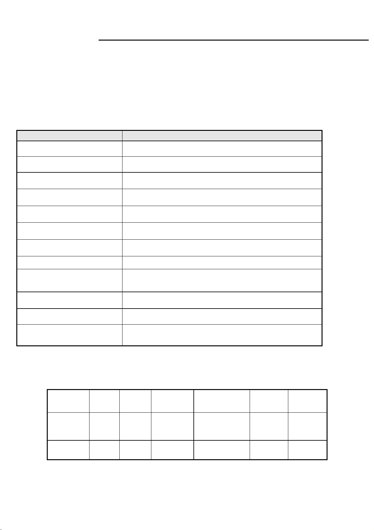
1.1 Main Features
1.1.1 For LGD LM190E08 panel
Features Specifications
Maximum resolution
Back light system 2 CCFL
Actual Resolution display SXGA+ resolution(1280x1024)
Pixel pitch
Display area 19.0 inches diagonal
Contrast ratio 500:1(min.),800:1(typ.)10000:1(DCR)
Response time (Tr+Tf) 5ms(Typ.),10ms(Max)
Viewing angle
Input interface
Power management Compatible with VESA DPMS, Energy Star
Plug & Play VESA DDC/CI
1280x1024@60Hz
0.294mm(H)x0.294mm(W)
85°(L)/ 85°(R),75°(U)/85°(D) typ. (CR>=10)
Analog(D-sub 15pin);
Digital Optional (DVI-D with HDCP function).(option)
OSD language
English,French,Italian,Finnish,Spanish,German,Dutch,Russian
.
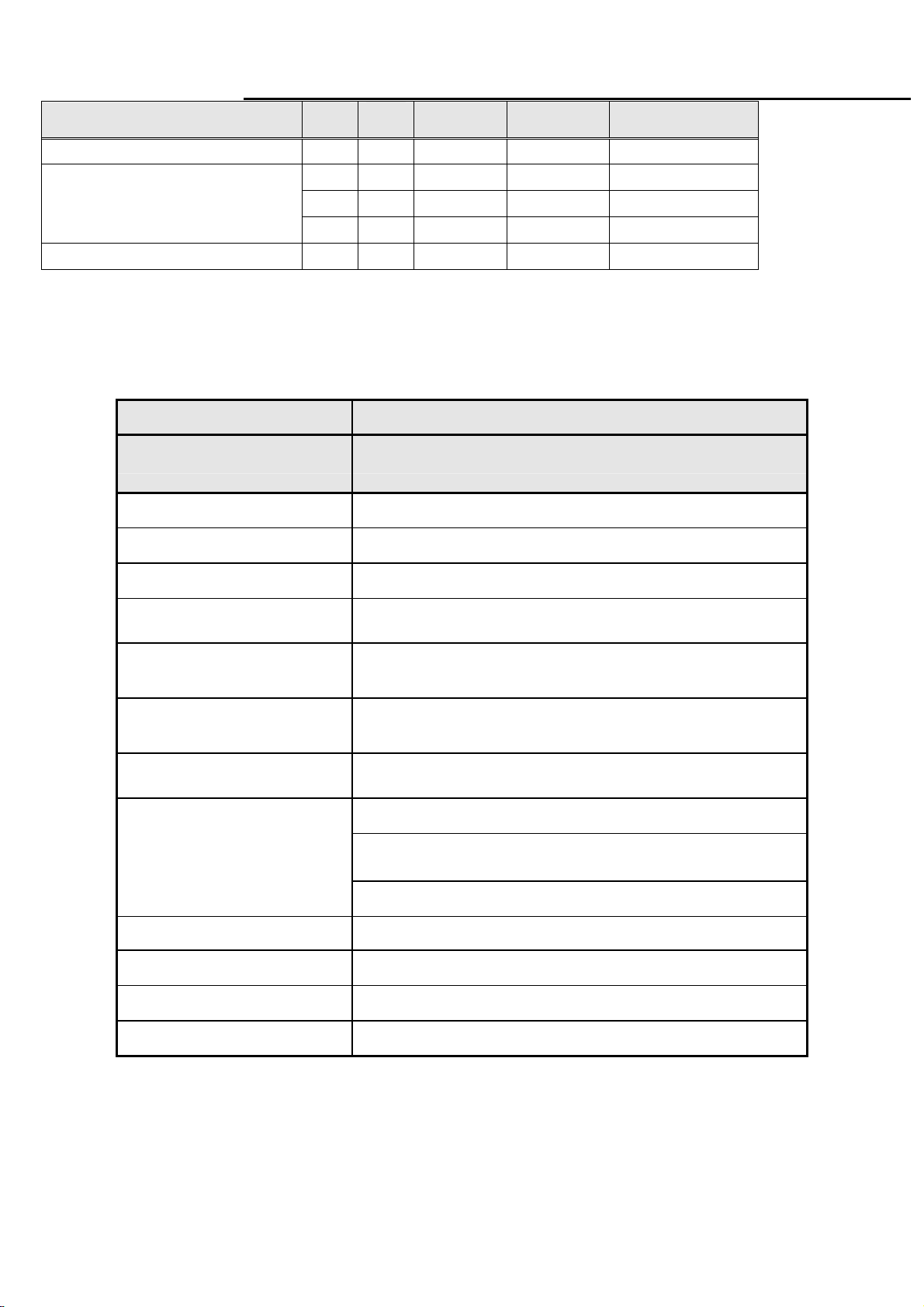
1.2 Accessories
AC
Items
Description 1.8m 1.8m 1.8m 1.8m Multi
Power
Cord
● ● ● ● ● ●
VGA
cable
Audio cable
3
DVI_D
Cable(option)
User’s
manual
Warranty
card

MR19
Service Manual
2. Operation Specifications
The unit should suffer no visible cosmetic damage and should operate with no degradation in display quality during
exposure to the operating conditions and after exposure to the non-operating conditions, in any sequence.
2.1 Environmental conditions
Operating Specification
Temperature range
Relative humidity 20% to 90%
Altitude 0 to 3048 M (10000 ft)
Storage
Temperature range
Relative humidity 10% to 90%
Altitude 0 to 12192M (40000 ft)
0°C to 50°C
-20°C to 60°C
2.2 Safety, EMC, Ergonomics and Compatibility Requirements
Safety & EMC
Ergonomics
Compatibility
Power Management
CB, VCCI, FCC-B, CCC, ,MET
MPRII, ISO-13406-2,
Windows 98/Me/2000, Windows XP, Window Vista
Energy Star
2.3 Electrostatic Discharge Requirements
Item Remark Spec
Contact discharge : ±8KV
Electrostatic Discharge
Air discharge : ±15KV
2.4 Reliability
Items Condition Spec Note
Temp: 25+/-2℃
CCFL Life time
Current: 7mA
Brightness: ≥50%
≧ 50,000 Hours
3. Electrical and Optical Characteristics and Performance
3.1 Main Power Supply
3.1.1
Input characteristics
Items Condition Spec Note
AC Input Voltage range Universal input full range 90~264Vac
AC Input Voltage rating Universal input full range 100~240Vac
AC input frequency range 90~264Vac 47~63Hz
Excluding the
LCD, CCFL
4

MR19
A
Service Manual
AC input frequency rating 100~240Vac 50~60Hz
100Vac 1.0A
AC Input Current
240Vac 0.6A
Inrush Current
Regulator Efficiency
115 V AC cold star,25°C <35A
230 V AC cold star,25°C <70A
DC output full loading ≥75%
Note 1: Before each test, the buck capacitor needs to be discharged.
Before each test, it must be 10 minutes at least after the latest test.
Hot star not component be damaged.
3.1.2 Output characteristics
Items Condition Spec Note
Ripple and Noise
DC Output Voltage
DC output loading capability
Rise Time
Dynamic load change
Hold-up time
Overshoot
Turn on delay time
+14.2 output(PWM mode) <1000mv
+14V output(linear mode) <400mv
+5V output <150mv
audio 5V output <300mv
14v loading:0.2A~1.0A
5v loading:0. 5A~1.0A
audio 5v loading:0A~0.8A
5v loading:0.04A~1.0
14V loading: 0A
audio 5v loading:0A
Vcc5V/1.6A
<50mS
AC input: 100V~240V >10mS
<10%
<2S
VccV:13.5V~16.3V
Vcc5V:4.95V~5.45V
audio 5v:4.5V~5.5V
Vcc14V: 13.5V~20V
Vcc5V: 4.85V~5.45V
audio 5v:4.5V~5.5V
Vcc14V/1.0A
audio 5V/0.8A
See Note1
See note 2
For system
active
For power
saving or DC
off
Power management See Table-1
Note 2: Tested by DC loading side parallel with a 47uF/EC and 0.1uF/Ceramic Capacitors and measured band-width with
DC-20MHz.
DC 24V ripple =2400mV when inverter enters Burst Mode.
3.1.3 Protection characteristics
Protection Condition Spec
OPP nominal AC input 37W ( min )
SCP(short circuit protection) Before fuse with auto-recovery function
OVP(Over voltage protection) Auto recovery <output capacitor voltage
Table-1
5
MR19
Service Manual
Status
Power On(with audio)
Power Saving
Power Off -- -- -- < 1W Off
H-sy
nc
3.2 Backlight Power Supply
Items Specification
V-s y
nc
on on active ≤34W Blue
off on blanked < 1W Amber
on off blanked < 1W Amber
off off blanked < 1W Amber
Video Power LED
Panel
Lamp 2 CCFL
Input Voltage DC 13.5~16.3 V
Input current 0.8A (Typ.), 1.0A (Max.)
On/Off switch level
Brightness PWM Duty (ACM Off)
Brightness PWM Duty (ACM On)
CCFL operating Voltage 800Vrms (Typ.),
CCFL Current
LGD LM190E08 panel
5.5V≧Von≧ 2.0 V (on)
-0.3v ≤ Voff ≤ 0.8 V (off)
30%~100%
10%~100%
2.0mA (min.)
7.5mA (Typ.)
8.0 mA (Max.)
CCFL startup voltage
Operating frequency 40~60KHz
Protect delay time > 1 second
Efficiency ≥70% (Using dummy load)
≧1700 Vrms (0˚C)
6

MR19
Service Manual
3.3 Input / Output Signal Specifications
3.3.1 Video signals
Signal Cable
Analog
Digital(option)
Sync
Items Condition Spec OK
15 pin D-Sub
DVI-D(option)
Signal type Separate analog R,G,B
Level 700 mV +/- 5% (peak to
Impedance 75 Ohms +/- 2% Ohms
Base on TMDS technology
Signal type Separate H/V-sync
Level Logic High: 2.0V ~ 5.5V
Termi nal
Color: BLACK
Length: 1800
+/-
20 mm
Color: BLACK
Length: 1800
+/-
20 mm
peak)
(Positive/Negative)
Logic Low: 0V ~ 0.8V
(TTL level)
≧
2.2k
Ω
●
●
●
●
●
●
●
●
Note
Monitor side should be
blue right angle.
NO DVI cable in carton
For 15 pin D-sub
For 15 pin D-sub
Refer to VESA VSIS
Standard V1R1
Ω
for application
2.2K
3.3.2
Signal Timing
Through D-SUB and DVI(option) connectors, this unit can support FH= 31~83 KHz, Fv=56~76 Hz.
Modes details as below:
VESA MODES
Horizontal Vertical
Mode Resolution
640*480@60Hz 31.469 N 59.941 N 25.175
640*480@72Hz 37.861 N 72.809 N 31.5
VGA
SVGA
640*480@75Hz 37.5 N 75 N 31.5
800*600@56Hz 35.156 P 56.25 P 36
800*600@60Hz 37.879 P 60.317 P 40
800*600@72Hz 48.077 P 72.188 P 50
800*600@75Hz 46.875 P 75 P 49.5
1024*768@60Hz 48.363 N 60.004 N 65
1024*768@70Hz 56.476 N 70.069 N 75
Nominal
Frequency
+/-0.5KHz
Sync
Polarity
Nominal
Frequency
+/-1Hz
Sync
Polarity
Nominal Pixel
Clock (MHz)
XGA
SXGA
1024*768@75Hz 60.023 P 75.029 P 78.75
1152*864@75Hz 67.5 P 75 P 108
1280*960@60Hz 60 P 60 P 108
1280*1024@60Hz 63.981 P 60.02 P 108
7

MR19
Service Manual
1280*1024@75Hz 79.976 P 75.025 P 135.000
WXGA
WSXGA+
VGA
SVGA
XGA
WXGA
Note: 1. Non-interlace signals only (An interlace signal cannot be display)
2. Please refer to F/W specification for more detail
3. Each frequency of Power Macintosh and Sun Ultra is a reference value
IBM MODES
720x400@70Hz 31.469 N 70.087 P 28.322
MAC MODES
640*480@66.7Hz 35 P
832*624@74.55Hz 49.722 N 74.55 N 57.283
1152*870@75Hz 68.681 N 75.062 N 100
Other MODES
66.667 N 30.24
3.3.3
Timing requirements
Item Condition Specification
Horizontal
Vertical
Out of range
3.3.4
DDC data
Sync polarity: (+) or (-)
Sync polarity: (+) or (-)
Excluding Horizontal
(31~83)KHz or
Vertical 56~76 Hz
31~83KHz
56~76 Hz
Message “
EDID Standard Compliance
EDID File Format : VESA’s EDID Standard Version #3, Revision #0,
EDID Structure : Version #1, Revision #3.
EDID Data Table : See the file of LE19U1-DR4-16
4. LCD Characteristic & Performance
4.1 Panel general specifications
Frequency out of range” on screen
General Specifications
(1) The test methods for the below items’ definition, please refer to the specification of LM190E08-TLJ2 panel
Supplier LG
Model name LM190E08-TLJ2
Display Area 19.0 inches diagonal
8
MR19
Service Manual
Pixel Pitch 0.294mm(H)x0.294mm(W)
Display Colors: 16.7Million (6bit+Hi-FRC)
Number of Pixel 1280x1024 pixels
Pixel Arrangement RGB vertical stripe
Brightness 250cd/m2 (Typ.)
Contrast Ratio 800:1 (Typ.)
Viewing Angle Hor:170°, Ver: 160°(Typ)
Brightness Uniformity
Display Mode Normally White
Response Time(Tr+Tf) 5ms (Typ.), 10ms (Max.)
Surface Treatment Haze 25%, Hard-coating (3H)
Lamp 2 CCFL
Notes: Other panel source, please refer to the panel specifications.
≧75%
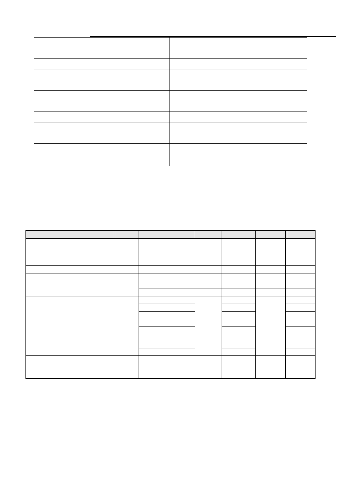
4.2 Optical characteristic of LCD panel
(1) The test methods for the below items’ definition, please refer to the specification of LM190E08-TLJ2 panel.
Item Unit Conditions Min. Typ. Max. Remark
Viewing Angle
Contrast ratio
Response Time
Color / Chromaticity
Coordinates (CIE)
Color Coordinates (CIE) White
Luminance Uniformity
White Luminance at
CCFL 6.5mA(center point)
[degree]
[degree]
[degree]
[degree]
Normal Direction 500 800
[msec] Rising Time - 1.3 2.6
[msec] Falling Time - 3.7 7.4
[msec] Rising + Falling - 5 10
Red x 0.640
Red y 0.335
Green x 0.298
Green y 0.608
Blue x 0.147
Blue y 0.070
[%] 9 points measurement 75%
[cd/m2]
Horizontal (Right)
CR >= 10 (Left)
Vertical (Up)
CR >= 10 (Down)
White x 0.313
White y
200 250 -
70
70
60
70
Typ-0.03
85
85
75
85
0.329
Typ+0.03
-
-
-
-
4.3 Brightness output
The test to verify specifications in this section shall be performed under the following standard conditions unless otherwise
noted.
Temperature : 25 ± 5°C
Test pattern : white
Video Resolution : 1280x1024
Video input level : 700 mV ± 2%
Warm-up time : 30 minutes
9

MR19
Service Manual
Item Condition SPEC
Brightness
Grey Scale
4.4 White balance
The test standard conditions refer to Sec 3.3. (Brightness control is at 100 contrast control is at 50.)
Brightness=100%
Contrast = 100%
Brightness=100%
Contrast = 100%
≧ 200 cd/m
the last 3~8 levels of 32
grey scales is combined
2
Cool
Warm
User
4.5 Brightness uniformity
The test standard conditions refer to Sec 3.4.
Mode
9300K 0.283 ± 0.030 0.297 ± 0.030
6500K 0.313 ± 0.030 0.329 ± 0.030
Panel While x Panel While y
)(backlight points nine of luminance Min.
≥
)(backlight points nine of luminance Max.
L/2
4 6
Chromaticity Coordinate
x y
(4)
%75
L/10
5
W/10
1 2
7
8
3
9
W/2
Fig.3
10

MR19
Service Manual
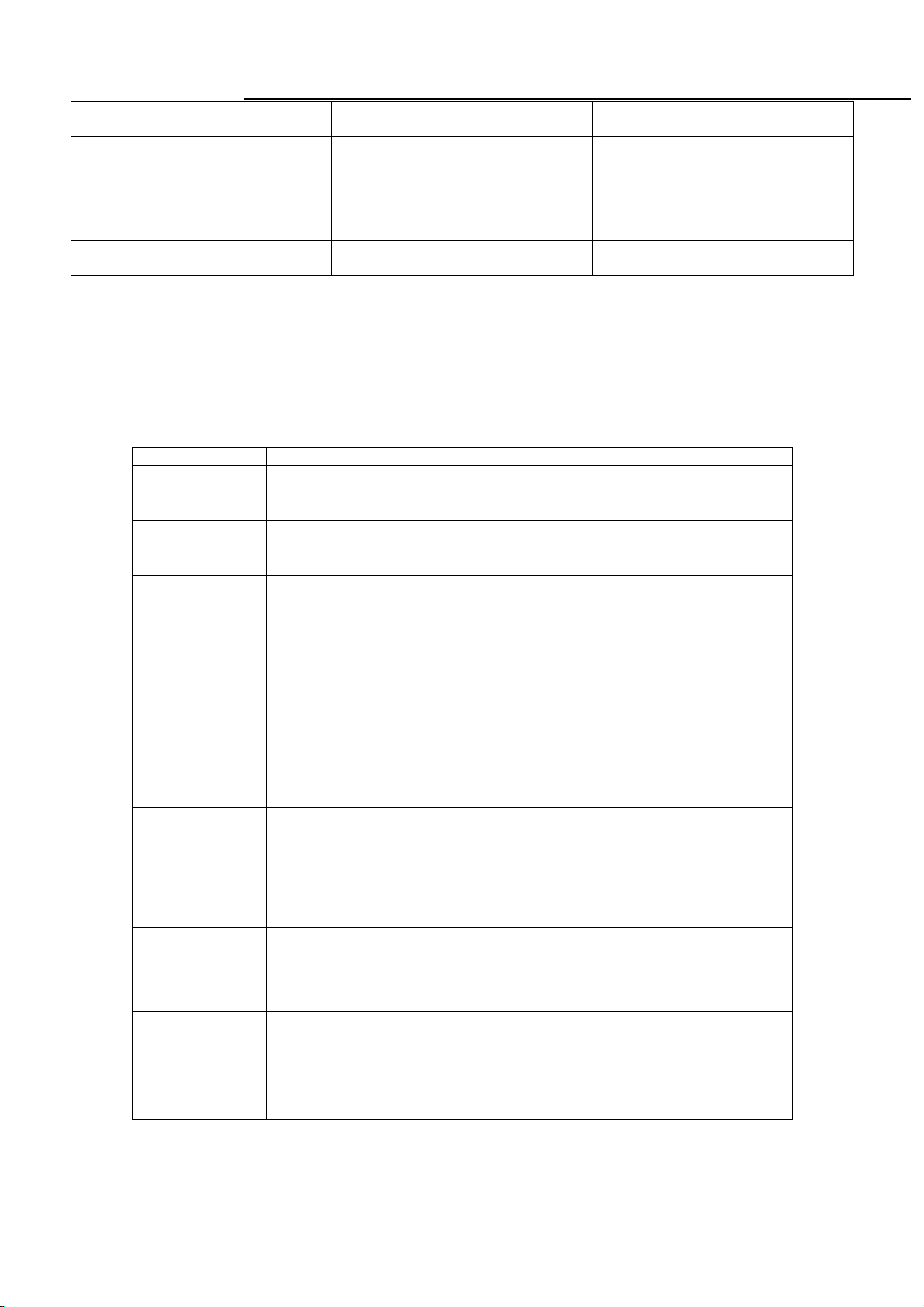
4.6 Audio Signal
Items Specification
Input impedance
Frequency response range
Signal to noise ratio
Output power
Loading impedance
Note: The low pass RC Filter (R=100Ω / C=0.047uF) for Class-D output power and THD+N measurement, and under 1KHz, 1Vrms
and sine wave input.
≧ 10K ohm
200Hz –20kHz
≧ 40 dB
≦1 W + 1 W(±20% tolerance), THD 10%.
4 ohm
5. Function Specifications
All the tests to verify specifications in this section shall be performed under the following standard conditions unless
otherwise noted. The standard conditions are:
Temperature : 25 ± 5°C
Warm-up time : 30 minutes minimum
Checking display modes : All the specified modes
5.1 Keypad Function
5.1.1
注:1.if current Menu is Language menu, when you press
[AUTO] key, it will not save your select and
Control buttons
A. When OSD un-displays , press [AUTO] to perform auto-adjustment
[AUTO]
[MENU]
[>], [<]
[POWER] Power on or power off the monitor
B. When OSD displays, and the current Menu is Main Menu press [AUTO] to turn off the
Main Menu, or press [AUTO] to return to previous level menu.
A. When OSD isn’t shown on screen, press [MENU] to enter OSD interface.
B. When OSD displays, press [MENU] to perform function of menu icon that is highlight or
enter next level menu, and if the Menu is the last layer of OSD press [MENU] to finish
adjust and turn off Menu.
A. When “MENU OSD” displays, press these keys to change the contents of an
adjustment item, or change an adjustment value.
B. When “MENU OSD” un-displays, press [<] to show “Audio” OSD, press [>] to show
“Theme Mode” OSD.
return to
[MENU]
previous menu.
key, it will save your select and return to
previous menu. and when you press
11

MR19
Service Manual
5.1.2
FUNCTION
FACTORY
MODE
Hot Key Operation
AUTO MENU
●
HOT KEY OPERATION
<
>
POWER
ON
DESCRIPTION
Press [AUTO] at the same time, and then press
[POWER] for DC power on. OSD menu will be
shown with “F” on the left top. Select “F” for
entering factory mode
Volume
Theme Mode
●
●
Adjust Volume
Select Theme Mode
12

MR19
Service Manual
5.2 OSD Structure
The On-Screen Display (OSD) shall be an easy to use icon based menu through keypad OSD buttons or remote control
unit. The unit shall leave the factory with all OSD controls set to their default values.
Analog:
“Picture” will be the first selected function while user power on main menu.
First Second Third Fourth Control Value Default
Auto
VGA
Input
Audio Volume 50
Picture
Geometry
Advanced
DVI
Brightness 80
Contrast 50
Gamma
H-Position 50
V-Position 50
Clock 50
Phase
Color
Language
Resolution
Reminder
Information
Enable Reset
Disable
Gamma2.0
Gamma2.2
Gamma2.4
Warm Default color
Cool
Customer
Color
Theme Mode
English
Français
Italiano
Español
Hollands
Русский
Suomalainen
Deutsch
Gamma 2.2
Red 50
Green 50
Blue 50
Movie
Game
Picture
User
Tint/Hue 50
Saturation 50
Sharpness 50
Dynamic
Enable
Disable
English
Disable
Disable
13

MR19
Service Manual
DVI(option):
If our monitor is in Dual mode, the gray area below will be the function which could not be adjusted.
First Second Third Fourth Control Value Default
Auto
VGA
Input
Audio Volume 50
Picture
Geometry
Advanced
DVI
Brightness 80
Contrast 50
Gamma
H-Position
V-Position
Clock
Phase
Color
Language
Resolution
Reminder
Information
Enable Reset
Disable
Gamma2.0
Gamma2.2
Gamma2.4
Warm Default color
Cool
Customer
Color
Theme Mode
English
Français
Italiano
Español
Hollands
Русский
Suomalainen
Deutsch
Disable
Gamma 2.2
Red 50
Green 50
Blue 50
Movie
Game
Picture
User
Tint/Hue 50
Saturation 50
Sharpness 50
Dynamic
Enable
Disable
English
Disable
14
MR19
Service Manual
Theme Mode Brightness Contrast
Movie 100 54
Game 100 58
Picture 100 50
User(After Reset all) 80 50
Remark:
1. Main OSD will Show 10 Second on the Screen,if there is No Operation on the OSD,And ±1 Second is accepted.
2.Gamma 2.0(2.0±0.2), Gamma 2.2(2.2±0.2), Gamma 2.4(2.4±0.2).
3. When dynamic be enabled, after adjusting theme mode/Color Menu, DCR function will be turn off automatically.
5.3 Gateway OSD Message
Item Description
When User Press Hot-Key “Auto” or use main Menu “Auto processing”
Auto Processing
No Signal
Frequency out of
range
Resolution
Reminder
function, will show this message ,and the monitor do the auto process
function.
When the video cable is connect, but there is no active signal input, will
show this message, then enter into power saving mode.(will Show 3
seconds)
1. When meet the case as below:
a. Input signal is detected by the system;
b. Input signal is out of the system support rang or supported table which
may have following case:
-input signal is out of the support H or V frequency range;
-input signal is in specified blocked list;
-Input signal is out of the system support specification;
Then will show this message.
2. The menu will be shown as:
a. Move around the full screen;
b. Desktop background in Black;
c. Continue 5 minutes and then step into Power Saving Mode.
When user entering into “Advanced” menu, user could select “Resolution
reminder” item. After selecting “Resolution reminder”, main menu will show
“Your Computer screen resolution may not match this monitor’s optimum
1600x900 setting. To adjust your screen resolution and see your
computer’s printed or online documentation. Press the AUTO button on the
side of this monitor after adjusting the screen resolution. ”
Information
Reset
Input Menu
While user entering into “Advanced” menu, user could select “Information”.
Main menu will show “Mode:, Input: , OSD Vers: ,SN ”.
Go to “Main menu” and select “Reset” function. After select “Reset”,
monitor will show a “Reset All” pop up window.
This Menu will Show at the Cases Below(3 Seconds) :
1. AC/DC On;
2. Power Saving On;
3. Burn In On;
4. Switch Source;
5. Plug and pull out Cable.
15
MR19
Service Manual
6. SOP of PCBA ISP Programming
6.1 Operational condition:
Equipment: PC, ISP card, signal cable and power cable.
ESD requirements: antistatic wrists, antistatic gloves(fingers), and connecting cable
Name of ISP program: ISP_Tool_V4.4.2.4
Manufacture of FW IC:PMC/SST/MX
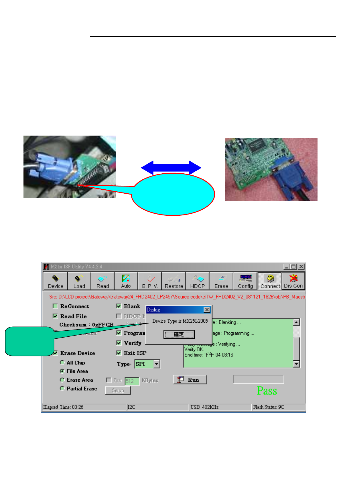
6.2 Operational steps:
1. Connection: connect PC to PCBA with signal cable, and then keep AC and DC in open state.
Signal cable
One port of ISP
program card is
connected to
PC
2. Adjust ISP programming
Firstly, double click ISP_Tool_ V4.4.2.4 exit and click “Connect ” button; The ISP tool will connect to
monitor automatically, and it will show flash IC type automatically
FW IC
Model
16

MR19
Service Manual
Secondly﹐download FW software: first select “READ”, and then load FW software in Rooter
(Fig.2).
Software
Checksum value
FW BIN file
Thirdly, select “AUTO”, and keep its default value. Click “RUN” for beginning programming. There will
be prompting if programming is OK.
17

MR19
Service Manual
◆Note: if programming fails or success rate is not high, click “Config” and adjust its speed to lower
in “I2C Speed Setting”and check Communication Setting. If connect port is print port, please check
port type.
18

MR19
Service Manual
3. Flow Chart
19

MR19
Service Manual
7. SOP of EDID
7.1 Request of hardware and software:
1. Software
a.port95nt.exe
b.Edid.exe
c.MR19 model
2. Hardware
a. PC(winXP or win2000)1PCS;
b. Tool(EDID Card、VGA cable & DVI cable)
7.2 Operational steps:
1. First set up Port95nt.exe
20

MR19
Service Manual
2. Click next button continually then can finish setting.
21

MR19
Service Manual
EDID Tool Set up
A : USB interface provide +5V DC power(No Power is ok )
B : Connect DDC Card and PC with collateral interface ;
C :VGA、DVI use different cable to link DDC and PC
A
A
B
B
C
C
22

MR19
B C
Service Manual
EDID ISP Card:
A
A:Collateral printing interface (connect with PC)
B : VGA interface (one VGA connect with PC to provide signal for monitor the other one connect with
PC VGA interface to write VGA EDID, Write EDID can without providing signal)
C : DVI interface (connect with Monitor)
23

MR19
Service Manual
3. Write EDID Process:
3.1 Choose File menu in main menu ,choose Auto Write button,click S/N blank .
MR19
24

MR19
Service Manual
3.2 Cloose the Model in main menu, and the password is 1234.
MR19
25
 Loading...