

Page 1

Acer Altos G310
User’s guide
Page 2

Copyright © 2004 Acer Incorporated
All Rights Reserved.
Acer Altos G310 series
User’s guide
1st Issue: February 2004
Changes may be made periodically to the information in this publication without obligation
to notify any person of such revision or changes. Such changes will be incorporated in new
editions of this manual or supplementary documents and publications. This company makes
no representations or warranties, either expressed or implied, with respect to the contents
hereof and specifically disclaims the implied warranties of merchantability or fitness for a
particular purpose.
Record the model number, serial number, purchase date, and place of purchase information in
the space provided below. The serial number and model number are recorded on the label
affixed to your computer. All correspondense concerning your unit should include the serial
number, model number, and purchase information.
No part of this publication may be reproduced, stored in a retrieval system, or transmitted, in
any form or by any means, electronic, mechanical, photocopy, recording, or otherwise,
without the prior written permission of Acer Incorporated.
Model Number : _________________________________
Serial Number: ___________________________________
Purchase Date: ___________________________________
Place of Purchase: ________________________________
Acer and the Acer logo are registered trademarks of Acer Inc. Other company’s product
names or trademarks are used herein for identification purposes only and belong to their
respective companies.
Page 3

iii
Notices
FCC notice
Class A devices do not have an FCC logo or FCC IDE on the label. Class B devices
have an FCC logo or FCC IDE on the label. Once the class of the device is
determined, refer to the following corresponding statement.
Class B equipment
This device has been tested and found to comply with the limits for a Class B
digital device pursuant to Part 15 of the FCC Rules. These limits are designed to
provide reasonable protection against harmful interference in a residential
installation. This device generates, uses, and can radiate radio frequency
energy, and if not installed and used in accordance with the instructions, may
cause harmful interference to radio communications.
However, there is no guarantee that interference will not occur in a particular
installation. If this device does cause harmful interference to radio or television
reception, which can be determined by turning the device off and on, the user
is encouraged to try to correct the interference by one or more of the following
measures:
• Reorient or relocate the receiving antenna
• Increase the separation between the device and receiver
• Connect the device into an outlet on a circuit different from that to which
the receiver is connected
• Consult the dealer or an experienced radio/television technician for help
Page 4

iv
Notice: Shielded cables
All connections to other computing devices must be made using shielded cables
to maintain compliance with FCC regulations.
Notice: Peripheral devices
Only peripherals (input/output devices, terminals, printers, etc.) certified to
comply with the Class A or Class B limits may be attached to this equipment.
Operation with noncertified peripherals is likely to result in interference to
radio and TV reception.
Caution: Caution! Changes or modifications not expressly
approved by the manufacturer could void the user’s authority,
which is granted by the Federal Communications Commission, to
operate this server.
Use conditions
This part complies with Part 15 of the FCC Rules. Operation is subject to the
following two conditions: (1) this device may not cause harmful interference,
and (2) this device must accept any interference received, including interference
that may cause undesired operation.
Notice: Canadian users
This Class A/Class B digital apparatus meets all requirements of the Canadian
Interference-Causing Equipment Regulations.
Laser compliance statement
The CD-ROM drive in this server is a laser product. The CD-ROM drive’s
classification label (shown below) is located on the drive.
CLASS 1 LASER PRODUCT
CAUTION: INVISIBLE LASER RADIATION WHEN OPEN. AVOID EXPOSURE TO
BEAM.
Page 5

v
Important safety instructions
Read these instructions carefully. Save these instructions for future reference.
1 Follow all warnings and instructions marked on the product.
2 Unplug this product from the wall outlet before cleaning. Do not
use liquid cleaners or aerosol cleaners. Use a damp cloth for
cleaning.
3 Do not use this product near water.
4 Do not place this product on an unstable cart, stand, or table. The
product may fall, causing serious damage to the product.
5 Slots and openings on the back or bottom side of the chassis are
provided for ventilation; to ensure reliable operation of the
product and to protect it from overheating, these openings must
not be blocked or covered. The openings should never be blocked
by placing the product on a bed, sofa, rug, or other similar surface.
This product should never be placed near or over a radiator or
heat register, or in a built-in installation unless proper ventilation
is provided.
6 This product should be operated from the type of power indicated
on the marking label. If you are not sure of the type of power
available, consult your dealer or local power company.
7 Do not allow anything to rest on the power cord. Do not locate
this product where persons will walk on the cord.
8 If an extension cord is used with this product, make sure that the
total ampere rating of the equipment plugged into the extension
cord does not exceed the extension cord ampere rating. Also,
make sure that the total rating of all products plugged into the
wall outlet does not exceed the fuse rating.
9 Never push objects of any kind into this product through chassis
slots as they may touch dangerous voltage points or short out
parts that could result in a fire or electric shock. Never spill liquid
of any kind on the product.
10 Do not attempt to service this product yourself, as opening or
removing covers may expose you to dangerous voltage points or
other risks. Refer all servicing to qualified service personnel.
11 Unplug this product from the wall outlet and refer servicing to
qualified service personnel under the following conditions:
a When the power cord or plug is damaged or frayed
Page 6

vi
b If liquid has been spilled into the product
c If the product has been exposed to rain or water
d If the product does not operate normally when the operating
instructions are followed. Adjust only those controls that are
covered by the operating instructions since improper
adjustment of other controls may result in damage and will
often require extensive work by a qualified technician to
restore the product to normal condition.
e If the product has been dropped or the cabinet has been
damaged
f If the product exhibits a distinct change in performance,
indicating a need for service.
12 Replace the battery with the same type as the product's battery we
recommend. Use of another battery may present a risk of fire or
explosion. Refer battery replacement to a qualified service
technician.
13 Warning! Batteries may explode if not handled properly. Do not
disassemble or dispose of them in fire. Keep them away from
children and dispose of used batteries promptly.
14 Use only the proper type of power supply cord set (provided in
your accessories box) for this unit. It should be a detachable type:
UL listed/CSA certified, type SPT-2, rated 7A 125V minimum, VDE
approved or its equivalent. Maximum length is 15 feet (4.6
meters).
Page 7

Notices iii
FCC notice iii
Class B equipment iii
Laser compliance statement iv
Important safety instructions v
1 System information 1
Product briefing 3
Processor 3
Memory subsystem 3
Storage 4
Graphics interface 4
Networking 4
I/O ports 4
Serial ATA ports 5
Caring features 6
Product specification summary 7
2 System tour 9
System board 11
Mainboard layout 11
Jumper settings (JP8) clear CMOS 14
External and internal structure 15
Front bezel 15
Front panel 17
Rear panel 19
Internal components 21
vii
Contents
3 Getting Started 23
Setting up the system 25
Preinstallation requirements 25
Selecting a site 25
Checking the package contents 25
System startup 26
Turning on the system 26
Turning off the system 27
Power-on problems 27
BIOS POST Checkpoint Codes 28
Bootblock Initialization Codes 28
Bootblock Recovery Codes 29
POST code checkpoints 31
Beep Codes 35
Page 8

viii
4 Configuring the system 37
Upgrading the system 39
Installation precautions 40
ESD precautions 40
Preinstallation instructions 41
Post-installation instructions 41
Opening the server 42
Before opening the server 42
To remove the side panel 43
To remove the front panel 44
Installing and removing storage devices 45
To install a 5.25-inch storage device 45
Upgrading the CPU 47
To remove a CPU with heatsink 47
To install a CPU with heatsink 49
Upgrading the system memory 51
Memory configuration 51
To remove a DIMM 52
To install a DIMM 53
Reconfiguring the system memory 53
Installing an expansion card 54
To install an expansion card 54
Installing and removing a hard disk 57
To remove a hard disk 57
To install a hard disk 58
Configuring the SCSI/SCSI RAID HBA 59
How to use SCSI HBA setup utility 59
Loading HBA Default Settings 59
How to use SCSI RAID HBA setup utility 59
How To Create RAID 1 (Mirror) volume with a
Hot Spare Disk 59
RAID Volume Initialization 60
Exit and Restart the server 60
MegaRAID Configuration Utility 61
Load RAID Card Default Setting 61
Create RAID1 Volume 61
Assign Hot Spare Disk 62
Initialize RAID Volume 62
Save And Exit MegaRAID Configuration Utility 62
Configuring Parallel ATA and Serial ATA devices 63
ATA Operate Mode 63
Intel ICH5R Serial ATA RAID introduction 64
Parallel ATA and Serial ATA device configurations
supported by Intel ICH5R 64
Contents
Page 9

ATA Operate Mode BIOS configuration 64
Using the Intel RAID Option ROM 64
Creating, Deleting and Resetting RAID Volumes 64
Installation of Intel Application Accelerator RAID Utility71
RAID migration instructions 75
Create RAID Volume from Existing Disk 76
5 BIOS setup 81
BIOS setup 83
Entering BIOS setup 84
Main 86
Advanced 88
Peripheral Configuration 89
IDE Configuration 91
Primary IDE Master 93
Floppy Configuration 95
PCI/PnP Configuration 96
Boot Settings Configuration 98
OnBoard Device Configuration 101
Event Log Configuration 102
Remote Access Configuration 104
System Health Monitoring 105
Power 106
Boot 108
Boot Device Priority 109
Security 110
Exit 112
ix
Appendix A: Management software installation115
Installing ASM 117
System requirements 117
ASM Agent 117
ASM Console 117
System setup 117
Installing ASM Agent (Windows version) 118
Installing ASM Console (Windows version) 118
Installing ASM Agent (Linux version) 119
Index 121
Page 10

x
Contents
Page 11

1 System
information
Page 12

The Acer Altos G310 series server is an entry
level single-processor general purpose
system. The system offers a new standard for
flexible productivity ideal for small business
or workgroup applications.
Page 13

Product briefing
This section provide basic information concerning the configuration of
your Altos G310 system.
Processor
• Single 2.8 GHz Intel® Pentium® 4 processor with 533 MHZ FSB
- or -
• Single 3.0 to 3.4 GHz Intel
FSB
• CPU Hyper-Threading Technology support
Memory subsystem
• Four (184 - pin) DIMM slots
• DDR 333/400 MHz Unbuffered memory modules supported
• Maximum upgrade - 4 GB
Warning! Functionality issues may be encountered if mixed
memory types are installed on the same server board. DIMM
modules of identical type, banking and stacking technology, and
vendor should be installed in the Altos G310.
®
Pentium® 4 processor with 800 MHz
3
Caution! When using multiple memory modules it is
recommended that you AVOID using modules from different
manufacturers or that run at different speeds from each other.
Note: To run 400 MHz memory at full speed requires a processor
with 800 MHz system bus frequency.
Note: To run 333 MHz memory at full speed requires a processor
with 533 MHz system bus frequency.
Page 14

4
Note: 333 MHz memory will run at 320 MHz when used with a
processor with 800 MHz system bus frequency.
1 System information
Storage
• 5.25 inch IDE CD-ROM drive
• 3.5 inch Floppy disk drive
• Support for three (max) hard disk drives
• Four additional 5.25 Inch device bays for add-on options such as:
• DDS4 DAT 20/40 GB tape backup drive
• DAT72 36/72 GB tape backup drive
• AIT1 35/91 GB tape backup drive
• DVD-ROM, DVD-RW, DVD-Dual or other optical drive
Graphics interface
• On-board AGP 8X slot
Networking
• Single Gigabit Ethernet port
I/O ports
• Front
• Two USB 2.0 ports
• Rear
• Four USB 2.0 ports
• Two PS/2 ports (keyboard/mouse)
• One LAN port (RJ-45)
• One parallel port
• Two serial ports
Page 15

Serial ATA ports
• Two serial ATA ports
• Support RAID 0 or RAID 1
5
Note: Serial ATA supports drivers for Windows
2003 only.
®
XP/2000/Server
Page 16

6
1 System information
Caring features
Part of Acer’s mission, as a company that cares about its end users, is to
provide features that make operation, maintenance, and upgrading
your system simpler and faster. The Altos G310 is no exception to this
rule. The following features and options are provided.
• Cost efficient operation in a value oriented package.
• Tool-less design.
• Built-in software Serial ATA RAID support for data security and
speed. By default, the Altos G310 supports RAID 0 and 1.
• Front accessible USB ports.
• Acer EasyBUILD
installation
• Acer Server Manager (ASM) suite (optional) of comprehensive
management tools
TM
(optional) for efficient system setup and
Page 17

Product specification summary
Highlighted below are the system’s key features:
• Single Intel
Technology
• 533/800 MHz FSB supports processor speeds from 2.8 GHz to 3.4
GHz
•Intel
•Intel
•Intel
•Intel
• Five 32 bit/ 33 MHz/ 5V PCI bus slots
• AGP 8X slot for add-on video card (option)
• Four DIMM sockets supporting DDR 333/400 MHz ECC modules for
a maximum memory capacity of 4 GB
• Media storage
• One 3.5 inch, 1.44 MB floppy drive
• One 5.25 Inch high speed CD-ROM drive
• Additional media storage capacity
• Support for three 3.5 inch hard disk drives
• Four additional 5.25 inch half-height bays
• External ports
• PS/2-compatible keyboard and
• 6 USB ports (2 front, 4 rear) • Parallel/printer port
• One LAN port
®
Pentium® 4 processor supporting Hyper-Threading
®
875P chipset consisting of:
®
82875P Memory Controller Hub (MCH)
®
82801ER I/O Controller (ICH5-R)
®
82547GI 10/100/1000Base-T Gigabit LAN controller
• Two serial ports
mouse ports
7
• Power supply unit (PSU)
• One 300W ATX12, auto-switching power supply
• Operating Systems supported
®
• Microsoft
• Microsoft
• Microsoft
•Red Hat
Windows® 2000
®
Windows® Server 2003
®
Windows® XP Professional Edition
®
Enterprise Linux 3.0
Page 18

8
1 System information
Page 19

2 System tour
Page 20

This chapter provides locations of various
components and ports and you instructions on
how to set up the system. Procedures on how to
connect peripherals are also explained.
Page 21
11
System board
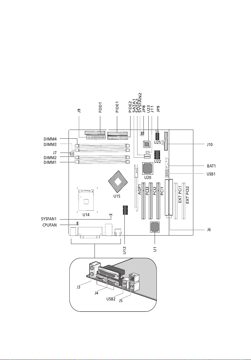
Mainboard layout
The mainboard becomes accessible once you open the system. It should
look like the figure shown below
Page 22

12
Item Description
AGP1 AGP slot
BAT1 Battery
CPUFAN CPU fan connector
2 System tour
DIMM1
DIMM2
DIMM3
DIMM4
FDD1 Floppy disc drive connector
J10 Front panel header
J11 Buzzer connector
J3 PS/2 KBMS
J4 Serial and Parallel ports
J5 Dual USB and RJ45
J6 Extended interface
J7 Power port and 12V power connector
J9 Main power connector
JP8 Clear CMOS
JP9
PCI1
PCI2
PCI3
DIMM slots
2
I
C feature connector
PCI slots
EXT PCI1
EXT PCI2
PIDE1
PIDE2
SATA1
SATA2
Extension PCI slots
Primary IDE connector
Secondary IDE connector
Serial ATA ports
Page 23

Item Description
13
SYSFAN1
SYSFAN2
U1 LAN controller
U12 Clock generator
U14 CPU slot (478 pin)
U15 875P chipset
U20 ICH5R chipset
U22 I/O controller
U23 BIOS
U25 Mini-BMC
USB1 Front USB connector
USB2 Dual USB connector
System fan connectors
Page 24

14
Jumper settings (JP8) clear CMOS
Pin Number Pin Definition
1Normal
2 Clear
3 Ground
1-2 Normal
2 System tour
2-3 Clear CMOS
Page 25
External and internal structure
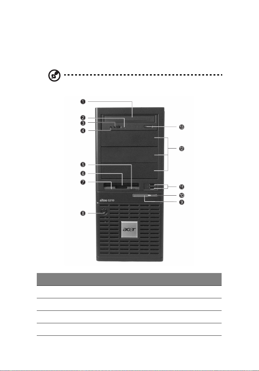
Front bezel
Note: One pair of system keys are provided (attached to the rear
panel of the system).
15
No. Description
1 CD-ROM drive
2 CD-ROM headphone port
3 CD-ROM volume control
4 CD-ROM activity indicator
Page 26

16
No. Description
5 FDD eject button
6 FDD (floppy disc drive)
7 FDD activity indicator
8 Security keylock
9 System power indicator
10 System power button
11 USB 2.0 ports (two)
12 5.25-inch half-height bays
13 CD-ROM stop/eject button
2 System tour
Page 27
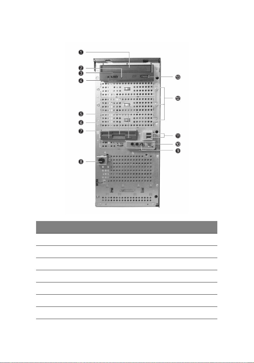
Front panel
17
No. Description
1 CD-ROM drive
2 CD-ROM headphone port
3 CD-ROM volume control
4 CD-ROM activity indicator
5 FDD eject button
6 FDD (floppy disc drive)
7 FDD activity indicator
Page 28

18
No. Description
8 Security keylock
9 System power indicator
10 System power button
11 USB 2.0 ports (two)
12 5.25-inch half-height bays
13 CD-ROM stop/eject button
2 System tour
Page 29
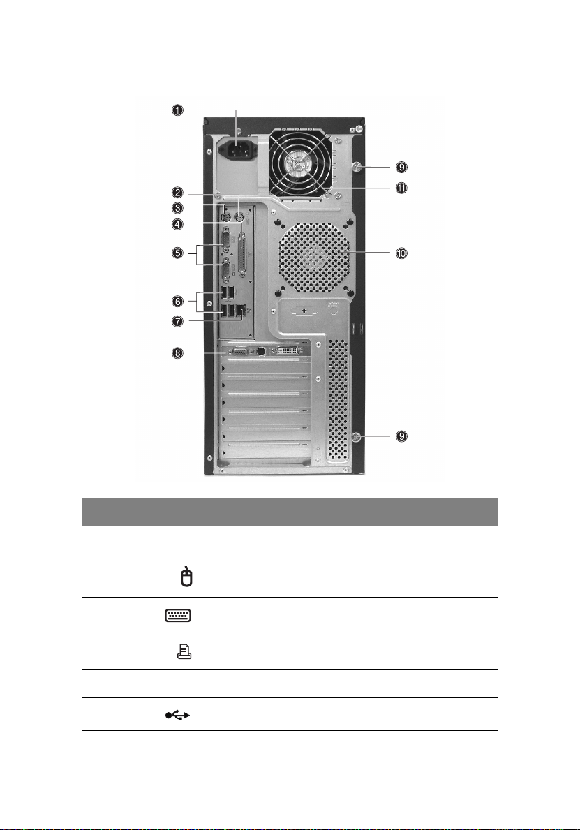
Rear panel
19
No. Icon Description
1 Main power supply unit
2 PS/2 mouse port
3 PS/2 keyboard port
4 Parallel/printer port
5 Serial ports (two)
6 USB 2.0 ports (four)
Page 30

20
No. Icon Description
7 Gigabit LAN port (10/100/1000 Mbps)
8 AGP add-on card (actual ports vary by configuration)
9 Side panel tool-less screws (top and bottom)
10 System ventilation/fan exhaust
11 Main power supply fan-exhaust
2 System tour
Page 31

Internal components
21
No. Description
1 Power supply unit
2 System fan
3 Mainboard
4 PCI bus slots
5 HDD bays
6 3.5” device bays
7 5.25” device bays
Page 32

22
2 System tour
Page 33

3 Getting Started
Page 34

This chapter gives information on setting up
and starting to use your system
Page 35

Setting up the system
Preinstallation requirements
Selecting a site
Before unpacking and installing the system, select a suitable site for
the system for maximum efficiency. Consider the following factors
when choosing a site for the system:
• Near a grounded power outlet
• Clean and dust-free
• Stable surface free from vibration
• Well-ventilated and away from sources of heat
• Secluded from electromagnetic fields produced by electrical
devices such as air conditioners, radio and TV transmitters, etc.
Checking the package contents
Check the following items from the package:
• Acer Altos G310 series system
• Acer Altos G310 series User’s guide
• Acer Altos G310 series Accessory box
• System keys (attached to the rear panel of the system)
25
If any of the above items are damaged or missing, contact your dealer
immediately.
Save the boxes and packing materials for future use.
Page 36

26
3 Getting Started
System startup
Turning on the system
After making sure that you have properly set up the system and
connected all the required cables, you can now power on the system.
To power on the system, press the power button on the front panel.
The system starts up and displays a welcome message. After that, a
series of power-on self-test (POST) messages appears. The POST
messages indicate if the system is running well or not.
Note: If the system does not turn on or boot after pressing the
power button, go to the next section for the possible causes of the
boot failure.
Aside from the POST messages, you can determine if the system is in
good condition by checking if the following occurred:
• Power indicator on the front panel lights up (green)
• Num Lock, Caps Lock, and Scroll Lock indicators on the keyboard
light up
Page 37

Turning off the system
To turn off the server, on the Windows task bar click on the Start
button, point to Shut Down..., select Shut down from the dropdown window then click on OK. You can then turn off all peripherals
connected to your server.
If you are unable to shutdown the server within Windows, press and
hold the power button for at least four seconds to force quit all
applications and shut down.
Power-on problems
If the system does not boot after you have applied power, check the
following factors that might have caused the boot failure.
• The external power cable may be loosely connected.
Check the power cable connection from the power source to the
power cable socket on the rear panel. Make sure that the cable is
properly connected to the power source and to the power cable
socket.
• No power comes from the grounded power outlet.
Have an electrician check your power outlet.
• Loose or improperly connected internal power cables.
Check the internal cable connections. If you are not confident to
perform this step, ask a qualified technician to assist you.
27
Warning! Make sure all power cords are disconnected from
the electrical outlet before performing this task.
Note: If you have gone through the preceding actions and the
system still fails to boot, ask your dealer or a qualified technician
for assistance.
Page 38

28
3 Getting Started
BIOS POST Checkpoint Codes
Bootblock Initialization Codes
The Bootblock initialization code sets up the chipset, memory
and other components before system memory is available. The
following table describes the type of checkpoints that may
occur during the bootblock initialization
Checkpoint Code Description
Before D1 Early chipset initialization is done. Early super I/O
initialization is done including RTC and keyboard
controller.
NMI is enabled.
.
D1 Perform keyboard controller BAT test. Checks if
D0 Go to flat mode with 4 GB limit and GA20 enabled.
D2 Disable CACHE before memory detection. Execute
D3 If memory sizing module not executed, start memory
D4 Test base 512 KB memory. Adjust policies and cache
D5 Bootblock code is copied from ROM to lower system
D6 Both Key sequence and OEM specific method is
waking up from power management suspend state.
Save power-on CPUID value in scratch CMOS.
Verify the bootblock checksum.
full memory sizing module. Verify that flat mode is
enabled.
refresh and do memory sizing in Bootblock code. Do
additional chipset initialization. Re-enable CACHE.
Verify that flat mode is enabled
first 8 MB. Set stack.
memory and control is given to it. BIOS now executes
out of RAM
checked to determine if BIOS recovery is forced. Main
BIOS checksum is tested. If BIOS recovery is necessary,
control flows to checkpoint E0. See Bootblock Recov-
ery Code Checkpoints for more information.
Page 39

Checkpoint Code Description
29
D7 Restore CPUID value back into register. The Boot-
D8 The Runtime module is uncompressed into memory.
D9 Store the Uncompressed pointer for future use in
DA Restore CPUID value back into register. Give control
block-Runtime interface module is moved to system
memory and control is given to it. Determine
whether to execute serial flash.
CPUID information is stored in memory.
PMM.
Copying Main BIOS into memory. Leaves all RAM
below 1MB Read-Write including E000 and F000
shadow areas but closing SMRAM.
to BIOS POST (ExecutePOSTKernel).
Bootblock Recovery Codes
The Bootblock recovery code gets control when the BIOS
determines that a BIOS recovery needs to occur because the
user has forced the update or the BIOS checksum is corrupt. The
following table describes the type of checkpoints that may
occur during the Bootblock recovery portion of the BIOS.
Checkpoint Code Description
E0 Initialize the floppy controller in the super I/O. Some
interrupt vectors are initialized. DMA controller is initialized 8259 interrupt controller is initialized. L1
cache is enabled.
E9 Set up floppy controller and data. Attempt to read
from floppy.
EA Enable ATAPI hardware. Attempt to read from ARMD
EB Disable ATAPI hardware. Jump back to checkpoint E9.
and ATAPI CDROM.
Page 40

30
Checkpoint Code Description
3 Getting Started
EF Read error occurred on media. Jump back to check-
E9 or EA Determine information about root directory of
F0 Search for pre-defined recovery file name in root
F1 Recovery file not found.
F2 Start reading FAT table and analyze FAT to find the
F3 Start reading the recovery file cluster by cluster.
F5 Disable L1 cache.
FA Check the validity of the recovery file configuration
FB Make flash write enabled through chipset and OEM
F4 The recovery file size does not equal the found flash
FC Erase the flash part.
point EB.
recovery media.
directory.
clusters occupied by the recovery file.
to the current configuration of the flash part.
specific method. Detect proper flash part. Verify that
the found flash part size equals the recovery file size.
part size.
FD Program the flash part.
FF The flash has been updated successfully. Make flash
write disabled. Disable ATA PI har d w are. Restore
CPUID value back into register. Give control to F000
ROM at F000:FFF0h.
Page 41

31
POST code checkpoints
The POST code checkpoints are the largest set of checkpoints
during the BIOS pre-boot process. The following table describes
the type of checkpoints that may occur during the POST portion
of the BIOS
Checkpoint Code Description
.
03 Disable NMI, Parity, video for EGA, and DMA control-
04 Check CMOS diagnostic byte to determine if battery
05 Initializes the interrupt controlling hardware (gener-
06 Do R/W test to CH-2 count reg. Initialize CH-0 as sys-
08 Initializes the CPU. The BAT test is being done on
lers. Initialize BIOS, POST, and Runtime data area.
Also initialize BIOS modules on POST entry and GPNV
area.
Initialized CMOS as mentioned in the Kernel Variable
"wCMOSFlags."
power is OK and CMOS checksum is OK. Verify CMOS
checksum manually by reading storage area.
If the CMOS checksum is bad, update CMOS with
power-on default values and clear passwords. Initialize status register A.
Initializes data variables that are based on CMOS
setup questions.
Initializes both the 8259 compatible PICs in the system
ally PIC) and interrupt vector table.
tem timer. Install the POSTINT1Ch handler. Enable
IRQ-0 in PIC for system timer interrupt. Traps INT1Ch
vector to "POSTINT1ChHandlerBlock."
KBC.
Program the keyboard controller command byte is
being done after Auto detection of KB/MS using AMI
KB-5.
C0 Early CPU Init Start -- Disable Cache - Init Local APIC
C1 Set up boot strap processor Information
Page 42

32
Checkpoint Code Description
C2 Set up boot strap processor for POST
C5 Enumerate and set up application predecessors
C6 Re-enable cache for boot strap processor
C7 Early CPU Init Exit
0A Initializes the 8042 compatible Keyboard Controller.
0B Detects the presence of PS/2 mouse.
0C Detects the presence of Keyboard in KBC port.
3 Getting Started
0E Testing and initialization of different Input Devices.
13 Early POST initialization of chipset registers.
24 Uncompress and initialize any platform specific BIOS
30 Initialize System Management Interrupt.
2A Initializes different devices through DIM.
2C Initializes different devices. Detects and initializes the
2E Initializes all the output devices.
31 Allocate memory for ADM module and uncompress
33 Initializes the silent boot module. Set the window for
Also, update the Kernel Variables.
Traps the INT09h vector, so that the POST INT09h han-
dler gets control for IRQ1. Uncompress all available
language, BIOS logo, and Silent logo modules.
modules.
video adapter installed in the system that have
optional ROMs.
it. Give control to ADM module for initialization. Initialize language and font modules for ADM.
Activate ADM module.
displaying text information.
37 Displaying sign-on message, CPU information, setup
key message, and any OEM specific information.
Page 43

Checkpoint Code Description
38 Initializes different devices through DIM.
39 Initializes DMAC-1 and DMAC-2.
3A Initialize RTC date/time.
3B Test for total memory installed in the system. Also,
Check for DEL or ESC keys to limit memory test. Display total memory in the system.
3C Mid POST initialization of chipset registers.
33
40 Detect different devices (Parallel ports, serial ports,
50 Programming the memory hole or any kind of imple-
52 Updates CMOS memory size from memory found in
60 Initializes NUM-LOCK status and programs the KBD
75 Initialize Int-13 and prepare for IPL detection.
78 Initializes IPL devices controlled by BIOS and option
7A Initializes remaining option ROMs.
7C Generate and write contents of ESCD in NVRam.
84 Log errors encountered during POST.
85 Display errors to the user and gets the user response
and coprocessor in CPU, etc.) successfully installed in
the system and update the BDA, EBDA, etc.
mentation that needs an adjustment in system RAM
size if needed.
memory test. Allocates memory for Extended BIOS
Data Area from base memory.
typematic rate.
ROMs.
for error.
87 Execute BIOS setup if needed / requested.
8C Late POST initialization of chipset registers.
Page 44

34
Checkpoint Code Description
8D Build ACPI tables (if ACPI is supported)
3 Getting Started
8E Program the peripheral parameters. Enable/Disable
90 Late POST initialization of system management inter-
A0 Check boot password if installed.
A1 Clean-up work needed before booting to OS.
A2 Takes care of runtime image preparation for differ-
A4 Initialize runtime language module.
A7 Displays the system configuration screen if enabled.
A8 Prepare CPU for OS boot including final MTRR values.
A9 Wait for user input at configure display if needed.
AA Uninstall POST INT1Ch vector and INT09h vector.
NMI as selected
rupt.
ent BIOS modules. Fill the free area in F000h segment
with 0FFh. Initializes the Microsoft IRQ Routing Table.
Prepares the runtime language module. Disables the
system configuration display if needed.
Initialize the CPU before boot, which includes the
programming of MTRR.
Reinitializes the ADM module.
AB Prepare BBS for Int 19 boot.
AC End of POST initialization of chipset registers.
B1 Save system context for ACPI.
00 Passes control to OS Loader (typically INT19h).
Page 45

35
Beep Codes
Beep codes are used by the BIOS to indicate a serious or fatal
error to the end user. Beep codes are used when an error occurs
before the system video has been initialized. Beep codes are
generated by the system board speaker. The following table
describes the beep codes that are used by BIOS:
Number of beeps Description
1 Memory refresh timer error.
3 Main memory read/write test error.
6 Keyboard controller BAT test error.
7 General exception error.
8 Display memory error.
Page 46

36
3 Getting Started
Page 47

4 Configuring
the system
Page 48

This chapter discusses the precautionary
measures and installation procedures you
need to know when upgrading the system.
Page 49

Upgrading the system
Certain components of the server are upgradeable such as the drives,
the CPU, the memory, and the expansion cards. However, for safety
purposes, we do not recommend that you perform these upgrades
yourself. If you want to replace or upgrade any of these components,
contact your dealer or a qualified service technician for assistance.
Important: Observe the installation precautions described in the
subsequent section when installing or removing a server
component.
39
Page 50

40
4 Configuring the system
Installation precautions
Before you install any server component, we recommend that you read
the following sections. These sections contain important ESD
precautions along with preinstallation and post-installation
instructions.
ESD precautions
Electrostatic discharge (ESD) can damage the processors, motherboard,
disk drives, expansion boards, or other components. Always observe
the following precautions before you install a server component:
1 Do not remove a component from its protective packaging until
you are ready to install it.
2 Wear a wrist grounding strap and attach it to a metal part of the
server before handling components. If a wrist strap is not
available, maintain contact with the server throughout any
procedure requiring ESD protection.
Page 51

Preinstallation instructions
Always observe the following before you install any component:
1 Turn off the system and all the peripherals connected to it.
2 Unplug all cables from the power outlets.
3 Open the system according to the instructions on page 42.
4 Follow the ESD precautions described in this section when
handling a server component.
5 Remove any expansion board(s) or peripheral(s) that block access
to the DIMM socket or other component connector.
See the following sections for specific installation instructions on the
component you want to install.
Warning! Failure to properly turn off the server before you
start installing components may cause serious damage. Do
not attempt the procedures described in the following
sections unless you are a qualified service technician.
Post-installation instructions
Observe the following after installing a server component:
1 See to it that all components are installed according to the
described step-by-step instructions.
2 Reinstall any expansion board(s) or peripheral(s) that you have
previously removed.
3 Reinstall the chassis panels.
4 Connect the necessary cables.
5 Turn on the system.
41
Page 52

42
4 Configuring the system
Opening the server
Caution! Before you proceed, make sure that you have turned off
your system and all peripherals connected to it. Read the
“Preinstallation instructions” on page 41.
You need to open the server before you can install additional
components. The front and left side panels are removable to allow
access to the system’s internal components. Refer to the following
sections for instructions.
Before opening the server
Before opening the server, observe the following precautions:
1 Turn off the system and all the peripherals connected to it.
2 Unplug all cables from the power outlets.
3 Place the system unit on a flat, stable surface.
Note: Because of the G310 design specification, only the side
panel needs to be removed to access the system board.
Page 53

To remove the side panel
The side panel is attached to the server by two (non-removable)
thumbscrews.
To remove the side panel:
1 Locate the System Keys (if necessary) and unlock the system lock
on the front panel.
2 Loosen the thumbscrews located at the rear end of the left
panel (1).
3 Slide the left panel rearward (2) before detaching it from the
chassis.
43
Page 54

44
4 Configuring the system
To remove the front panel
The front bezel is attached to the chassis by screwless hinges. To
remove the front panel, you must remove the side panel first.
To remove the front bezel:
1 With your finger, pull the Front Panel Release lever located at the
bottom front inside the chassis (1).
2 Gently pull the bottom of the Front bezel away from the chassis
(2), lift it to approximately 45 degrees, then detach the top and
move it away from the chassis.
Page 55

Installing and removing storage devices
The system supports 3.5-inch and 5.25-inch internal storage devices.
The system comes pre-installed with a floppy drive and a CD-ROM
drive. The empty 5.25-inch half-height bays allow you to install
additional drives such as another CD-ROM drive or a tape drive.
To install a 5.25-inch storage device
Note: If you are installing a new drive in an empty drive bay, skip
steps 2 to 4.
1 Observe the ESD precautions and pre-installation procedures
described on page 41.
2 Disconnect the power and IDE cables from the old drive.
3 Lift the plastic tab that secures the drive in the bay (1) and gently
pull it from the chassis (2).
45
Page 56

46
4 Configuring the system
4 Transfer the two tool-less locking rails (on either side of the old
drive) to the new drive module.
5 Insert the new CD-ROM drive into the drive bay until it locks into
place with an audible “click.”
6 Connect the power and IDE cables to the new drive.
7 Observe the post-installation instructions described on page 41.
Page 57

Upgrading the CPU
This section includes instructions for removing and installing a CPU.
To remove a CPU with heatsink
Before installing a new CPU in a socket, remove first any previously
installed CPU from that socket.
Important: Before removing a CPU from the mainboard, make
sure to create a backup file of all important data.
1 Observe the ESD precautions and pre-installation procedures
described on page 40.
2 Locate the CPU socket on the mainboard.
3 To remove the CPU and Heatsink assembly, follow the steps below:
a Locate the CPU FAN connector on the Mainboard and unplug the fan
before continuing.
b Release (1) and remove (2) the locking levers that secure the Heatsink
assembly to the mainboard.
c Remove the heatsink.
47
Page 58

48
4 Configuring the system
4 Follow the steps below to unlock and remove the CPU.
a Lift the CPU locking lever until it is fully extended.
b Gently unseat and pull the CPU from the socket.
Warning! The heatsink becomes very hot when the system
is on. NEVER touch the heatsink with any metal or with
your hands.
Page 59

To install a CPU with heatsink
1 Observe the ESD precautions and pre-installation procedures
described on page 40.
2 Locate the CPU socket on the mainboard.
3 Align the CPU to its socket, making sure that pin 1 (indicated by
the notched corner) of the CPU connects to hole 1 of the socket
(on the right corner in the image below).
4 To install the CPU to its socket, follow the steps below:
a Firmly insert the CPU into the socket.
b Lower the CPU locking lever to secure the processor.
49
Page 60

50
4 Configuring the system
5 After locking the CPU in place, follow the two remaining steps to
replace the heatsink and fan.
a Replace the heatsink on top of the CPU.
b Replace the locking levers by pressing down (1) and securing the clips
(2) to lock the heatsink assembly in place.
6 Reconnect the CPU FAN connector to the Mainboard. See
“Mainboard layout” on page 11 if you have difficult locating the
CPU FAN connector.
7 Observe the post-installation instructions described on page 41.
Page 61

Upgrading the system memory
Memory configuration
This section includes instructions for removing and installing a memory
module.
These tables (above and below) summarize the characteristics of 1-way
and 2-way memory interleave configurations with and without use of
dynamic mode.
51
Throughput level Memory configuration
4 (highest) 2-way memory interleave with dynamic mode
3 2-way memory interleave without dynamic mode
21-way memory interleave with dynamic mode
1 (lowest) 1-way memory interleave without dynamic mode
Warning! Functionality issues may be encountered if mixed
memory types are installed on the same server board. DIMM
modules of identical type, banking and stacking technology, and
vendor should be installed in the Altos G310.
Page 62

52
4 Configuring the system
To re m o v e a DIMM
Before installing a new DIMM in a socket, remove first any previously
installed DIMM from that socket.
Important: Before removing any DIMM from the mainboard,
make sure to create a backup file of all important data.
1 Observe the ESD precautions and pre-installation procedures
described on page 41.
2 Locate the DIMM socket on the mainboard.
3 Press the holding clips on both sides of the socket outward to
release the DIMM (1).
4 Gently pull the DIMM upward to remove it from the socket (2).
Note: Place your forefingers on the top of the DIMM before
pressing the holding clips to gently disengage the DIMM from the
socket.
Page 63

To install a DIMM
1 Observe the ESD precautions and pre-installation procedures
described on page 40.
2 Locate the DIMM sockets on the mainboard.
3 Open the clips on the socket.
4 Align then insert the DIMM into the socket (1).
5 Press the holding clips inward to lock the DIMM in place (2).
53
DIMMs must be installed in the following order: DM1. DM2, DM3 and DM4
Note: The DIMM socket is slotted to ensure proper installation.
If you insert a DIMM but it does not fit easily into the socket, you
may have inserted it incorrectly. Reverse the orientation of the
DIMM and insert it again.
6 Observe the post-installation instructions described on page 41.
Reconfiguring the system memory
The system automatically detects the amount of memory installed.
Run the BIOS setup to view the new value for total system memory and
make a note of it.
Page 64

54
4 Configuring the system
Installing an expansion card
This section explains how to install an expansion card. The onboard
expansion slots support PCI (Peripheral Component Interconnect)
cards.
Note: The BIOS setup automatically detects and assigns resources
to the new device (applicable only to Plug-and-Play expansion
cards).
To install an expansion card
Note: The illustrations used in this section show the Altos G310
server chassis.
1 Observe the ESD precautions and pre-installation procedures
described on page 40.
2 Remove the Side panel to access the mainboard. See page 43 for
more information.
3 Locate an empty expansion slot on the mainboard.
4 Remove the tool-less the card bracket lock(1).
Page 65

5 Pull out the card bracket (2).
6 Remove the expansion card from its protective packaging.
7 Align the card in the empty slot on the mainboard.
55
Page 66

56
4 Configuring the system
8 Insert the bracket with the card into the selected slot (3). Make
sure that the card is properly seated.
9 Secure the card with the tool-less bracket card lock removed in
step three above (4).
10 Observe the post-installation instructions described on page 41.
Page 67

Installing and removing a hard disk
Although the Altos G310 has four hard disk slots, the system board
only supports a maximum of three.
To re m o v e a hard d i s k
Follow these steps to replace your computer’s hard disk:
1 Remove the side and front panels (see page 43 and page 44).
2 Detach the cables from the exposed end of the HDD (1) and (2).
3 Squeeze the two locking tabs that secure the drive to the chassis
slot and gently remove the HDD from the system (3).
57
Page 68

58
4 Configuring the system
To install a hard disk
Observe the pre-installation and ESD precautions on page 40. Follow
these steps to replace your computer’s hard disk:
1 Remove the side panel (see page 43).
2 Attach the HDD rails to the sides of the drive housing.
3 Insert the drive into an empty HDD slot (slot 1 or slot 3) until it
locks into place with an audible “click” (1).
4 Attach the power and IDE cables to the HDD (2) and (3).
5 Replace the side cover and observe post-installation instructions as
explained on page 41.
Page 69

59
Configuring the SCSI/SCSI RAID HBA
This section briefly shows how to create a RAID 1 (mirror) volume. This
feature requires installation/presence of LSI Logic 20320-R or LSI Logic
22320-R U32 SCSI controllers.
How to use SCSI HBA setup utility
During the Power-On Self Test (POST), press <Ctrl > + <C> to enter the
LSI Logic Configuration Utility.
Loading HBA Default Settings
1 In the LSI Logic MPT SCSI Setup Utility, please press F2 and select
Global Properties. Then, select <Restore Defaults>.
2 Press ESC, then select <Save changes then exit this menu>.
3 Move cursor to <53C1020/1030> and press Enter
4 Move cursor to <Restore Defaults> and press Enter.
5 Press ESC, then select <Save changes then exit this menu>.
How to use SCSI RAID HBA setup utility
How To Create RAID 1 (Mirror) volume with a Hot Spare
Disk
1 In the LSI Logic MPT SCSI Setup Utility, please select <53C1020/
1030> and press Enter.
2 Move cursor to <RAID Properties> and press Enter.
3 In Array Disk field, press Space key to change the hard disk to
[Yes].
Note: In the Array Disk field, if you change settings, you will see
the following messages. Press the DELETE key to erase data.
F3 - keep Data (Create 2 disk array)
Delete - Erase Disk (Create 2 to 6 disk array)
4 In Hot Spare field, press Space key to change the hard disk to [Yes].
Page 70

60
Note: In the Hot Spare field, if you change settings, you will see
the following messages. Press the DELETE key to ignore it.
WARNING: Data on drive will be LOST!
Press DELETE if data loss OK or any other key to cancel.
5 Press ESC, then select <Save changes then exit this menu>.
4 Configuring the system
RAID Volume Initialization
After you create RAID volume and save the changes, the disk controller
will initialize RAID volume automatically. As LSI Logic 20320-R/22320-R
can support background initialization, you don’t have to wait for the
initialization to complete. Now, you can exit LSI Logic Configuration
Utility.
Exit and Restart the server
1 Press ESC, then select <Exit the Configuration Utility>. Then, you
will see a [Global properties saved. Hit any key to reboot.]
message.
2 Press a key to reboot system.
Page 71

61
MegaRAID Configuration Utility
Turn on the system power. When prompted, press <Ctrl> + <M> to
enter the MegaRAID Configuration Utility. After entering the
MegaRAID Configuration Utility, you will see the Management Menu
on the screen.
Load RAID Card Default Setting
1 Select Objects from Management menu.
2 Select Adapter from Objects. The adapter setting will be shown on
the screen. You can change the setting from this menu.
3 Select Factory Default and YES to load the default settings.
4 Press <Ctrl> + <Alt> + <Del> to reboot the server.
Create RAID1 Volume
1 After the server has rebooted, press <Ctrl> + <M> to enter the
MegaRAID Configuration Utility again.
2 Select Configuration from Management Menu.
3 Select New Configuration from the Configuration menu and select
YES to continue. An array selection window displays the devices
connected to the current controller.
4 Press the arrow keys to choose specific physical drives and press
spacebar to associate the selected drive with the current array. The
indicator for selected drive change from READY to ONLINE A[array
number]-[drive number]. For example, ONLINE A1-2 means disk
drive 2 in array 1.
5 Add 2 drives to current array and press <Enter> to finish creating
current array.
6 Press <F10> to configure the logical drives.
7 The default RAID level for 2 disk drives is RAID1. Just select Accept
to use the default setting and press <Enter> to return to the
ARRAY SELECTION MENU.
8 Press <Enter> to end the array configuration.
9 Select YES to Save Configuration and press any key to return to the
Configure menu.
Page 72

62
4 Configuring the system
Assign Hot Spare Disk
1 Select Add/View Configuration from Configuration menu.
2 Press arrow keys to choose specific physical drives and press <F4>
to set the drive as Hot Spare Disk. Select YES to confirm and the
indicator for selected drive change from READY to HOTSP.
3 Press <Esc> to end the array configuration.
4 Select YES to Save Configuration and press any key to return to the
Configure menu.
Initialize RAID Volume
1 Press <Esc> to return to the Management Menu.
2 Select Initialize from Management menu. All logical drives should
be listed under Logical Drives.
3 Press <Spacebar> to select drives for initialization. The selected
drive will be shown in yellow.
4 After selecting the drives, press <F10> and select YES to start the
initialization process.
5 When initialization is complete, press any key to continue.
6 Press <Esc> to return to the Management Menu.
Save And Exit MegaRAID Configuration Utility
1 When RAID configuration and initialization is complete, press
<Esc> in the Management Menu and select YES to exit the
MegaRAID Configuration Utility.
2 Press <Ctrl> + <Alt> + <Del> to reboot the server. Now you can
start installing an OS on the RAID array.
Page 73

Configuring Parallel ATA and Serial ATA devices
ATA Operate Mode
There are two modes to choose from: Legacy mode and Native mode.
1 Legacy Mode
• System BIOS assigns 14 and 15 IRQs for HDD use
• Older OSs that do not support Native Mode (DOS, Win2K, Win98/
ME...) should set S-ATA and P-ATA to Legacy Mode
• Maximum 4 ATA devices to connect under Combined mode or
Non-Combined mode
a Non-Combined Mode: S-ATA devices only - Maximum of 2 devices
b Non-Combined Mode: P-ATA devices only - Maximum of 4 devices
c Combined Mode: S-ATA devices and P-ATA devices - 2 devices each
(Maximum of 4 devices)
2 Native Mode
• System BIOS will search all available IRQs for HDD use
• New OSs that support Native Mode (Windows® XP Professional,
Windows® 2000, and Windows® Server 2003) can set S-ATA and PATA to Native Mode
• Comprehend both Legacy and/or Native Modes
• Maximum of 6 devices can be connected (4 P-ATA and 2 S-ATA)
63
Note: Proper support; BIOS provides a BIOS setup option for user
selection of Native Mode or Legacy Mode.
Page 74

64
4 Configuring the system
Intel ICH5R Serial ATA RAID introduction
The south bridge ICH5R provides a hybrid solution that combines two
independent SATA ports for support of up to two Serial ATA (Serial ATA
RAID) drives.
Serial ATA (SATA) is the latest generation of the ATA interface. SATA
hard drives deliver transfer speeds of up to 150MB/sec.
• Supports 150 MB/s transfers with CRC error checking
• Data handling optimization including tagged command queuing,
elevator seek and packet chain command
Parallel ATA and Serial ATA device configurations supported by Intel ICH5R
ATA Operate Mode BIOS configuration
The Intel RAID Option ROM should be integrated with the system BIOS
on all motherboards with a supported Intel chipset. Press <Ctrl> + <I>
to enter the Intel
appear early in system boot-up, during the POST (Power-On Self Test).
(R)
RAID for Serial ATA status screen, which should
Using the Intel RAID Option ROM
Creating, Deleting and Resetting RAID Volumes
The Serial ATA RAID volume may be configured using the RAID
Configuration utility located on the Intel RAID Option ROM. During
Page 75

65
the Power-On Self Test (POST), the following screen will appear for a
few seconds:
Note: The “Drive Model,” “Serial #,” and “Size” shown in the
above example may differ from your system configuration.
When the above message appears, press <Ctrl> + <I> simultaneously to
enter the RAID Configuration Utility.
After pressing the <Ctrl> + <I> keys simultaneously, the following
window will appear:
Page 76

66
4 Configuring the system
Option 1: Create RAID Volume
To create a RAID volume, select this option on the screen and press
<Enter>. The following screen will appear:
Note: The following procedure is only available with a newly-built
system or if you are reinstalling your OS. It should not be used to
migrate an existing system to RAID 0.
Specify a RAID Volume name and then press the <TAB> or <Enter> key
to go to the next field.
Page 77

67
Select the strip value for the RAID 0 array by scrolling through the
available values by using the “up arrow” or “down arrow” keys. Press
the <Enter> key to select and advance to the next field.
The available values range from 4KB to 128 KB in power of 2
increments. The strip value should be chosen based on the planned
drive usage. Here are some suggested selections:
• 16 KB - Best for sequential transfers
• 64 KB - Good general purpose strip size
• 128 KB - Best performance for most desktops and workstations
The default strip size is 128 KB.
From the Strip size, press the <Tab> or <ENTER> key to advance to the
Create Volume prompt. The window will appear as follows:
Page 78

68
4 Configuring the system
Press <Enter> to create the specified volume and the following prompt
will show:
Press <Y> to confirm the selection or press <N> to previous screen to
create the RAID volume again.
Then you will return to the main menu with an updated status as
shown below:
Page 79

69
Scroll to option 4 Exit and press <Enter> to exit the RAID Configuration
utility. The following prompt appears:
Press <Y> to confirm and exit or <N> to previous screen.
Option 2: Delete RAID Volume
Here you can delete the RAID volume, but please note that all data
including settings on RAID drives will be lost.
Note: If your system currently boots to RAID and you delete the
RAID volume in the Intel RAID Option ROM, your system will
become unbootable.
Page 80

70
4 Configuring the system
Select option 2 Delete RAID Volume from the main menu window and
press <Enter> to select a RAID volume for deletion. The following
window will appear:
Select a volume and press <Del> to delete the RAID volume. The
following prompt appears:
Press <Y> to delete the selected volume.
Page 81

71
Option 3: Reset Disks to Non-RAID
Select option 3 Reset Disks to Non-RAID and press <Enter> to delete
the RAID volume and remove any RAID structures from the drives. The
following screen appears:
Press <Y> key to accept the selection.
Note: You will lose all data on the RAID drives and any internal
RAID structures when you perform this operation.
Note: This operation may cause some issues such as incompatible
RAID configuration, a failed volume or failed disk.
Installation of Intel Application Accelerator RAID Utility
The Intel® Application Accelerator RAID Edition is the software
package that enables high-performance RAID 0 or RAID 1 arrays in
Windows® XP. This version of Intel® Application Accelerator contains
the following key features:
• Serial ATA RAID driver for Windows® XP/2000/Server 2003
• Intel® Application Accelerator RAID Edition utility
• Migration Feature
Page 82

72
4 Configuring the system
Insert the Acer System CD and click on the "Intel IAA RAID Edition" to
install the software.
The InstallShield Wizard will automatically begin the installation
process.
Click on the Next button to proceed from the installation welcome
window.
Page 83

73
After reading the license agreement in the following window, click Yes
button to continue.
Select the folder in which you want the program to be installed in the
following window, and click Next button to start installation.
Page 84

74
4 Configuring the system
Select a program folder in the following window where you want
Setup to add the program icon. Default is "Intel Application
Accelerator RAID Edition."
The following window appears to show the Intel Application
Accelerator RAID Edition Setup installation progress.
Page 85

75
Once the installation is complete, the following window appears.
Click the Finish button to end the installation and exit the setup utility.
RAID migration instructions
The Intel Application Accelerator RAID Edition offers the flexibility to
upgrade from a single Serial ATA (SATA) hard drive to a two drive
RAID-0 configuration when an additional SATA hard drive is added to
the system. This process will create a new RAID volume from an
existing disk. However, several important steps must be followed at the
time the system is first configured in order to take advantage of RAID
when upgrading to a second SATA hard drive.
• BIOS must be configured for RAID before installing Windows® XP/
2000/Server 2003 on the single SATA hard drive.
• Install the Intel Application Accelerator RAID driver during
Windows Setup.
• Install the Intel Application Accelerator RAID Edition after the
operating system is installed.
Note: A Create from Existing Disk operation will delete all
existing data from the added disk and the data cannot be
recovered. It is critical to backup all important data on the added
Page 86

76
disk before proceeding. During the migration process, the data on
the source disk will be preserved.
4 Configuring the system
Create RAID Volume from Existing Disk
To create a RAID volume from an existing disk, right-click on "RAID
Volume" and select "Create From Existing Disk" to create a new RAID
volume as shown in the screen below. You may also use the RAID dropdown menu and click on "Create Volume from Existing Disk."
1 Select the source disk that you wish to use and then click Next.
Important: It is very important to note which disk is the source disk
(the one containing all of the information to be migrated) and
which one is the target disk. On a RAID Ready system, this can be
determined by making a note during POST of which port (e.g. Port
0 or Port 1) the single disk is attached to. You can also use the Intel
Page 87

Application Accelerator RAID Edition utility before the second disk
is installed to verify the Port and serial number of the drive that
contains all the data.
2 Select the RAID volume name and strip size, and click Next.
• RAID Volume Name - A desired RAID volume name needs to be
typed in where the RAID_Volume1 text is shown above. The RAID
volume name has a maximum limit of 16 characters. The RAID
volume name must be in English alphanumeric ASCII characters.
• Strip Size - Select the desired strip size setting. As indicated, the
optimal setting is 128KB. Selecting any other option may result in
performance degradation. Even though 128KB is the
recommended setting for most users, you should choose the strip
size value which is best suited to your specific RAID usage model.
The most typical strip size settings are:
• 4KB: For specialized usage models requiring 4KB strips
• 8KB: For specialized usage models requiring 8KB strips
• 16KB: Best for sequential transfers
• 32KB: Good for sequential transfers
• 64KB: Good general purpose strip size
• 128KB: Best performance for most desktops and workstations
77
Before you continue to Step 3 (by clicking Next in Step 2), read the next
2 dialog boxes carefully. Please note that once you have selected
Migrate in Step 3, the Intel Application Accelerator RAID Edition will
have claimed the disks to be used in creating a new volume and this
Page 88

78
operation cannot be undone. It is critical that you backup all important
data before selecting Yes to these dialog boxes:
3 Confirm the creation of new RAID volume
In Step 3, confirm the creation of the new RAID volume and then click
Migrate:
4 Configuring the system
Migration Process
The migration process may take up to two hours to complete
depending on the size of the disks being used and the strip size
selected.
A dialog window will appear stating that the migration process may
take considerable time to complete and you must click Yes in order to
start the migration.
Page 89

79
While you can still continue using your computer during the migration
process, once the migration process starts, it cannot be stopped. If the
migration process gets interrupted and your system is rebooted for any
reason, it will pick up the migration process where it left off.
You will be provided with an estimated completion time (the
remaining time will depend on your system) once the migration
process starts as illustrated in the following example:
The following screen appears if the migration process is completed
successfully. Then you have to reboot your system to use the full
capacity of the new volume.
Page 90

80
4 Configuring the system
Page 91

5 BIOS setup
Page 92

This chapter gives information about the
system BIOS and discusses how to configure
the system by changing the settings of the
BIOS parameters.
Page 93

83
BIOS setup
BIOS setup is a hardware configuration program built into your
system's Basic Input/Output System (BIOS). Since most systems are
already properly configured and optimized, there is no need to run this
utility. You will need to run this utility under the following conditions:
• When changing the system configuration
• When a configuration error is detected by the system and you are
prompted ("Run Setup" message) to make changes to the BIOS
setup
Note: If you repeatedly receive Run Setup messages, the battery
may be bad. In this case, the system cannot retain configuration
values in CMOS. Ask a qualified technician for assistance.
• When redefining the communication ports to prevent any conflicts
• When making changes to the Power Management configuration
• When changing the password or making other changes to the
security setup
BIOS setup loads the configuration values in a battery-backed
nonvolatile memory called CMOS RAM. This memory area is not part
of the system RAM which allows configuration data to be retained
when power is turned off.
Before you run BIOS setup, make sure that you have saved all open
files. The system reboots immediately after you close setup.
Page 94

84
5 BIOS setup
Entering BIOS setup
Power on the server to start the system POST (Power On Self Test)
process. During bootup, press F2 to enter the BIOS setup screen.
Note: You must press F2 while the system is booting. This key
combination does not work during any other time.
There are several tabs on the setup screen corresponding to the six
major BIOS menus:
•Main
•Advanced
•Power
• Boot
•Security
• Exit
The parameters on the screens shown in this User’s guide display
default system values. These values may not be the same as those in
your system.
Note the following reminders when moving around the setup screen:
•Use the Left and Right arrow keys to move to the next page or to
return to the previous screen.
• Use the Up and Down arrow keys to select an item.
• Use the + and - keys to select an option.
Note: You can configure a parameter that is enclosed in square
brackets. Grayed-out items have fixed settings and are not
user-configurable.
• Use the Ta b key to select a field.
Page 95

85
• Use the Enter key to display a submenu screen.
Note: When a parameter is preceded by a (>), it means that a
submenu screen is available.
• Press F1 for General Help on using the BIOS setup.
• Press F10 to save changes and close the BIOS setup.
• Press Esc to close the BIOS setup.
In the descriptive table following each of the screen illustrations,
settings in boldface are the default and suggested parameter settings.
Page 96

86
5 BIOS setup
Main
The Main menu displays basic and important information about the
system. These information is necessary for troubleshooting and may
be required when asking for technical support.
The last two parameters on the screen lets you define the system’s time
and date settings. The real-time clock keeps the system date and time.
After setting the date and time, you do not need to enter them every
time you turn on the system. As long as the internal battery remains
good and connected, the clock continues to keep the date and time
accurately even when the power is off.
Parameter Description
BIOS Build Date Date when the BIOS setup was created
BIOS Version ID number of the BIOS setup
SMBIOS Version SMBIOS version of BIOS
Page 97

Parameter Description
87
System Time Sets the time following the hour-minute-second
System Date Sets the date following the weekday-month-day-
format. Valid values for hour, minute, and second
are:
Hour: 00 to 23
Minute: 00 to 59
Second: 00 to 59
year format. Valid values for weekday, month, day,
and year are:
Weekday: Sun, Mon, Tue, Wed, Thu, Fri, Sat
Month: 1to 12.
Day: 1 to 31
Year: 1980 to 2079
Page 98

88
5 BIOS setup
Advanced
The Advanced menu contains parameter values that define how the
system behaves on startup.
Warning! Be cautious in setting parameter values in the
Advanced menu as any incorrect value may cause the
system to malfunction.
Press Enter to enter the submenu screen of the parameters shown in
the screen below.
Page 99

Peripheral Configuration
The Peripheral Configuration submenu lets you define the parameter
settings for the system’s parallel and serial ports.
89
Parameter Description
Serial Port A
(Address/IRQ)
Serial Port B
(Address/IRQ)
Parallel Port
Address
Parallel Port
Mode
Serial port 1 address and IRQ (interrupt request) setting
Serial port 2 address and IRQ (interrupt request) setting
Sets a logical base address for the parallel port
Sets the operation mode for the parallel port
Page 100

90
Parameter Description
5 BIOS setup
Parallel Port
IRQ
Assigns an IRQ for the parallel port.
If you install an add-on card that has a parallel port
whose address conflicts with the onboard parallel port, a
warning appears on the screen. Check the parallel port
address of the add-on card and change the address to
one that does not conflict.
 Loading...