

Page 1

Maintenance Manual
Extensa 57x Series
Notebook Computers
9811323-0001
May 1996
Page 2

Copyright (©) 1996 Texas In struments Incorporated
All Rights Reserved — Printed in U.S.A.
Extensa 57x Series Notebook Computers
Maintenance Manual
TI Part No. 9811323-0001
Original Issue: May 1996
Changes may be made periodically to the information in this publication.
Such changes will be incorporated in new editions of this manual.
No part of this publication may be reproduced, stored in a retrieval system,
or transmitted, in any form or by any means, electronic, mechanical,
photocopy, recording, or otherwise, without the prior written permission of
Texas Instruments Incorporated.
The equipment, as well as the programs that TI has created to use with
them, are tools that can help people better manage the information used in
their business; but too ls — i nc luding TI products — cann o t replace sound
judgment nor make the manager’s business decisions.
Consequently, TI cannot warrant that its products are suitable for any specific customer application. The manager must rely on judgment of what is
best for his or her business.
Address all correspondence regarding orders to:
Texas Instruments Incorporated
P.O. Box 6102, M/S 3255
Temple, Texas 76503
Extensa and DockMate are trademarks of Texas Instruments.
The icons in the Windows Notebook and Startup groups are copyrighted
by Texas Instruments.
Lotus is a trademark of Lotus Development Corporation.
IBM and VGA are trademarks and PS/2 is a registered trademar k of International
Business Machines Corporation.
Microsoft, Windows, and MS-DOS are registered trademarks of Microsoft
Corporation.
Intel and Pentium are registered trademarks of Intel Corporation.
Cirrus and SimulSCAN are trademarks of Cirrus Logic, Inc.
IRDA is a trademark of Infra Red Data Association.
Page 3

Preface
1 General Description
1.1 . . . . Introduction . . . . . . . . . . . . . . . . . . . . . . . . . . . . . . . 1-1
1.2 . . . . Product Models . . . . . . . . . . . . . . . . . . . . . . . . . . . . . 1-1
1.3 . . . . International Product Ve rsions . . . . . . . . . . . . . . . . . 1-2
1.4 . . . . Product Overview . . . . . . . . . . . . . . . . . . . . . . . . . . . 1-3
1.4.1 . . . External Ports . . . . . . . . . . . . . . . . . . . . . . . . . . . 1-5
1.4.2 . . . Glidepad Pointing Device . . . . . . . . . . . . . . . . . . . 1-6
1.4.3 . . . Keyboard . . . . . . . . . . . . . . . . . . . . . . . . . . . . . . . 1-6
1.4.4 . . . Standard Power Features . . . . . . . . . . . . . . . . . . . 1-7
1.4.5 . . . Wireless Connection With Serial Infrared Port . . . 1-8
1.4.6 . . . Preloaded Software. . . . . . . . . . . . . . . . . . . . . . . . 1-8
Contents
1.4.7 . . . Notebook Expansion Capabilities . . . . . . . . . . . . . 1-8
1.5 . . . . Standard Test Features . . . . . . . . . . . . . . . . . . . . . . 1-9
1.6 . . . . Notebook Assemblies and Subassemblies . . . . . . . . . 1-9
1.6.1 . . . Cover-Display Assembly. . . . . . . . . . . . . . . . . . . . 1-10
1.6.2 . . . System Base Assembly. . . . . . . . . . . . . . . . . . . . . 1-11
1.7 . . . . Extensa 57x Series Notebook Specifications . . . . . . . 1-11
1.8 . . . . Agency Approvals . . . . . . . . . . . . . . . . . . . . . . . . . . . 1-13
2 Installation
2.1 . . . . Introduction . . . . . . . . . . . . . . . . . . . . . . . . . . . . . . . 2-1
2.2 . . . . Unpacking Instructions. . . . . . . . . . . . . . . . . . . . . . . 2-1
2.3 . . . . Installing Notebook Options . . . . . . . . . . . . . . . . . . . 2-1
2.3.1 . . . Installing Expansion Memory Modules . . . . . . . . 2-1
2.3.2 . . . Installing PCMCIA Options . . . . . . . . . . . . . . . . . 2-2
2.3.3 . . . Installing the Optional Numeric Keypad . . . . . . . 2-2
2.4 . . . . Installing the Battery Pack(s) . . . . . . . . . . . . . . . . . . 2-2
2.5 . . . . Installing External Devices . . . . . . . . . . . . . . . . . . . . 2-3
Contents
iii
Page 4

2.5.1 . . . Installing an External Keyboard/Mouse . . . . . . . 2-4
2.5.2 . . . Installing External Parallel Printer . . . . . . . . . . . . 2-6
2.5.3 . . . Installing External Serial Port Device . . . . . . . . . 2-7
2.5.4 . . . Installing External SVGA Monitor . . . . . . . . . . . . 2-8
2.5.5 . . . Installing SIR Devices. . . . . . . . . . . . . . . . . . . . . . 2-9
2.6 . . . . Installing the AC Power Adapter . . . . . . . . . . . . . . . 2-10
2.7 . . . . Initial System Checkout . . . . . . . . . . . . . . . . . . . . . . 2-10
2.8 . . . . Configuring the System. . . . . . . . . . . . . . . . . . . . . . . 2-11
2.9 . . . . Making Backups of System Software. . . . . . . . . . . . . 2-11
2.10 . . . Loading Application Software . . . . . . . . . . . . . . . . . . 2-11
3 Operating Instructions
3.1 . . . . Introduction . . . . . . . . . . . . . . . . . . . . . . . . . . . . . . . 3-1
3.2 . . . . Notebook Controls and Indicators . . . . . . . . . . . . . . . 3-1
3.2.1 . . . LCD Contrast Control . . . . . . . . . . . . . . . . . . . . . 3-2
3.2.2 . . . Button Switches. . . . . . . . . . . . . . . . . . . . . . . . . . 3-2
3.2.3 . . . Cover Release Latch . . . . . . . . . . . . . . . . . . . . . . . 3-2
3.2.4 . . . Glidepad Controls . . . . . . . . . . . . . . . . . . . . . . . . 3-2
3.3 . . . . Operating Procedures . . . . . . . . . . . . . . . . . . . . . . . 3-2
3.3.1 . . . Floppy Drive Operating Procedures . . . . . . . . . . . 3-2
3.3.2 . . . Installing/Removing PCMCIA Options . . . . . . . . . 3-4
3.3.3 . . . Computer Hot Keys . . . . . . . . . . . . . . . . . . . . . . . 3 -4
3.3.4 . . . Responding to Low Battery Conditions. . . . . . . . . 3-4
3.3.5 . . . Minimizing Power Usage. . . . . . . . . . . . . . . . . . . . 3-4
3.3.6 . . . Recharging the Battery Packs. . . . . . . . . . . . . . . . 3-5
3.3.7 . . . Conditioning the Primary Battery. . . . . . . . . . . . . 3-5
3.3.8 . . . Restoring Missing System Files . . . . . . . . . . . . . . 3-5
3.3.9 . . . Rebuilding the System Software. . . . . . . . . . . . . . 3-5
4 Theory of Operation
iv
Contents
4.1 . . . . Introduction . . . . . . . . . . . . . . . . . . . . . . . . . . . . . . . 4-1
4.2 . . . . Notebook Functional Description. . . . . . . . . . . . . . . . 4-1
4.2.1 . . . Processor/Memory Subsystems . . . . . . . . . . . . . 4-1
4.2.2 . . . I/O Subsystem. . . . . . . . . . . . . . . . . . . . . . . . . . . 4-5
4.2.3 . . . Video Subsystem. . . . . . . . . . . . . . . . . . . . . . . . . 4-6
Page 5

4.2.4 . . . Hard Disk Subsystem . . . . . . . . . . . . . . . . . . . . . 4-6
4.2.5 . . . Floppy Diskette Drive Subsystem. . . . . . . . . . . . . 4-7
4.2.6 . . . CD-ROM Subsystem . . . . . . . . . . . . . . . . . . . . . . 4-7
4.2.7 . . . PCMCIA Subsystem . . . . . . . . . . . . . . . . . . . . . . . 4-7
4.2.8 . . . Sound Subsystem (Model Dependent) . . . . . . . . . 4-8
4.2.9 . . . Power Subsystem. . . . . . . . . . . . . . . . . . . . . . . . . 4-8
5 Troubleshooting Procedures
5.1 . . . . General . . . . . . . . . . . . . . . . . . . . . . . . . . . . . . . . . . . 5-1
5.2 . . . . Overview of Fault Isolation Process . . . . . . . . . . . . . . 5-1
5.3 . . . . Troubleshooting Procedures . . . . . . . . . . . . . . . . . . . 5-3
5.3.1 . . . Troubleshooting a Power Supply Problem. . . . . . . 5-3
5.3.2 . . . Troubleshooting a Display Problem . . . . . . . . . . . 5-5
5.3.3 . . . Fault Isolation Using Self Test . . . . . . . . . . . . . . . 5-5
5.3.4 . . . PCMCIA Modem Problems . . . . . . . . . . . . . . . . . . 5-5
5.3.5 . . . Fault Isolation Using Diagnostics . . . . . . . . . . . . 5 -6
6 Field Service
6.1 . . . . Introduction . . . . . . . . . . . . . . . . . . . . . . . . . . . . . . . 6-1
6.2 . . . . Preventive Maintenance. . . . . . . . . . . . . . . . . . . . . . . 6-1
6.2.1 . . . Cleaning the Computer . . . . . . . . . . . . . . . . . . . . 6-1
6.2.2 . . . Protecting the Disk Drives . . . . . . . . . . . . . . . . . . 6-1
6.2.3 . . . Handling the Computer Battery Pack . . . . . . . . . . 6-2
6.2.4 . . . Restoring System Software. . . . . . . . . . . . . . . . . . 6-2
6.3 . . . . Required Tools and Equipment . . . . . . . . . . . . . . . . 6-2
6.4 . . . . Notebook Field-Replaceable Parts and Assemblies. . . 6-3
6.4.1 . . . Cover-Display Assembly. . . . . . . . . . . . . . . . . . . . 6-3
6.4.2 . . . System Base Assembly. . . . . . . . . . . . . . . . . . . . . 6-5
6.5 . . . . FRU Removal and Replacement Procedures. . . . . . . . 6-8
6.5.1 . . . Removing/Replacing the Notebook Battery Pack . 6-8
6.5.2 . . . Removing/Replacing the Floppy Drive/CD-ROM . 6-8
6.5.3 . . . Removing/Replacing the Hard Drive . . . . . . . . . . 6-9
6.5.4 . . . Removing/Replacing DIMM Modules . . . . . . . . . . 6-9
6.5.5 . . . Removing/Replacing the Keyboard Assembly . . . 6-10
6.5.6 . . . Removing/Replacing the Display Assembly . . . . . 6-11
Contents
v
Page 6

6.5.7 . . . Removing and Replacing the LCD Status
. . . . . . . Assembly . . . . . . . . . . . . . . . . . . . . . . . . . . . . . . . 6-11
6.5.8 . . . Removing/Replacing the Top Case Assembly . . . . 6-12
6.5.9 . . . Removing/Replacing the Glidepad Assembly . . . . 6-12
6.5.10 . . Removing/Replacing the IR/Sound Assembly . . . 6-12
6.5.11 . . Removing/Replacing the Power Supply Board . . . 6-13
6.5.12 . . Removing/Replacing the CMOS Battery . . . . . . . 6-13
6.5.13 . . Removing/Replacing the Main Board . . . . . . . . . . 6-13
6.5.14 . . Removing/Replacing HDD Connector Board . . . 6-14
6.5.15 . . Removing/Replacing Inverter Board . . . . . . . . . . 6-15
A Self Test Erro r Messages
A.1 . . . . Introduction . . . . . . . . . . . . . . . . . . . . . . . . . . . . . . . A-1
B PC-Doctor Diagnostics
B.1 . . . . Introduction . . . . . . . . . . . . . . . . . . . . . . . . . . . . . . . B-1
B.2 . . . . Starting PC-Doctor . . . . . . . . . . . . . . . . . . . . . . . . . . B-1
B.3 . . . . Keyboard Navigation . . . . . . . . . . . . . . . . . . . . . . . . . B-2
B.4 . . . . Mouse Navigation . . . . . . . . . . . . . . . . . . . . . . . . . . . B-2
B.5 . . . . PC-Doctor Menus . . . . . . . . . . . . . . . . . . . . . . . . . . . B-3
B.5.1 . . . Online Help (?) . . . . . . . . . . . . . . . . . . . . . . . . . . . B-3
B.5.2 . . . Diagnostics . . . . . . . . . . . . . . . . . . . . . . . . . . . . . B-3
B.5.3 . . . Interactive Tests Menu. . . . . . . . . . . . . . . . . . . . . B-4
B.5.4 . . . Hardware Info Menu . . . . . . . . . . . . . . . . . . . . . . B-4
B.5.5 . . . Utility Menu. . . . . . . . . . . . . . . . . . . . . . . . . . . . . B-5
B.6 . . . . Quitting PC-Doctor . . . . . . . . . . . . . . . . . . . . . . . . . . B-6
B.7 . . . . Remote Operation . . . . . . . . . . . . . . . . . . . . . . . . . . . B-6
vi
Contents
Page 7

Preface
Introduction
This manual provides installation, operation and servicing data for the
Extensa 57x Series Notebook Computers.
Intended Audience
This manual is primarily intended for use by qualified service technicians
but contains information useful to non-te chnical users.
Contents
This manual contains six sections and reference a ppendices including:
Section 1: General Description —
•
notebook; provides a list of physical and electrical specifications.
Section 2: Installation —
•
cable up the notebook computer in a desktop environment.
Section 3: Operating Instructions —
•
operating controls and indicators and basic operating procedures.
Section 4: Theory of Operation —
•
for Extensa 57x Series Notebook Computers.
Section 5: Troubleshooting Procedures
•
performing fault isolation on the Extensa 57x Series Notebook
Computers.
Section 6: Field Service
•
maintenance procedures for the notebook computer.
Appendix A: Self Test Error Messages
•
Appendix B: PC-Doctor Diagnostics
•
Describes ho w to unpack, install options and
— Provides p r eventive and co r rective
Introduces the main features of the
Describes the no tebook
Describes the theory of operation
— Provides guidelines for
Preface
vii
Page 8

Other Manuals About the System
The following docu ments provide addi ti o nal information related to the
Extensa 57x Series Notebooks:
Extensa 57x Series Notebook Computer User’s Reference Manual,
•
contains reference information regarding the Extensa 57x series
software.
Windows 95® Help
•
PC-Doctor Help and Technical Reference
•
(online)
(online)
Ordering Parts and Supplies
To order a copy of any TI publication or to order option kits, spare parts or
supplies for your system, contact your TI Reseller or:
Telephone Toll-fr ee:
1-800-TI TEXAS
viii
Preface
Page 9
1
General Description
1.1
This manual contains field and factory level servicing information for the
Texas Instruments Ex tensa
1-1).
This section pr ovides a genera l overview and specifications for the Extensa
57x Series Notebook Computers.
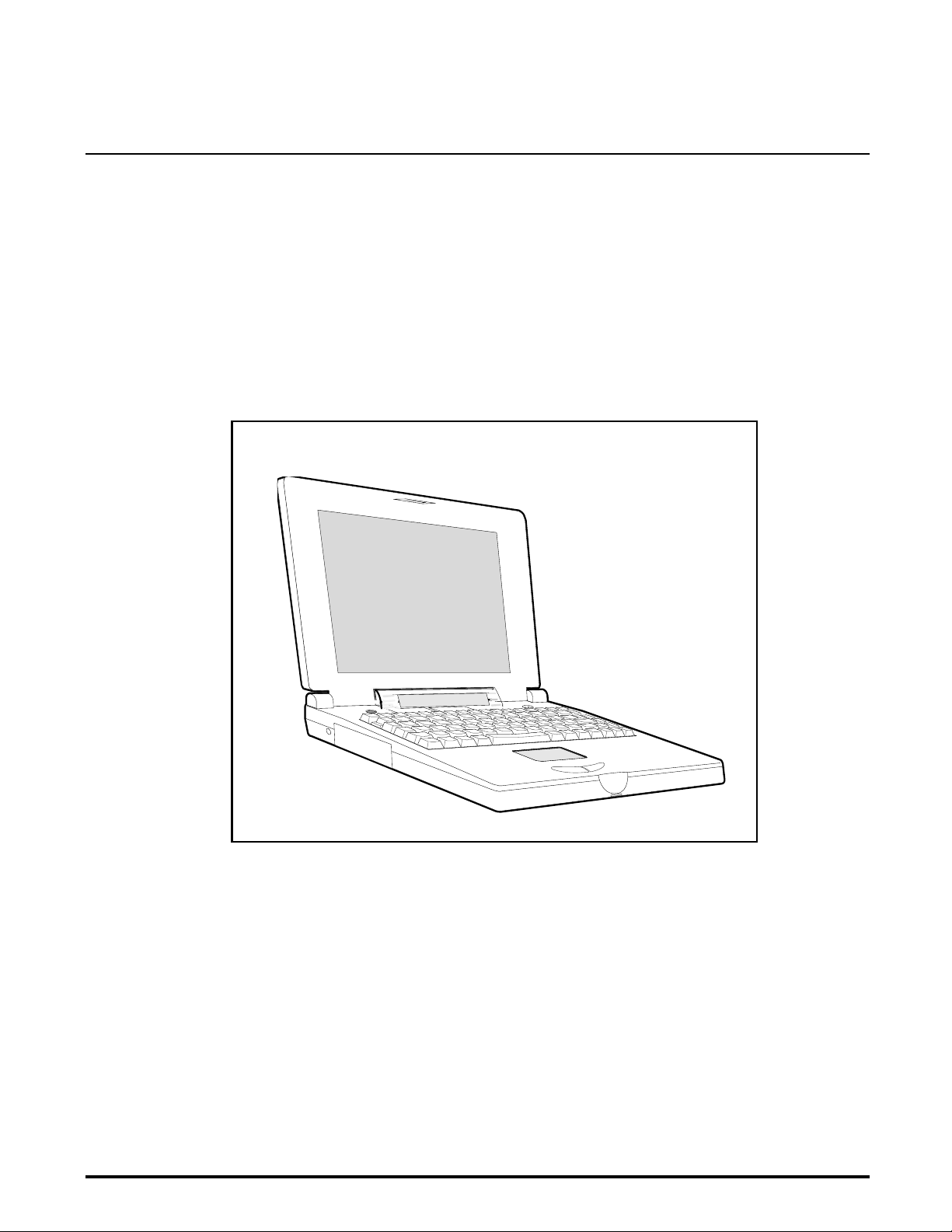
Introduction
57x Series of Notebook Computers (Figure
Figure 1-1 Extensa 57xSeries Notebook Computer
1.2
Table 1-1 summarizes the features shipped with the notebook for the
product models initially available in the Extensa 57x family of notebook
computers. The product models offer a choice of either 11.3 inch, dual scan
color or 10.4 inch active matrix color LCD and a choice of either the basic
Windows
Other options include choice of 810 million byte or 1200 million byte hard
drive.
Product Models
®
95 operating system or Windows 95 plus application softw a re.
General Description
1-1
Page 10
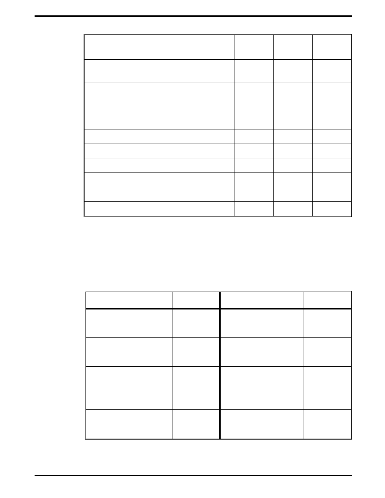
Table 1-1 Extensa 57x Series Notebook Computers
Features Model
570CD
11.3" Dual Scan, SVGA
Color LCD
10.4" Active Matrix (TFT),
SVGA Color LCD
1.44 MB Floppy Drive
Module
CD-ROM Drive Module X X X X
Windows
Applicatio n Software X X
16-Bit Stereo Sound X X X X
HDD 810 Million Bytes X X
HDD 1200 Million Bytes X X
95 X X X X
XX
XXXX
Model
575CD
Model
570CDT
XX
Model
575CDT
1.3
The Extensa 57x Series Notebooks are available in domestic and
international configurations as listed in Table 1-2.
Domestic -0001 Swedish -0010
UK -0002 Swiss/French -0011
German -0003 Danish -0012
French -0004 Norwegian -0013
Spanish -0005 Finish -0014
Swiss/German -0006 Belgium -0015
Italian -0007 Austrian -0016
Portuguese -0008 Latin American -0018
International Product Versions
Table 1-2 Notebook Domestic/International Configurations
Configuration P/N Suffix Configuration P/N Suffix
1-2
General Description
Western European -0009
Page 11

1.4
All members of the Extensa 57x Series are high performance notebooks
powered by the Penti u m P rocessor and Windows 95 Operating System
software.
As a standard feature, all members of the Extensa 57x family also contain
the following features:
100 MHz Pentium Processor with 16K Internal Cache Memory.
•
8 MB of RAM memory standard, user-expandable to 40 MB (easy access
•
via door at bottom of notebook).
256 KB L2 Cache.
•
128 bytes of battery-backed up CMOS RAM.
•
High performance PCI (Peripheral Component Interconnect) Bus
•
Architecture; PCI Bus Expansion port for use with optional Expansion
System.
Removable Hard Disk Drive (810 or 1200 million byte capacity).
•
Product Overview
Removable 1.44 MB Floppy Drive (interchangeable with optional
•
CD-ROM Drive or Lithium-Ion secondary battery pack).
Two PCMCIA option slots (one slot accepts one Type I/II option and the
•
second slot accepts either a Type I, II, or III device).
Ergonomic keyboard with palm rest (2.7 mm travel); built-in glidepad
•
pointing device and palm rest below the keyboard.
Built-in support for a CD-ROM drive (4X or 6X speed).
•
Built-in 16-bit stereo sound system (including stereo speakers and
•
internal microphone)
Removable 3.5 inch, 1.44 MB Floppy Drive (interchangeable with
•
second Lithium-Ion battery or CD-ROM option).
Choice of LCD displays: 10.4 inch Active Matrix (TFT), SVGA Color LCD
•
or 11.3 inch, dual scan, SVGA color LCD; 1 MB video RAM.
Support for internal SVGA LCD display only, external SVGA Monitor
•
only, or simultaneous SVGA LCD and external SVGA monitor.
LCD Status Panel disp lays icons to indicate when AC adapter is plugged
•
in, power savings mode is on, battery in use (blinks if battery is low),
floppy drive in use, hard disk activity indicator, PCMCIA cards installed,
CD-ROM drive activity, and keyboard modes (e.g.. Num Lock, Caps
Lock, Scroll Lo ck, Pad Lock etc. ).
General Description
1-3
Page 12
AC Adapter with autosensi ng (1 00 VAC to 240 VAC, 50 to 60 Hz); 36
•
Watts of DC output power.
8.4 Volt, 4200 mAH capacity, Nickel-Metal Hydride (NiMH) primary
•
battery pack.
Provisions for secondary 10.8 Volt Lithium-Ion Battery Pack in Floppy
•
Drive cavity (if Floppy Drive or CD ROM Player not installed).
Power management features for longer portable operation away from AC
•
power.
Full range of external ports including: EPP/ECP Parallel Port, Serial
•
Port, External VGA Port, PS/2 Port, and Serial Infrared Port. All
Models of the 57x family include Audio In/Out and Microphone In jacks.
TFT or Dual Scan Color
Display Assembly
Power ON/OFF
Button
Power Input
from AC Adapter
PCMCIA Type I/II
Option
Floppy Drive
or CD-ROM
or Lithium-Ion
Battery Pack
Status LCD Display
Glidepad
Mouse Device
Removable Hard
Disk Drive
Full function Keyboard
Cover Release Latch
Mouse Select
Switches
1-4
General Description
PCMCIA Type III or
two PCMCIA Type I/II Options
Rear Connector Doors
Audio Connectors
Figure 1-2 Extensa 57X Series Features
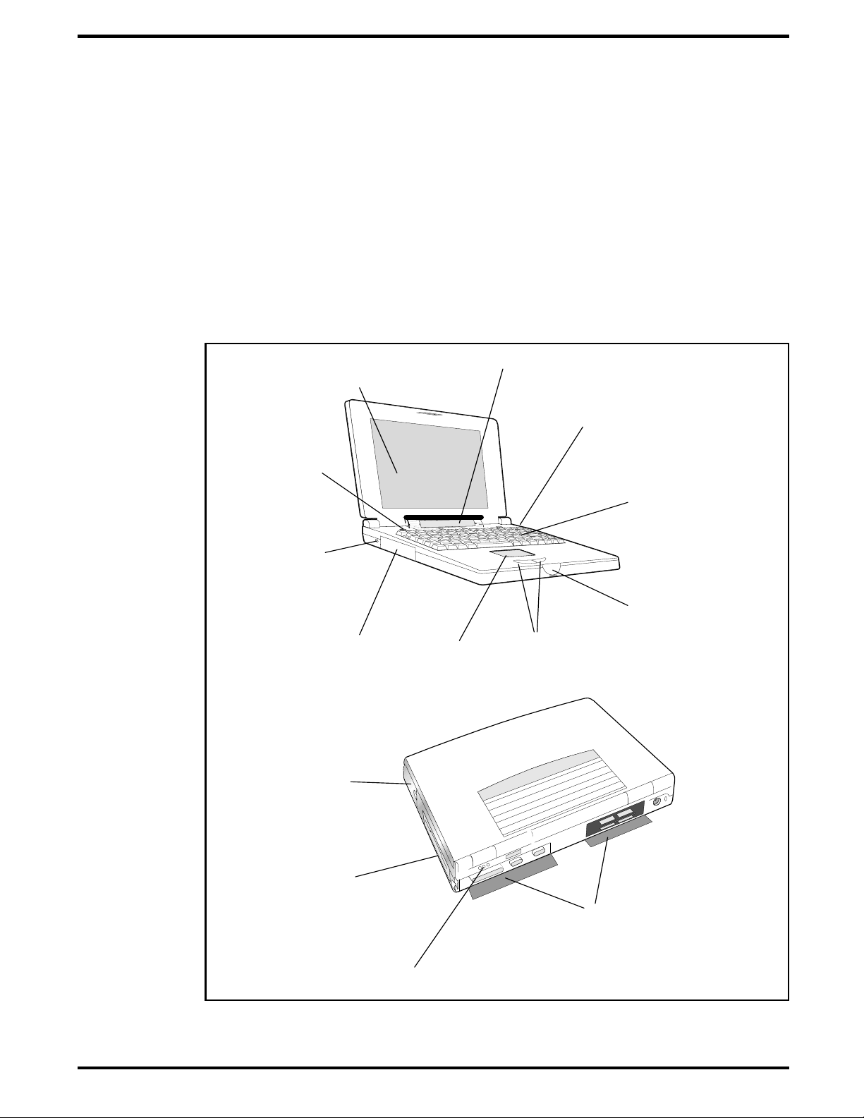
Page 13
Serial
Infrared
Port
Audio Line
In/Out/Mic In
Parallel
Port
Serial
Port
External
VGA Port
Connector for
External Expansion
System
PS/2 Port
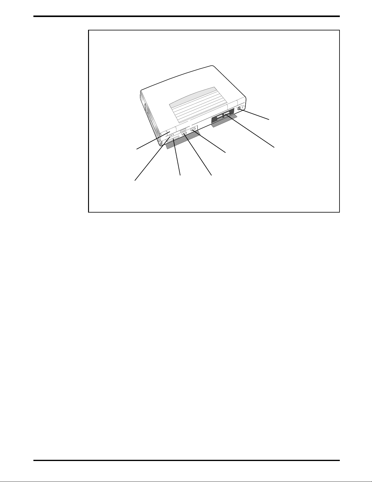
1.4.1
As shown in Figure 1-3, the notebook computer contains the following
external ports:
Serial Infrared (SIR) Port for wireless connection with a similarly
•
equipped printer or computer
9-Pin Serial Port for attaching any RS-232 type serial device to the
•
Notebook
15-Pin External VGA Monitor Port for attaching an external monitor
•
6-Pin PS/2 Port to attach an external Keyboard or Mouse
•
Audio In/Out and External Microphone Input
•
Expansion Bus Port for attaching an external expansion system
•
External Ports
Figure 1-3 Notebook External Ports
General Description
1-5
Page 14
Glidepad
Select Buttons
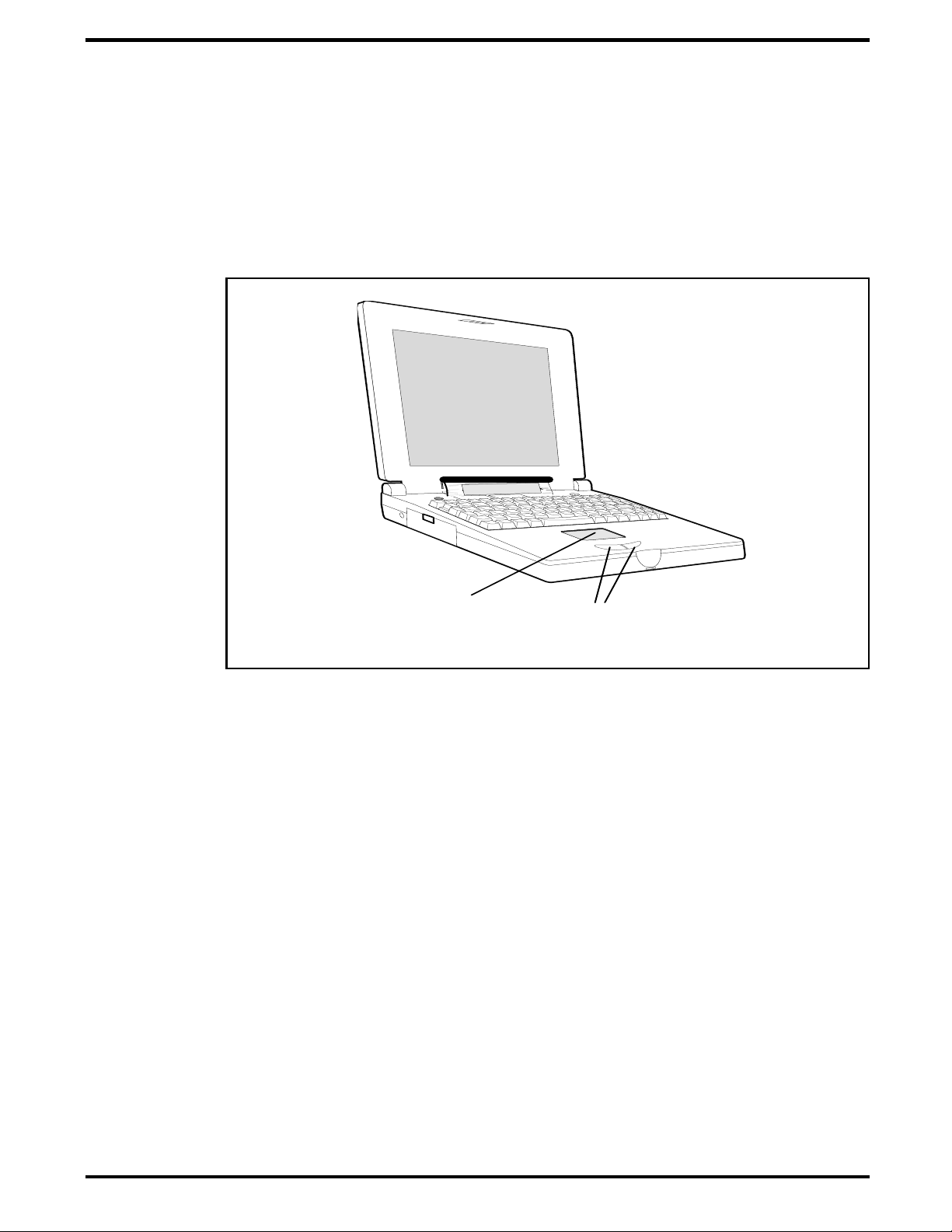
1.4.2
All members of the Extensa 57x family feature a built-in glidepad pointing
device located near the center of the keyboard’s palmrest. With light finger
pressure, the cursor can quickly be positioned to the desired point; a quick
double tap on the glidepad and you have selected an object. Two select
buttons (switches) are located along the front edge of the notebook for use in
the traditional select/drag features of a mouse device.
.
Glidepad Pointing Device
Figure 1-4 Extensa 57X Series Glidepad
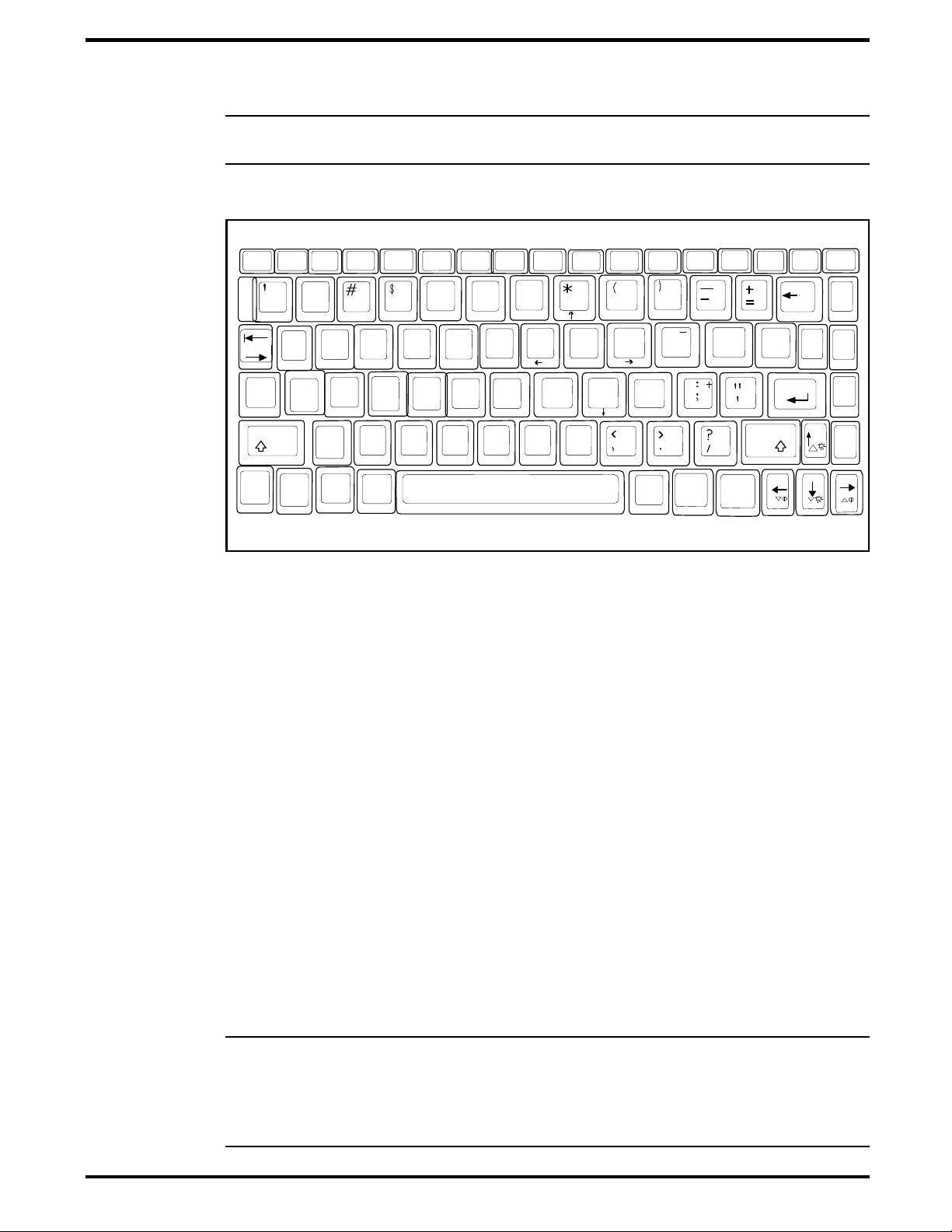
1.4.3
The Extensa 57x Series Keyboard is a full function keyboard with the
standard character and function keys plus 12 programmable function keys
(F1 through F12) .
Using the Sp ecial Functio n (Fn) key which assigns multiple functions to
keys, the keyboard can emulate IBM
The notebook ke yboard is available in two basic versions:
U.S. English - This version (also known as the domestic version) is
•
generally us ed in the United States and Ca nada.
U.K. English/Custom International Version - This version is adapted
•
(using appropriate keycap changes) for the international countries listed
in Table 1-2.
Keyboard
®
101/102 keyboards.
1-6
General Description
Page 15
n
Q
T Y
[
{
]
}
Caps
Lock
1
2
@
3
4
5
%
6
^
Shift
F5
F4
Enter
Esc
F1
F11
F10F9F8F7F6
Prt Sc
SysRq
NumLk
Pad
F2
F3
0
8
9
PgUp
7
&
Home
4
U
*9
F12
P
Home
Scroll
Lock
Backspace
Pause
Break
PgUp
|
\
PgDn
Ins
Alt
Del
Fn
AltCtrl
~
`
Tab
Shift
Z
End
X
C
V
B
N
M
Ins
Del
D
F
G
H
6
O
.
/
8
7
S
R
E
A
W
5
I
L
J
K
End
PgOn
1
23
Note:
The Extensa Series Notebook Computer User’s Reference Manual con-
tains descriptions o f keyboard special fu nction keys.
Figure 1-5 Extensa Keyboard
1.4.3.1 Controls and Indicators
The Extensa 57x contains a Power Button and a Status LCD just above the
keyboard. All notebook functions (except the power On/Off function) are
controlled by keyb oard keys in conjun ction with the
1.4.4
Standard Power Features
Notebook power for the Extensa 57x Series Notebook Computers is provided
by an AC Adapter and a rechargeable nickel metal hydride (NiMH) battery
pack that installs in a power bay near the front of the notebook (right side).
A second lithium ion battery may optionally be installed in the Floppy Drive
bay when the Floppy Drive is removed from the Notebook.
n
All members of the Extensa 57x family feature a power management
subsystem (hardware and software) that provides for longer portable
operation and protection of files during low battery conditions.
Note
ditioning in order to charge to full capacity. To accomplish this, remove the
AC Adapter a nd the seconda ry battery p a ck (if installed). Allow the notebook
to deep discharge. Then, recharge to full capacity. The secondary battery
pack is a Lithium-Ion type that does not require conditioning.
: The Nickel Metal Hydride (NiMH) battery requires periodic battery con-
Fn
key.
General Description
1-7
Page 16

n
1.4.5
The Extensa Series notebooks are equipped with a Serial Infrared (IR) port
that offers wireless communication with a variety of IRDA compliant
devices made by other manufacturers.
Note
: Prior to communicating with an external device equipped with a serial
infrared interface, the appropriate third-part y drivers must be inst all ed o n
your notebook.
1.4.6
All members of the Extensa 57x Notebook family are preloaded with the
Windows 95 Operating System. In addition, Extensa 575CD and 575 CDT
models come standard with the following application packages installed:
Microsoft Works
•
Quicken SE
•
Wireless Connection With Serial Infrared Port
Preloaded Software
Lotus Organizer
•
Microsoft Entertainment Pack No. 4
•
1.4.7
Expansion capabilities bu il t i nt o th e Ex tensa notebook serie s inc lude:
User installable expansion RAM memory (to a maximum of 40 MB)
•
By removing the floppy dr ive, you can ad d either a second battery pack
•
or CD-ROM Drive.
Cable Connect P S/2 Nu me ric Keypad option, TI Part N o . 2581381-0001,
•
or other PS/2 type device (e.g. keyboard or mouse) can be attached to
the PS/2 Port.
A parallel de vi ce can be attached to the noteb o ok’s external 25 -pin
•
parallel port (EPP/ECP compatible).
With one of the DockMate desktop expansion systems installed,
•
additional expansion ports are available
Notebook Expansion Capabilities
1-8
General Description
Page 17

1.5
The Extensa Series Notebook Computers use modular design and built-in
test features to reduce the mean time to repair. A power on self test
program automatically verifies the operational state of the primary circuits.
Also, the notebook contains a powerful suite of diagnostic tests called
PC-Doctor, (described in detail in Appendix B) that can perform additional
levels of di a gnostic testing.
1.6
Standard Test Features
Notebook Assemblies and
Subassemblies
The Extensa Series Notebooks are modular in design and can be
disassembled for maintenance purposes using a standard set of flat-bladed,
Phillips-head and hexagonal screwdrivers. The major assemblies that
comprise a typical notebook in the Extensa family are shown in Figure 1-6
and briefly described in the following paragraphs.
General Description
1-9
Page 18
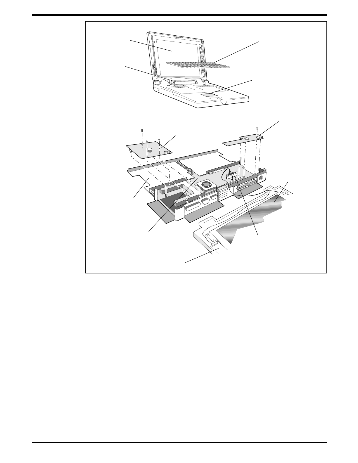
Display Assembly
Status LCD
Assembly
Keyboard Assembly
Glidepad Assembly
Power Supply Board
IR/Sound Board
Display Assembly
Floppy
Drive/CD-ROM
Bay
Main Board
Display Cable Interface
Board
Inverter Board
Figure 1-6 Notebook Assemblies
1.6.1
The Cover-Display Assembly contains the LCD screen and associated high
voltage power supply and video circuitr y. The Cover-Display Assembly
contains several field-re placeable com ponents inclu ding:
LCD Assembly
•
Cover-Display Assembly
1-10
Inverter Board
•
Bezel
•
Hinge Covers
•
Internal cables
•
General Description
Page 19

1.6.2
As shown in Figure 1-6, the majority of the notebook’s field replaceable
units (FRUs) are located in the system base assembly. These FRUs include:
Main Board Assembly
•
Hard Disk Drive Assembly
•
Up to two Dual Inline Memory Modules
•
LCD Status Assembly
•
Floppy Drive Module
•
IR/Sound Board Assembly
•
Power Supply Board Assembly
•
Battery Pack Assembl y
•
Top Case Assembly
•
System Base Assembly
Glidepad Assembly
•
Keyboard Assembly
•
CMOS Battery Assembly
•
HDD Connector Board Assembly
•
1.7
Extensa 57x Series Notebook
Specifications
Specifications for the Extensa 57x Series Notebooks are provided in Table
1-3.
General Description
1-11
Page 20

Table 1-3 Extensa 57x Notebook Features
Specifications Models 570CD/575CD
Processor
Memory
Standard:
Maximum:
Cache:
Display
LCD Type:
Simultaneous
LCD/Ext. SVGA
Video RAM Size:
Video Bus
:
Pentium 100 MHz Pentium 100 MHz
8 MB 8 MB
40 MB
256 KB L2 Cache
11.3 inch, SVGA, Dual
Scan Color
Yes Yes
1 MB 1 MB
PCI Bus with Gr a phics
Accelerator
Models
570CDT/575CDT
40 MB
256 KB L2 Cache
10.4 inch, SVGA, Dual
Scan Color/ Active
Matrix Color
PCI Bus with Gr a phics
Accelerator
Keyboard/Pointing
Device
Ergonomic Keyboard
Built-In Glidepad
Storage
Floppy Drive
Module:
Hard Drive
CD-ROM Drive
Interfaces
Serial (RS-232 ) Port
Parallel Port
(EPP/ECP)
External VGA Port
: 810 Million Bytes 1200 Million Bytes
Yes Yes
Yes Yes
3.5 inch, 1.44 MB 3.5 inch, 1.44 MB
4X or 6X Speed 4X or 6X Speed
Yes Yes
Yes Yes
Yes Yes
External PS/2 Port
Serial Infrared Port
Expansion Bus
1-12
General Description
Yes Yes
Yes Yes
PCI, supports Port
Replicator option
PCI, supports Port
Replicator option
Page 21

Specifications Models 570CD/575CD
Battery Pack
Sound Features
PCMCIA Supp ort
Windows 95
Windows for
Workgroups
Physical
Characteristics
Nickel-Metal Hydride,
optional Lithium-Ion
secondary battery pack
option
16-bit Stereo Sound, Audio
in/out and Microphone In
jacks, built in stereo
speakers and microphone
Type I/II, or III (Optional) Type I/II, or III (Optional)
Yes Yes
Yes (Model 570CD only) Yes (Model 570CDT only)
Models
570CDT/575CDT
Nickel-Metal Hydride,
optional Lithium-Ion
secondary battery pack
option
16-bit Stereo Sound,
Audio in/out and
Microphone In jacks,
built in stereo speakers
and microphone
Weight
Dimensions
NOTE
*
installed in the no tebook at any given time.
NOTE
Adapter or second battery option.
: Approx. 6.2 Pounds* Approx. 6.2 Pounds*
: 11.7” (L) X 1.7” (H) X 8.2”
(W)
: Only one module (Floppy Drive, CD-ROM or second Battery) may be
: Weight specifications do not include Floppy Drive, CD-ROM drive, AC
1.8
All Extensa 57x Series products meet the following standards:
Underwriter’s Lab (UL) Standard 1950 (safety)
•
Canadian Standards Association (CSA) Standard 220 (safety)
•
Agency Approvals
11.7” (L) X 1.7” (H) X 8.2”
(W)
FCC CFR 47, Part 15, Subpart J, FCC Level B (EMI)
•
Canadian Department of Communications (DOC) Certification
•
VDE 0871, Class B (EMI)
•
CE Mark
•
General Description
1-13
Page 22

2
Installation
n
2.1
This section contains u npacking and preparation for use instructions for
the Extensa 57x Series Notebook Computers.
2.2
Unpack the computer using the following instructions:
1.
Carefully cut the tape that seals the top flap of the shipping carton.
2.
Remove the computer and the accessories from the main shipping
3.
Remove all protective coverings from the computer .
4.
Remove the ho lding tape and open up the accessory bo x; remove the
Note:
Introduction
Unpacking Instructions
carton.
contents.
Save the shipping containers and packaging for later reuse.
n
c
2.3
If you have no options to install at this time, skip to Paragraph 2.4.
Otherwise, continue with Paragraph 2.3.1.
2.3.1
Note:
paragraph.
Caution: The Dual Inline Memory Module contains components that
are sensitive to static electricity. When handling the module and the internal parts of the computer, protect against static electricity by using
wrist or ankle grounding straps and grounded working mats. When moving or storing items, use the anti-static bags supplied with the items.
Installing Notebook Options
Installing Expansion Memory Modules
If not installing RAM Expansion option at this time, skip to the next
Installation
2-1
Page 23

1. Ensure that the notebook is powered off and that the AC Adapter and
internal battery pack(s) is (are) removed fro m the notebook.
2. Remove the Expansion RAM Module (Dual Inline Memory Module or
DIMM) from its shipping container.
3. Turn the Notebook over and locate the RAM Access Door (held in
place by two screws).
4
. Remove the two Phillips-head screws that hold the RAM access door
and remove the door.
5. Insert the edge of the first DIMM Board into the rear of either available
connector . Use a rocking motion and insert the board at an angle to
the surface of the Main Board. Fully insert the module. Push
downwards on each side of the DIMM module until it snaps in place.
Repeat the procedure for the second module.
6. Replace the RAM A ccess Door and all component s r em o ved in Step 1.
This completes the expansion memory module installation procedure.
2.3.2
The Notebook has provisions for two Type I or II options or one Type III
PCMCIA option card.
1. Review the installation instructions supplied with the PCMCIA option
card(s).
2. Open the PCMCIA compartment cover on the right side of the
notebook.
3. To insert a PCMCIA card, align the card with the socket and slide the
card into the socket until it locks into place.
4. To eject a PCMCIA card, first ensure that the notebook is not
accessing the memory card or device. Under Windows 95, go to the
Control Panel, PC Card selection and direct the card to stop before
removing card.
2.3.3
An optional numeric keyboard can be attached to the notebook via the
notebook’s PS/2 connector (refer to Figure 2-2).
Installing PCMCIA Options
Installing the Optional Numeric Keypad
2-2
Installation
2.4
The Extensa Notebook is shipped with a single b attery pack that is inserte d
from the front left side of the computer. A second battery pack (option) can
Installing the Battery Pack(s)
Page 24

be installed in the remo vable Floppy/CD- RO M bay. Two switches that used
to remove devices from the option bay are physically located on the bottom
of the Notebook. The left-most switch controls removal of the Primary
Battery Pack and the right-most switch controls removal of the d evice
installed in the Floppy/CD-ROM/Secondary Battery bay.
To remove or replace the batt ery pac k, fo l low the steps below.
1. Save an y data, then Power off the notebook. Disconnect the AC
adapter if installed.
2. Turn the notebook over an d press the battery release switch while
pressing outwards on the primary batt ery pack. Remove the battery
from the Notebook.
3. Insert a new or recharged battery pack into th e battery compartment
bay. Make sure that the contacts are facing up and to the rear of the
compartment.
c
Caution: There is danger of explosion if the battery is incorrectly replaced. Replace the battery only with the same or an equivalent type
recommended by the manufacturer. Discard used batteries according to
the manufacturer’s instructions.
4.
2.5
Most external devices connect to the Notebook via the connectors on the
rear of the notebook as s ho w n i n F igu re 2- 1. A dditional connectivity can be
obtained by installing an optional Port Expander to the Notebook’s PCI
Expansion Bus.
If installing a secondary bat t ery pack, insert the battery pack into the
front right side of the n o te bo o k until the battery pack clicks in place.
Installing External Devices
Installation
2-3
Page 25
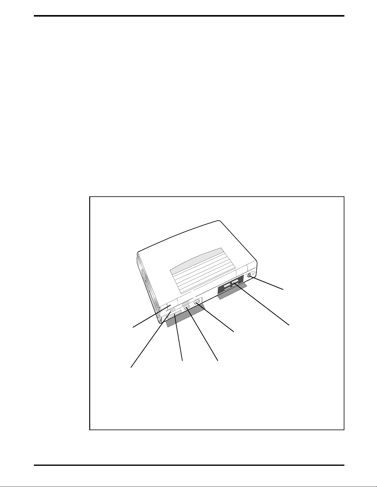
PS/2 Port
Serial
Infrared
Port
Audio Line
In/Out/Mic In
Figure 2-1 I/O Connector Locations
2.5.1
As shown in Figure 2-2, the notebook has one external PS/2 port on the
rear of the Notebook for installing a PS/2 compatible device (keyboard,
mouse, etc.). Additional PS/2 devices may be installed using the Port
Expander option. Pinouts for the PS/2 port on the rear of the Notebook are
also provided in Figure 2-2.
Installing an External Keyboard/Mouse
Parallel
Port
External
VGA Port
Serial
Port
Connector for
External Expansion
System
2-4
Installation
Page 26
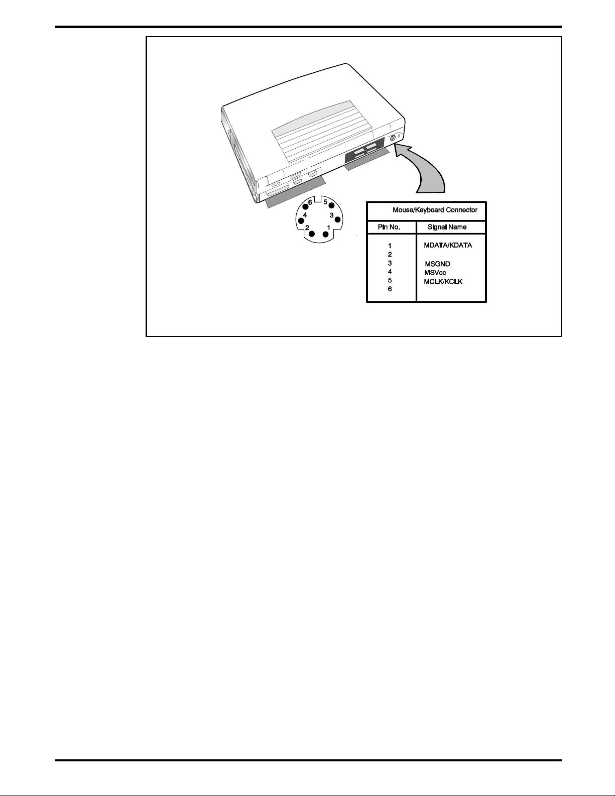
Figure 2-2 PS/2 Port Assignments/Pinouts
To install an external keyboard or external PS/2 mouse on the notebook,
use the following procedure:
1. Ensure that the notebook is powered off.
2. Locate the external PS/2 port at the rear of the notebook (refer to
Figure 2-2).
3. Attach the PS/2 cable from your mouse and/or keyboard cable to the
PS/2 port.
4. Power on any other peripheral devices you may have connected to the
notebook, and then po wer up the notebook .
Installation
2-5
Page 27

1
2
3
4
5
6
7
8
9
10
11
12
13
14
15
16
17
18
19
20
21
22
23
24
25
STROBE
DATA BIT 0
DATA BIT 1
DATA BIT 2
DATA BIT 3
DATA BIT 4
DATA BIT 5
DATA BIT 6
DATA BIT 7
ACKNOWLEDGE *
BUSY
PAPER OUT
SELECT
AUTO LINEFEED *
ERROR *
INITIALIZE PRINTER *
SELECT IN *
GROUND
GROUND
GROUND
GROUND
GROUND
GROUND
GROUND
GROUND
PIN
SIGNAL
PARALLEL PO RT PI NOUT S
NOTE:
* ACTIVE LOW
1
2
3
4
5
6
7
8
9
10
11
12
13
14
15
16
17
18
19
20
21
22
2324
25
2.5.2
Installing External Parallel Printer
The Notebook is equipped with a bidirectional, ECC/EPP compatible, 25-pin
parallel printer port. The connector pinouts and connector location are
shown in Figure 2-3.
Figure 2-3 Parallel Port Location/Pinouts
2-6
Installation
Page 28

1
2
3
4
5
6
7
8
9
SERIAL PO RT PINO UTS
1
2
3
4
5
6
7
8
9
DCD (CARRIER DETECT)
RXD (RECEIVE DATA)
TXD TRANSM IT DA TA)
DTR (DATA TERMINAL READY)
GND (GROUND)
DSR (DATA SET READY)
RTS (REQUEST TO SEND)
CTS (CLEAR T O S EN D)
RI (RING INDICATOR)
PIN
SIGNAL
c
2.5.3
Installing External Serial Port Device
The notebook contains an RS-232 serial port with a male DB-9 connector as
shown in Figure 2-4. The serial ports are used to interconnect such devices
as:
External Modem
•
Serial Printer
•
Any device that uses an RS-232 interface
•
To connect a printer to the notebook, ensure that both the notebook and the
printer are turned off.
Caution: Never connect a parallel device to a serial port or a serial device to a parallel port or video port; this may cause damage to the Notebook and/or peripheral device. If you are uncertain of what type
connector the external device has, refer to the technical manual for
the external device.
Figure 2-4 Serial Port Location/Pinouts
Installation
2-7
Page 29

1
2
3
4
5
6
7
8
9
10
11, 12
13
14
15
RED VIDEO
GREEN VIDEO
BLUE VIDEO
NOT USED
GROUND
RED RETURN
GREEN RETURN
BLUE RETURN
NOT USED
GROUND
NOT USED
HORIZONTAL SYNC
VERTICAL SYNC
NOT USED
OUTPUT
OUTPUT
OUTPUT
INPUT
INPUT
INPUT
OUTPUT
OUTPUT
PIN
SIGNAL NAME
DIRECTION
EXTE RNA L VGA CONNECTOR PINOUTS
1
2
3
4
5
7
8
9
10
6
1112
13
14
15
2.5.4
Installing External SVGA Monitor
The notebook is capable of driving both its internal LCD disp lay and an
external SVGA monitor (LCD only, simultaneous, or SVGA only). The
external monitor connector pinouts and connector locat ions are shown i n
Figure 2-5. To install an external monitor with the notebook, use the
following steps:
1. Ensure that both the notebook and the external monitor are turned
off.
2. Locate the 15-pin female SVGA port on the Port Adapter.
3. Attach the appropriate end of the monitor cable to the SVGA port on
your notebook. If the monitor cable connectors have retaining screws,
tighten them down.
4. If necessary, connect the monitor power cable to the monitor, and
plug the monitor power cable into an electrical outlet.
5. Power on the monitor, as well as any other peripheral devices
connected to th e notebook; then po wer up the noteboo k.
2-8
Installation
Figure 2-5 Connecting an External SVGA Monitor
Page 30

Serial
Infrared
Port
2.5.5
The Serial Infrared (IR) port offers wireless communication with a variety of
IRDA-compliant devices made by other manufacturers. Ensure that the
third-party manufacturer supplies you with the appro pri ate IR drivers
before attempting connection. As shown in Figure 2-6, the Notebook SIR
port is located just above the serial port connector on the rear of the
notebook. Align this port with the SIR port on a printer, notebook or other
device equipped with an SIR port.
Installing SIR Devices
Figure 2-6 Communicating with SIR-Equipped Devices
Installation
2-9
Page 31

c
2.6
Use the following procedures to connect the AC Adapter to the system:
Caution: Use only the AC Adapter supplied with the computer; other
adapters can damage the unit.
1.
Remove the AC adapte r from the packaging. Connect the round coaxial
2. Connect the female side of the AC Power cord to the AC Adapter and
Installing the AC Power Adapter
connector on the AC Adapter to the power receptacle on the left side
(rear corner) of the notebook as s hown in Figure 2-7.
connect the male end to a grounded AC outlet.
AC Power
(120VAC to 230 VAC,
50 to 60 Hz)
AC Adapter
Figure 2-7 AC Adapter Installation
2.7
After you’ve installed all internal options and external cabling, you’re ready
for system checkout and software configuration.
Initial System Checkout
2-10
To check out the system, se t the power switch on the notebook to the On
position which initiates the notebook self test. During self test execution,
the computer checks the operation of all critical hardware including
memory and CPU (and displays copyright and version number data during
test execut io n).
Installation
Page 32

Upon succes sf ul conclusio n o f self test, the computer a u tomatically loads its
operating sy stem and Wi ndows environ m ent. If self test fails to com plete
and an error message is displayed, try powering down the computer for a
couple of minutes and turning power back on to repeat self test. If the error
message persists, see Section 5 for troubleshooting information (also refer to
Appendix A for self test error message descriptions).
2.8
The first time you power up the notebook, it automatically runs the Setup
Program which prompts you for country name and printer type. You exit
Windows and the notebook begins unzipping files and preparing the
software for use. After initial installation, and the timeout occurs, the demo
may begin. To stop the demo, move the cursor to the center of the screen
and click the left mouse button. A number of demo options are then
available.
2.9
The Notebook is preloaded with W indows 95 operati ng sy stem software.
Prior to exte nded use of the n o tebook, create a backup set of system
software using the Backup Utility under Windows 95. In the event of a disk
problem, you can restore your system using the Restore Utility and the set
of backup disket tes you’ve just cre a ted.
Configuring the System
Making Backups of System Software
2.10
For assistance in loading Application Software, refer to Chapter 5 in the
Extensa Series Notebook Computer User’s Reference Manual.
Loading Application Software
Installation
2-11
Page 33

3
Power
Button
Status LCD Display
Glidepad
(Mouse)
Mouse S elect
Buttons
Operating Instructions
n
3.1
This section describes the Ex tensa 57x Ser i es Notebook operating c o ntrols
and indicators.
Note:
Notebook Computer Users Guide.
3.2
The Extensa Ser ies Noteboo ks are equipped with the follo wing control s a nd
indicators:
Alternate action Power Button in the upper left corner above the
•
keyboard
Status LCD ce ntered above th e keyboard - ICONs are used to convey
•
status information (refer to Figure 3-1)
Embedded special function keys in the keyboard (including Contrast
•
and Brightness Control) are activated by the Fn key
Introduction
For additional operating instructions, refer to the Extensa 57x Series
Notebook Controls and Indicators
Figure 3-1 Extensa Series Controls and Indicators
Operating Instructions
3-1
Page 34

3.2.1
The TFT version of the notebook contains no operating controls or
indicators. Use the function keys to adjust the contrast and brightness. TFT
versions are unaffected by contrast "key" adjustments.
3.2.2
The notebook contains one button switch above the keyboard: the
On/Off
power to the unit. Pressi ng the Power button cau s es power to be applied to
the notebook, power u p self test to be run and Windows 95 to be loaded.
When the Power button is pressed again, the Notebook powers down and all
data in RAM memory is lost.
3.2.3
The Notebook con tai ns a Cover Release latch near th e center of the top
cover. To open the notebook, lift up on the release mechanism along the
front edge of the notebook.
3.2.4
LCD Contrast Control
Button Switches
Power
Switch. This button is an alternate action type switch that controls
Cover Release Latch
Glidepad Controls
The Extensa 57x Series Notebo o k Computers are eq u ipped with a bui lt-in
mouse device called the glidepad physically located at the base of the
keyboard (refer to Figu re 3- 1).
The cursor is positioned by touching and dragging your finger in the
direction you want the cursor to go. The select functions are performed
either by tapping the glidepad or by pressing the two buttons (switches) at
the bottom of the keyboard.
You can chan ge the operation of the pad by changing val ues in the mouse
section of the Windows 95 Control Panel. Once your cursor is in the proper
place and you want to select, use the left button to click or double-click just
as you would with a mouse.
3.3
Some of the operating features useful for notebook maintenance are
provided in the following paragraphs. For additional operating instructions,
refer to the Extensa 57X Series Notebook Computer User’s Manual.
3.3.1
Operating Procedures
Floppy Drive Operating Procedures
3-2
Operating Instructions
To avoid damaging the floppy drive, and to protect data, take the following
precautions:
Never turn off or reset the notebook while the floppy activity indicator is
•
lit.
Keep the AC adapter at least 6 inches away from your drive.
•
Page 35

Insert the floppy into the floppy drive slot with the label side up and the
•
metal-shutter end first. Gently push the floppy into the floppy drive slot
until the floppy clicks into place.
To remove a floppy diskette, press the eject button until the floppy pops
•
out.
Never force open the access shutter on a floppy.
•
Always remove a floppy from the floppy drive before turning off the
•
computer.
Never transport the computer with a floppy in the floppy drive. Doing so
•
can damage the drive head.
If a floppy appears to be damaged, try to make a copy of it, and
•
immediately discard it.
Keep all floppi es when not in use in a disk storage box to protect them
•
from damage or loss.
Operating Instructions
3-3
Page 36

3.3.2
PCMCIA cards are inserted and ejected in much the same way as diskettes:
Up to two Type I or Type II PCMCIA options may be installed i n the
•
compartment on the right side of the notebook. One Type III Option may
be installed in the lower slot.
To insert a PCMCIA card, align the card with the socket and slide the
•
card into the socket until it locks into place. To install a Type III option,
you must remove the Floppy Drive.
To eject a PCMCIA card, go to the Windows 95 Control Panel, select
•
Card
remove the PCMCIA option.
3.3.3
Refer to the User’s Guide shipped with the notebook for a description of
•
the recognized hot keys.
Installing/Removing PCMCIA Options
PC
and select th e card to stop ; then press the release button and
Computer Hot Keys
3.3.4
The computer generally will notify you when you are reaching a low battery
condition by performing the following actions:
One beep every 10 seconds (unless battery warning is disabled)
•
The battery low w a rni ng is automatically disabled when the AC A dapter
•
is installed on the notebook regardless of the charge condition of the
battery pack.
If the AC adapter is not plugged in within three minutes of a detected
•
battery low cond ition, the notebook enters Standby mo de.
The Notebook returns to the normal operating mode when the power
•
switch is activated. Unit then recovers RAM information from the hard
drive and restores unit to previous "On" condition.
3.3.5
The following actions can minimize power usage and protect your work
during the critical minutes before you shut the system down or replace one
of the battery packs wi th a fully charged pack:
Responding to Low Battery Conditions
Minimizing Power Usage
3-4
Operating Instructions
Press
•
Save RAM Disk (if using RAM Disk feature)
•
Power down the system if you do not ne ed the comput er
•
Ctrl-Standby
to shut off the alarm (if it’s enabled)
Page 37

3.3.6
A standalone battery charger option is available to charge notebook battery
packs. The battery pac ks may al so be charged in the noteboo k as follows:
1. Install the battery pack(s) in your computer (if not already installed).
2. Connect the AC Adapter as described in Section 2.
3. To fully charge the battery pack, leave it charging in the Notebook for
at least another 90 minutes.
4
. Periodically recondition the primary battery (Nickel Metal Hydride) as
described in Paragraph 3.3.7.
3.3.7
The primary ba ttery pack is a Nickel-Me t a l Hydride type that requir es
periodic deep discharge and recharge in order to accept a full charge
(approximately every 5 or 6 charge/recharge cycles). To condition the main
battery, use the following procedure:
1. Remove the s econdary battery (if installed in the Floppy Drive ba y)
and AC Adapter (if installed).
Recharging the Battery Packs
Conditioning the Primary Battery
2. Power up the computer and leave it on until the primary battery is
completely discharged; then reconnect the AC adapter and fully
charge the battery. Reinstall the second ary battery in the Flop py Bay
(if using a secondary battery pack).
3.3.8
When you power up the Notebook, it automatically checks for certain key
files that must be present for normal system operation. If any of these files
are accidentally erased, as indicated by error message, insert the
Windows95 Startup diskette and reboot the system. This will allow you to
boot up and troubleshoot your system.
3.3.9
In the event of a hard drive replacement or system board replacement which
resulted in loss of system software, you may need to rebuild the entire
system soft ware structure.
The following items are required to rebuild the system software:
Set of backup diskettes of the system soft w a re
•
Restoring Missing System Files
Rebuilding the System Software
Operation al Notebook
•
Insert the Windows 95 Startup diskette in the Notebook’s floppy drive and
power up the system.
Operating Instructions
3-5
Page 38

n
Note
: For additional operating procedures, refer to to the Extensa 500 Series
Notebook Computer User’s Manual
9803942-0001.
,
Texas Instruments Part No.
3-6
Operating Instructions
Page 39

4
Theory of Operation
4.1
This section describes the noteboo k theory of operation.
4.2
Functionally, the notebook computer consists of the following major
subsystems:
Processor and Memory Subsystem
•
I/O Subsystem
•
Video Subsystem
•
Hard Disk Subsyste m
•
Floppy Disk Subs ystem
•
CD-ROM Subs ystem
•
PCMCIA Subsystem
•
Introduction
Notebook Functional Description
Sound Subsystem
•
Serial Infrared Subsystem
•
Power Subsystem
•
A functional block diagram of the Extensa 57x Series Notebook is shown in
Figure 4-1.
4.2.1
The Processor function, housed on the Main Board, is implemented with the
Intel Pentium Proce ssor (P54C/LM). The processor operates in
conjunction with RAM and ROM Memory on the Memory Board and other
control logi c o n the Main Board to process software instructions ( BIOS,
Windows 95, and Applications).
Primary control for the Processor/Memory subsystem is implemented with
the Pentium Chipset ( O pti Viper 82C556/82C557).
The memory subsystem, implemented on the Memory Board and optional
Dual Inline Memory Modules, provides 8 MB (expandable to 40 MB) of fast
Processor/Memory Subsystems
Theory of Operation
4-1
Page 40

DRAM memory, 128 bytes of CMOS RAM (battery backed up) and 256 KB of
Flash ROM for sy stem and video B I OS storage.
The basic 8 MB memory system can be expanded to a maximum of 40 MB
by the addition of two DIMM memory modules (refer to Section 6 for
installation details).
Tables 4-1 through 4-3 cont ain the Notebook I/O add ress map, D M A
channel assignments and IRQ interrupt level assignments respectively.
PCMCIA Option Slot(s )
PCMCIA Adapter
UM8365A
Pentium
Proces sor
(P54C/LM)
Cache MEMORY
CPU Data
Memory
Data
MAIN BOARD
DBC
82C556
SYSTEM &
SVGA BIOS
Drivers/
Receivers
PCI Bu s
Expansion Bus
Connector
RS232
SERIAL POR T
HDD
CD-ROM
CPU Address
System
Controller
82C557
RTC
82C602A
Interna l
Glidepad
PCI B us
PMU/Keyboard
Controller
DRAM
(2 Bank)
SIMM Memory
Expansion
Modules
EXTERNAL
SVGA MONI TOR
IPC
PCI Bus
1 MB
Video RAM
Video
Controller
Super I/O
Controller
IR/Audio
IR/Sound
Board
Board
INTERNAL 1.44 MB
FLOPPY DISK DR IV E
PARALLEL
PRINTER PORT
SIR
Interface
Audio IN/ OUT
Mic In
Input From
AC Adapter
Batte ry Packs
4-2
Theory of Operation
INTERNAL KEYBOARD
INTERNAL LC D DIS PL AY
640 X 480
SVGA LCD
Figure 4-1 Notebook Functional Block Diagram
Page 41

Table 4-1 Extensa Series I/O Address Map
Address Range Device
000-00F DMA Controller 1
020-021 Interrupt Controller 1
022-023 M1429 Registers
040-043 Timer 1
060-06E Keyboard Controller 8742 Chip Select
070-071 Real Time Clock and NMI Mask
080-08F DMA Page Register
0A0-0A1 Interrupt Controller 2
0C0-0DF DMA Controller 2
1F0-1F7 Hard Disk Select
178, 17A 6377 Registers
1F0-1F7 Hard Disk Select
3F6, 3F7
278-27F Parallel Port 3
35F, 36 F Special I/O Ports
378, 37A Parallel Port 2
3BC-3BE Parallel Port 1
3C0-3C5
3C6-3C9 Video DAC
3C0-3CF Enhanced Graphics Display
3D0-3DF Color Graphics Adapter
3E0-3E1 PCMCIA Controller
3F0-3F7 Floppy Disk Controller
3F8-3FF Serial Port 1
Theory of Operation
4-3
Page 42

Table 4-2 DMA Channels
Controller Channel Address Function
1 0 0087 Spare
1 1 0083 Spare
1 2 0081 Diskette
1 3 0082 Spare
2 4 Cascade Cascade
2 5 008B Spare
2 6 0089 Spare
2 7 008A Spare
Table 4-3 IRQ Interrupt Levels
Priority Interrupt
Interrupt Source
Number
1 SMI Power management unit
2 NMI Parity Error Detected, I/O Channel Error
3 IRQ0 Interval Timer, Counter 0 Output
4 IRQ1 Keyboard
IRQ 2 Interrupt from controller 2 (cascade)
5 IRQ8 Real Time Clock
6 IRQ 9 Cascaded to INT 0AH (IRQ 2)
7 IRQ10 Reserved
8 IRQ 11 Reserved
9 IRQ 12 PS/2 Mouse
10 IRQ13 INT from Coprocessor
11 IRQ14 Hard Disk Controller
12 IRQ15 Reserved
13 IRQ3 Serial Comm Port 2
14 IRQ4 Serial Comm Port 1
15 IRQ5 Reserved
16 IRQ6 Diskette Controller
4-4
Theory of Operation
Page 43

n
Priority Interrupt
Number
17 IRQ7 Parallel Port
Note:
A PCMCIA card can use IRQ 3, 4, 5, 7, 9 and 11 as long as it does not
conflict with the interrup t a ddress of any o ther device.
4.2.2
The I/O subsystem, imple m en ted with an SMC37C655 IR Su per I/O
Controller Chip, provides for such functions as internal floppy drive control,
serial and parallel ports and support for the Serial Infrared port. The Super
I/O Controller includes the following features:
100 percent compatible with ISA, EISA, and micro-channel architectures
•
Built-in floppy disk controller
•
I/O Subsystem
Interrupt Source
Two UARTs
•
•
Software compatible wi th the PC16550A and PC16450
•
MIDI compatible
•
Infrared support on UART2 (IRDA-compliant)
Bidirectional Parallel Port
•
•
Enhanced Parallel Port (EPP) compatible
•
Extended Capabilities Port (ECP) compatible, including level 2
support
•
Bidirectional under either software or hardware control
•
Compatbile with ISA, EISA, and Micro Channel architectures
•
Ability to multiplex FDC signals on parallel port pins for
external FDD
•
Includes protection circuit against damage caused when
printer is powered up, or operated at higher voltages
Integral address decoder- provides selection of all primary and
•
secondary ISA addresses including COM1-4 and LPT1-3.
Enhanced P ower Management Funct ion
•
•
Enhanced programmable power-down and wake-up modes
Theory of Operation
4-5
Page 44

• Auto power-down and wake-up modes
• Typical current consumpt io n du ri ng power-down is less than
10A
4.2.3
The video subsystem, implemented on the Mai n B o ard and on the LCD
Display Unit, displays text, graphics and drives an external SVGA port. The
video subsystem is implemented with a Cirrus Logic CL-GD 7543 high
performance VGA controller and supporting logic and video RAM (1 MB).
The major features of the VGA controller include:
Highly integrated design (flat panel / CRT VGA controller, RAMDAC,
•
clock synthe sizer)
Multiple Bus Architecture Integrated Interface
•
Integrated programmable linear address feature accelerates GUI
•
performance
Supports panel resolutions up to 1280 X 1024 resolution including 800
•
X 600 and 1024 X 768
Video Subsystem
• Local Bus (32-bit CPU D irect and VL)
• EISA/ISA (PC/AT) 16-bit Bus
SMARTMAP intelligent co lo r to gray sca le conversion enhances text
•
legibility
Text enhancement feature improves white text contrast on flat panel
•
displays
Fully Com p a tible with I BM SVGA
•
4.2.3.1 External SVGA Drive Capability
The Extensa 57Xcontains an external SVGA port (15-pin, female, D-type
connector) which can be used to drive an external CRT (standard SVGA
modes with resolutions of 800 X 600 X 256, or 64 0 X 480 X 256).
4.2.4
The Hard Disk Subsystem, controlled by the IDE interface compatible
82C558N IPC chi p, provides disk storage for a ll system software and user
files. Initially, the 57X Series Notebooks are equipped with a removable 810
or 1200 Million Byte hard drive.
During the manufacturing process, Texas Instruments formats the hard
disk and then loads all supplied softwa r e including Windows 95.
Hard Disk Subsystem
4-6
Theory of Operation
Page 45

c
Caution: Formatting the disk drive erases any data that may be stored
on the disk. Therefore do not attempt a format of the hard disk unless
the computer self test and diagnostics confirm that the disk has not
been formatted.
A Hard Drive activity ICO N is located on the S tat u s LED beneath the
Display Assembly. This ICON is visible during hard driver read/write
accesses.
c
Caution: The notebook should not be moved when the HDD ICON is lit
to prevent accidental damage to the hard drive.
4.2.5
The Floppy Diskette Drive Subsystem consists of a Floppy Controller (part of
the Super I/O Chip, SMC37C655IR) and the removable Floppy Diskette
Drive. The Floppy Diskette Drive can read/write standard 3.5-inch
minidiskettes. The floppy drive installs in the Media Bay and can be
removed to install a CD-ROM drive or a second battery pack (Lithium Ion).
4.2.6
Many of the Extensa 57x models are equipped with a removable 5.25 inch,
CD-ROM drive (4X or 6X speeds). The drive us es the standard ATAPI
interface.
The CD-ROM su bsystem is contr o lled by the IPC (which also control s the
hard drive subsystem).
Floppy Diskette Drive Subsystem
CD-ROM Subsystem
4.2.7
The notebook is equipped with an on-bo ard PCMCIA host adapter
(UM8366F) PCMCIA Controller) and sockets to support Type I, II, or III
options. The PCMCIA Controller has the following features:
Single-chip PCMCIA host adapters
•
Direct connection to ISA (PC AT) Bus
•
Direct connectio n t o PCMCIA 2.0 Bus
•
PCMCIA 2.0- and JEIDA 4.1-compliant
•
82365SL-compatible register set, ExCA-compatible
•
Automatic Low-power Dynamic Mode for lowest power consumption
•
Programmable Suspend Mode
•
Five programmable memory windows per socket
•
PCMCIA Subsystem
Theory of Operation
4-7
Page 46

Two I/O windows per socket
•
Programmable card access cycle timing
•
8- or 16-bit CPU interface
•
8- or 16-bit PCMCIA interface support
•
ATA disk interface support
•
Automatic flash memory timing support
•
Easy host interface using ISA I/O addresses 03E0h, 03E1h
•
Mixed-voltage (3.3V or 5V) operation
•
Dual-socket-interface, 208-pin QFP
•
4.2.8
Some models of the Extensa 57x Series notebooks are equipped with a
16-bit stereo sound system including:
Built-in microphone and stereo spea kers
•
Stereo line input (5-pin jack, DIP)
•
Stereo Line Output (5-pin jack, DIP)
•
External microphone input (5-pin jack, DIP)
•
Audio chipset
•
The sound subsystem is physically implemented on the IR/Sound Board.
4.2.9
The Power Subsystem consists of the following major parts:
Power Management (hardware and software components)
•
Sound Subsystem (Model Dependent)
Power Subsystem
4-8
Theory of Operation
AC Adapter
•
Power Supply Board
•
Nickel Metal Hydride (NiMH) Battery Pack
•
Optional Secondary Battery Pack (Lithium Ion) if not using the Media
•
Bay for a floppy drive or CD-ROM Drive
4.2.9.1 Power Management
The notebook is equipped with a power management function that
minimizes battery usage fo r pro lon ged battery operation an d au tomatically
recharges the batteries when the notebook is used with an AC adapter.
Page 47

The power management modes and warnings include the following:
LCD standby mode
•
Hard disk/CD-ROM standby mode
•
System standby/suspend mode
•
Battery-low warning
•
Standby/suspen d u pon battery low
•
4.2.9.2 AC Adapter
The notebook uses an AC adapter with built in over voltage and short circuit
protection.
The adapter can with stand a continuous short-circuit to DC output without
damage to the notebook logic components and resets to the normal power
mode after the fault condition is removed.
4.2.9.3 Primary Battery Pack
The Extensa 57x Series Notebooks use a Nickel Metal Hydride battery as the
primary battery pack. Speci f ic ati o ns for the primary battery pack are
provided in Table 4-4.
Table 4-4 Primary Battery Pack Specifications
Function Specifications
Battery type NiMH (Nickel Metal-Hydride)
Cell Type A
Nominal voltage 8.4 V
Cell energy capacity 4200 mAH
Nominal rated
capacity
Charge and discharge
cycles
27 W att-hours
500 (minimum)
Theory of Operation
4-9
Page 48

4.2.9.4 DC-DC Converter/Battery Charger Circuit
The power supply board in cludes two DC -DC Converter circuits an d a
battery charging circuit that operate the notebook and charge the internal
batteries when the AC Adapter is attached to the notebook. The converters
operate from an input voltage between 7 VDC and 20 VDC (from the AC
adapter) and generate the regulated voltages required to power all internal
logic circuits and charge the in te rnal batterie s. Wh en the AC adapter is not
used, the DC-DC converters are powered by the output of the internal
battery pack (s) (nominal 8. 4V).
4-10
Theory of Operation
Page 49

5
Troubleshooting Procedures
5.1
This section provides t he following information:
Overview of the fault isolation process
•
Guidelines for isolating computer malfunctions to replaceable
•
subassemblies
Instructions for executing diagnostics and interpreting error messages.
•
5.2
The fault isolation process (summarized in Figure 5-1) consists of the
following:
Quick Check of the following:
•
General
Overview of Fault Isolation Process
•
Notebook p ower system (including battery packs and AC
Adapter connections)- refer to Paragraph 5.4.
•
Switch settings (ensure
Standby
mode; press
Auto-Suspend mode.
•
All external cabling (if any).
•
Check LCD Contrast adjustment (Dual Scan version only).
Record and attempt to resolve any displayed error messages/LED
•
indications (refer to Paragraph 5.3 and Table 5 -1).
Record and attempt to resolve any series of beeps emitted from the
•
notebook indicating test failure (refer to Table 5-2).
switch to ensure th at Notebook is not in Standby
Shift
to ensure the note bo o k is not in
Power
switch is On, and press
Troubleshooting Procedures
5-1
Page 50

START
COMPUT ER
TROUBLE
INDICATION
?
DEAD
COMP UTER
SYMPTOMS
?
RUN
SELF TEST
ERROR
MESSAGE
?
MODEM
PROBLEM
?
RUN
DIAGNOSTI CS
DIAGNOSTI CS
ERRO R MSG
?
NO
YES
NO
YES
SEE PARAGRAPH
5.3.4
NO
YES
SEE PARAGRAPH
5.3.3
NO
SEE
PARAGRAPHS
5.3. 1 & 5. 3.2
NO
YES
YES
See Appendix B
(PC-Doctor)
When Power button
is pressed, no indication
of power is present (dark
LCD, no Status icons lit,
no disk drive activity, etc.)
Press Power button;
Selftest automatically
runs when power turned on.
5-2
Troubleshooting Procedures
Figure 5-1 Troubleshooting Flowchart
Page 51

Try rebooting the system (
•
necessary.
If the computer is capable of running the Setup program; check the
•
serial and parallel port configurations, and other features that may
affect system operation.
Run Diagnostics to further isolate problem area (refer to Paragraph
•
5.3.5).
For indicated hardware failures, cycle power and repeat self test to
•
verify that a hard failure has occurred.
Remove and replace suspect hardware (as described in Section 6 of this
•
manual) and retest the system using the diagnostic tests as described in
Paragraph 5.3.5.
The detailed block diagram, shown in Figure 5-2, is useful in performing
fault analysis of various internal subsystems. For example, an LCD
hardware problem can be traced to either the LCD, Inverter Board, or Power
Supply Board. Other subsystem problems can be isolated in a similar
fashion using the detailed block diagram as a troubleshooting tool.
Ctrl-Alt-Del
); restore s ystem from di skettes, if
5.3
The built-in self test program and the disk resident diagnostics program
(PC-Doctor) are useful tools in computer troubleshooting. However, if the
computer has a power, keyboard or display problem, you first solve this
problem before running diagnostics. If the computer powers up and displays
messages on the LCD or emits a series of beeps, skip to Paragraph 5.3.3 for
further instructions.
5.3.1
If the comput er does not po wer up when th e Power Switch is set to the ON
position, you most likely have a malfunction in the power subsystem (loss of
power at the AC Outlet, faulty AC Adapter, discharged Battery Pack, or
faulty Power Supply Board). With a power problem, the status screen and
the LCD are both blank, and no drive activity can be heard. The computer is
unable to load software and displays no visible signs of activity.
To fault isolate a power problem, check the following:
Troubleshooting Procedures
Troubleshooting a Power Supply Problem
AC Adapter and Battery- Plug in the AC adapter and double check all
•
connections on the adapter and computer. Ensure that the notebook
Power
standby or sl eep modes.
Measure the voltage at the AC outlet or plug in a known good appliance
•
(e.g. a lamp) to verify that voltage is present. If the voltage is okay, try
replacing the AC adapter.
button is set to th e O n po sition and that the system is not in
Troubleshooting Procedures
5-3
Page 52

Check to see that the battery pack is installed correctly (try using a
•
recharged battery pack if battery is discharged)
If the AC outlet voltage, AC Adapter, and ba tt ery packs test normal but
•
the computer will not power up, replace the Power Supply Board and/or
Battery Board as described in Section 6.
PCMCIA Option Slot(s )
PCMCIA Adapter
UM8365A
CPU Data
Pentium
Proces sor
(P54C/LM)
Cache MEMORY
Memory
Data
MAIN BOARD
DBC
82C556
SYSTEM &
SVGA BIOS
PCI B us
Drivers/
Receivers
Expansion Bus
Connector
RS232
SERIAL POR T
HDD
CD-ROM
CPU Address
System
Controller
82C557
RTC
82C602A
Interna l
Glidepad
PCI B us
PMU/Keyboard
Controller
DRAM
(2 Bank)
SIMM Memory
Expansion
Modules
EXTERNAL
SVGA MONI TOR
IPC
PCI Bus
1 MB
Video RAM
Video
Controller
Super I/O
Controller
IR/Audio
IR/Sound
Board
Board
INTERNAL 1.44 MB
FLOPPY DISK DRIVE
PARALLEL
PRINTER PORT
SIR
Interface
Audio IN/ OUT
Mic In
Input From
AC Adapter
Battery Packs
5-4
Troubleshooting Procedures
INTERNAL KEYBOARD
INTERNAL LC D DIS PL AY
640 X 480
SVGA LCD
Figure 5-2 Troubleshooting Block Diagram
Page 53

5.3.2
If the LCD remains blank when you turn on the computer, and the status
ICONs light on the Status display panel above the keyboard, check the
following controls on the display:
LCD standby mode - If the LCD backlight remains off, even with the
•
Contrast Control set to its highest position, the LCD may be in
Mode
Notebook Set for External Monitor - use CMOS Setup to reset notebook.
•
LCD - Replace th e cover-display a ssembly as desc r ibed in Section 6 of
•
this manual.
Low battery - Use a fully charged battery.
•
5.3.3
Troubleshooting a Display Problem
. Press the
Power
button to power up the s ys te m.
Fault Isolation Using Self Test
Standby
n
When the computer is first powered up, it automatically performs a self test
of its central hardware and memory functions. During self test (which lasts
for a few seconds), the display shows copyright and version number
information.
Note:
quences, su ch as
this, you must press all three keys simultaneously.
Some procedures in this paragraph require you to use keystroke se-
Ctrl-Alt-Del
. To execute a keystroke seq u ence such as
5.3.3.1 Self Test Error Messages
Upon successful completion of the self test, the computer automatically
loads its operating system and other bu ilt-in utilit ies. If the self test fails to
complete successfully, the display shows one of the error messages
described in Appendix A.
5.3.4
If an optional PCMCIA modem does not work properly, check the following
items:
PCMCIA Modem Problems
Proper installation of any PCMCIA options (check Modem settings under
•
Control Panel).
Dialing pro blem or wro ng number - Try dialing a number tha t you have
•
previously dialed successfully.
Troubleshooting Procedures
5-5
Page 54

I/O Address 220
(Both switches in
lower position)
I/O Address 240
(Both switches in
upper position)
NOTE: Lift keyboard to access IR/Sound Board
DIP Switch
Faulty phone line - Connect a telephone to the line and listen for a dial
•
tone.
Software program - Check to ensure that you have installed the
•
software correctly.
I/O Address Conflict - The multimedia sound capability of the Extensa
•
uses I/O address 220. However, this may conflict with some third-party
PCMCIA cards like the IBM Token Ring card. In this case, reset the
Extensa multimedia sound to I/O address 240 as shown in Figure 5-3.
Figure 5-3 I/O Address Setting (IR/Sound Board)
5.3.5
PC-Doctor suppli ed with the Extensa Series No tebooks is a powerful
diagnostics tool that can help you scan an internal RAM system for viruses,
determine the hard ware config u ration of a local or remote system,
benchmark its performance, analyze the performance of all subsystems,
and perform a suite of interactive and non-interactive tests on attached
devices. The test results a re stored in a log w hich can be printed out (by
pressing F2) or saved in a disk file (by pressing F3).
Features of the diagnostic program are accessed through a series of
pull-down me nus and basic keyboard keys (cursor keys to move highlighted
pointer, Enter key to select a highlighted feature, Esc key to cancel a
function and move back one level. PC-Doctor is typically user friendly but if
you don’t understand a feature, context-sensitive help information is
available at any time by pressing the F1 function key; pressing the
function key twice accesses the online Technical Reference Manual for
PC-Doctor.
A powerful set of utilities within PC-Doctor (that can be run locally or
remotely) simplify the task of determining system configuration data,
Fault Isolation Using Diagnostics
F1
5-6
Troubleshooting Procedures
Page 55

allocating and using system memory, IRQ and DMA use, what device drivers
are installed, what COM and LPT ports are assigned and what ports are
available, identifying partitioning data for fixed disk drive(s), determining
the SVGA setup information, reading the software interrupts/interrupt
vectors, etc.
Functionally, PC-Doctor includes the following:
Group of nine non-interactive diagnostic tests that perform a
•
non-destructive test of the major hardware functions in the notebook
(Processor, Memory, System board, video section, serial and parallel
ports (when loopback adapters are installed), hard disk and floppy disk.
Group of seven interactive tests (require operator input) for testing the
•
keyboard, video sections, sound subsystem, mouse, joystick, diskette
drive, printer subsystem and SCSI/CD-ROM Drive subsystems.
Utility that provides detailed system information such as configuration
•
data, allocation and use of system memory, IRQ and DMA use, what
device drivers are installed, what COM and LPT ports are assigned and
what ports are available, partitioning data for fixed disk drive(s), SVGA
setup information, software interrupts and interrupt vectors.
Group of special purpose utilities to run other tests from PC-Doctor,
•
perform a virus scan of the internal RAM system, edit configuration
files, surface scan hard drives, measure system performance, open a
DOS prompt, provides terminal access to devices connected to serial
ports, supports memory debug operations, enables remote operations,
permits deep discharge of notebook batteries and provides an extensive
test reporting function.
The PC-Doctor diagnostic program contains a group of nine non-Interactive
diagnostics, a vailable from the
permits testing various hardware sections without operator input. You can
select one, several, or all tests from the Diagnostics menu. These tests are
non-destructive; the serial and parallel port tests require disconnecting
external devices from your notebook and installing loopback plugs. The
Non-Interactive test categor i es include:
•
CPU and Coprocessor te st s
•
Base RAM memory test
•
System Board test
•
Video Test
Diagnostics
heading in the main menu, that
•
COM1 and LPT1 serial port tests
•
Parallel Port Test
•
Fixed Disk test
•
Diskette Drive tests
Troubleshooting Procedures
5-7
Page 56

• Other devices (Sound card, PCMCIA options, etc.)
Interactive Tests
The PC-Doctor diagnostic test includes a suite of seven Interactive tests that
require operator input during the cou rse of the tes t. The
category includes:
Keyboard
•
function
Video
•
colors.
Speaker
•
Mouse
•
Joystick
•
system and tests the joystick buttons
- tests the keybo ard ke ys, LEDs and repeat
- tests the LCD and exte rnal SVGA character sets, and
- tests the volume response at different frequencies.
- tests the mouse drive r, buttons and functionality
- calibrate s the external joysti ck connected to the
Interactive Tests
Diskette Drive
•
Maximum System Load
•
maximum extent possible for performing system burn-in and
test
Printer Test
•
SCSI Test
•
(requires use of a Docking System with SCSI)
CD-ROM Test
•
(requires attachment of a Docking System with CD-ROM
capability)
- checks diskette drive functionality
- thoroughly exercises syst em to the
- tests the operation of a co nnected printer
- sends test codes to attached SCSI devices
- checks out any attached CD-ROM Drive
Supporting Online documentation
The PC-Doctor Diagnostic contains the following online information sources:
Online Technical Manual - selected at any time by pressing F1 key
•
twice or by clicking on the Question Mark in the upper left hand corner
of any PC-Doctor Menu
On-line Help system that provides con text sensitive informatio n from
•
every PC-Doc to r screen - access ed by pressing F1 key once (pressing
twice gets you into the online manual)
5-8
Troubleshooting Procedures
F1
Page 57

5.3.5.1 User Interface to PC-Doctor
PC-Doctor is structured as a text mode, window user interface with
pull-down menus. Program operation requires the use of the following keys:
Cursor Keys - move the hi ghlighted pointer
•
Enter Key - Selects the highlighted option
•
Esc Key - Cancels current function and goes back one step
•
F1 Key - Activates the context-sensitive help feature (pressing F1 twice
•
in a row call s up the online Technical Reference Manual for PC-Doctor)
Scrolling windows, which show the results of various operations, use the
following keys:
Page Up/Page Down - moves the screen one page at a time
•
F2 - Prints the log to PRN
•
F3 - saves the log to a file
•
You can also use the mouse or glidepad to interact with PC-Doctor. The
leftmost
codes typically enclosed in brackets). The rightm ost
to the
Select
Esc
key is used to choose obje cts (menu entries and action
key which takes you back to your previous step.
Select
key is equivalent
5.3.5.2 Creating a Bootable Floppy Diskette
Prior to using PC-Do ctor, create a bootable flo ppy diskette using th e
following procedure:
1. Power up the unit; when unit displays message, "Starting
Windows 95", press F8. Choose
2.
Using DOS, format a floppy diskette.
3. From the A: prompt, copy the basic MS-DOS files to the diskette using
the following command:
Format A: /F:1440 /S
Command Prompt Only
from menu.
Where the value 1440 is the capacity of the diskette (1.44 MB in this
example).
4. Get into the PC-D o ct o r di re ct o r y ( type
5.
Copy the PC-Doctor files to the bootable diskette using the following
command:
XCOPY C:. A:
After completion of this procedure, you should have a bootable diskette
containing PC-Doctor.
CD C:\PCDR
Troubleshooting Procedures
and press
Enter
).
5-9
Page 58

5.3.5.3 Running PC-Doctor
PC-Doctor is a DOS-resident program that can be run from either hard disk
or from the bootable diskette you previously created.
n
1
. From the C:\ prompt change directory (type
Enter
2
. The Diagnostics Program loads into system memory, and the LCD
displays the diagnostics Header.
Note:
when starting up PC-Doctor to enable automatic virus scanning, enable
loopback testing of serial/parallel ports, work from the remote menu if performing remote operations, etc. To get a listing of the available commandline switches, startup PC-Doctor with the following command:
press
There are a num ber of comman d -line switches that can be ent ered
Enter
.
.
CD C:\PCDR
PCDR /?
) and press
and
n
n
Note:
must then use one of the standard virus detection and removal programs to
remove the virus.
If PC-Doctor detects a virus, it will stop with an error message. Yo u
5.3.5.4 Quitting PC-Doctor
To exit PC-Do ctor, select the
to DOS
Note:
ence manual for PC-Doctor.
option.
For additional information, press
Quit
pull down menu and then select the
F1
twice to access the o nline Refer-
Quit
5-10
Troubleshooting Procedures
Page 59

6
Field Service
6.1
This section co ntains preven tive and correc t i ve maintenance procedures f or
the Extensa 57x Series Notebook Computers. The first part of the section
describes the computer cleaning procedures and preferred handling
procedures for sensitive components (e.g. disk drives, batteries).
The second part of the section identifies all field-replaceable parts; the
remainder of the section contains removal and replacement procedures for
the field-replaceabl e parts.
6.2
Preventive maintenance is limited to cleani ng the plastic case, the keyboard,
and the display screen.
6.2.1
When it is necessary to clean the plastic case, glidepad and keyboard, use a
soft, lint-free cloth, slightly dampened with a mild detergent solution or use
the contents o f any commerc ia lly available computer clea ning kit.
Introduction
Preventive Maintenance
Cleaning the Computer
c
c
Caution: Never use alcohol, petroleum-based solvents, or harsh detergents to clean your computer. Also never spray any liquids directly on
the computer case, keyboard, or screen. If the liquid-crystal dis play
(LCD) screen has become smeared or dusty, clean the screen by first applying a mild glass cleaner to a soft, clean, lint-free cloth, and gently
wipe the glass. Never apply liquids directly on the screen surface.
Caution: Do not use paper towels to clean the display screen. Paper can
scratch the display screen matte.
6.2.2
To protect the disk drives and data, back up the syste m di sk periodically on
floppy diskettes. Periodically use a head-cleaning diskette in the floppy
diskette drive to prolong the life of the drive and to help maintain data
integrity.
Protecting the Disk Drive s
Field Service
6-1
Page 60

6.2.3
The battery pack furnished with the computer requires reasonable care and
handling to ensure efficient operation and maximum life. Periodically
inspect the battery terminals and the batteries for evidence of corrosion and
oxide build-up; clean if necessary.
To ensure that th e battery pack endures a normal life cycle, always observe
the following precautions when handling th e battery pack:
Do not dro p the battery pack or subject it to excessive shock and
•
vibration.
Do not expose the battery pack to direct sunlight, moisture, or chemical
•
compounds.
Do not disassemble the battery pack.
•
Do not use the battery pack to power other devices.
•
Do not short th e battery leads or connect the battery wi th reversed
•
polarity.
Handling the Computer Battery Pack
Never attempt to charge the battery pack in any way other than as
•
described in this manual.
Always charge the battery pack as soon as possible after a low battery
•
indication.
6.2.4
The hard drive on the notebook computer is factory loaded with Windows 95
and ready for operation. Supplied with the Windows 95 system is a facility
for creating backup diskettes of the system software. In the event of a disk
crash or other problem, you can use the Windows 95 Startup diskette to
boot the unit and perform troubleshooting.
6.3
All notebook computer corrective maintenance procedures can be performed
using the following tools:
Tweezers
•
Small flat-blade screwdriver
•
Restoring System Softwar e
Required Tools and Equipment
6-2
Field Service
Small Phillips screwdriver
•
Hexagonal Screwdriver
•
Plastic Stick
•
Page 61

c
Caution: All boards, options and peripherals contain components that
are sensitive to static electricity. When handling any of these items,
protect against static electricity by using wrist or ankle grounding
straps and grounded working mats. When moving or storing items, use
the anti-static bags supplied with the items.
6.4
Notebook Field-Replaceable Parts
and Assemblies
All members of the Extensa 57x Series Notebook Computers contain two
major assemblies including the Cover Display Assembly (upper half of
notebook computer) and the System Base Assembly (lower half of the
notebook). Each of these two assemblies contain FRUs as described in the
following subparagraphs.
6.4.1
As shown in Figure 6-1, the Cover-Display Assembly contains the LCD
screen, Power In verter Board, Transfer Board and cables.
The Field-Replaceable Units (FRUs) within the Cover Display Assembly are
provided in Table 6-1.
Cover-Display Assembly
Bezel (Removed
for Clarity)
Transfer
Board
LCD Cover
Power Inverter
Boar d
Cables
(not visible
in this view)
Figure 6-1 Cover Display Assembly FRUs
Bezel Nameplate
(not shown)
Field Service
6-3
Page 62

Table 6-1 Cover Display Assembly, Field-Replaceable Units (FRUs)
Item
No.
01 Inverter Board, TFT/DSSTN 9811310-0001 6.5.15
02 11.3", DSTN SVGA LCD Panel 9811312-0001 6.5.6
03 10.4" TFT SVGA LCD Panel 9811313-0001 6.5.6
04 11.3" DSTN SVGA Cable 9811314-0001 6.5.6
05 10.4" TFT SVGA Cable 9811315-0001 6.5.6
06 Display Interconnect Board, TFT 9804800-0001 6.5.6
07 Display Interconnect Board, DSSTN 9804024-0001 6.5.6
08 TFT Panel Transfer Board 9804801-0001 6.5.6
09 DSSTN Panel Transfer Board 9804803-0001 6.5.6
10 Bezel, 11.3" DSSTN 9811320-0001 6.5.6
11 Bezel, TFT 10.4 9811321-00 01 6.5.6
FRU Description TI Part No. Reference
Paragraph
No.
12 Bezel Nameplate, 570CD 9811322-0003 Ref
13 Bezel Nameplate, 575CD 9811322-0004 Ref
14 Bezel Nameplate, 570C D T 9811322-0005 Ref
15 Bezel Nameplate, 575C D T 9811322-0006 Ref
16 Hinge Covers 9805713-0001 Ref
6-4
Field Service
Page 63

6.4.2
System Base Assembly
As shown in Figure 6-2, the System Base Assembly houses a variety of
field-replaceable subassemblies and components. The FRUs and paragraph
references for removal/replacement procedures are listed in Table 6-2.
Table 6-3 contains a listing of Customer (non-technic al user) repla ceable
units (CRUs) and associated TI Part numbers.
.
Display Assembly
Status LCD
Assembly
IR/Sound Board
Keyboard Assembly
Glidepad Assembly
Power Supply Board
Floppy
Drive/CD-ROM
Bay
Main Board
Display Assembly
Display Cable Interface
Board
Inverter Board
Figure 6-2 Base Assembly FRUs
Field Service
6-5
Page 64

Table 6-2 Base Assembly, Field-Replaceable Units (FRUs)
Item
No.
1 100MHZ Main Board w/CPU 9811305-0001 6.5 .13
2 Power Supply, CPU 9811317-0001 6.5.13
3 Sound\IR Board Assembly (A ddr. Sel.) 9811306-0001 6.5.10
4 Power Supply Assembly 9804020-0001 6.5.11
5 HDD Board Assembly, Gold Contact 9804805-0002 6.5.14
6 Status LCD Board Assembly 9804808-0001 6.5.7
7 4X CD-ROM Kit 9803982-0002 6.5.2
8 6X CD-ROM Kit 9803982-0003 6.5.2
9 810 Million Byte HDD 9786285-8001 6.5.3
10 1200 Million Byte HDD 9786285-8002 6.5.3
11 FDD Module (W/O FDD) 9804818-0001 6.5.2
FRU Description TI Part No.
Ref. Para.
No.
12 1.44 MB FDD 9804819-0001 6.5.2
13 US Keyboard Assembly 9804820-0001 6.5.5
14 UK Keyboard Assembly 9804820-0002 6.5.5
15 German Keyboard Assembly 9804820-0003 6.5.5
16 French Keyboard Assembly 9804820-0004 6.5.5
17 Spanish Keyboard Assembly 9804820-0005 6.5.5
18 Swiss Keyboard Assembly 9804820-0006 6.5.5
19 Italian Keyboard Assembly 9804820-0007 6.5.5
20 Portuguese Keyboard Assembly 9804820-0008 6.5.5
21 Swedish Keyboard Assembly 9804820-0010 6.5.5
22 Danish Keyboard Assembly 9804820-0012 6.5.5
23 Norwegian Keyboard Assembly 9804820-0013 6.5.5
24 Belgium Keyboard Assembly 9804820-0014 6.5.5
25 Finish Keyboard Assembly 9804820-0015 6.5.5
26 CPU, P54C-100, SPGA, 2.9V 9811733-0001 6.5.13
27 Glidepad Module 9804821-0001 6.5.9
6-6
Field Service
Page 65

Item
No.
26 Speaker Cable Assembly 9805705-0001 Ref
27 Cable, Button to Glide 9805706-0001 6.5.9
28 Cable, Main Board to Button 9805707-0001 6.5.9
29 Cable, Main Board to Sound Board (2) 9805708-0001 6.5.10
30 Cable, Main Board to Sound Board (4) 9805709-0001 6.5.13
31 Cable, Main Board to Status LCD 9805710-000 1 6.5.13
32 Status LCD Cover W/Lens 9805715-0001 Ref
33 CMOS Battery 9805704-0001 6.5.12
34 Door Assembly, Expa nsion Connector 9805719-0001 Ref
35 Door Assembly, PCMCIA 9805719-0003 Ref
36 Door Assembly, CD/FDD 9805719-0004 Ref
FRU Description TI Part No.
Ref. Para.
No.
37 Top Case Assembly 9811304-0001 Ref
Table 6-3 Notebook CRUs (Customer Replaceable Units)
Item
CRU Descript ion TI Part No Ref. Para.
No.
1 Internal Battery Pack, Ni-MH,
4200 mAH
2 8 MB RAM Module Kit 9809810-0001 6.5.7
3 16 MB RAM Module Kit 9804241-0 001 6.5.7
4 32 B RAM Module Kit 9809811-0001 6.5.7
5 External Battery Charger 9803934-0001 Ref.
6 Full Function Port Replicator 9803936-0001 Ref.
9803928-0003 6.5.1
No.
7 Screw Covers 9805716-0001 Ref
8 Door Assembly,
VGA/Ser./Par.
9805719-0002 Ref
Field Service
6-7
Page 66

c
6.5
FRU Removal and Replacement
Procedures
The following paragraphs contain field service-level removal/replacement
procedures for the Note bo o k.
Caution: Prior to removing any of the internal FRUs in the notebook,
remove the AC Adapter, battery, floppy and hard drives and all external
options installed on the notebook.
6.5.1
The procedure for removing and replacing the battery pack(s) is as follows:
1
. Turn off the computer and disconnect the AC adapter and any
external devices from the notebook.
2
. Turn the notebook over and lay the notebook on a flat surface.
Removing/Replacing the Notebook Battery
Pack
n
3
. Locate the battery release button on the bottom of the notebook.
Press the butt on in the direction of the arrow while sl iding the
battery out of its battery bay.
Note
: Refer to Step 2 in Paragraph 6.5.2 for information on removing a sec-
ondary battery pack from the floppy drive cavity.
6.5.2
Removing/Replacing the Floppy
Drive/CD-ROM
To remove and replace the Floppy Drive or CD-ROM Drive, perform the
following procedure:
1
. Power the notebook off; disconnect the AC adapter from the notebook
(if attached) and remove the batt ery pac k( s) as described in Paragraph
6.5.1.
2
. Locate the floppy release button. Press and hold the button in the
direction of the arrow while sliding the floppy drive (or other installed
device such as CD-ROM drive o r battery) out of the noteboo k bay.
c
6-8
Field Service
Caution: When removing the floppy drive as sembly or CD-ROM drive
assembly, grasp it by its sides; otherwise damage to the floppy drive
can occur.
Page 67

3.
6.5.3
The procedure for removing and replacing the hard drive assembly is as
follows:
1
2
3
4
The floppy drive assembly can be further disassembled by removing
the Phillips-head screws from the sides of the floppy drive ass embly;
lifting off the cover and lifting out the floppy drive and cable
connector (ZIF connector type). Unplug the cable at the ZIF c o nnector.
Removing/Replacing the Hard Drive
. Power down the notebook, remove the battery packs, and disconnect
the AC adapter, if installed.
. Disconnect any peripheral device interface cables from the external
interface connectors and remove any installed PCMCIA options.
. Locate the HDD release button on the side of the notebook computer;
press and hold the release button in the direction of the arrow while
sliding the HDD assembly out of its bay.
. Replacement is essentially the reverse of Steps 1 through 3.
6.5.4
Removing/Replacing Dual Inline Memory
Modules (DIMMs)
To remove and replace the expansion memory, use the following procedure:
1
. Power down the notebook; disconnect the AC Adapter (if attached) and
remove the notebook battery packs as described in Paragraph 6.5.1.
2
. Using a small Phillips head screw driver, remove the two screws that
secure the RAM Access Door to the base and remove the door.
3
. Push the two plastic springs away from the board edge and remove
the board using a slight rocking motion.
4
. When installing a DIMM board, insert the edge of the board into the
rear of its connector using a slight rocking motion at an angle to the
surface of the board.
5
. Once the DIMM is fully inserted in the connector, push downward on
both sides of the bo ard to snap it in place.
6
. Repeat steps 4 and 5 for each DIMM module being installed. Then
replace hardware earlier removed in Steps 1 and 2.
Field Service
6-9
Page 68

Left side release
latch (behind F2 Key)
Right side release
latch (behind PrtSc Key)
6.5.5
The procedure for removing and replacing the keyboard assembly is as
follows:
1
. Power the notebook
(if attached) and remove the batt ery pac k( s) as described in Paragraph
6.5.1.
2
. The top edge of the keyboard is held in place by latches above the
PrtSc
notebook.
3
. Using a small straight-blade screwdriver, lift the rear edge of the
keyboard and lay the keyboard over on the glidepad.
4
. Unlock the keyboard ZIF connector on the main board and remove
the keyboard cable; lift the keyboard out of the unit.
5
. When installing the replacement keyboard, essentially reverse Steps 1
through 4.
Removing/Replacing the Keyboard Assembly
off
; disconnect the AC Adapter from the notebook
and F2 keys. Slide the lat ch es toward the outer edg es of the
6-10
Field Service
Figure 6-3 Removing/Replacing the Keyboard Assembly
.
Page 69

6.5.6
To access FRUs in the display assembly, remove the display assembly as
described in the following procedure:
1.
Remove the keyboard assembly as described in Paragraph 6.5.5.
2
. Lean the LCD partially back (do not lean the LCD completely back as
it may cause the LCD status cover to bind).
3
. Using both thumbs, press the front edge of the LCD status cover to
release two latches on the rear edge of the cover. W ith a rocking
motion, gently remove the LCD cover (
the LCD cover and lift upward on the front edge of the LCD status
cover).
4
. Remove the screw that secures the ground cable to the Main Board
(located directly below the processor).
5
. Locate the display i nterconnect (hinge) board (plugs ver tically into
the main board just to the left of the CPU).
6
. Using two pairs of pliers, lift upwards on the left and right side of the
display cable interface board and remove t he bo ard fro m the unit
while pulling the ground cable from the base assembly.
Removing/Replacing the Display Assembly
Note
: You may have to adjust
7
. Lay the Display Assembly completely back and remove the four
Phillips-head screws that secure the display hinges to the Base Case
Assembly.
8
. Ensure that the display cables are free from the Top Case Assembly
and remove the Display Assembly.
9
. Replace m ent is the reverse of Steps 1 through 8 above.
6.5.7
Removing and Replacing the LCD Status
Assembly
To remove the LCD Status Assembly, perform the following procedure:
1.
Remove the keyboard assembly as described in paragraph 6.5.5.
2.
3
Lean the LCD partially back (do not lean the LCD completely back as
it may cause the LCD status cover to bind).
. Using both thumbs, press the front edge of the LCD status cover to
release two l a tches on the rear edge of the co ver. Press down at air
vent while lifting tabs in front. With a rocking motion, gently remove
the LCD cover (
upward on the front edge of the LCD status cover).
Note:
You may have to adjust the LCD cover and lift
4
. Remove the two Phillips-head screws and clips that secure the status
LCD assembly to the base.
5
. Lower the LCD cover assembly and unlock the ZIF connector on the
back of the LCD status assembly using a plastic stick.
Field Service
6-11
Page 70

6
. Lift the status LCD assembly out of the unit.
7
. Reinstallation of the status LCD assembly is the reverse of Steps 1
through 6.
6.5.8
To remove and replace the top case assembly assembly, perform the
following procedure:
1
. Remove the keyboard assembly as described in Paragraph 6.5.5.
2
. Remove the display assembly as described in Parag r aph 6.5.6.
3
. Remove the LCD status assembly as described in Paragraph 6.5.7.
4
. Unplug the s m all cable located n ex t to the keybo a rd ZIF connector.
5
. Flip the unit over and remove the eight screws from the base.
remove the flat head screw at the rear of the unit next to the switch.
6
7
8
Note
access door to the base assembly.
. Remove the screw to the right of the display cable interface board
(located behind the status LCD assembly).
. Turn the unit over and lift the rear of the top case assembly one to
two inches; then pull the t op case towards you while k eeping the base
in place.
. Reinstalla tion of the top case assembly is the rever se of Steps 1
through 7 above.
Removing/Replacing the Top Case Assembly
Do Not
: You do not need to remove the two screws holding the RAM
6.5.9
To remove/replace the glidepad assembly, perform the following procedure:
1
. Remove the top case assembly as described in Paragraph 6.5.8.
2
. Flip the top case assembly over and lay it on a flat surface.
3
. Remove the four screws that secure the glidepad board assembly to
the plastics.
4
. Carefully lift the glidepad board out of the plastics. Note that the
glidepad is tethered to t he bu tton board by a cable and LIF
connectors.
5
. Replacement of the glidepad a ssembly is the reverse of Steps 1
through 4 above.
6.5.10
To remove and replace the IR/sound assembly, perform the following
procedure:
1
. Remove the top case assembly as described in Paragraph 6.5.8.
Removing/Replacing the Glidepad Assembly
Removing/Replacing the IR/Sound Assembly
6-12
Field Service
Page 71

2
. Some versions of the IR/sound board contain two cables that connect
to the left side of the mai n board. Disconnect these c a bles, if present.
3
. Remove three screws that hold the IR/sound board to the unit (two
screws are located at the rear which secure a rear bezel and one
screw is in the front).
4
. Grasp the front left corner and front right corner of the board; remove
the board from the unit.
5
. Replacem ent of the IR/sound board assem bly is essent ia lly the
reverse of Steps 1 through 4 above.
Note
: Ensure that the I/O port address switch settings on the original board
match the setting of the replacement board (refer to Figure 5-3 in Sec tion 5).
n
6.5.11
To remove and replace the Power Supply Board, perform the following
procedure:
1
. Remove the Top Case Assembly as described in Paragraph 6.5.8
2
. Remove the holding screw on the left side of the board.
3
. Firmly grasp the board and use a side-to-side rocking motion while
lifting up on the board.
4
. When reinstalling the Power Supply Board, ensure that the plastic
cap that rests on top of the Closed Cover Switch has the slanted
surface facing the front of the Notebook.
6.5.12
To remove and replace the CM O S battery, use the followin g procedure.
Note:
definable settings. Re pl ace CMOS battery on ly if the battery is defective.
1
Replacement o f the CMOS ba ttery will result in the loss o f customer-
. Remove the top ca se assembly as described in P aragraph 6.5.8.
Removing/Replacing the Power Supply Board
Removing/Replacing the CMOS Battery
2
. Disconnect the battery cable from the main board; lift the battery
from the base.
3
. Reinstall replace m en t battery.
6.5.13
To remove and replace the main board assembly, perform the following
procedure:
1
. Remove the top case assembly as described in Paragraph 6.5.8.
2
. Using a 5 mm hexdriver, remove the four hex standoffs (shortest is
located next to the PS/2 con ne ctor and the long est is located at the
rear of the unit).
3
. Remove the four Phillips head screws securing the main board to the
base plastics.
Removing/Replacing the Main Board
Field Service
6-13
Page 72

4
. Lift up on the front edge of the main board until it clears the battery
cavity; then pull the main board forward and out of the plastics.
5
. Reassembly is the reverse of steps 1 through 4 above.
New P/S
Board
Main Board
Assembly
Remove all other board
assemblies; then remove four
Hex Standoffs and four screws.
Figure 6-4 Replacing the Main Board Assembly
6.5.14
To remove and replace the HDD connector board Assembly, perform the
following procedure:
1
. Remove the top case assembly as described in Paragraph 6.5.8.
2
. Remove the main board assembly as described in Paragraph 6.5.13.
3
. Turn the main board over and lay on a flat surface.
4
. Using a small Phillips screwdriver, remove the two screws securing
the HDD connector board to the main board.
5
. Replace m ent is the reverse of Steps 1 through 4.
Removing/Replacing HDD Connector Board
6-14
Field Service
Page 73

c
6.5.15
To remove and replace the inverter board assembly, perform the following
procedure:
Caution: Prior to removing the LCD bezel, ensure that the AC adapter
is disconnected and that all internal battery packs are removed. Failure to observe this precaution could expose you to dangerous high
voltages.
1
. Remove the top ca se assembly as described in P aragraph 6.5.8.
2
. Remove the main board assembly as described in Paragraph 6.5.13.
3
. Turn the main board over and lay on a flat surface.
4
. Unplug the speaker cable assembly connected to the display interface
board.
5
. Remove the four rubber screw covers and the four screws beneath the
covers.
6
. Pull on the inside edges of the bezel to remove it starting with the
bottom of the bezel.
Removing/Replacing Inverter Board
7
. Disconnect the co n ne ct o rs at the top and botto m o f the inverter board.
8
. Use a small Phillips-head screwdriver to remove the two screws
holding the inverter board to the plastics. Remove the inverter board.
9
. To replace the inverter board, reverse Steps 1 through 8.
Field Service
6-15
Page 74

Appendix A
Self Test Error Messages
A.1
This appendix contains reference data useful in diagnosing and correcting self test
errors.
Introduction
Table A-1 Self Test Error Messages
Error Message Corrective Action
CMOS Battery Bad Replace main board
CMOS Checksum Error Cycle power to Not e book; if
problem persists, replace main
board.
Disk Boot Failure Insert a system disk in drive A
Diskette Drive Controller Error or No
Controller Present
Diskette Drive Error Insert Diskette and retry; if
Diskette Drive Type Mismatch Press
Cycle power to Note book; if
problem persists, replace main
board.
problem persists, replace drive.
Ctrl-Alt-Esc
the system.
to reconfigure
Equipment Configuration Error Press
Hard Disk 0 Error Cycle power to Notebook; if
Hard Disk 0 Extended Ty pe Error. Cycle power to Note book; if
Insert system diskette and press key to
reboot
I/O Parity Error Cycle power to Notebo ok ; if
Keyboard Error or No Keyboa rd
Connected
Ctrl-Alt-Esc
the system.
problem persists, replace main
board and/or hard dri v e .
problem persists, replace hard
drive.
Insert a system disk in drive A
problem persists, replace main
board.
Cycle power to Note book; if
problem persists, check keyboard
cable conections to main board; if
problem persists, replace keyboar d
and or main board.
to reconfigure
Error Messages
A-1
Page 75

Error Message Corrective Action
Keyboard Interface Error Cycle Power to Notebook; if prob-
lem persists, check keyboard cable
conections to main board; if
problem persists, replace keyboar d
and or main board.
Memory Size Mismatch Enter and then exit the System
Configuration Setup in the Setup
utility.
Missing operating system Correct the HDD type in the
configuration menu and reboot.
Refer to the specification label
pasted on the back side of the
notebook or attached to hard disk
drive.
Non-system disk or disk error. Replace
and strike any key when ready
Pointing Device Error Cycle Power to Notebook ; if
Pointing Device Interface Error Cycle Power to Notebook; if
Protected Mode Test Fail Cycle power to Notebook
RAM BIOS Bad Cycle po we r to Notebook
RAM Parity Error Cycle power to Notebook; if
Real-Time Clock Error Press
Remove disk in drive A and press
any key
problem persists, check cable
connections from glidepad board to
main board; if problem persists,
replace glidepad board; if problem
persists, replace main board.
problem persists, open up the
notebook and check the glidepad
cabling
problem persists, replace main
board and/or DIMM module (if
used)
Ctrl-Alt-Esc
the system.
to reconfigure
Error Messages
A-2
Video RAM BIOS Bad Cycle power to Not e book; if
problem persists, remove and
replace the main board.
Table A-2 POST Checkpoint List
Page 76

Checkpoint
Description
No.
D4h Normal POST star t
FCh CMOS and BIOS ROM checksu m test skip or
complete
01h 80286 register test in-progress
02h CMOS write/read test in-progress or failure
03h BIOS ROM checksum in-progress or failure
04h Programmable Interval Timer test in-progress or
failure
06h DMA page register write/read test in-progress or
fail
08h RAM refresh verification in-progress or failure
09h 1st 64K RAM test in-progress
0Ah 1st 64K RAM chip or data line failure - multi-bit
0Bh 1st 64K RAM odd/even logic failure
0Ch 1st 64K RAM address line failure
0Dh 1st 64K RAM parity test in-progress or failure
10h 1st 64K RAM chip or data line failure bit 0
20h Slave DMA register test in-progress or failure
21h Master DMA register test in-progress or failure
22h Master interrupt mask register test in-progress
or fail
23h Slave interrupt mask register test in-progress or
fail
25h Interrupt vector loading in-progress
27h Keyboard controller test in-progress or failure
28h CMOS power-fail and checksum checks in-
progress
29h CMOS config info validation in-progress
2Bh Screen memory test in-progress or failure
2Ch Screen initialization in-progress or failure
2Dh Screen retrace tests in-progress or failure
2Eh Search for video ROM in-progress
30h Screen believed operable
34h Timer tick interrupt test in-progress or failure
Error Messages
A-3
Page 77

Checkpoint
Description
No.
D4h Normal POST star t
35h Shutdown test in-progress or failure
36h Gate A20 failure
37h Unexpected interrupt in protected mode
38h RAM test in-progress or failure above address
0FFFFh
3Ah Interval timer channel 2 test in-progress or
failure
3Bh Time-Of-Day clock test in-progress or failure
3Ch Serial port test test in-progress or failure
3Dh Parallel port test test in-progress or failure
3Eh Math Coprocessor test in-progress or failure
50h Initial M1429
52h Dynamic Memory Configuration and check
external Cache size
53h Shadow BIO S
54h Perform PCI device initialization
55h Check CMOS checksum
56h Check CMOS config against actual
57h Enable/disable enternal cache
5Fh Initial PnP device nodes
90h Enable/disable external cache
70h For PCI
71h For PCI
72h For PCI
73h For PCI
74h For PCI
75h For PCI
Error Messages
A-4
76h Begin PCI devices initialization
77h Configures PCI VGA devices
78h Except VGA
79h Begin PCI service routines
7Ah PCI Option ROM initialization
Page 78

Checkpoint
Description
No.
D4h Normal POST star t
E0h Shadow PCI non-VGA option ROM
E1h Shadow PCI VGA option ROM to C000 segment
E3h Start to find PCI option ROM
E4h Begin to shadow PCI option ROM
1Fh Begin to configures PCI VGA devices
D1h Allocate Space for option ROM
Error Messages
A-5
Page 79

B
PC-Doctor Diagnostics
B.1
The Extensa Series Notebooks are shipped with PC-Doctor, a powerful diagnostics
tool that can help you determine the hardware configu ra t ion of a local or remote
system, benchmark its performance, analyze the performance of all subsystems,
and perform a suite of interactive and non-interactive tests on attached devices
(such as printers, joystick devices, SVGA monitors, SCSI devices, CD-ROM drives).
The test results are stored in a log which can be printed out (by pressing
saved in a disk file (by pressing F3).
Features of the diagnostic program are accessed through a series of pull-down
menus and basic keyboard keys (cursor keys to move highlighted pointer,
to select a highlighted feature,
level.)
PC-Doctor is typically user friendly but if you don’t understand a feature,
context-sensitive "help" information is available at any time by pressing the
function key; pressing the F1 function key twice accesses the online Technical
Reference Manual for PC-Doctor.
A powerful set of utilities within PC-Doctor (that can be run locally or remotely)
simplify the task of determining system configuration data, allocating and using
system memory, IRQ and DMA use, what device drivers are installed, what COM
and LPT ports are assigned and what ports are available, identifying partitioning
data for fixed disk drive(s), determining the VGA setup information, reading the
software interrupts/interrupt vectors, etc.
Introduction
Esc
key to cancel a function and move back one
F2
) or
Enter
F1
key
B.2
PC-Doctor comes pre-installed on your Extensa Series Notebook Computer. To run
the utility, reboot your computer.
The system continues the boot process and automatically displays the PC-Doctor
Diagnostics main menu.
Starting PC-Doctor
PC-Doctor Diagnostics
B-1
Page 80

B.3
The keys shown in Table B-1 can be used to navigate through the PC-Doctor menus:
Keyboard Navigation
Table B-1 PC-Doctor Key Assignments
Key Description
Cursor Keys Moves the highlighted pointer.
Enter
Esc
F1
F1
(twice)
PageUp/PageDn
F2
F3 Saves the log to a file.
In addition, when you select
Selection
Menu that appears uses the keys listed in Table B-2:
Selects the highlighted option.
Cancels current function and goes back one
step.
Activates context-sensitive help.
Activates the online documentation.
Moves the screen one page at a time
Prints the log.
All Tests
from the Diagnostics menu, the
Table B-2 Test Selection Menu Special Keys
Key Description
Space Bar Enables/D i sables the selected test.
Enter
Enables/Disables the selected test.
Test
B.4
You can also use a mouse with the user interface. Use the left mouse button to
choose objects (menu entries and action codes in square brackets). Use the right
mouse button as you would the
Click on the ? in the upper left corner of the screen for context-sensitive help
Menus.
PC-Doctor Diagnostics
B-2
F2
F5
F10
Activates Test Options Menu
Runs the selected tests.
Disables all tests.
Mouse Navigation
Esc
key to take you back to your previous step.
Page 81

B.5
There are several selections available from the menu bar of the PC-Doctor
Diagnostics main menu. These include:
Diagnostics
•
Interactive Tests
•
Hardware Info
•
Utility
•
Quit
•
PC-Doctor Menus
B.5.1
To obtain context sensitive help from any menu, press F1. Pressing F1 twice (or
clicking on the question mark in the upper left-hand corner of the menu) provides
you with complete online documentation.
B.5.2
The Diagnostics menu allows you to run non-destructive tests with little or no
operator interaction. Options available from the PC-Doctor Diagnostics Menu
include:
System Test
•
Memory, Hard Disk, Floppy Disk, and the Miscellaneo us Test categories.
Memory Test
•
extended, expanded, and upper memory block (UMB) memory.
Hard Disk Test
•
provide a BIOS command interface.
Floppy Disk Test
•
All Tests
•
testing options. By pressing F2, the following options are available:
Online Help (?)
Diagnostics
- tests all major aspects of the system except those found in
- tests all types of main memory in the system including base,
- tests all hard disk drives in the system that are either IDE or
- tests all floppy disk drives in the system.
- allows you to select which tests to run. You can also specify special
n
Halt On Errors
•
Note:
External serial and parallel port testing requir es loop back plugs (not provided
with this software).
External Loopback
•
You can select the type of loopback adapter you want to use.
Pass Count
•
is 9999 times.
Test Logging
•
results are printed or stored to a file during testing. By default,
- interrupts testing if an error is detected.
- tests external loopback of COM an d LPT ports.
-
selects how many times tests are repeated. The highest limit
-
opens the Log Options menu that lets you define how test
PC-Doctor Diagnostics
B-3
Page 82

PC-Doctor produces a t est result file at t he end of testing if an error was
detected.
Switch LCD
•
external monitor, or SimulSCAN mode. If your system does not support
SimulSCAN, both the external monitor and the built-in LCD screen go
blank.
Cache Control
•
during memory testing. This assists in tracking down cache timing issues.
B.5.3
Interactive tests are diagnostics that need user interaction to complete. Interactive
tests include:
Keyboard
•
Video
•
Speaker
•
Mouse
•
Joystick
•
joystick(s) should first be calibrated. To calibrate the joystick, move the stick to
the extremes in each direction. PC-Doctor registers the coord i nate data and
adjusts the screen display accordingly.
Interactive Tests Menu
- tests the keyboard keys, LEDs, and repeat rate
- tests the character sets, colors, monitor, and VGA
- tests the volume response at different frequencies
- tests the mouse driver, buttons, and functionality
- calibrates the joystick and tests the buttons. During the test, the
-
lets you change your video output to either the internal LCD,
- allows you to leave the level 1 and level 2 cache enabled
Diskette Drive
•
Maximum System Load
•
operating conditions that are produced by operating systems such as OS/2 and
Windows NT. Some systems are not compatible with the Maximum system
Load test.
Printer Test
•
printer control commands. Printer test information is stored in printer test
files with an extension of .PDP.
SCSI Test
•
have an ASPI or CAM device driver loaded. You can select which SCSI host
adapter to work with if you have more than one SCSI adapter present.
CD-ROM Test
•
(MSCDEX) and the standard CD-ROM device drivers.
B.5.4
This menu contains functions that determine and report on the setup of the
computer. None of these functions perform diagnostic tests; however any errors are
included in the reports. The following functions are available from the Hardware
Info menu:
- checks diskette drive functionality
- burn-in tests a system. This function simulates the
- tests for the correct acceptance and execution of common
- PC-Doctor contains SCSI device testing features that work if you
- tests CD-ROM drives using the Microsoft CD-ROM Extensions
Hardware Info Menu
•
•
PC-Doctor Diagnostics
B-4
System Configuration - lists main system configuration data.
Memory Contents - shows allocation and use of system memory
Page 83

IRQ and DMA use - identifies interrupts for all standard IRQ and DMA devices
•
Device Drivers - shows all essential data on DOS resident and installable device
•
drivers
COM and LPT ports - displays information about the installed serial and
•
parallel ports. Only ports that are identified by BIOS are listed
Physical Disk Drives - shows the basic characteristics for each installed fixed
•
disk drive including the contents of partition tables
Logical Disk Drives - displays information about each drive that is available
•
and has a disk in it. If Stacker or DoubleSpace disk compression software has
been installed, details about each "stacked" or "doubled" drive is shown
VGA Information - identifies the type of installed VGA chip
•
Software Interrupts - displays software interrupt vectors and the area of
•
memory they point to
SCSI Devices - lists information about SCSI devices and interface cards if a
•
CAM or ASPI compliant SCSI device driver is present
B.5.5
PC-Doctor has a dedicated menu for utility functions. These functions include:
Run External Tests
•
Edit CMOS RAM
•
File Editor
•
Surface Scan Hard Disk
•
Benchmark System
•
DOS Shell
•
Terminal
•
Memory Debugger
•
or ASCII form
Remote Operation
•
Tech Support Form
•
system
Utility Menu
- runs other programs from PC-Doctor
- gives access to CMOS RAM data
- allows editing of configuration files
- checks for defects on the hard disk
- measures system performance
- opens a DOS prompt from within PC-Doctor
- gives access to devices connected to a serial port (such as a modem)
- displays memory contents in either hexadecimal, decimal,
- enables remote control if available
- allows you to collect information about the current
Battery Rundown
•
computer.
- quickly deep-discharges the NiMh battery of a laptop
PC-Doctor Diagnostics
B-5
Page 84

B.6
You can quit PC-Doctor in the following ways:
Quitting PC-Doctor
Exit (Alt-F4
•
Reboot
•
flush write-caches
Park HD
•
B.7
This selection only appears in the Utility menu if your PC-Doctor supports remote
control. This entry opens the Remote Operation menu if you are not yet online, or
closes the remote connection if the system is already remotely controlled.
When PC-Doctor is operated remotely, it is possible to perform a remote reboot.
Remote rebooting is a complicated procedure that reloads the operating system and
makes changes to CMOS RAM and configuration files. For further information on
remote operations, refer to online documentation or help.
) -
- performs a cold boot. PC-Doctor flushes all files and attempts to
- prepares a computer for transport
Remote Operation
PC-Doctor Diagnostics
B-6
Page 85

Printed in U.S.A.
 Loading...