

Page 1

Extensa 5635/5635Z/5235
Service Guide
Service guide files and updates are available
on the ACER/CSD web; for more information,
please refer to http://csd.acer.com.tw
Page 2

PRINTED IN TAIWAN
II
Page 3

Revision History
Please refer to the table below for the updates made to this Series service guide.
Date Chapter Updates
III
Page 4

Copyright
Copyright © 2009 by Acer Incorporated. All rights reserved. No part of this publication may be reproduced,
transmitted, transcribed, stored in a retrieval system, or translated into any language or computer language, in
any form or by any means, electronic, mechanical, magnetic, optical, chemical, manual or otherwise, without
the prior written permission of Acer Incorporated.
Disclaimer
The information in this guide is subject to change without notice.
Acer Incorporated makes no representations or warranties, either expressed or implied, with respect to the
contents hereof and specifically disclaims any warranties of merchantability or fitness for any particular
purpose. Any Acer Incorporated software described in this manual is sold or licensed "as is". Should the
programs prove defective following their purchase, the buyer (and not Acer Incorporated, its distributor, or its
dealer) assumes the entire cost of all necessary servicing, repair, and any incidental or consequential
damages resulting from any defect in the software.
Acer is a registered trademark of Acer Corporation.
Intel is a registered trademark of Intel Corporation.
Pentium and Pentium II/III are trademarks of Intel Corporation.
Other brand and product names are trademarks and/or registered trademarks of their respective holders.
IV
Page 5

Conventions
The following conventions are used in this manual:
SCREEN MESSAGES Denotes actual messages that appear
on screen.
NOTE Gives bits and pieces of additional
information related to the current
topic.
WARNING Alerts you to any damage that might
result from doing or not doing specific
actions.
CAUTION Gives precautionary measures to
avoid possible hardware or software
problems.
IMPORTANT Reminds you to do specific actions
relevant to the accomplishment of
procedures.
V
Page 6

Preface
Before using this information and the product it supports, please read the following general information.
1. This Service Guide provides you with all technical information relating to the BASIC CONFIGURATION
decided for Acer's "global" product offering. To better fit local market requirements and enhance product
competitiveness, your regional office MAY have decided to extend the functionality of a machine (e.g.
add-on card, modem, or extra memory capability). These LOCALIZED FEATURES will NOT be covered
in this generic service guide. In such cases, please contact your regional offices or the responsible
personnel/channel to provide you with further technical details.
2. Please note WHEN ORDERING FRU PARTS, that you should check the most up-to-date information
available on your regional web or channel. If, for whatever reason, a part number change is made, it will
not be noted in the printed Service Guide. For ACER-AUTHORIZED SERVICE PROVIDERS, your Acer
office may have a DIFFERENT part number code to those given in the FRU list of this printed Service
Guide. You MUST use the list provided by your regional Acer office to order FRU parts for repair and
service of customer machines.
VI
Page 7

Table of Contents
System Specifications . . . . . . . . . . . . . . . . . . . . . . . . . . . . . 1
Features . . . . . . . . . . . . . . . . . . . . . . . . . . . . . . . . . . . . . . . . . 1
System Block Diagram . . . . . . . . . . . . . . . . . . . . . . . . . . . . . . 4
Acer Notebook tour . . . . . . . . . . . . . . . . . . . . . . . . . . . . . . . . . 5
Front View . . . . . . . . . . . . . . . . . . . . . . . . . . . . . . . . . . . . 5
Hot Keys . . . . . . . . . . . . . . . . . . . . . . . . . . . . . . . . . . . . . 7
Closed Front View . . . . . . . . . . . . . . . . . . . . . . . . . . . . . . 7
Rear View . . . . . . . . . . . . . . . . . . . . . . . . . . . . . . . . . . . . 8
Left View . . . . . . . . . . . . . . . . . . . . . . . . . . . . . . . . . . . . . 8
Right View . . . . . . . . . . . . . . . . . . . . . . . . . . . . . . . . . . . . 9
Bottom View . . . . . . . . . . . . . . . . . . . . . . . . . . . . . . . . . . 9
Touchpad Basics . . . . . . . . . . . . . . . . . . . . . . . . . . . . . 11
Using the Keyboard . . . . . . . . . . . . . . . . . . . . . . . . . . . . . . . 12
Lock Keys and embedded numeric keypad . . . . . . . . . 12
Windows Keys . . . . . . . . . . . . . . . . . . . . . . . . . . . . . . . 13
Special Key . . . . . . . . . . . . . . . . . . . . . . . . . . . . . . . . . . 14
Acer GridVista (dual-display compatible) . . . . . . . . . . . 15
Hardware Specifications and Configurations . . . . . . . . . . . . 16
System Utilities . . . . . . . . . . . . . . . . . . . . . . . . . . . . . . . . . . . 23
BIOS Setup Utility . . . . . . . . . . . . . . . . . . . . . . . . . . . . . . . . . 23
Navigating the BIOS Utility . . . . . . . . . . . . . . . . . . . . . . 23
Information . . . . . . . . . . . . . . . . . . . . . . . . . . . . . . . . . . 24
Main . . . . . . . . . . . . . . . . . . . . . . . . . . . . . . . . . . . . . . . 25
Security . . . . . . . . . . . . . . . . . . . . . . . . . . . . . . . . . . . . . 26
Boot . . . . . . . . . . . . . . . . . . . . . . . . . . . . . . . . . . . . . . . . 29
Exit . . . . . . . . . . . . . . . . . . . . . . . . . . . . . . . . . . . . . . . . 30
BIOS Flash Utility . . . . . . . . . . . . . . . . . . . . . . . . . . . . . . . . . 31
Using the Flash16 Utility to Update the BIOS . . . . . . . . 31
WinFlash Utility . . . . . . . . . . . . . . . . . . . . . . . . . . . . . . . 32
Remove HDD/BIOS Password Utilities . . . . . . . . . . . . . . . . . 34
Miscellaneous Utilities . . . . . . . . . . . . . . . . . . . . . . . . . . 37
Machine Disassembly and Replacement . . . . . . . . . . . . . . 39
Disassembly Requirements . . . . . . . . . . . . . . . . . . . . . . . . . 39
General Information . . . . . . . . . . . . . . . . . . . . . . . . . . . . . . . 40
Pre-disassembly Instructions . . . . . . . . . . . . . . . . . . . . 40
Disassembly Process . . . . . . . . . . . . . . . . . . . . . . . . . . 40
External Module Disassembly Process . . . . . . . . . . . . . . . . 41
External Modules Disassembly Flowchart . . . . . . . . . . 41
Removing the Battery Pack . . . . . . . . . . . . . . . . . . . . . 42
Removing the SD Dummy Card . . . . . . . . . . . . . . . . . . 43
Removing the Lower Door . . . . . . . . . . . . . . . . . . . . . . 44
Removing the RTC Battery . . . . . . . . . . . . . . . . . . . . . . 45
Removing the Optical Drive Module . . . . . . . . . . . . . . . 46
Removing the Hard Disk Drive Module . . . . . . . . . . . . . 48
Removing the DIMM Modules . . . . . . . . . . . . . . . . . . . . 50
Removing the WLAN Module . . . . . . . . . . . . . . . . . . . . 51
Main Unit Disassembly Process . . . . . . . . . . . . . . . . . . . . . . 53
Main Unit Disassembly Flowchart . . . . . . . . . . . . . . . . . 53
Removing the Switch Cover . . . . . . . . . . . . . . . . . . . . . 54
Removing the Keyboard . . . . . . . . . . . . . . . . . . . . . . . . 56
Removing the LCD Module . . . . . . . . . . . . . . . . . . . . . . 57
Removing the Upper Cover . . . . . . . . . . . . . . . . . . . . . 60
VII
Page 8

Table of Contents
Removing the TouchPad Bracket . . . . . . . . . . . . . . . . . 63
Removing the Speaker Module . . . . . . . . . . . . . . . . . . . 65
Removing the Microphone . . . . . . . . . . . . . . . . . . . . . . 68
Removing the Bluetooth Board . . . . . . . . . . . . . . . . . . . 69
Removing the USB Board . . . . . . . . . . . . . . . . . . . . . . . 71
Removing the Mainboard . . . . . . . . . . . . . . . . . . . . . . . 73
Removing the Hinge Supports . . . . . . . . . . . . . . . . . . . 75
Removing the Thermal Module . . . . . . . . . . . . . . . . . . . 76
Removing the CPU . . . . . . . . . . . . . . . . . . . . . . . . . . . . 77
LCD Module Disassembly Process . . . . . . . . . . . . . . . . . . . 78
LCD Module Disassembly Flowchart . . . . . . . . . . . . . . 78
Removing the LCD Bezel . . . . . . . . . . . . . . . . . . . . . . . 79
Removing the LCD Panel . . . . . . . . . . . . . . . . . . . . . . . 81
Removing the FPC Cable and LCD Brackets . . . . . . . . 83
Removing the Camera Board . . . . . . . . . . . . . . . . . . . . 85
LCD Module Reassembly Procedure . . . . . . . . . . . . . . . . . . 86
Replacing the Camera Board . . . . . . . . . . . . . . . . . . . . 86
Replacing the LCD Brackets and FPC Cable . . . . . . . 87
Replacing the LCD Panel . . . . . . . . . . . . . . . . . . . . . . . 89
Replacing the LCD Bezel . . . . . . . . . . . . . . . . . . . . . . . 90
Troubleshooting . . . . . . . . . . . . . . . . . . . . . . . . . . . . . . . . . . 91
Common Problems . . . . . . . . . . . . . . . . . . . . . . . . . . . . . . . . 91
Power On Issue . . . . . . . . . . . . . . . . . . . . . . . . . . . . . . 92
No Display Issue . . . . . . . . . . . . . . . . . . . . . . . . . . . . . . 93
Random Loss of BIOS Settings . . . . . . . . . . . . . . . . . . 95
LCD Failure . . . . . . . . . . . . . . . . . . . . . . . . . . . . . . . . . . 96
Built-In Keyboard Failure . . . . . . . . . . . . . . . . . . . . . . . 97
TouchPad Failure . . . . . . . . . . . . . . . . . . . . . . . . . . . . . 98
Internal Speaker Failure . . . . . . . . . . . . . . . . . . . . . . . . 99
Internal Microphone Failure . . . . . . . . . . . . . . . . . . . . 101
HDD Not Operating Correctly . . . . . . . . . . . . . . . . . . . 102
USB Failure (Rightside) . . . . . . . . . . . . . . . . . . . . . . . 103
External Mouse Failure . . . . . . . . . . . . . . . . . . . . . . . . 104
Other Failures . . . . . . . . . . . . . . . . . . . . . . . . . . . . . . . 105
Intermittent Problems . . . . . . . . . . . . . . . . . . . . . . . . . . . . . 105
Undetermined Problems . . . . . . . . . . . . . . . . . . . . . . . . . . . 105
POST Code Reference Tables . . . . . . . . . . . . . . . . . . . . . . 106
Chipset POST Codes . . . . . . . . . . . . . . . . . . . . . . . . . 106
Jumper and Connector Locations . . . . . . . . . . . . . . . . . . . . 111
Top View . . . . . . . . . . . . . . . . . . . . . . . . . . . . . . . . . . . . . . . 111
Bottom View . . . . . . . . . . . . . . . . . . . . . . . . . . . . . . . . . . . . 112
Clearing Password Check and BIOS Recovery . . . . . . . . . 113
Clearing Password Check . . . . . . . . . . . . . . . . . . . . . . 113
BIOS Recovery by Crisis Disk . . . . . . . . . . . . . . . . . . 114
FRU (Field Replaceable Unit) List . . . . . . . . . . . . . . . . . . . . 115
Extensa 5635/5635Z/5235 Exploded Diagrams . . . . . . . . . 116
Main Assembly . . . . . . . . . . . . . . . . . . . . . . . . . . . . . . 116
LCD Assembly . . . . . . . . . . . . . . . . . . . . . . . . . . . . . . 117
Extensa 5635/5635Z/5235 FRU List . . . . . . . . . . . . . . . . . . 118
Screw List . . . . . . . . . . . . . . . . . . . . . . . . . . . . . . . . . . 126
VIII
Page 9

Table of Contents
Model Definition and Configuration . . . . . . . . . . . . . . . . . . . 128
Extensa 5635/5635Z/5235 Series . . . . . . . . . . . . . . . . . . . 128
Test Compatible Components . . . . . . . . . . . . . . . . . . . . . . . 179
Windows XP Environment Test . . . . . . . . . . . . . . . . . . . . . 180
Online Support Information . . . . . . . . . . . . . . . . . . . . . . . . . 185
Index . . . . . . . . . . . . . . . . . . . . . . . . . . . . . . . . . . . . 187
IX
Page 10

Table of Contents
X
Page 11

System Specifications
Features
Below is a brief summary of the computer’s many features:
Operating System
• Microsoft Windows® Vista
Platform
• Intel® Centrino® 2 processor technology, featuring:
• Intel® Core™2 Duo processor
• Mobile Intel® PM45/GM45 Express Chipset*
• Intel® Wireless WiFi Link 5100/5300*
• Intel® Pentium® mobile processor*
• Intel® Celeron® mobile processor*
• Mobile Intel® GM45/GL40 Express Chipset*
• Acer InviLink™ Nplify™ 802.11b/g/Draft-N*
• Acer InviLink™ 802.11b/g*
Chapter 1
System Memory
• Dual-Channel SDRAM support
• • Up to 2 GB of DDR3 800 MHz memory, upgradeable to 4 GB using two soDIMM modules*
• • Up to 2 GB of DDR3 1066 MHz memory, upgradeable to 4 GB using two soDIMM modules
Display
• 16:9 aspect ratio
• 15.6" HD 1366 x 768
Graphics
• Mobile Intel® GL40 Express Chipset*
• Mobile Intel® GM45 Express Chipset*
• NVIDIA® GeForce® G105M*
Audio
• High-definition audio support
• MS-Sound compatible
• Built-in microphone
• Two built-in stereo speakers
Chapter 1 1
Page 12

Storage subsystem
• 2.5" hard disk drive
• DVD-Super Multi double-layer drive*
• 5-in-1 card reader
Communication
• Integrated Acer Crystal Eye webcam
•WLAN:
• Intel® Wireless WiFi Link 5100/5300*
• Acer InviLink™ Nplify™ 802.11b/g/Draft-N*
• Acer InviLink™ 802.11b/g*
• WPAN: Bluetooth® 2.1+Enhanced Data Rate (EDR)*
• LAN: Gigabit Ethernet; Wake-on-LAN ready
Privacy control
• BIOS user, supervisor, HDD passwords
• Kensington lock slot
Dimensions and Weight
• 370 (W) x 243.5 (D) x 24.4/34.95 (H) mm (14.6 x 9.6 x 0.96/1.4 inches)
• 2.50 kg (5.51 lbs.) with 6-cell battery pack
Power subsystem
•ACPI 3.0
• 48.8 W 4400 mAh
• 3-pin 65 W AC adapter
• ENERGY STAR®*
Special keys and controls
• 105-/106-key keyboard
• Touchpad pointing device
I/O interface
• 5-in-1 card reader (SD/MMC/MS/MS PRO/xD)
• USB 2.0 port
• External display (VGA) port
• Headphones/speaker/line-out jack
• Microphone-in jack
• Ethernet (RJ-45) port
• DC-in jack for AC adapter
2 Chapter 1
Page 13

Environment
• Temperature:
• Operating: 5 °C to 35 °C (41 °F to 95 °F)
• Non-operating: -20 °C to 65 °C (-4 °F to 149°F)
• Humidity (non-condensing):
• Operating: 20% to 80%
• Non-operating: 20% to 80%
Chapter 1 3
Page 14
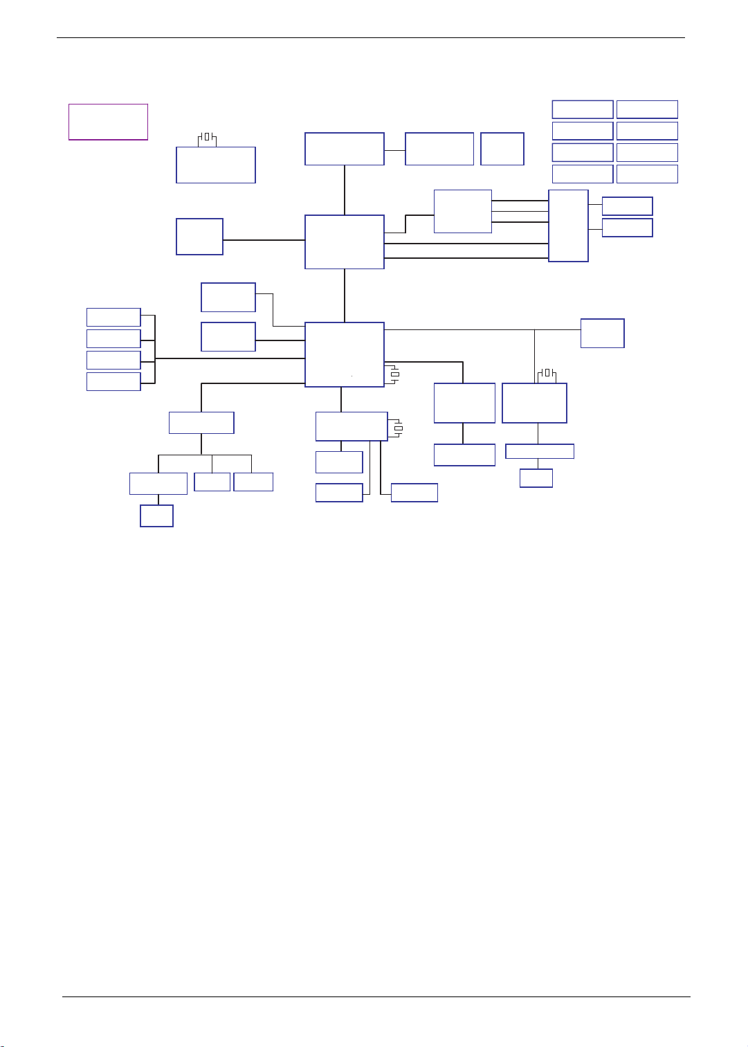
System Block Diagram
BOM MARK
IV@: INT VGA
EV@: STUFF FOR EXT VGA
SP@: STUFF FOR UMA or VGA
Ext USB Port x 2
USB 0,1
Int USB Port x 1
USB 7
Bluetooth
CCD
USB11
Audio Amplifier
G1453L
Int.
Speaker
X'TAL
14.318MHz
CLOCK GENERATOR
ICS:
SELGO: SLG8SP512TTR
DDRIII
HDD (SATA) *1
ODD (SATA)
Audio CODEC
(CX20561)
MIC Jack
Dual Channel DDR3
667/800 MHz
SATA0
SATA1
USB 2.0
Azalia
Int. MIC
Penryn 479
FSB
667/800/1067 Mhz
NB
Cantiga
X4 DMI interface
SB
ICH9M
LPC
EC (WPC775LDG)
SPI ROM
Touch Pad
Thermal Sensor
PCIE 16X
LVDS
RGB
PCI-Express
USB8
X'TAL
32.768KHz
X'TAL
32.768KHz
K/B COON.
NVIDIA
N10M-GE1
VRAM DDRII
512MB
Media
Cardreader
(RTS5159)
Card Reader
Connector
Fan Driver
EXT_LVDS
EXT_CRT
EXT_HDMI
INT_LVDS
INT_CRT
PCIE-1
PCIE-6
Atheros
Giga-LAN
(AR8131)
Transformer
RJ45
DDR3 PWR
TPS51116
THERMAL
PROTECTION
DISCHARGER
VGA CORE
OZ8118
SWITCH
CIRCUIT
X'TAL
25MHz
Mini Card
CHARGER
ISL6251
3/5V SYS PWR
ISL6237
CPU CORE PWR
OZ8116LN
+1.05V
UP6111AQDD
CRT
LVDS
4 Chapter 1
Page 15
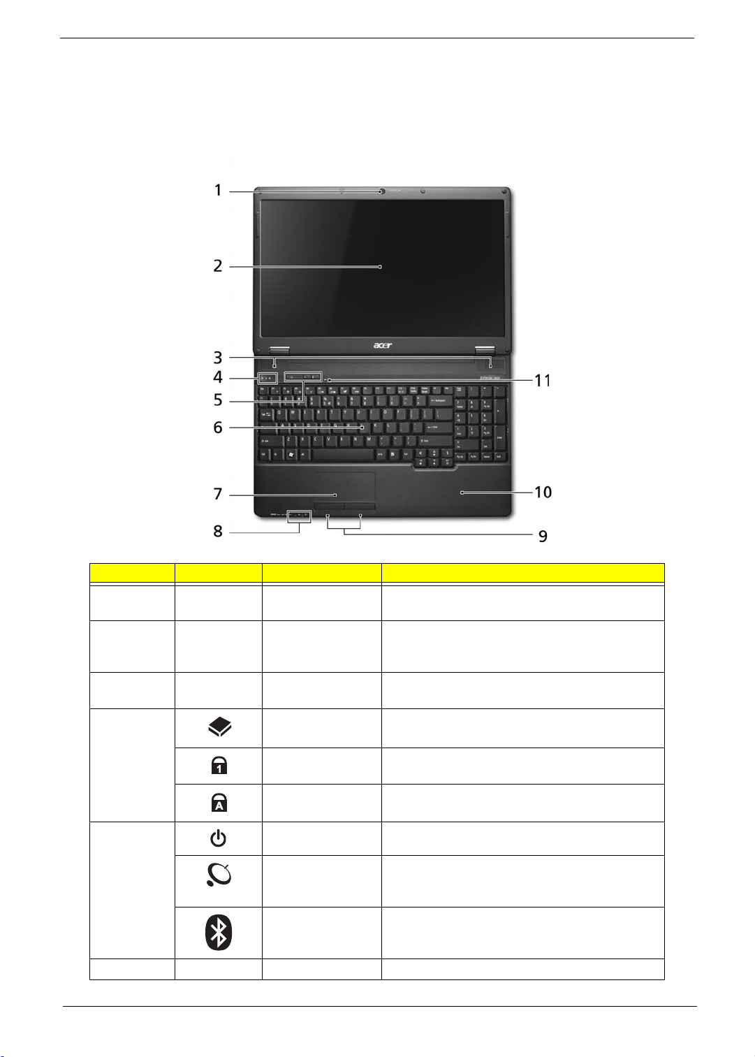
Acer Notebook tour
Front View
No. Icon Item Description
1 Acer Crystal Eye
webcam
2 Display screen Also called Liquid-Crystal Display (LCD),
3 Speakers Left and right speakers deliver stereo audio
4 HDD Indicates when the hard disk drive is
Num Lock Lights up when Num Lock is activated.
Caps Lock Lights up when Caps Lock is activated.
5 Power button Turns the computer on and off.
Wireless LAN
Communication
button / Indicator
Bluetooth
Communication
button/indicator
6 Keyboard For entering data into your computer.
Web camera for video communication (only for
certain models).
displays computer output (Configuration may
vary by models).
output.
active.
Enables/disables the wireless LAN function.
Indicates the status of wireless LAN
communication.
Enables/disables the Bluetooth function.
Indicates the status of Bluetooth
communication. (only for certain models)
Chapter 1 5
Page 16
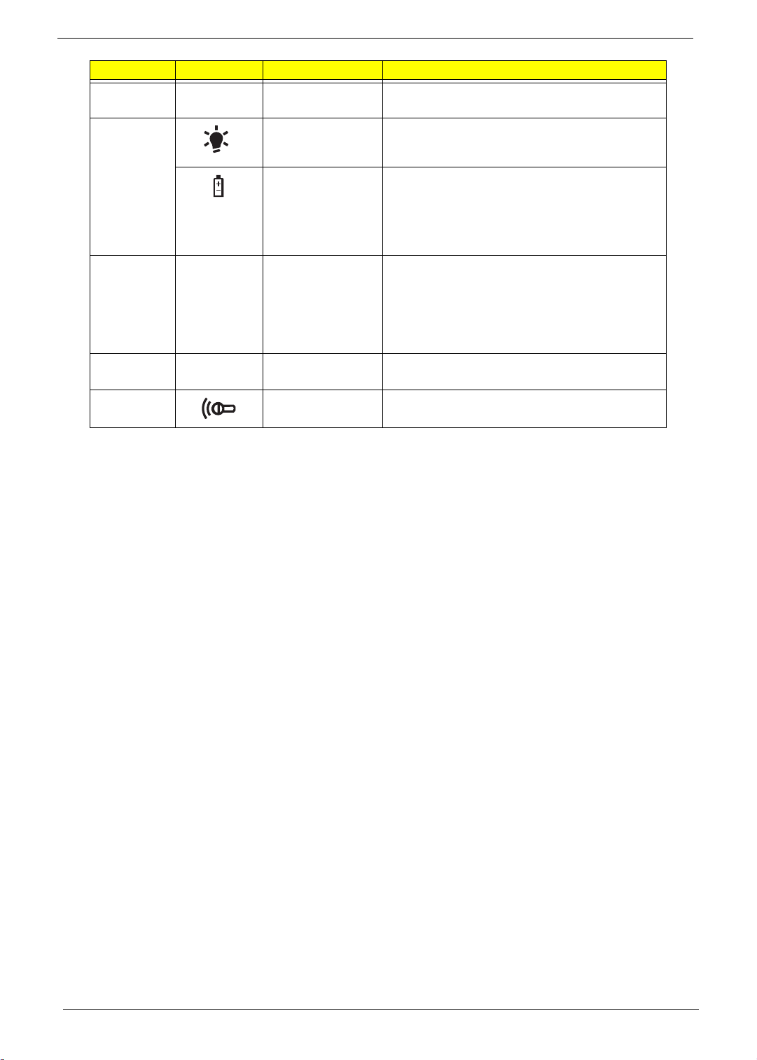
No. Icon Item Description
7 Touchpad Touch-sensitive pointing device which functions
like a computer mouse.
8 Power Indicates the computer's power status.
Battery Indicates the computer's battery status.
1. Charging: The light shows amber when the
battery is charging.
2. Fully charged: The light shows blue when in
AC mode.
9 Click buttons
(left, center* and
right)
10 Palmrest Comfortable support area for your hands when
11 Microphone Internal Microphone for sound recording
The left and right buttons function like the left
and right mouse buttons.
*The center button serves as Acer BioProtection fingerprint reader supporting Acer
FingerNav 4-way control function (only for
certain models).
you use the computer.
6 Chapter 1
Page 17
Hot Keys
The computer employs hotkeys or key combinations to access most of the computer's controls like screen
brightness and volume output.
To activate hotkeys, press and hold the <Fn> key before pressing the other key in the hotkey combination.
Hotkey Icon Function Description
<Fn> + <F1> Hotkey Help Displays help on hotkeys
<Fn> + <F2> System Properties Display the System Properties dialog box.
<Fn> + <F3> Power Options Display the Power Options Properties
dialog box.
<Fn> + <F4> Sleep Puts the computer in Sleep mode.
<Fn> + <F5> Display toggle Switches display output between the display
screen, external monitor (if connected) and
both.
<Fn> + <F6> Screen blank Turns the display screen backlight off to save
power. Press any key to return.
<Fn> + <F7> TouchPad toggle Turns the internal TouchPad on and off.
<Fn> + <F8> Speaker toggle Turns the speakers on and off.
<Fn> + < > Brightness up Increases the screen brightness.
<Fn> + < > Brightness down Decreases the screen brightness.
<Fn> + < >
<Fn> + < >
Volume up Increases the sound volume.
Volume down Decreases the sound volume.
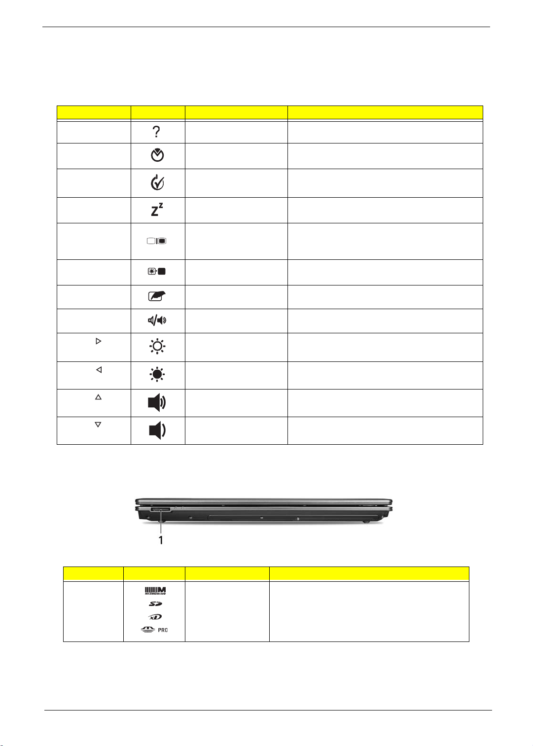
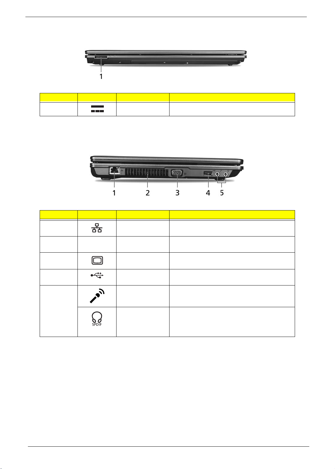
Closed Front View
No. Icon Item Description
1 5-in-1 card
reader
Accepts Secure Digital (SD), MultiMediaCard
(MMC), Memory Stick (MS), Memory Stick
PRO (MS PRO), xD-Picture Card (xD).
Note: Push to remove/install the card. Only
one card can operate at any given time.
Chapter 1 7
Page 18
Rear View
No. Icon Item Description
1 DC-in jack Connects to an AC adapter.
Left View
No. Icon Item Description
1 Ethernet (RJ-45)
port
2 Ventilation slots Enable the computer to stay cool, even after
3 External display
(VGA) port
4
5 Microphone jack Accepts inputs from external microphones.
USB 2.0 port Connect to USB 2.0 devices
Headphones/
speaker/line-out
jack with S/PDIF
support
Connects to an Ethernet 10/100/1000-based
network.
prolonged use.
Connects to a display device
(e.g. external monitor, LCD projector).
(e.g. USB mouse, USB camera)
Connects to audio line-out devices
(e.g., speakers, headphones).
8 Chapter 1
Page 19

Right View
No. Icon Item Description
1 USB 2.0 port Connect to USB 2.0 devices (e.g. USB mouse,
USB camera).
2 Optical drive Internal optical drive; accepts CDs or DVDs.
3 Optical disk access
indicator
4 Optical drive eject
button
5 Emergency eject
hole
Lights up when the optical drive is active.
Ejects the optical disk from the drive.
Ejects the optical drive tray when the computer is
turned off.
Note: Insert a paper clip into the emergency eject
hole to eject the optical drive tray when the
computer is off.
Bottom View
No. Icon Item Description
1 Battery bay Houses the computer's battery pack.
2 Battery release
latch
3 Hard disk bay Houses the computer's hard disk (secured with
4 Memory
compartment
Releases the battery for removal.
screws).
Houses the computer's main memory.
Chapter 1 9
Page 20

No. Icon Item Description
5 Battery lock Locks the battery in position.
6 Ventilation slots
and cooling fan
Enable the computer to stay cool, even after
prolonged use.
Note: Do not cover or obstruct the opening of the
fan.
10 Chapter 1
Page 21
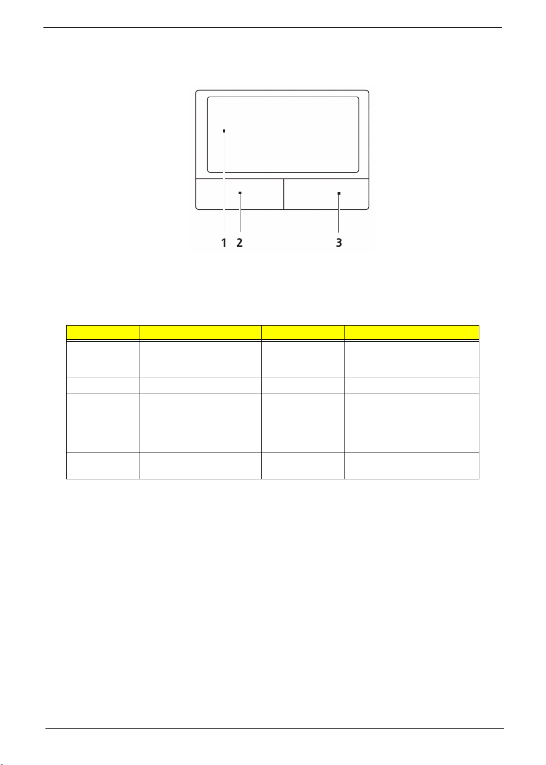
Touchpad Basics
The following items show you how to use the touchpad:
• Move your finger across the touchpad (1) to move the cursor.
• Press the left (2) and right (3) buttons located beneath the touchpad to perform selection and
execution functions. These two buttons are similar to the left and right buttons on a mouse.
Tapping on the touchpad is the same as clicking the left button.
Function Left Button (2) Right Button (4) Main touchpad (1)
Execute Quickly click twice. Tap twice (at the same speed
as double-clicking a mouse
button).
Select Click once. Tap once.
Drag Click and hold, then use
finger on the touchpad to
drag the cursor.
Access
context menu
Click once.
Tap twice (at the same speed
as double-clicking a mouse
button); rest your finger on
the touchpad on the second
tap and drag the cursor.
NOTE: When using the touchpad, keep it - and your fingers - dry and clean. The touchpad is sensitive to finger
movement; hence, the lighter the touch, the better the response. Tapping too hard will not increase the
touchpad’s responsiveness.
Chapter 1 11
Page 22
Using the Keyboard
The keyboard has full-sized keys and an embedded numeric keypad, separate cursor, lock, Windows, function
and special keys.
Lock Keys and embedded numeric keypad
The keyboard has three lock keys which you can toggle on and off.
Lock key Description
Caps Lock When Caps Lock is on, all alphabetic characters typed are in uppercase.
Num Lock
<Fn> + <F11>
Scroll Lock <Fn> +
<F12>
The embedded numeric keypad functions like a desktop numeric keypad. It is indicated by small characters
located on the upper right corner of the keycaps. To simplify the keyboard legend, cursor-control key symbols
are not printed on the keys.
Desired access Num Lock on Num Lock off
Number keys on
embedded keypad
Cursor-control keys on
embedded keypad
Main keyboard keys Hold <Fn> while typing letters on
When Num Lock is on, the embedded keypad is in numeric mode. The keys
function as a calculator (complete with the arithmetic operators +, -, *, and /). Use
this mode when you need to do a lot of numeric data entry. A better solution
would be to connect an external keypad.
When Scroll Lock is on, the screen moves one line up or down when you press
the up or down arrow keys respectively. Scroll Lock does not work with some
applications.
Type numbers in a normal manner.
Hold <Shift> while using cursor-
control keys.
embedded keypad.
Hold <Fn> while using cursor-
control keys.
Type the letters in a normal
manner.
12 Chapter 1
Page 23

Windows Keys
The keyboard has two keys that perform Windows-specific functions.
Key Description
Windows key Pressed alone, this key has the same effect as clicking on the Windows Start button;
it launches the Start menu. It can also be used with other keys to provide a variety of
functions:
<>: Open or close the Start menu
<> + <D>: Display the desktop
<> + <E>: Open Windows Explore
<> + <F>: Search for a file or folder
<> + <G>: Cycle through Sidebar gadgets
<> + <L>: Lock your computer (if you are connected to a network domain), or
switch users (if you're not connected to a network domain)
<> + <M>: Minimizes all windows
<> + <R>: Open the Run dialog box
<> + <T>: Cycle through programs on the taskbar
<> + <U>: Open Ease of Access Center
<> + <X>: Open Windows Mobility Center
<> + <BREAK>: Display the System Properties dialog box
<> + <SHIFT+M>: Restore minimized windows to the desktop
<> + <TAB>: Cycle through programs on the taskbar by using Windows Flip 3-D
<> + <SPACEBAR>: Bring all gadgets to the front and select Windows Sidebar
Application
key
<CTRL> +
<CTRL> + <> + <TAB>: Use the arrow keys to cycle through programs on the
Note: Depending on your edition of Windows Vista, some shortcuts may not function
This key has the same effect as clicking the right mouse button; it opens the
application's context menu.
<> + <F>: Search for computers (if you are on a network)
taskbar by using Windows Flip 3-D
as described.
Chapter 1 13
Page 24

Special Key
You can locate the Euro symbol and the US dollar sign at the upper-center and/or bottom-right of your
keyboard.
The Euro symbol
1. Open a text editor or word processor.
2. Hold <Alt Gr> and then press the <5> key at the upper-center of the keyboard.
NOTE: Note: Some fonts and software do not support the Euro symbol. Please refer to www.microsoft.com/
typography/faq/faq12.htm for more information.
The US dollar sign
1. Open a text editor or word processor.
2. Hold <Shift> and then press the <4> key at the upper-center of the keyboard.
NOTE: This function varies by the operating system version.
14 Chapter 1
Page 25
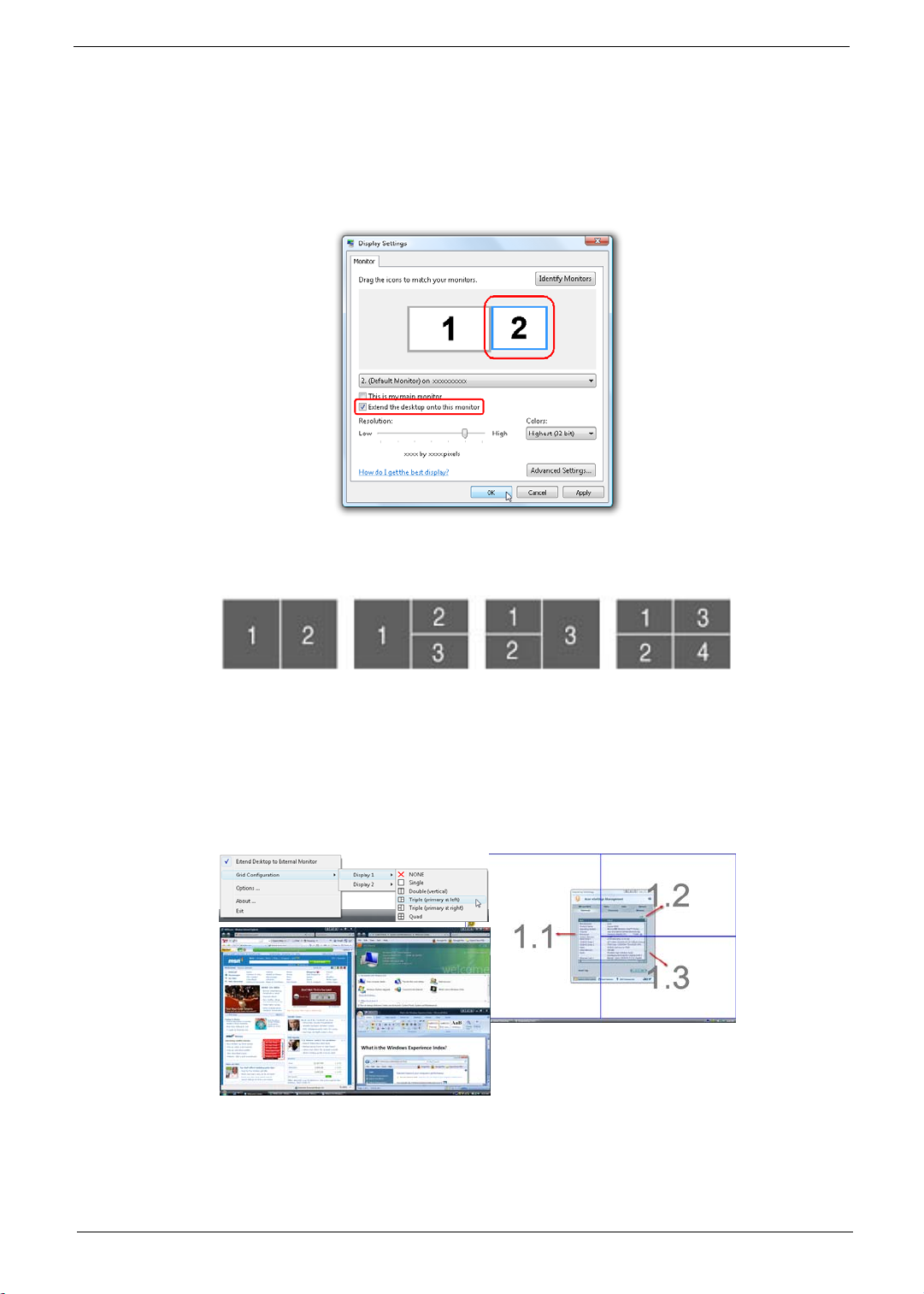
Acer GridVista (dual-display compatible)
NOTE: This feature is only available on certain models.
To enable the dual monitor feature of the notebook, first ensure that the second monitor is connected, then
select Start, Control Panel, Display and click on Settings. Select the secondary monitor (2) icon in the
display box and then click the check box Extend my windows desktop onto this monitor. Finally, click
Apply to confirm the new settings and click OK to complete the process.
Acer GridVista is a handy utility that offers four pre-defined display settings so you can view multiple windows
on the same screen. To access this function, please go to Start´ All Programs and click on Acer GridVista.
You may choose any one of the four display settings indicated below:
Double (vertical), Triple (primary at left), Triple (primary at right), or Quad Acer Gridvista is dual-display
compatible, allowing two displays to be partitioned independently.
Acer Gridvista is dual-display compatible, allowing two displays to be partitioned independently.
AcerGridVista is simple to set up:
1. Run Acer GridVista and select your preferred screen configuration for each display from the task bar.
2. Drag and drop each window into the appropriate grid.
3. Enjoy the convenience of a well-organized desktop.
NOTE: Please ensure that the resolution setting of the second monitor is set to the manufacturer's
recommended value.
Chapter 1 15
Page 26
Hardware Specifications and Configurations
Processor
Item Specification
CPU Manufacturer Intel
CPU package Micro-FCPGA packaging, 479-pin
Core Logic • NB Chipset Intel CS GM45NB / PM45NB
• SB Chipset Intel CS ICH9M
Chipset • ENE KB926 for Keyboard Controller, Battery management
Unit, and RTC.
• Integrated VGA solution for Intel 945GSE.
• Realtek ALC272X-GR for High Definition Audio Codec.
• Atheros AR8114A for 10/100 LAN
Features • Dual-core processor for mobile with enhanced performance
• Supports Intel® architecture with Intel® Wide Dynamic
Execution
• Supports L1 cache-to-cache (C2C) transfer
• On-die, primary 32-kB instruction cache and 32-kB write-back
data cache in each core
• The Penryn processor in XE, SV and LV have an On-die, up to
6-MB second-level shared cache with Advanced Transfer
Cache architecture
• The Penryn processor in ULV have an On-die, up to 3-MB
second-level shared cache with Advanced Transfer Cache
architecture
• Streaming SIMD extensions 2 (SSE2), streaming SIMD
extensions 3 (SSE3), supplemental streaming SIMD
extensions 3 (SSSE3) and SSE4.1 instruction sets
• The Penryn processor in XE, SV and LV are offered at 667MHz, 800-MHz and 1066-MHz source-synchronous front side
bus (FSB)
• The Penryn processor in ULV are offered at 667-MHz and 800MHz source synchronous front side bus (FSB)
• Advanced power management features including Enhanced
Intel SpeedStep® Technology and dynamic FSB frequency
switching
• Digital thermal sensor (DTS)
• Intel® 64 architecture
• Supports enhanced Intel® Virtualization Technology
• Intel® Dynamic Acceleration Technology and Enhanced Multi
Threaded
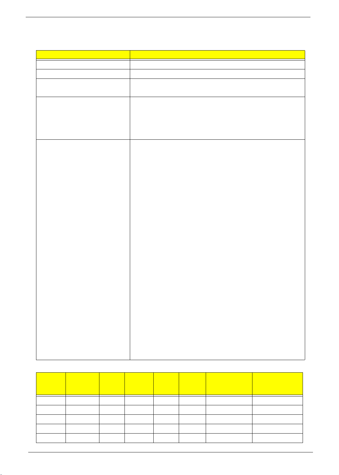
Processor Specifications
Item
P7450 2.13 GHz 2 1066 45 nm 3 MB Micro-FCPGA
P8600 2.4 GHz 2 1066 45 nm 3 MB Micro-FCPGA
P8700 2.53 GHz 2 1066 45 nm 3 MB Micro-FCPGA
P9500 2.53 GHz 2 1066 45 nm 6 MB Micro-FCPGA
T6400 2.0 GHz 2 800 45 nm 3 MB Micro-FCPGA
16 Chapter 1
CPU
Speed
Cores
Bus
Speed
(MHz)
Mfg.
Tech
Cache
Size
Package P/N
Page 27
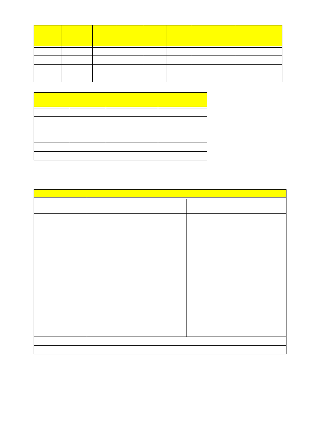
Item
T6600 2.2 GHz 2 800 45 nm 2 MB Micro-FCPGA
T9550 2.66 GHz 2 1066 45 nm 6 MB Micro-FCPGA
T9600 2.8GHz 2 1066 45 nm 6 MB Micro-FCPGA
T9800 2.93 GHz 2 1066 45 nm 6 MB Micro-FCPGA
CPU Fan Tru Value Table
CPU Temperature at
33 38 2700 28
40 45 3000 31
52 47 3300 34
60 67 3800 37
72 75 4000 40
92 89 4800
• Throttling 50%: On= 84°C; OFF=86°C
• OS shut down at 100°C; H/W shut down(PH1) at 110°C
Graphics
Graphics
processor
Specifications • Supports multi-mode DisplayPort,
Display support Dual independent display support
Colors 16.7 million colors
CPU
Speed
Diode (°C)
Item Specification
Cores
NVIDIA® N10M-GE1 Mobile Intel® GM45/GL40 Express
in addition to TMDS (DVI and
HDMI) and LVDS
• Capable of running at next
generation PCI Express 2.0
speeds.
• DX10 graphics hardware leverages
the extremely efficient unified
shader architecture introduced by
NVIDIA with the GeForce NB8x
family of products.
• Enabled with PureVideo HD
technology, providing the highest
video quality while at the same time
minimizing CPU utilization for video
playback, especially for the latest
video-intensive HDDVD and BluRay content.
Bus
Speed
(MHz)
Fan Speed (RPM) SPL Spec (dBA)
Mfg.
Tech
Cache
Size
Chipset
• Integrated 3D graphics, featuring
• Up to 1759 MB of Intel® Dynamic
• Supports Microsoft® DirectX® 10
Package P/N
Intel® Graphics Media Accelerator
4500MHD (Intel® GMA 4500MHD)
Video Memory Technology 5.0 (128
MB of dedicated video memory, up
to 1631 MB of shared system
memory)
Chapter 1 17
Page 28
Item Specification
External
resolution/refresh
rate
• 2048 x 1536: 75/60 Hz
• 1920 x 1440: 85/75/60 Hz
• 1920 x 1200: 75/60 Hz
• 1920 x 1080: 100/85/75/60 Hz
• 1680 x 945: 100/85/75/60 Hz
• 1600 x 1200: 120/100/85/75/60 Hz
• 1600 x 900: 120/100/85/75/60 Hz
• 1400 x 1050: 85/75/60 Hz
• 1366 x 768: 85/75/60 Hz
• 1280 x 1024: 120/100/85/75/60 Hz
• 1280 x 960: 85/75/60 Hz
• 1280 x 768: 85/75/60 Hz
• 1280 x 720: 100/85/75/60 Hz
• 1024 x 768: 120/100/85/75/60 Hz
• 800 x 600: 120/100/85/72/60 Hz
Supported
interfaces
• MPEG-2/DVD decoding
• WMV9 (VC-1) and H.264 (AVC) decoding
• HDMI™ (High-Definition Multimedia Interface) with HDCP (High-bandwidth
Digital Content Protection) support
• DisplayPort™ support
System Memory
Item Specification
Memory controller Built in
Memory size N/A
DIMM socket number 2
Supports memory size per socket 2 GB
Supports maximum memory size 4 GB
Supports DIMM type JEDEC 204-pin SODIMM, 67.75”x 30.15”x 3.8”(Max)n
Supports DIMM Speed DDR 3-800/1066 Mhz
System Storage
Item Specification
HDD • 9.5mm height, 2.5" HDD
• Easily removable with no more than four screws
• SATA bus
• 160-500GB
• 5400 rpm
• SATA connector BTO
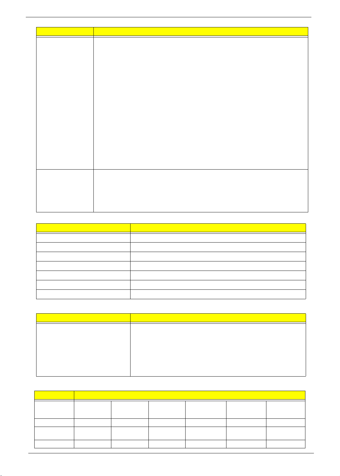
Hard Disk Drive Interface
Item Hard Disk Specification
Vendor &
Model Name
Capacity (GB) 160 250 320 500 160 250
Bytes per
sector
Data heads 2 2 4 4 2 2
Seagate
ST9160310AS
512 512 512 512 512 512
Seagate
ST9250315AS
Seagate
ST9320320AS
Seagate
ST9500325AS
Hitachi
HTS545016B9A
300
Hitachi
HTS545025B9
A300
18 Chapter 1
Page 29
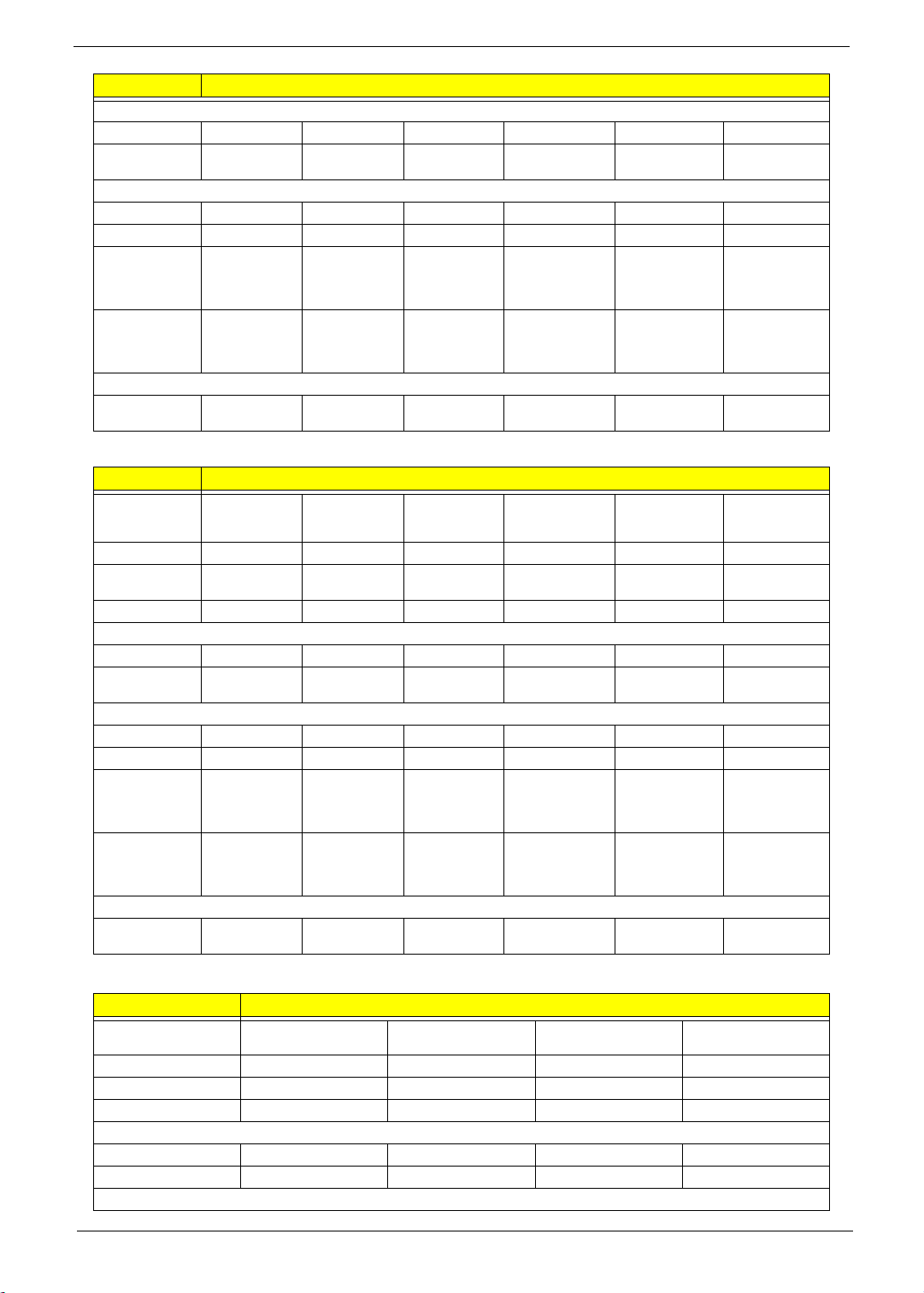
Item Hard Disk Specification
Drive Format
Disks 1 1 2 2 1 1
Spindle speed
(RPM)
Performance Specifications
Buffer size 8 MB 8 MB 8MB 8 MB 8 MB 8MB
In ter face S ATA SATA SATA S ATA S ATA SATA
Fast data
transfer rate
(Mbits/sec,
max)
Media data
transfer rate
(Mbytes/sec
max)
DC Power Requirements
Voltage
tolerance
5400 5400 5400 5400 5400 5400
830
300 300 300 300 300 300
5V ±5% 5V ±5% 5V ±5% 5V ±5% 5V ±5% 5V ±5%
1175 830 1175 845 875
Item Hard Disk Specification
Vendor &
Model Name
Capacity (GB) 320 500 160 250 320 500
Bytes per
sector
Data heads 2 4 2 2 4 4
Drive Format
Disks 1 2 1 1 2 2
Spindle speed
(RPM)
Performance Specifications
Buffer size 8 MB 8 MB 8MB 8 MB 8 MB 8MB
In ter face S ATA SATA SATA S ATA S ATA SATA
Fast data
transfer rate
(Mbits/sec,
max)
Media data
transfer rate
(Mbytes/sec
max)
DC Power Requirements
Voltage
tolerance
Hitachi
HTS545032B9
A300
512 512 512 512 512 512
5400 5400 5400 5400 5400 5400
875 875 363 ~ 952
300 300 300 300 300 300
5V ±5% 5V ±5% 5V ±5% 5V ±5% 5V ±5% 5V ±5%
Hitachi
HTS545050B9
A300
To sh i ba
MK1655GSX
typical
To sh i ba
MK2555GSX
363 ~ 952
typical
To sh ib a
MK3255GSX
363 ~ 952
typical
To sh i ba
MK5055GSX
363 ~ 952
typical
Item Hard Disk Specificati o n
Vendor & Model Name
Capacity (GB) 160 250 320 500
Bytes per sector 512 512 512 512
Data heads 2434
Drive Format
Disks1222
Spindle speed (RPM) 5400 5400 5400 5400
Performance Specifications
Western Digital
WD1600BEVT-22ZCTO
Western Digital
WD2500BEVT-22ZCT0
Western Digital
WD3200BEVT-22ZCT0
Western Digital
WD5000BEVT-22ZAT0
Chapter 1 19
Page 30
Item Hard Disk Specificati o n
Buffer size 8 MB 8 MB 8MB 8 MB
In terf ace S ATA SATA S ATA S ATA
Fast data transfer rate
(Mbits/sec, max)
Media data transfer
rate
(Mbytes/sec max)
DC Power Requirements
Voltage tolerance 5V ±5% 5V ±5% 5V ±5% 5V ±5%
N/A N/A N/A N/A
300 300 300 300
Optical Disk Drive
Item Specification
Manufacturer Sony 30656330, PLDS Corp., TS-L633B, Panasonic UJ880ADAA-A
Type 8X DVD-Super Multi double-layer drive
Performance Specification
Transfer rate (MB/
10.8
sec)
Buffer Memory 2MB
Read/write speeds Read: 24X CD-ROM, 24X CD-R, 24X CD-RW, 8X DVD-ROM, 8X DVD-R, 8X
DVD+R, 6X DVD-ROM DL (double-layer), 6X DVD-R DL (double-layer), 6X DVD+R
DL (double-layer), 6X DVD-RW, 6X DVD+RW, 5X DVD-RAM
·Write: 24X CD-R, 16X CD-RW, 8X DVD-R, 8X DVD+R, 4X DVD-R DL (double-
layer), 4X DVD+R DL (double-layer), 6X DVD-RW, 8X DVD+RW, 5X DVD-RAM
Interface SATA
Loading mechanism Drawer-Type
Power Requirement
Input Voltage DC 5 V +/- 5%
BIOS
Item Specification
BIOS vendor Phoenix
BIOS Version V0.3207C
BIOS ROM type Flash
BIOS ROM size 16 MB
LCD 10.1”
Item Specification
Vendor/model name AU Optronics Chi Mei Samsung LG
Screen Diagonal (mm) 391 391 391 354.95
Active Area (mm) 344.2 X 193.5 344.232 X
193.536
344.232 X
193.536
309.40 X
173.95
Display resolution (pixels) 1366x768 1366x768 1366x768 1366x768
Pixel Pitch (mm) 0.252X0.252 0.252X0.252 0.252X0.252 0.2265X0.226
5
2
220 220 220 220
Typical White Luminance (cd/m
)
also called Brightness
Contrast Ratio 500 500 500 500
Response Time (Optical Rise
88258
Time/Fall Time) msec
20 Chapter 1
Page 31

Item Specification
Typical Power Consumption
(watt)
Weight (without inverter) 450 355 360 350
Physical Size (mm) 360x210x5.5 359.3x209.5x
Electrical Interface 1 ch. LVDS 1 ch. LVDS LVDS LVDS
Viewing Angle (degree)
Horizontal (Right)/CR = 10 (Left)
Vertical (Upper)/CR = 10 (Lower)
Audio Interface
Item Specifications
Audio Controller • Conexant CX-20561-15Z Azalia Codec
• Amplifier GMT G1441
Audio onboard or option Built-in
Mono or Stereo Stereo
Resolution 2.1
Compatibility Headphone-out with S/PDIF, Line-In and Microphone-In.2 stereo ADCs
support 16/20/24-bit PCM format recording simultaneously.
Sampling Rate. All DACs supports 16/20/24-bit, 44.1k/48k/96k/192kHz sample rate.All
ADCs supports 16/20/24-bit, 44.1k/48k/96k/192kHz sample rate.Two
independent S/PDIF-OUT converters support 16/20/24-bit, 44.1k/48k/88.2k/
96k/192kHz sample rate. One for normal S/PDIF output, the other one
output an independent digital stream to HDMI transmitter.
Internal Microphone • Digital MICRO PHONE ZK2(HFM-M101-006-L19-G)
• Digital MICRO PHONE ZK2(A-OA2408FM-018)
Internal speaker/
Quantity
Two Med-High Speakers (2W/4Ohm) and one Subwoofer (3W/4Ohm)
5.6 5.3 4.9 4.5
45/45 (typical)
15/35 (typical)
5.2
45/45 (typical)
20/45 (typical)
359.3x209.5x
5.5
45/45 (typical)
15/35 (typical)
324x192.5x5.
2
40/40 (min)
10/30 (min)
LAN Interface
Item Specification
LAN Chipset Atheros AL8131L-Al1E-R/AL008131002 Gigabit Ethernet
LAN Controller
Features • Combines a 10/100/1000BASE-T GbE media access
controller (MAC), a triple-speed Ethernet physical layer
transceiver (PHY), and a PCI Express bus interface.
• Compliant with IEEE 802.3u specification for 10/
100Mbps Ethernet and IEEE 802.3ab specification for
1000Mbps Ethernet.
• Combines pulse shaping, Tx/Rx PCS, echo canceller,
NEXT canceller, equalizer, decoder, and timing recovery
functions to deliver robust signal performance in noisy
environments.
• Supports checksum offload features for IP, TCP, and
UDP, lowering CPU utilization and optimizing network
performance.
• Supports advanced power management functions,
including Wake-On-LAN (WOL) and AMD Magic
Packet™
Chapter 1 21
Page 32

Keyboard
Item Specification
Type Flat keyboard
Total number of keypads 84
Windows logo key Yes
Internal & external keyboard work
simultaneously
Mini Card
Item Specification
Number Supported 2
Features • 2 mini card slot (1 for 3G / WiMax (full-size) and 1 for
3G Card
Item Specification
Features • 3G card in mini card slot for 3G/ WiMAX (full-size)
Plug USB keyboard to the USB port directly: Yes
WLAN (half-size)
• Embedded 3G module and built-in 2 antenna (combo
wireless + 3G) on top of LCD
• Control by USB interface
• User accessible SIM card by battery removal
• Antenna: Has to be placed on the sides of LCD in A/B
cover
Bluetooth interface
Item Specification
Chipset • FOXCON T60H928.01 LF Bluetooth miniUSB module
Features • Embedded USB solution with antenna
• Bluetooth 2.0+EDR
• Bluetooth control for BT optical mouse
Wireless LAN
Item Specification
Type IEEE802.11 b/g Half PCI-e Card
Features • IEEE 802.11 b/g
• PCI-Express Half Mini card (H2 type)
Battery
Item Specification
Vendor & model name SANYO UM-2008BW, PANASONIC UM-2008B, SIMPLO
UM-2008A
Battery Type Li-ion
Pack capacity 4400/5800 mAh
Number of battery cell 6
Package configuration 3S2P
22 Chapter 1
Page 33

Chapter 2
System Utilities
BIOS Setup Utility
The BIOS Setup Utility is a hardware configuration program built into your computer’s BIOS (Basic Input/
Output System).
Your computer is already properly configured and optimized, and you do not need to run this utility. However, if
you encounter configuration problems, you may need to run Setup. Please also refer to Chapter 4
Troubleshooting if a problem arises.
To activate the BIOS Utility, press F2 during POST (when Press <F2> to enter Setup message is prompted
on the bottom of screen).
Press F2 to enter setup. The default parameter of F12 Boot Menu is set to “disabled”. If you want to change
boot device without entering BIOS Setup Utility, please set the parameter to “enabled”.
Press <F12> during POST to enter multi-boot menu. In this menu, user can change boot device without
entering BIOS SETUP Utility.
Navigating the BIOS Utility
There are six menu options: Information, Main, Advanced, Security, Power, Boot, and Exit.
Follow these instructions:
• To choose a menu, use the left and right arrow keys.
• To choose an item, use the up and down arrow keys.
• To change the value of a parameter, press F5 or F6.
• A plus sign (+) indicates the item has sub-items. Press Enter to expand this item.
• Press Esc while you are in any of the menu options to go to the Exit menu.
• In any menu, you can load default settings by pressing F9. You can also press F10 to save any
changes made and exit the BIOS Setup Utility.
NOTE: You can change the value of a parameter if it is enclosed in square brackets. Navigation keys for a
particular menu are shown on the bottom of the screen. Help for parameters are found in the Item
Specific Help part of the screen. Read this carefully when making changes to parameter values. Please
note that system information is subject to different models.
Chapter 2 23
Page 34

Information
The Information screen displays a summary of your computer hardware information.
Phoenix SecureCore(tm) Setup Utility
Main Boot
SecurityInformation
Exit
CPU Type
CPU Type
CPU Speed
CPU Speed
IDE0 Model Name:
IDE0 Model Name:
IDE0 Serial Number:
IDE0 Serial Number:
ATAPI Model Name:
ATAPI Model Name:
System BIOS Version:
System BIOS Version:
VGA BIOS Version:
VGA BIOS Version:
Serial Number:
Serial Number:
Asset Tag Number:
Asset Tag Number:
Product Name:
Product Name:
Manufacturer Name:
Manufacturer Name:
UUID:
UUID:
Help
F1
Exit
ESC
NOTE: The system information is subject to different models.
Parameter Description
CPU Type This field shows the CPU type of the system.
CPU Speed This field shows the speed of the CPU.
IDE0 Model Name This field shows the model name of HDD installed on primary IDE master.
IDE0 Serial Number This field displays the serial number of HDD installed on primary IDE master.
System BIOS Version Displays system BIOS version.
VGA BIOS Version This field displays the VGA firmware version of the system.
Serial Number This field displays the serial number of this unit.
Asset Tag Number This field displays the asset tag number of the system.
Product Name This field shows product name of the system.
Manufacturer Name This field displays the manufacturer of this system.
UUID Number Universally Unique Identifier (UUID) is an identifier standard used in software
Select Item
Select Menu
construction, standardized by the Open Software Foundation (OSF) as part of
the Distributed Computing Environment (DCE).
Intel(R) Core(TM)2 Duo CPU P6570 @ 2.10GHz
Intel(R) Core(TM)2 Duo CPU P6570 @ 2.10GHz
2100MHz
2100MHz
WDC WD3200BEVT-22ZCT0
WDC WD3200BEVT-22ZCT0
WD-WXEZ08P30288
WD-WXEZ08P30288
Optiarc DVD RW AD-7580S
Optiarc DVD RW AD-7580S
V0.3207C
V0.3207C
nVidia 62.98.61.00.F9
nVidia 62.98.61.00.F9
Z060SK03C190917A7D2500
Z060SK03C190917A7D2500
Acer
Acer
C0343F08AB34E45B45CD12447670098B8
C0343F08AB34E45B45CD12447670098B8
F5/F6
Enter
Change Values
Select SubMenu
Setup Default
F9
Save and Exit
F10
24 Chapter 2
Page 35

Main
The Main screen allows the user to set the system time and date as well as enable and disable boot option
and recovery.
Phoenix SecureCode(tm) Setup Utility
Boot
Exit
Item Specific Help
<Tab>, <Shift-Tab>, or
<Enter> selects field.
System Time:
System Time:
System Date:
System Date:
Total Memory:
Total Memory:
Video Memory:
Video Memory:
SecurityInformation
[10:49:59]
[10:49:59]
[03/03/2009]
[03/03/2009]
4094 MB
4094 MB
512 MB
512 MB
PowerMain
Quiet Boot
Quiet Boot
Network Boot
Network Boot
F12 Boot Menu
F12 Boot Menu
D2D Recovery
D2D Recovery
SATA Mode
SATA Mode
Help
F1
Exit
ESC
NOTE: The screen above is for your reference only. Actual values may differ.
The table below describes the parameters in this screen. Settings in boldface are the default and suggested
parameter settings.
Parameter Description Format/Option
System Time Sets the system time. The hours are displayed with 24-
System Date Sets the system date. Format MM/DD/YYYY
Total Memory This field reports the memory size of the system.
Video Memory
Quiet Boot Allows startup to skip certain tests while booting,
Network Boot Enables, disables the system boot from LAN (remote
F12 Boot Menu Enables, disables Boot Menu during POST. Option: Enabled or Disabled
D2D Recovery Enables, disables D2D Recovery function. The function
SATA Mode Control the mode in which the SATA controller should
Select Item
Select Menu
hour format.
Memory size is fixed to 4094MB.
Shows the video memory size.
decreasing the time needed to boot the system.
server).
allows the user to create a hidden partition on hard disc
drive to store operation system and restore the system
to factory defaults.
operate.
[Enabled]
[Enabled]
[Enabled]
[Enabled]
[Disabled]
[Disabled]
[Enabled]
[Enabled]
[AHCI Mode]
[AHCI Mode]
F5/F6
Enter
Change Values
Select SubMenu
Setup Default
F9
Save and Exit
F10
Format: HH:MM:SS
(hour:minute:second)
(month/day/year)
N/A
N/A
Option: Enabled or Disabled
Option: Enabled or Disabled
Option: Enabled or Disabled
Option: AHCI or IDE
Chapter 2 25
Page 36

Security
The Security screen contains parameters that help safeguard and protect your computer from unauthorized
use.
Phoenix SecureCore(tm) Setup Utility
Information
Supervisor Password Is:
Supervisor Password Is:
User Password Is:
User Password Is:
HDD Password Is:
HDD Password Is:
Set Supervisor Password
Set Supervisor Password
Set User Password
Set User Password
Set Hdd Password
Set Hdd Password
Password on Boot
Password on Boot
Main Boot
Security
Clear
Clear
Clear
Clear
Clear
Clear
[Enter]
[Enter]
[Enter]
[Enter]
[Enter]
[Enter]
[Disabled]
[Disabled]
Exit
Item Specific Help
Supervisor Password
controls access to the
setup utility.
Help
F1
Exit
ESC
The table below describes the parameters in this screen. Settings in boldface are the default and suggested
parameter settings.
Parameter Description Option
Supervisor Password Is Shows the setting of the Supervisor password Clear or Set
User Password Is Shows the setting of the User password. Clear or Set
HDD Password Is Shows the setting of the HDD password. Clear or Set
Set Supervisor Password Press Enter to set the supervisor password. When
Set User Password Press Enter to set the user password. When user
Set Hdd Password Enter HDD password.
Power on password Defines whether a password is required or not while
Select Item
Select Menu
set, this password protects the BIOS Setup Utility
from unauthorized access. The user can not either
enter the Setup menu nor change the value of
parameters.
password is set, this password protects the BIOS
Setup Utility from unauthorized access. The user can
enter Setup menu only and does not have right to
change the value of parameters.
the events defined in this group happened. The
following sub-options are all requires the Supervisor
password for changes and should be grayed out if the
user password was used to enter setup.
F5/F6
Enter
Change Values
Select SubMenu
Setup Default
F9
Save and Exit
F10
Enabled or
Disabled
NOTE: When you are prompted to enter a password, you have three tries before the system halts. Don’t forget
your password. If you forget your password, you may have to return your notebook computer to your
dealer to reset it.
26 Chapter 2
Page 37

Setting a Password
Follow these steps as you set the user or the supervisor password:
1. Use the ↑ and ↓ keys to highlight the Set Supervisor Password parameter and press the Enter key. The
Set Supervisor Password box appears:
Set Supervisor Password
Enter New Password [ ][ ]
Confirm New Password [ ]
2. Type a password in the “Enter New Password” field. The password length can not exceeds 8
alphanumeric characters (A-Z, a-z, 0-9, not case sensitive). Retype the password in the “Confirm New
Password” field.
IMPORTANT:Be very careful when typing your password because the characters do not appear on the screen.
3. Press Enter. After setting the password, the computer sets the User Password parameter to “Set”.
4. If desired, you can opt to enable the Password on boot parameter.
5. When you are done, press F10 to save the changes and exit the BIOS Setup Utility.
Removing a Password
Follow these steps:
1. Use the ↑ and ↓ keys to highlight the Set Supervisor Password parameter and press the Enter key. The
Set Password box appears:
Set Supervisor Password
Enter Current Password [ ][ ]
Enter New Password [ ]
Confirm New Password [ ][ ]
2. Type the current password in the Enter Current Password field and press Enter.
3. Press Enter twice without typing anything in the Enter New Password and Confirm New Password fields.
The computer then sets the Supervisor Password parameter to “Clear”.
4. When you have changed the settings, press u to save the changes and exit the BIOS Setup Utility.
Chapter 2 27
Page 38

Changing a Password
1. Use the ↑ and ↓ keys to highlight the Set Supervisor Password parameter and press the Enter key. The
Set Password box appears.
Set Supervisor Password
Enter Current Password [ ][ ]
Enter New Password [ ]
Confirm New Password [ ][ ]
2. Type the current password in the Enter Current Password field and press Enter.
3. Type a password in the Enter New Password field. Retype the password in the Confirm New Password
field.
4. Press Enter. After setting the password, the computer sets the User Password parameter to “Set”.
5. If desired, you can enable the Password on boot parameter.
6. When you are done, press F10 to save the changes and exit the BIOS Setup Utility.
If the verification is OK, the screen will display as following.
Setup Notice
Changes have been saved.
[Continue][ Continue]
The password setting is complete after the user presses Enter.
If the current password entered does not match the actual current password, the screen will show you the
Setup Warning.
Setup Warning
Invalid Password.
[Continue][ Continue]
If the new password and confirm new password strings do not match, the screen displays the following
message.
Setup Warning
Passwords do not match.
Re-enter password.
[Continue][ Continue]
28 Chapter 2
Page 39

Boot
This menu allows the user to decide the order of boot devices to load the operating system. Bootable devices
includes USB drives, the onboard hard disk drive and the DVD drive in the module bay.
Phoenix SecureCore(tm) Setup Utility
Information
Boot priority order:
Boot priority order:
1. IDE0 : WDC WD3200BEVT-22ZCT0-(S1)
1. IDE0 : WDC WD3200BEVT-22ZCT0-(S1)
2. IDE CD : Optiarc DVD RW AD-7580S
2. IDE CD : Optiarc DVD RW AD-7580S
3. PCI LAN: Atheros Boot Agent
3. PCI LAN: Atheros Boot Agent
4. USB HDD :
4. USB HDD :
5. USB CDROM :
5. USB CDROM :
6. USB FDC :
6. USB FDC :
7. USB KEY :
7. USB KEY :
8:
8:
Excluded from boot order:
Excluded from boot order:
Main Boot
Security
Exit
Item Specific Help
Keys used to view or
configure devices:
Up and Down arrows
select a device.
<+> and <-> moves
the device up or down.
<f> and <r> specifies
the device fixed or
removable.
<x> exclude or include
the device to boot.
<Shift+1>enables or
disables a device.
<1 - 4> Loads default
boot sequence.
F1
ESC
Help
Exit
Select Item
Select Menu
F5/F6
Enter
Change Values
Select SubMenu
Setup Default
F9
Save and Exit
F10
Chapter 2 29
Page 40

Exit
The Exit screen allows you to save or discard any changes you made and quit the BIOS Utility.
Phoenix SecureCore(tm) Setup Utility
Information
Exit Saving Changes
Exit Saving Changes
Exit Discarding Changes
Exit Discarding Changes
Load Setup Defaults
Load Setup Defaults
Discard Changes
Discard Changes
Save Changes
Save Changes
Main Boot
Security
Exit
Item Specific Help
Exit System Setup and
save your changes to
CMOS.
Help
F1
Exit
ESC
The table below describes the parameters in this screen.
Parameter Description
Exit Saving Changes Exit System Setup and save your changes to CMOS.
Exit Discarding
Changes
Load Setup Default Load default values for all SETUP item.
Discard Changes Load previous values from CMOS for all SETUP items.
Save Changes Save Setup Data to CMOS.
Select Item
Select Menu
Exit utility without saving setup data to CMOS.
F5/F6
Enter
Change Values
Execute Command
F9
F10
Setup Default
Save and Exit
30 Chapter 2
Page 41

BIOS Flash Utility
The BIOS flash memory update is required for the following conditions:
• New versions of system programs
• New features or options
• Restore a BIOS when it becomes corrupted.
Use the Flash16 utility to update the system BIOS flash ROM.
NOTE: Do not install memory-related drivers (XMS, EMS, DPMI) when you use the Flash16 Utility.
NOTE: Please use the AC adaptor power supply when you run the flashit utility. If the battery pack does not
contain enough power to finish the BIOS flash, you may not boot the system because the BIOS is not
completely loaded.
Using the Flash16 Utility to Update the BIOS
Follow the steps below to run the Flash16 Utility.
1. Prepare a bootable diskette.
2. Copy the flash utilities to the bootable diskette.
3. Boot the system from the bootable diskette.
4. Run Phlash16.exe z06_3106.wph /mode=3 /x. After flashing the BIOS the system will restart.
5. During POST, press F2 to enter into the BIOS setup screen.
6. Navigate to the Exit page, choose Load Setup Defaults then press ENTER.
7. When a Setup Confirmation appears, choose 'Yes’. The system will restart with the BIOS settings
included in the utility.
Chapter 2 31
Page 42
WinFlash Utility
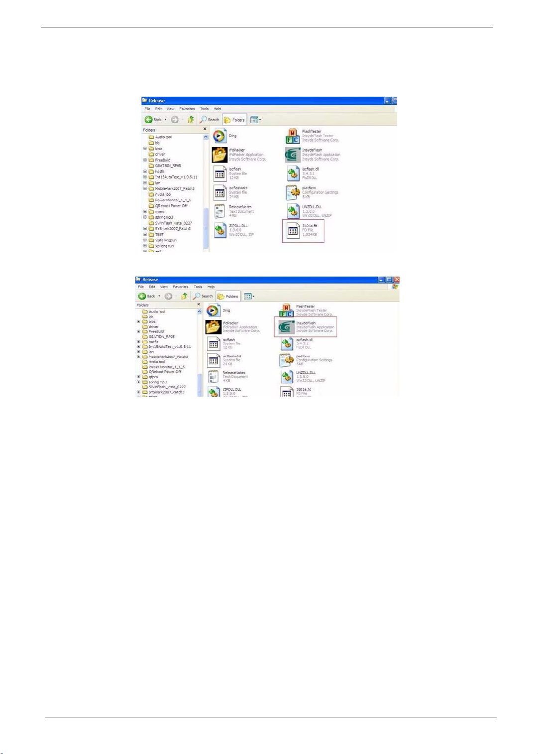
Perform the following steps to use the WinFlash Utility:
1. Copy the BIOS file into the Winflash folder.
2. Double-click the WinFlash executable file.
32 Chapter 2
Page 43

3. Click OK to begin the update. A progress screen displays.
4. When the process is complete, close all programs and applications and reboot the system.
Chapter 2 33
Page 44

Remove HDD/BIOS Password Utilities
To reset a hard drive or BIOS password you require an additional PC. The utilities run on a DOS prompt on the
second machine.
This section provides instructions on how to remove a HDD password. If you enter the wrong hard drive
password three times, the system reports the following error code:
To reset the HDD password, run HDD_PW.EXE on a second machine as follows:
1. At a command prompt, type hdd_pw 15494 0
2. Type 2.
3. Write down one of the two strings (in this example, OKJFN42 or UVEIQ96).
4. Reboot the system and type the selected string (in this example OKJFN42 or UVEIQ96) for the HDD user
password.
34 Chapter 2
Page 45

Removing BIOS Passwords:
If you key in the wrong Supervisor Password three times, System Disabled displays on the screen as below.
To reset the BIOS password, run BIOS_PW.EXE on a second machine as follows:
1. At a command prompt, type bios_pw 14452 0.
2. Select one string from the list.
Chapter 2 35
Page 46
3. Reboot the system and type the selected string (in this example qjjg9vy or 07yqmjd etc.) for the
BIOS user password.
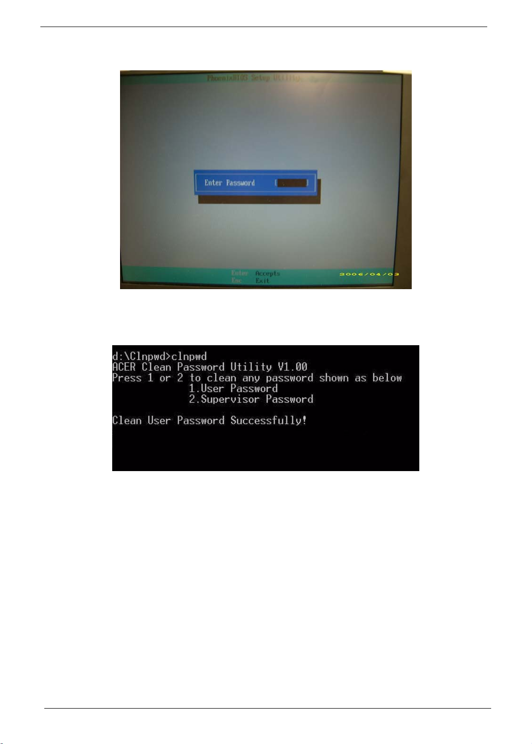
Cleaning BIOS Passwords
To clear the password, perform the following steps:
1. From a DOS prompt, Execute clnpwd.exe
2. Press 1 or 2 to clean the desired password shown on the screen.
The onscreen message determines whether the function is successful or not.
36 Chapter 2
Page 47
Miscellaneous Utilities
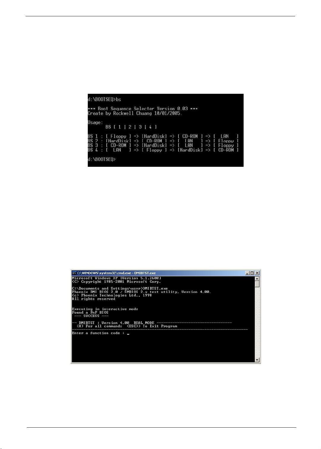
Using Boot Sequence Selector
Boot Sequence Selector allows the boot order to be changed without accessing the BIOS. To use Boot
Sequence Selector, perform the following steps:
1. Enter into DOS.
2. Execute BS.exe to display the usage screen.
3. Select the desired boot sequence by entering the corresponding sequence, for example, enter BS2 to
change the boot sequence to HDD|CD ROM|LAN|Floppy.
Using DMITools
The DMI (Desktop Management Interface) Tool copies BIOS information to eeprom to be used in the DMI pool
for hardware management.
When the BIOS displays Verifying DMI pool data it is checking the table correlates with the hardware before
sending to the operating system (Windows, etc.).
To update the DMI Pool, perform the following steps:
1. Op[en a command prompt.
2. Execute dmitools.exe. The following messages show dmitools usage:
IMPORTANT:The following write examples (2 to 5) require a system reboot to take effect
Chapter 2 37
Page 48

Example 1: Read DMI Information from Memory
Input:
dmitools /r
Output:
Manufacturer (Type1, Offset04h): Acer
Product Name (Type1, Offset05h): Aspire one xxxxx
Serial Number (Type1, Offset07h): 01234567890123456789
UUID String (Type1, Offset08h): xxxxxxxx-xxxx-xxxx-xxxx-xxxxxxxxxxxx
Asset Tag (Type3, Offset04h): Acer Asstag
Example 2: Write Product Name to EEPROM
Input:
dmitools /wp Acer
Example 3: Write Serial Number to EEPROM
Input:
dmitools /ws 01234567890123456789
Example 4: Write UUID to EEPROM
Input:
dmitools /wu
Example 5: Write Asset Tag to EEPROM
Input:
dmitools /wa Acer Asstag
Using the LAN MAC Utility
Perform the following steps to write MAC information to eeprom:
1. Use a text editor, for example Notepad, to edit the MAC.CFG file as shown:
• WriteData= '001122334455' <------- MAC value
• StartAddr=7A <------- MAC address
• WriteLeng=6 <------- MAC value length
• KeepByte=0 <------- can be any value
2. Boot into DOS.
3. Execute MAC.BAT to write MAC information to eeprom.
38 Chapter 2
Page 49

Machine Disassembly and Replacement
This chapter contains step-by-step procedures on how to disassemble the notebook computer for
maintenance and troubleshooting.
Disassembly Requirements
To disassemble the computer, you need the following tools:
• Wrist grounding strap and conductive mat for preventing electrostatic discharge
• Flat screwdriver
• Philips screwdriver
• Plastic flat screwdriver
• Plastic tweezers
NOTE: The screws for the different components vary in size. During the disassembly process, group the
screws with the corresponding components to avoid mismatch when putting back the components.
Chapter 3
Chapter 3 39
Page 50

General Information
Pre-disassembly Instructions
Before proceeding with the disassembly procedure, make sure that you do the following:
1. Turn off the power to the system and all peripherals.
2. Unplug the AC adapter and all power and signal cables from the system.
3. Place the system on a flat, stable surface.
4. Remove the battery pack.
Disassembly Process
The disassembly process is divided into the following stages:
• External module disassembly
• Main unit disassembly
• LCD module disassembly
The flowcharts provided in the succeeding disassembly sections illustrate the entire disassembly sequence.
Observe the order of the sequence to avoid damage to any of the hardware components. For example, if you
want to remove the main board, you must first remove the keyboard, then disassemble the inside assembly
frame in that order.
Main Screw List
Screw Quantity Part Number
M3*0.5+3.5I 2 86.A03V7.006
M2.5*3.0-I (BZN) 4 86.TPK07.003
M2.5*2-I (NI,NYLOK) IRON 3 86.EDM07.002
M2.5*4.0-I (BUWZN) (NYLON PATCH) IRON 10 86.EDM07.003
M2.5*5.0-I (BZN) 50 86.ARE07.003
M2.0*3.0-I (BKAG) (NYLOK) IRON 9 86.ARE07.002
40 Chapter 3
Page 51

External Module Disassembly Process
External Modules Disassembly Flowchart
Turn off system
and peripherals
power
Disconnect power
and signal cables
from system
Remove
RTC Battery
Remove
ODD
Remove
Battery
Remove
Lower Door
Remove
HDD
Remove
SD Dummy Card
Remove
DIMMs
Screw List
Step Screw Quantity Part No.
Lower Door M2.5*5 8 86.ARE07.003
ODD Module M2.5*5 1 86.ARE07.003
ODD Bracket M2*3 2 86.ARE07.002
HDD Carrier M3*3 2 86.A03V7.006
WLAN Module M2.5*4 2 86.EDM07.003
Remove
WLAN
Chapter 3 41
Page 52

Removing the Battery Pack
1. Turn the computer over.
2. Slide the battery lock to the unlocked position.
3. Slide and hold the battery release latch to the release position (1), then lift out the battery pack from the
main unit (2).
2
1
42 Chapter 3
Page 53

Removing the SD Dummy Card
1. Push the SD Dummy Card all the way in to eject it.
2. Pull the card out from the slot.
Chapter 3 43
Page 54

Removing the Lower Door
1. See “Removing the Battery Pack” on page 42.
2. Remove the eight screws securing the Lower Door to the Lower Cover.
Step Size Quantity Screw Type
Lower Door M2.5*5 8
3. Remove the Lower Door as shown.
44 Chapter 3
Page 55

Removing the RTC Battery
IMPORTANT: Follow local regulations for disposal of all batteries.
1. See “Removing the Lower Door” on page 44.
IMPORTANT: Do not pry the battery out of the socket. Using force may permanently damage the battery socket.
2. Slide the RTC Battery to the right to release the securing clips in the battery socket.
3. Lift the battery clear of the socket.
Chapter 3 45
Page 56

Removing the Optical Drive Module
1. See “Removing the Lower Door” on page 44.
2. Remove the single screw securing the ODD Module.
Step Size Quantity Screw Type
ODD Module M2.5*5 1
3. Insert a suitable object in to the Lower Cover to push the ODD Module clear of the casing.
4. Pull the ODD Module out of the chassis.
46 Chapter 3
Page 57

5. Remove the two screws securing the ODD Bracket and remove the ODD bracket from the module.
Step Size Quantity Screw Type
ODD Bracket M2*3 2
6. Insert a pin in the eject hole of the ODD to eject the ODD tray.
7. Press down on the locking catch to release the ODD cover and remove.
Chapter 3 47
Page 58

Removing the Hard Disk Drive Module
1. See “Removing the Lower Door” on page 44.
2. Use the pull-tab to slide the HDD in the indicated direction and disconnect the interface.
3. Lift the hard disk drive module out of the bay, right side first as shown.
NOTE: To prevent damage to device, avoid pressing down on it or placing heavy objects on top of it.
48 Chapter 3
Page 59

4. Remove the two screws securing the hard disk to the carrier.
Step Size Quantity Screw Type
HDD Carrier M3*3 2
5. Remove the HDD from the carrier.
Chapter 3 49
Page 60

Removing the DIMM Modules
1. See “Removing the Lower Door” on page 44.
2. Push out the release latches on both sides of the DIMM socket to release the DIMM module.
3. Remove the DIMM module.
4. Repeat steps for the second DIMM module.
50 Chapter 3
Page 61
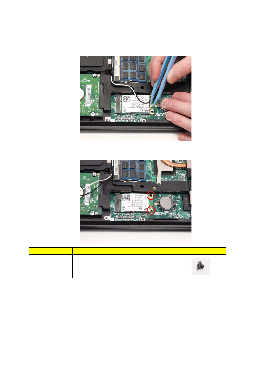
Removing the WLAN Module
1. See “Removing the Lower Door” on page 44.
2. Disconnect the Antenna cables from the WLAN Module.
NOTE: The black cable attaches to the MAIN terminal and the white cable attaches to the AUX terminal.
NOTE: When reattaching the antennas, ensure the cables are tucked into the chassis to prevent damage.
3. Remove the two screws securing the WLAN Module to the Mainboard
Step Size Quantity Screw Type
WLAN Module M2.5*4 2
Chapter 3 51
Page 62

4. Detach the WLAN Module from the WLAN socket.
52 Chapter 3
Page 63

Main Unit Disassembly Process
Main Unit Disassembly Flowchart
Remove External
Modules before
proceeding
Remove
TouchPad
Bracket
Upper
Cover
Remove
Switch Cover
Remove
Speaker Module
Remove
Microphone
Remove
Keyboard
Remove
LCD Module
Remove
Upper Cover
Remove
Bluetooth
Lower
Cover
Remove
Mainboard
Remove
USB Board
Remove
Hinge Supports
Screw List
Step Screw Quantity Part No.
Switch Cover M2.5*2 3 86.EDM07.002
M2.5*5 4 86.ARE07.003
LCD Module M2.5*5 6 86.ARE07.003
Upper Cover M2.5*5 18 86.ARE07.003
M2.5*4 4 86.EDM07.003
TouchPad Bracket M2.5*3 2 86.TPK07.003
Speaker Module M2.5*3 2 86.TPK07.003
Bluetooth Board M2*3 1 86.ARE07.002
USB Board M2.5*5 2 86.ARE07.003
Mainboard M2.5*5 1 86.ARE07.003
Hinge Supports M2.5*4 4 86.EDM07.003
Remove
Thermal Module
Remove
CPU
Chapter 3 53
Page 64

Removing the Switch Cover
1. See “Removing the Battery Pack” on page 42.
2. Remove the five screws securing the Switch Cover to the Upper Cover.
NOTE: The screws marked with green callouts are also marked on the Lower Cover with the letters KB.
Step Size Quantity Screw Type
Switch Cover
(red callout)
M2.5*2 3
Switch Cover
(green callout)
3. Remove the two screws on the spine of the Notebook securing the Switch Cover to the LCD Brackets.
Step Size Quantity Screw Type
Switch Cover M2.5*5 2
M2.5*5 2
54 Chapter 3
Page 65

4. Turn the computer over and open the LCD Panel to the full extent.
IMPORTANT: Do not use metal tools to remove the Switch Cover. Using metal tools may permanently damage the
casing.
5. Insert a suitable plastic tool in to the cutout located above the keypad Num Lock key, and pry the Switch
Cover away from the Upper Cover as shown.
6. Working from right to left, lift the Switch Cover away from the Upper Cover as shown.
7. Remove the Switch Cover from the Upper Cover.
Chapter 3 55
Page 66

Removing the Keyboard
1. See “Removing the Switch Cover” on page 54.
2. Lift the centre of Keyboard up as shown to release the four securing clips on the Upper Cover.
IMPORTANT: Do not remove the Keyboard from the computer; the Keyboard FFCs are still connected.
3. Turn the Keyboard over and place it on the TouchPad.
4. Disconnect the Keyboard cable by opening the FFC latch and removing the cable from the Mainboard.
5. Remove the Keyboard from the Upper Cover.
56 Chapter 3
Page 67

Removing the LCD Module
1. See “Removing the Keyboard” on page 56.
2. Turn the computer over. Remove the two screws securing the LCD Module to the Lower Cover.
Step Size Quantity Screw Type
LCD Module M2.5*5 2
3. Remove the Antenna cables from the cable channel. Ensure that the cables are free from all cable clips.
Chapter 3 57
Page 68

4. Pull the Antenna cables through the Upper Cover as shown. Ensure that the Antennas are completely
free from the cover.
5. Remove the Antenna from the cable channel all the way to the Hinge Well. Ensure that the cables are free
from all cable clips.
6. Grasp the pull tab and lift upward as shown to disconnect the LVDS cable.
58 Chapter 3
Page 69

7. Remove the LVDS cable from the cable channel all the way to the Hinge Well. Ensure that the cable is
free from the cable clip.
8. Remove the four screws securing the LCD Module to the Lower Cover.
Step Size Quantity Screw Type
LCD Module M2.5*5 4
9. Using both hands, lift the LCD Module clear of the Lower Cover.
Chapter 3 59
Page 70

Removing the Upper Cover
IMPORTANT: The TouchPad is supplied as part of the Upper Cover. If the TouchPad is defective, replace the entire
Upper Cover.
1. See “Removing the LCD Module” on page 57.
2. Turn the computer over. Remove the eighteen screws on the bottom panel.
Step Size Quantity Screw Type
Upper Cover M2.5*5 18
3. Turn the computer over and disconnect the following cables from the Mainboard.
A
B
NOTE: Avoid pulling on cables directly to prevent damage to the connectors.
NOTE: Use the pull-tabs on FFC cables whenever available to prevent damage.
C
60 Chapter 3
Page 71

4. Disconnect A as shown.
5. Disconnect B as shown.
6. Open the locking latch on C and disconnect the FFC from the Mainboard.
Chapter 3 61
Page 72

7. Remove the eleven screws securing the Upper Cover to the Lower Cover.
Step Size Quantity Screw Type
Upper Cover M2.5*4 4
8. Remove the Upper Cover, right side first as shown.
62 Chapter 3
Page 73

Removing the TouchPad Bracket
IMPORTANT: The TouchPad is supplied as part of the Upper Cover. If the TouchPad is defective, replace the entire
Upper Cover.
1. See “Removing the Upper Cover” on page 60.
2. Remove the two screws securing the bracket to the Upper Cover.
Step Size Quantity Screw Type
TouchPad
Bracket
M2.5*3 2
3. Lift the bracket right side first and remove it from the Upper Cover as shown.
Chapter 3 63
Page 74

4. Open the locking latch and remove the TouchPad FFC as shown.
5. Lift the protective sheet away from the Upper Cover to expose the TouchPad FFC as shown.
6. Peel the FFC away from the protective cover and remove the cable from the Upper Cover.
64 Chapter 3
Page 75

Removing the Speaker Module
1. See “Removing the Upper Cover” on page 60.
2. Lift the protective sheet away from the Upper Cover to expose the Microphone and Speaker cables as
shown.
3. Remove the Microphone cable from the first two cable clips as shown.
4. Remove the left speaker cable from the cable channel. Ensure that the cable is free from all cable clips.
Chapter 3 65
Page 76

5. Remove the right speaker cable from the cable channel. Ensure that the cable is free from all cable clips.
66 Chapter 3
Page 77

6. Turn the Upper Cover over and remove the speaker cable from the cable clip as shown.
7. Remove the two screws (one each side) securing the Speaker Modules to the Upper Cover.
Step Size Quantity Screw Type
Speaker Module M2.5*3 2
8. Remove the Speaker Modules from the Upper Cover as shown.
Chapter 3 67
Page 78

Removing the Microphone
1. See “Removing the Speaker Module” on page 65.
2. Remove the Microphone cable from the cable channel. Ensure that the cable is free from all cable clips.
3. Turn the Upper Cover over and remove the cable from the cable clip as shown.
4. Lift the Microphone clear of the Upper Cover.
68 Chapter 3
Page 79

Removing the Bluetooth Board
1. See “Removing the Upper Cover” on page 60.
2. Disconnect the Bluetooth cable from the Mainboard.
3. Disconnect the Bluetooth cable from the Bluetooth Board.
Chapter 3 69
Page 80

4. Remove the single screw securing the Bluetooth Board to the Lower Cover.
Step Size Quantity Screw Type
Bluetooth Board M2*3 1
5. Remove the Bluetooth Board from the Lower Cover.
70 Chapter 3
Page 81

Removing the USB Board
1. See “Removing the Upper Cover” on page 60.
2. Open the locking latch on the FFC and disconnect it from the Mainboard.
3. Open the locking latch on the FFC and disconnect it from the USB Board.
4. Remove the adhesive tape securing the USB FFC to the Lower Cover and remove the cable.
Chapter 3 71
Page 82

5. Remove the two screws securing the USB Board to the Lower Cover.
Step Size Quantity Screw Type
USB Board M2.5*5 2
6. Remove the USB Board from the Lower Cover as shown.
72 Chapter 3
Page 83

Removing the Mainboard
1. See “Removing the Hinge Supports” on page 75.
2. Turn the computer over. Disconnect the power cable from the Mainboard as shown.
3. Remove the single screw securing the Mainboard to the Lower Cover.
Step Size Quantity Screw Type
Mainboard M2.5*5 1
Chapter 3 73
Page 84

4. Rotate the Mainboard upward and remove it from the chassis, right side first. Place the Mainboard on a
clean, dust-free surface.
74 Chapter 3
Page 85

Removing the Hinge Supports
1. See “Removing the Mainboard” on page 73.
2. Remove the four screws (one on the left and three on the right) securing the Hinge Supports to the Lower
Cover.
Step Size Quantity Screw Type
Hinge Supports M2.5*4 4
3. Lift the Hinge Supports clear of the Lower Cover.
Chapter 3 75
Page 86

Removing the Thermal Module
1. See “Removing the Mainboard” on page 73.
2. Disconnect the fan cable from the Mainboard.
3. Loosen the six captive screws (in reverse numerical order from screw 6 to screw 1) securing the Thermal
Module in place.
5
6
4. Lift the Thermal Module clear of the Mainboard.
4
3
2
1
76 Chapter 3
Page 87

Removing the CPU
1. See “Removing the Thermal Module” on page 76.
2. Turn the securing screw 180° to release the CPU from the socket.
3. Remove the CPU from the socket as shown.
IMPORTANT: The pins on the underside of the CPU are very delicate. If they are damaged, the CPU may
malfunction. Place the CPU on a clean, dry surface when it is not installed.
Chapter 3 77
Page 88

LCD Module Disassembly Process
IMPORTANT:Cable paths and positioning may not represent the actual model. During the removal and
replacement of components, ensure all available cable channels and clips are used and that the
cables are replaced in the same position.
LCD Module Disassembly Flowchart
Remove LCD
Panel from Main
Unit before
proceeding
Remove
LCD Bezel
Remove
LCD Panel
Remove
LCD FPC Cable
Remove
LCD Brackets
Remove
Camera Module
Screw List
Step Screw Quantity Part No.
LCD Bezel M2.5*5 6 86.ARE07.003
LCD Panel M2.5*5 4 86.ARE07.003
LCD Brackets M2*3 6 86.ARE07.002
78 Chapter 3
Page 89

Removing the LCD Bezel
1. See “Removing the LCD Module” on page 57.
2. Remove the six screw caps and screws from the LCD Bezel.
Step Size Quantity Screw Type
LCD Bezel M2.5*5 6
3. Starting from the inside bottom edge, pry the Bezel away from the panel. Continue up the sides as shown.
If necessary, use a plastic pry to release the corners of the Bezel.
Chapter 3 79
Page 90

4. Lift up the Bezel and remove it from the LCD Module.
80 Chapter 3
Page 91

Removing the LCD Panel
1. See “Removing the LCD Bezel” on page 79.
2. Remove the four securing screws from the LCD Panel.
Step Size Quantity Screw Type
LCD Panel M2.5*5 4
3. Lift the LCD Panel, front edge first, and turn it over to expose the Camera cable.
Chapter 3 81
Page 92

4. Disconnect the Camera cable and remove the LCD Panel.
82 Chapter 3
Page 93

Removing the FPC Cable and LCD Brackets
1. See “Removing the LCD Panel” on page 81.
2. Lift the cable away from the LCD Panel to detach the adhesive securing it in place.
3. Carefully lift the adhesive tape securing the cable to the panel.
Chapter 3 83
Page 94

4. Disconnect the cable from the LCD panel as shown.
5. Remove the six securing screws (three each side) from the LCD Panel brackets.
Step Size Quantity Screw Type
LCD Brackets M2*3 6
6. Remove the brackets from the LCD Panel.
84 Chapter 3
Page 95

Removing the Camera Board
1. See “Removing the LCD Panel” on page 81.
2. Remove the Camera Board from the LCD Module.
Chapter 3 85
Page 96

LCD Module Reassembly Procedure
Replacing the Camera Board
1. Ensure that the locating pins are correctly positioned and place the Camera Board in the LCD Module.
2. Press down to secure it in place
86 Chapter 3
Page 97

Replacing the LCD Brackets and FPC Cable
1. Secure the brackets to the panel using six bracket screws (three each side).
2. Insert the LCD Cable into the panel connector
as shown.
4. Replace the LCD cable as shown. Press down as indicated to secure the cable in place.
3. Secure the connector by replacing the adhesive
strip as shown.
Chapter 3 87
Page 98

IMPORTANT:Ensure that the LCD Cable runs as shown to avoid trapping when the Bezel is replaced.
88 Chapter 3
Page 99

Replacing the LCD Panel
1. Place the LCD Panel adjacent to the LCD Cover and reconnect the Camera cable.
2. Turn the panel over and place it in the LCD Cover.
IMPORTANT: Ensure that the cables are not trapped under the panel.
3. Replace the four screws to secure the panel in place.
Step Size Quantity Screw Type
LCD Panel M2.5*5 4
Chapter 3 89
Page 100

Replacing the LCD Bezel
1. Place the Bezel onto the LCD Module ensuring that the cables exit the module as shown and are not
trapped between the bezel and the cover.
2. Press down around the perimeter of the Bezel to snap it in to place.
3. Replace the six screws and screw caps for the LCD Bezel.
Step Size Quantity Screw Type
LCD Bezel M2.5*5 6
90 Chapter 3
 Loading...