

Page 1

Extensa 500 Notebook
Service Guide
Service Guide files and updates are available on Acer
Intranet and CSD database on Lotus Notes.
For more detailed information, please refer to
Service CD kit.
Page 2

Copyright
Copyright * 1996 by Acer Incorporated. All rights reserved. No part of this
publication m ay be reproduced, transmitted, transcribed, stored in a retri eval
system, or translated into any language o r computer language, in any form or
by any means , ele ctroni c, mech ani cal, magnet ic, optic al, c hemical , ma nual or
otherwise, with out the prior written per mission of Acer Incorpor ated.
Disclaimer
Acer Incorporated makes no representations or warranties, either expressed
or implied, with respect to the contents hereof and specifically disclaims any
warranties of merchantability or fitness for any particular purpose. Any Acer
Incorporat ed software described i n thi s ma nual is sold or licensed "as is" .
Should the progr ams prove def ect ive f ollowing t hei r purcha se, the bu yer (and
not Acer Incorporated, its distributor, or its dealer) assumes the entire cost of
all necessary servicing, repair, and any incidental or consequential damages
resultin g from any defect in t he softwar e. F urther, Acer I ncorpor at ed rese rve s
the right to revise this publicati on and to make changes from time to time in
the contents hereof without obligation of Acer Incorporated to notify any
person of such revision or changes.
Acer is a registered trademark of Acer Incorporated.
Intel is a regist ered trademark of Intel Corporation.
Pentium is a trademar k of Intel Corporation.
Other brand and product names are trademarks and/or registered
trademarks of th eir respective holders.
Page 3

PART No: 49.42B02.001....................................................PRINT IN TAIWAN
DOC No: SG281-9807A
Page 4

Chapter 1 System Introduction
Basic Operation . . . . . . . . . . . . . . . . . . . . . . . . . . . 11
Indicators . . . . . . . . . . . . . . . . . . . . . . . . . . . . 11
Keyboard . . . . . . . . . . . . . . . . . . . . . . . . . . . . . . . . 12
Special Keys. . . . . . . . . . . . . . . . . . . . . . . . . . 12
Hardware Configuration and Specification. . . . . . . 17
Memory Address Map . . . . . . . . . . . . . . . . . . 17
Interrupt Channel Assignment . . . . . . . . . . . . 17
DMA Channel Assignment . . . . . . . . . . . . . . . 18
I/O Address Map. . . . . . . . . . . . . . . . . . . . . . . 18
Processor. . . . . . . . . . . . . . . . . . . . . . . . . . . . 19
BIOS. . . . . . . . . . . . . . . . . . . . . . . . . . . . . . . . 19
System Memory . . . . . . . . . . . . . . . . . . . . . . . 20
DIMM Combinations. . . . . . . . . . . . . . . . . . . . 20
Video Memory . . . . . . . . . . . . . . . . . . . . . . . . 21
Cache Memory . . . . . . . . . . . . . . . . . . . . . . . . 2 1
Video . . . . . . . . . . . . . . . . . . . . . . . . . . . . . . . 2 1
Video Resolutions Modes. . . . . . . . . . . . . . . . 21
Parallel Port . . . . . . . . . . . . . . . . . . . . . . . . . . 2 2
Serial Port . . . . . . . . . . . . . . . . . . . . . . . . . . . . 22
Audio . . . . . . . . . . . . . . . . . . . . . . . . . . . . . . . 2 3
PCMCIA . . . . . . . . . . . . . . . . . . . . . . . . . . . . . 23
Modem . . . . . . . . . . . . . . . . . . . . . . . . . . . . . . 23
Keyboard . . . . . . . . . . . . . . . . . . . . . . . . . . . . 24
Diskette Drive. . . . . . . . . . . . . . . . . . . . . . . . . 24
Hard Disk Drive . . . . . . . . . . . . . . . . . . . . . . . 24
CD-ROM. . . . . . . . . . . . . . . . . . . . . . . . . . . . . 25
Battery Pack. . . . . . . . . . . . . . . . . . . . . . . . . . 26
DC-DC/Charger Board . . . . . . . . . . . . . . . . . . 26
LCD Inverter. . . . . . . . . . . . . . . . . . . . . . . . . . 27
LCD . . . . . . . . . . . . . . . . . . . . . . . . . . . . . . . . 27
Power Adapter . . . . . . . . . . . . . . . . . . . . . . . . 28
Power Management. . . . . . . . . . . . . . . . . . . . . . . . 30
Power Management Modes . . . . . . . . . . . . . . 30
BIOS Setup Utility. . . . . . . . . . . . . . . . . . . . . . . . . . 33
Table of Content s
Chapter 2 Software Utilities
Basic System Settings . . . . . . . . . . . . . . . . . . 34
4 Table of Contents
Page 5

Table of Contents
Startup Configuration. . . . . . . . . . . . . . . . . . . .35
Onboard Devices Configuration . . . . . . . . . . .36
System Security. . . . . . . . . . . . . . . . . . . . . . . .37
Power Management . . . . . . . . . . . . . . . . . . . .39
Load Default Settings . . . . . . . . . . . . . . . . . . .40
AFlash Ut ilit y . . . . . . . . . . . . . . . . . . . . . . . . . . . . . .41
Executing AFlash. . . . . . . . . . . . . . . . . . . . . . .41
Quick Way to Execute AFlash. . . . . . . . . . . . .42
System Utility Diskette. . . . . . . . . . . . . . . . . . . . . . .43
Set LCD Panel ID . . . . . . . . . . . . . . . . . . . . . .43
Set Thermal Sensor Threshold . . . . . . . . . . . .43
System Diagnostic Diskette. . . . . . . . . . . . . . . . . . .44
Running PQA Diagnostics Program. . . . . . . . .45
Diagnostic Program Error Code and Messages47
Chapter 3 Machine Disassembly
General Information. . . . . . . . . . . . . . . . . . . . . . . . .50
Before You Begin . . . . . . . . . . . . . . . . . . . . . .50
Connector Types . . . . . . . . . . . . . . . . . . . . . . .50
Disassembly Procedure Flowchart . . . . . . . . . . . . .51
Removing the Battery Pack . . . . . . . . . . . . . . .53
Removing the DIMM . . . . . . . . . . . . . . . . . . . .53
Removing the Modem Board. . . . . . . . . . . . . .54
Removing the Keyboard . . . . . . . . . . . . . . . . .55
Removing the LCD Module . . . . . . . . . . . . . . . . . . .57
Disassembling the LCD. . . . . . . . . . . . . . . . . .58
Disassembling the Main Unit. . . . . . . . . . . . . . . . . .61
Removing the HDD & PCMCIA Heat Sink. . . .61
Remo ving the Hard Disk Drive . . . . . . . . . . . . 6 1
Removing the CPU Heat Sink and CPU Board62
Removing the RTC Battery . . . . . . . . . . . . . . .63
Disassembling the Upper Case. . . . . . . . . . . .63
Removing the Touchpad . . . . . . . . . . . . . . . . .64
Disassembling the Lower Case. . . . . . . . . . . . . . . .66
Removing the CD-ROM/Diskette Drive Module66
Removing the Speakers . . . . . . . . . . . . . . . . .68
Removing the DC-DC/Charger Board . . . . . . .69
Removing the DC-DC/Charger Board . . . . . . .70
Removing the System Board. . . . . . . . . . . . . .70
Extensa 500 Service Guide 5
Page 6

Removing the PCMCIA slot . . . . . . . . . . . . . . 71
Removing the Modem Phone Jack. . . . . . . . . 71
Chapter 4 Tro ub lesh oo tin g
System Check Procedures. . . . . . . . . . . . . . . . . . . 74
Diskette Drive Check . . . . . . . . . . . . . . . . . . . 7 4
CD-ROM Drive Check . . . . . . . . . . . . . . . . . . 74
Keyboard or Auxiliary Input Device Check . . . 75
Memory Check. . . . . . . . . . . . . . . . . . . . . . . . 75
Power System Check. . . . . . . . . . . . . . . . . . . 7 5
Touchpad Check . . . . . . . . . . . . . . . . . . . . . . 77
Error Symptom-to-FRU Index. . . . . . . . . . . . . . . . . 78
Error Messages List . . . . . . . . . . . . . . . . . . . . 78
No-Beep Symptoms . . . . . . . . . . . . . . . . . . . . 80
LCD-Related Symptoms . . . . . . . . . . . . . . . . . 81
Indicator- Rela ted Sympto m s . . . . . . . . . . . . . 82
Power-Related Symptoms . . . . . . . . . . . . . . . 82
PCMCIA-Related Symptoms . . . . . . . . . . . . . 83
Memory-Related Symptoms. . . . . . . . . . . . . . 83
Speaker-Related Symptoms . . . . . . . . . . . . . . 83
Power Management-Related Symptoms . . . . 8 4
Peripheral-Related Symptoms . . . . . . . . . . . . 85
Keyboard/Touchpad-Related Symptom s . . . . 85
Intermittent Problems . . . . . . . . . . . . . . . . . . . 86
Undetermined Problems. . . . . . . . . . . . . . . . . 8 6
Modem-Related Symptoms . . . . . . . . . . . . . . 86
Chapter 5 Connectors and Jumpers
SW1 Settings . . . . . . . . . . . . . . . . . . . . . . . . . 90
SW2 Settings . . . . . . . . . . . . . . . . . . . . . . . . . 90
Spare Parts List (P/N:91.45BXX.XXX). . . . . . 91
Chapter 6 Spare Parts List
Model Number Definitions . . . . . . . . . . . . . . 101
6 Table of Contents
Page 7

Appendix AModel Definitions
Appendix BCompatibility Tested Components
Extensa 500 Service Guide 7
Page 8

8 Table of Contents
Page 9

Chapter 1
System Introduction
This computer was designed with the user in mind. Here are just a few of its
many features:
Performance
❑
Intel Pentium® pro cessor with MMX™ technology
❑
512-KB, 64-bit main m em ory and external (L2) cache memor y
❑
Large LCD display and PCI local bus video with 128-bit graphics
acceleration
❑
Internal CD-ROM drive
❑
Internal 3.5-inch floppy drive
❑
High-capacity, Enhanced-IDE removable hard disk
❑
Nickel metal-hydride battery pack
❑
Heuristic power managem ent system with standby and hibernation
power saving modes
Multimedia
❑
ISA-based 16- bit h igh-f ideli ty s tereo audi o wit h 3-D so und and wa vetabl e
synthesizer
❑
Built-in dual speakers
❑
“No power-on” audi o CD playback
❑
Ultra-slim, high-speed CD-ROM drive
Connectivity
❑
High-speed fax/ data modem port
❑
USB (Universal Serial Bus) port
Human-centric Design and Ergonomics
❑
Lightweight and slim
❑
Sleek, smooth and st ylish design
❑
Full-sized keyboard
❑
Wide and curved palm rest
❑
Ergonomically-centered touchpad pointing device
Expansion
❑
CardBus PC card (formerly PCMCIA) slots (two type II/I or one type III),
upper sort with additional ZV (Zoomed Video) port support.
❑
Mini docking st ation option for one-step connection to/disconnection
Chapter 1
9
Page 10

from peripher als
❑
Upgradeable memory and hard disk
Display
The large graphics display offers excellent viewing, excellent display quality
and high performance desktop graphics. The computer supports two
differ ent display configurations — High Performance Addressing (HPA) or
Thin-Film Transistor (TFT).
Video Perform ance
The PCI local bus video with 128-bit graphics acceleration and 2MB
Extended Data Out (EDO) vi deo RAM boosts video performance.
Simultaneous Display
The computer’s large display and multimedia capabilities are great for giving
presentati ons. If you prefer , you can also connect an external monitor when
giving presentations. This computer supports simultaneous LCD and CRT
display. Simultaneous display allows you to control the presentation from
your computer and at the same time face your audience. You can also
connect other out put display devi ce s such as LCD projection panels for l argeaudience presentations.
Power Management
The power management system incorporates an “automatic LCD dim”
feature tha t automat ical ly deci des the be st settings f or your di splay and at the
same time conserves power. See “Power Management Modes” on page 30
for more informa tion on power management features.
Opening and Closing the Display
To open the displ ay, slide the display cover latch to the left and lif t up t he
cover . Then til t it to a comfortab le viewing posi t ion. The comput er employ s a
microcircuit that turns off the display (and enters standby mode) to conserve
power when you close the display cover, and turns it back on when you o pen
the display cover.
Note:
If an external monitor is connected, the compu ter turns off the
display (but does not ent er standby mode) when you close the
display cover.
To close the display cover, fold it down gently unti l the display cover latch
clicks int o place.
10
System Introduc tion
Page 11
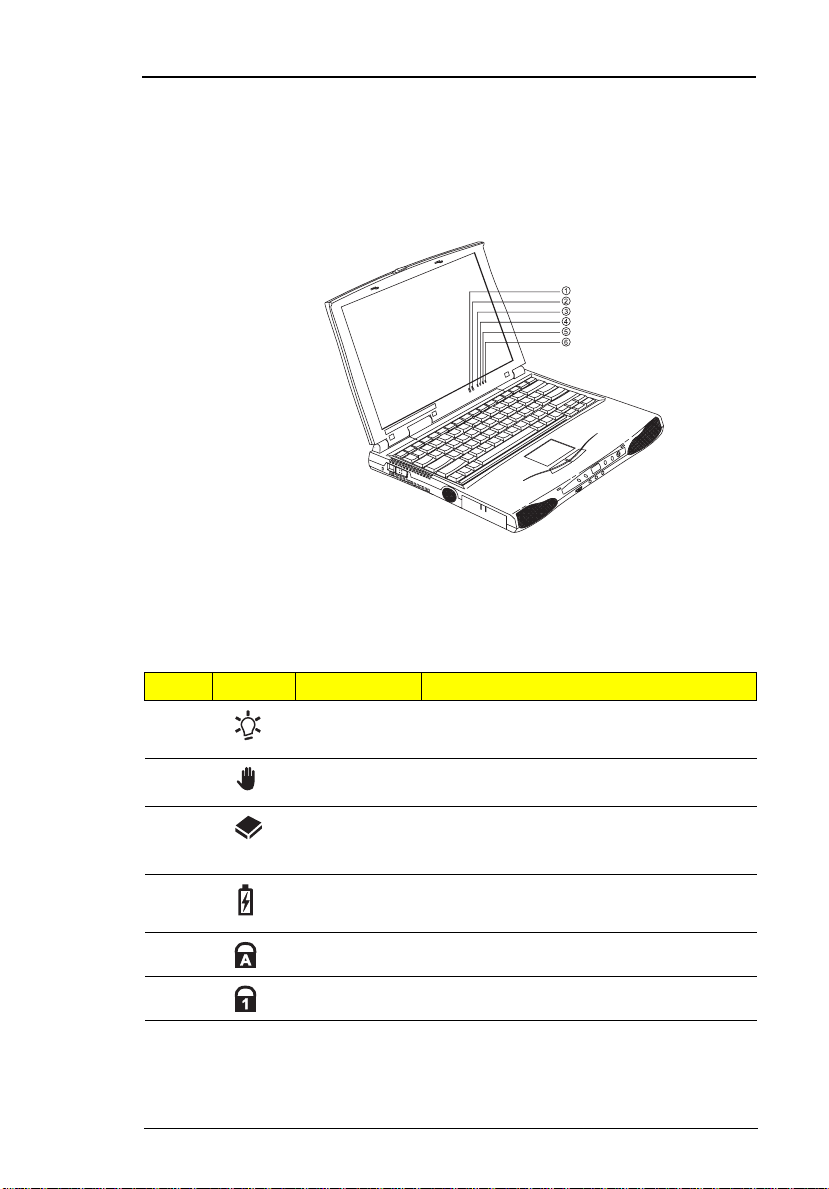
Basic Oper ati on
Indicators
The computer has si x easy- t o-read status indi cat ors ( LEDs) under the d is play
screen.
The Power and Standby indi cators are visible even when you close the
display cover so you can see the status of the computer while the cover is
closed.
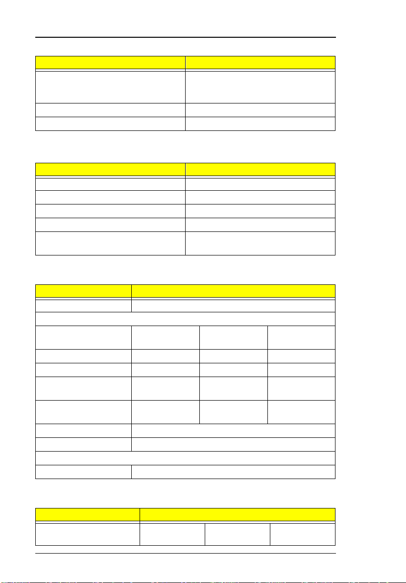
# Icon Function Description
1 Power Lights when the c omputer i s on.
Blinks when a battery-low condition occurs.
2 Standby Light s when the computer enters Standby
3Media
Activity
4 Battery
Charge
5 Caps Lock Lights when Caps Lock is activated
6 Num Lock Lights when Numeric Lock is activated
mode.
Lights when the floppy dri ve, hard disk or
CD-ROM drive (or other media bay
module) is active.
Lights when the battery is being charged.
Chapter 1
11
Page 12
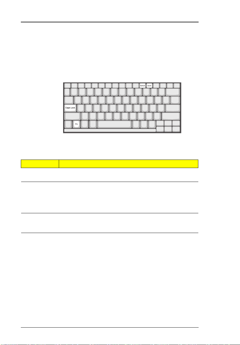
Keyboard
The keyboard has full-siz ed keys and an embedded keypad, separ ate cursor
keys, two Windows 98 keys and twelve function keys.
Special Keys
Lock Keys
The keyboard has three lock keys which you can toggle on and off.
Lock Key Description
Caps Lock When Caps Lock is on, all alphabetic characters typed are in
Num Lock
(Fn-F1 1)
Scroll Lock
(Fn-F12)
uppercase.
When Num Lock is on, the embedded keypad is in numeric
mode. The keys function as a calculator (complete with the
arithmetic oper ators +, -, *, and /). Use th is mode whe n you
need to do a lot of numeric data entry. A better solution would
be to conn ect an ex ternal keypad.
When Scroll Lock i s on, the scr een moves one line up or down
when you pr ess ↑ or ↓ re spectively. Scroll Lock does not work
with some applications.
12
System Introduc tion
Page 13
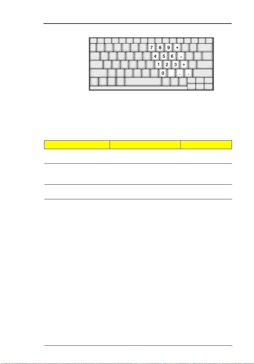
Embedded Numeric Keypad
The embedded numeric keypad functions like a desktop numeric keypad. It
is indicated by sm all characters locate d on the upper right corner of the
keycaps. To simplify the key boar d lege nd, cursor -c ontrol key symbol s are not
printed on the keys.
Desired Access Num Lock On Num Lock Off
Number keys on
embedded keypad
Cursor-control keys on
embedded keypad
Main keyboard keys Hold Fn while typing letters
Type numbers in a norma l
manner.
Hold Shift while using
cursor-control keys.
on embedded keypad.
Hold Fn while
using cursorcontrol keys.
Type the letters in
a normal manner.
Note:
Chapter 1
If an external keyboard or keypad is connected to the computer,
the numlock feature automatically shifts from the internal
keyboard to the external keyboard or keypad.
13
Page 14
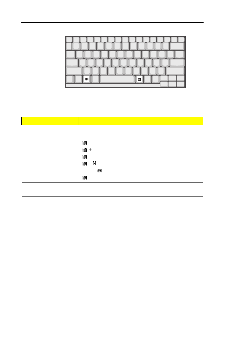
Windows 98 Keys
The keyboard has tw o keys that perform Windo ws 98-specific funct ions.
Key Description
Windows logo key Start button. Combinations with this key performs
special functions. Below are a few examples:
+ Tab (Activate next Taskbar button)
+ E (Explore My Computer)
+ F (Find D ocument)
+ M (Minimize All)
Shift + + M (Undo Mi nimize Al l)
+ R (Display Run dialog box)
Application key Opens the applic ation’s context menu (same as right-
click).
14
System Introduc tion
Page 15
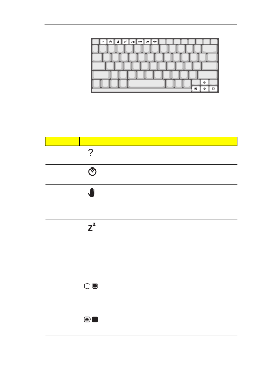
Hot Keys
The computer empl oys hot keys or key combinat ions to access most of the
computer’s controls like screen co ntrast and brightness, volume output and
the BIOS setup utility .
Hot Key Icon Function Description
Fn-F1 Hot key help Displays a list of the hotkeys and
their functions.
Fn-F2 Setup Accesses the notebook
configuration utility. .
Fn-F3 Standby Puts the computer in Standby
mode. Press any ke y to ret u rn.
See “System Standby Mode” on
page 30 t o learn more about
Standby mode .
Fn-F4 Hibernation Puts the computer in Hibernation
Fn-F5 Display toggle Switches display output between
Fn-F6 Screen blank Turns the display scree n backlight
mode (if Sleep Manager, the
hiberna tio n util ity, is install ed, valid
and enabled). Press the power
switch to resume.
Other wise, th e computer enters
Standby mode. See “Hibernation
Mode” on page 31 for more about
Hibernation mode.
the display screen, external
monit or (if connect e d) and both
the display screen and external
monitor.
off to save power. Press any key
to return.
Chapter 1
15
Page 16
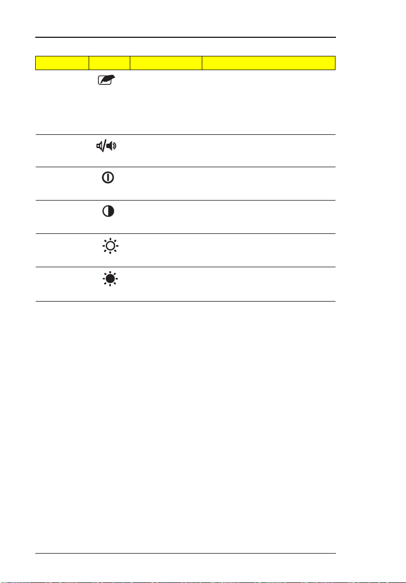
Hot Key Icon Function Description
Fn-F7 Touchpad on/off Turns the internal touchpad on
and of f.
When you connect an external
PS/2 mouse, the computer
automatically disables the
touchpad.
Fn-F8 Speaker on/off Turns the speakers on and off;
mutes the sound.
Fn-↑ Contrast up Increases the screen contrast
Fn-↓ Contrast down Decreases the screen contrast
Fn-→ Brightness up Increases the screen brightness.
Fn-
←
Brightness
down
(available only for models with
HPA displays).
(available only for models with
HPA displays).
Decreases the screen brightness .
16
System Introduc tion
Page 17
Hardware Configuration and Specification
Memory Address Map
Memory Address Size Function
00000000-0009FFFF 640 KB Base memory
000A0000-000BFFFF 128 KB Video memory
000C0000-000C9FFF 40 KB Video BIOS
000CA000-000CBFFF 8 KB I/O ROM
000E0000-000FFFFF 128 KB System BIOS
001000 00 - to p lim i t ed
04301000-043 01FFF
04302000-043 02FFF
0430000-04300FFFF
FFFF0000-FFFFFFFF 64 KB System board extension for
Interrupt Channe l Assi gnm ent
Interrupt Channe l Function
NMI System errors
IRQ0 System timer
IRQ1 Keyboard
IRQ2 Cascade
IRQ3 Modem or Audio (optio nal)
IRQ4 COM1 or Modem (optional)
IRQ5 Audio or LPT2 (opt ional)
IRQ6 Floppy
IRQ7 LPT1 or Audio (opt ional) or Modem (optional )
IRQ8 Real time clock
IRQ9 Card bus / ACPI or Audio (optio nal)
IRQ10 USB or Audio (optional) or Modem (optional)
IRQ11 Audio (optional) or Modem (op tional)
IRQ12 PS2 pointing de vi ce
IRQ13 Numeric data processor
IRQ14 1st EIDE device (hard disk)
IRQ15 2nd EIDE device (CD-ROM drive)
- 4 KB
4 KB
64 KB
Extended (DIMM) memory
PCMCIA controller (slot 1)
PCMCIA controller (slot 2)
USB controller
PnP BIOS
Chapter 1
17
Page 18
DMA Channel Assignment
DMA Channel Function
DRQ0 Audio(optio nal)
DRQ1 ECP or Audio(optional)
DRQ2 Floppy
DRQ3 ECP(optional)
DRQ4 DMA controller
DRQ5 Not used
DRQ6 Not used
DRQ7 Audio
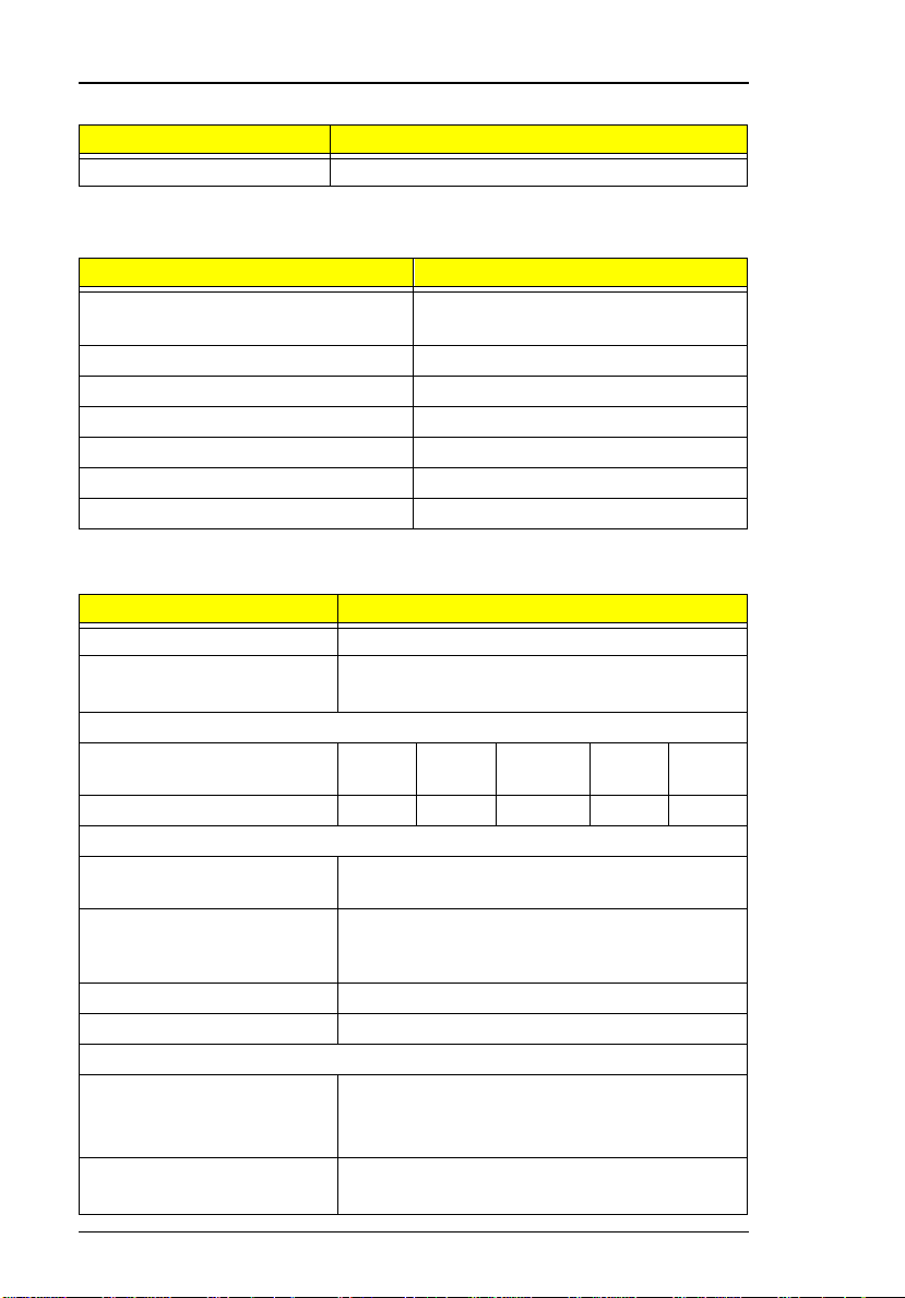
I/O Address Map
I/O Address Function
000-00F DMA controll er-1
020-021 Interrupt controller-1
040-043 Timer 1
060, 064 Keyboard controller 8742 chip select
061 System speaker out
040B DMA controller-1
061 System speaker
070-071 Real-time clock and NMI mask
080-08F DMA page register
0A0-0A1 Interrupt controller-2
0C0-0DF DMA controll er-2
0F0-0FF Numeric data processor
120-13F
180-18F
170-177 2nd EIDE devi ce (CD-ROM) select
1F0-1F7 1st EIDE device (hard drive) select
220-22F Audio
240-24F Audio(optional)
278-27F Parallel port 3
2E8-2EF LT Win modem or COM4(optional)
2F8-2FF COM2 or LT Win modem(optional)
378, 37A Parallel port 2
Power management contr oller
18
System Introduc tion
Page 19
I/O Address Map
I/O Address Function
3BC-3BE paraller port 1
3B0-3B B
3C0-3D F
3F0h-3F7 Standard Floppy Disk Controller
3E8-3EF COM3 or LT Win modem(optional)
3F0-3F7 Floppy disk controller
3F8-3FF COM1 or LT Win modem(optional)
480-48F, 4D6 DMA controller-1
4D0-4D1
CF8-CFF
Video Controller
PCI configuration register
Processor
Item Specification
CPU type Intel T illamook 233/266 Mhz processor
CPU package TCP package
CPU core voltage 1.8V
CPU I/O voltage 2.5V
Tillamook--Intel Pentium architecture, 64 bit data bus,
16K-Byte code cache, 16 K-Bytes write back data,
cache, with MMX technology
BIOS
Item Specification
BIOS ve nd or Acer
BIOS Version V 3.0
BIOS ROM type Flash ROM
BIOS RO M si ze 256KB
BIOS pa ck a ge 32-pin TS O P
Supports protocol PCI 2.1, APM 1.2, DMI 2.00.1, E-IDE, ACPI, USB,
ESCD 1.03, ANSI ATA 3.0, PnP 1.0a, Bootable CDROM 1.0, ATAPI, LDCM 3.3
BIOS password control Set by switch, see SW2(swtich 2) settings
Chapter 1
19
Page 20

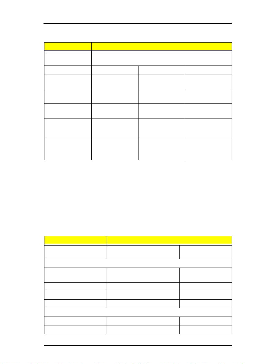
System Memory
Item Specification
Memory controller ALi M1531
Onboard memory size 0MB
DIMM socket number 2 sockets (2 banks)
Supports memory size per socket 16/32/64/128 MB
Supports maximum memory size 256MB (128MB x 2)
Supports DIMM type Sync hronous DRAM
Supports DIMM Speed 100MHz
Supports DIMM voltage 3.3V
Supports DIMM package 144-pin DIMM
DIMM Combinations
Slot 1 Slot 2 Total Memory
0 16MB 16MB
0 32MB 32MB
0 64MB 64MB
0 128M B 128MB
16MB 16MB 32MB
16MB 32MB 48MB
16MB 64MB 80MB
16MB 128MB 144M B
32MB 16MB 48MB
32MB 32MB 64MB
32MB 64MB 96MB
32MB 128MB 160M B
64MB 16MB 80MB
64MB 32MB 96MB
64MB 64MB 128MB
64MB 128MB 192M B
128MB 16M B 144MB
128MB 32M B 160MB
128MB 64M B 192MB
128MB 128M B 256MB
20
System Introduc tion
Page 21
Video Memory
Item Specification
Fixed or upgradeable Fixed, built-in NM2097B video
controller
Video memory size 2MB
Cache Memory
Item Specification
Cache controller ALi M1531
Tag RAM l ocation U32
Tag RAM size 32 KB
Tag RAM voltage 3.3V
SRAM type PBSRAM
SRAM size 512 KB
SRAM location U37
SRAM co nfigura tion 64K*64 x1
SRAM speed Cycle time = 7ns
SRAM voltage 3.3V
1st level cache control Always enabled
2st level cache control Always enabled
Cache scheme cont rol Fixed in write-back
Video
Item Specification
Chip vendor N e oM a gic
Chip name NM2097B
Chip v oltage 3.3 Volts
Supports ZV((Zoo med Video) port Yes
Graph interface (ISA/VESA /PCI) PCI bus
Maximun resolution (LCD) 1024x768 (256 colors)
Maximnun resolution (CRT) 1024x768 (256 colors)
Video Resoluti ons M odes
Resolution Refresh Rate
CRT Only LCD/CRT Simultaneous
Chapter 1
21
Page 22
Video Resoluti ons M odes
Resolution Refresh Rate
640x48 0x256 85 60
640x48 0x64K 85 60
640x48 0x16M 85 60
800x60 0x256 85 60
800X600X64K 85 60
1024x768x256 60, 75 60
Parallel Port
Item Specification
Parallel port controller NS PC97338VJG
Number of parallel ports 1
Locati on Rear side
Connector type 25-pi n D-type connector, in female
type.
Parallel port function control Enable/Diable by BIOS Setup
Supports ECP Yes (set by BIOS setup)
Optional ECP DMA channel
(in BIOS Setup)
Optional parallel port I/O address
(in BIOS Setup)
Optional parallel port IRQ
(in BIOS Setup)
DMA ch an ne l 1
DMA Channel 3
3BCh, 378h, 278h
IRQ5, IRQ7
Serial Port
Item Specification
Serial port controller NS PC97338VJG
Number of serial ports 1
Supports 16550 UART Yes
Connector type 9-pin D-type connector, in male typ e
Location Rear side
Serial port function control Enable/disable by BIOS Setup
Optional serial port
(in BIOS Setup)
Optional serial port IRQ
(in BIOS Setup)
22
3F8h, 2F8h, 3E8 h, 2E8h, Disabled
IRQ4, IRQ11
System Introduc tion
Page 23
Audio
Item Specification
Audio Controller Yamaha YMF715E
Audio onboard or optional Built-in
Mono or Stereo Stereo
Resolution 16-bi t
Compatibility SB-Pro, Windows Sound System
Mixed so und source Voice, Synthesizer, Line-in,
Voice channel 8-/16-bit, mono/stereo
Sampling rate 44.1 KHz
Internal microphone Yes, on the left-higher corner of LCD
Internal speaker / Qua ntity Yes / 2 pieces, on both hinge sides
Supports PnP DMA channel DMA channel 0
Supports PnP IRQ IRQ3, IRQ5, IRQ7, IRQ9, IRQ10,
(WSS), MPU-401, OPL3, OPL3-SA3
Microphone, CD
panel
DMA ch an ne l 1
DMA ch an ne l 7
IRQ11
PCMCIA
Item Specification
PCMCIA controller O2 OZ6833T
Supports card type Ty pe-II / type-III
Number of slots Two type-II or one type-III
Access location Right side
Supports ZV (Zoomed Video) port Yes (for upper slot)
Supports 32 bit CardBus Yes (IRQ9, for both slots)
Modem
Item Specification
Chipset Luce nt 16 41 B
Fax modem data baud rate (bps) 56K
Data modem data baud rate (bps) 56K
Chapter 1
23
Page 24
Modem
Item Specificat ion
Supports modem protocol V.90 data modem, V.90 fax modem,
audio mode, and digital line protection
operation
Modem connector type RJ11
Modem co nnector location Right si de
Keyboard
Item Specification
Keyboard controller Mitsubishi M38867
Keyboard vendor & model name AP I
Total number of keypads 84-/85- /89-key
Windows 95 keys Yes
Internal & external keyboard work
simultaneously
Yes
Diskette Drive
Item Specification
Vendor & model name Misumi D353F3
Floppy Disk Specifications
Media recognition 2DD (720KB) 2HD (1.2MB,
3-mode)
Sectors / track 9 15 18
Tracks 80 80 80
Data transfer rate (Kbit/s)250 ~ 300 500 500
2HD (1.44MB)
Rotational speed
(RPM)
Read/write heads 2
Encoding method MFM
Power Requirement
Input Voltage (V) +5 +-10%
300 ~ 360 360 300
Hard Disk Drive
Item Specification
Vendor & Model Name Hitachi
DK226A-32u
24
IBM DTCA23240
IBM DKLA24320
System Introduc tion
Page 25
Hard Disk Drive
Item Specification
Drive Format
Capacity (MB) 3240 3240 4320
Bytes per sector 512 512 512
Logica l he ads 16 16 1 5
Logica l se ctors 63 63 63
Drive Format
Logica l cy li nders 6282 6304 8 94 4
Physical read/write heads 3 5 4
Disks 6 3 2
Spindle speed ( RPM) 4000 4000 4200
Performance Specifications
Buffer size 128KB 512KB 512KB
Interface IDE(AT A-3) IDE IDE(ATA-4)
Data transfer rete (disk-
buffer, Mbytes/s)
Data transfer, rat e
(host~buffer, Mbytes/s)
DC Power Requirements
Voltage tolerance 5+-5% 5+-5% 5+-5%
6.0~9.1 6.4~10.4 7.7~12.8
16.6
(PIO mode 4)
16.6 (PIO mode 4)
33.3 (Ultra DMA mode 2)
CD-ROM
Item Specification
Vendor & Model Name TEAC CD-220EA-25/BE
Performance Specification
Transfer rate (KB/sec) 1,290KB/sec ~ 3,000KB/sec. (FULL - CAV)
Access time (typ.) 180 mS
Rotation speed 4280 rpm (typ.)
Buffer memory 128 KB
Interface ATAPI
Applicable disc format CD-DA, CD-ROM (Mode-1, Mode-2), CD-ROM
XA MODE-2 (FORM-1, FORM-2), Multi-Session
Photo CD, CD-I, Video CD, Enhanced CD & CD
PLUS Compatible
Loadi ng mechanism Drawer with so ft eject and emergency eject hole
Power Requirement
Chapter 1
25
Page 26
CD-ROM
Item Specification
Input Voltage 5 V
Battery Pack
Item Specification
Vendor & model name Panasonic BTP-1831
T oshiba BTP-1731
Battery Type NiMH
Pack capacity 3500 mAH
Cell voltage 1.2 V
Number of battery call 8
Package configuration 8 cells in series
Package voltage 9.6 V
DC-DC/Charger Board
Item Specification
Vendor & model name Ambit T62.101.C.00/01
Input voltage AC adapter: 19V-26V
Battery: 7.5V-13V
DC/DC converter output
Output rating 5V 3.3V +12V 6V 3.3V
Current (w/load, A) 0~5.8 0~3.3 0~0.12 0~0.1 0.01
Charger output
Normal ch arg e ( char g e wh il e
system is not operative)
Backgound charge (charge
even system is still
operative)
Battery-lower 2 level (V) 9.14V
Battery-low 3 level (V) 8V
Protection
Charger protection Security timer control
DC/DC converter protection OVP (Over Voltage Protection, V)
2.2A
0.8A
Over temperature protection
Peak voltage detection
OCP (Over Current Protection, A)
SB
26
System Introduc tion
Page 27
LCD Inverter
Item Specification
Vendor & model
name
Input voltage (V) 7.3 (min.) - 22 (max.)
Input current
(mA)
Output voltage
(Vrms, no load)
Output voltage
frequency (kHz)
Output current
(mArms)
(T62.087.C.00)
Output current
(mArms)
(T62.086.C.00)
Note:
DC-AC inverter is used to generat e very high AC voltage, then
Ambit T622.087.C.00
- - 700 (max.)
1300 (min.) 155 1600 (max.)
40 (min.) - 65 (max.)
0.7~5.9 (min.) 1.0~6.5 (typ.) 1.3~7.1 (max.)
0.6~5.4 (min.) 1.0~6.0 (typ.) 1.4~6.6 (max.)
support to LCD CCFT backlight user, and is al so responsible for
the control of LCD brightness. Avoid touching the DC-AC inverter
area while the system unit is turned on.
Note:
There is an EEPROM in the inverter, which stores it's supported
LCD type and ID code. If you replace a new inv ert er or replace
the LCD with one of a different bran d, use Inverter ID utility to
update the ID information.
LCD
Item Specifications
Vendor & model name 12.1" Hitachi
TX31D27VC1CBB
Mechanical Specifications
LCD disp la y ar e a
(diagonal, inch)
Display technology TFT DSTN
Resolution SVGA (800x600) SVGA (800x600)
Supports colors 262,144 colors 262,144 colors
Optical Specification
Brightness control keyboard hotkey keyboard hotkey
Contr ast contr ol keyboard hotk ey keyboard hotkey
12.1 12.1
12.1" Sha r p
LM121S S1T53
Chapter 1
27
Page 28
LCD
Item Specifications
Electrical Specification
Supply voltage for LCD
displa y ( V)
Supply voltage for LCD
backlight (Vrms)
3.0~3.6 (typ.) 3.3 (typ.)
650 (typ) , 66 0 ( ma x .) 650 (typ )
Power Adapter
Item Specification
Vendor & model name Delta ADP-45GB Rev. E5
Input Requirements
Maximum input current (A, @90Vac,
full load )
Nominal frequency (Hz) 47 - 63
Frequency vari ation ra nge (Hz) 47 - 63
Nominal voltages (Vrms) 90 - 264
Inrush current The maximum inrush current will be
Efficiency It should provide an ef ficiency of 83%
Output Ratings (CV mode)
DC output voltage +19.0V~20.5V
Noise + Ripple 300mvp-pmax (20Mhz bandw idth)
Load 0 A (min.) 2.4 A (max.)
Output Ratings (CC mode)
DC output voltage +12V ~ +19V
Constant output 2.75 ± 0.2 A
Dynamic Output Characteristics
Turn-on delay time 2 sec. (@115Vac)
Hold up time 5 ms m in. (@115 Vac input, full loa d)
Over Voltage Protection (OVP) 26 V
Short circuit protection Output can be shorted without damage
Electrostatic discharge (ESD) 15kV (at air discharge)
Dielectric Withstand V oltage
1.5 A
less than 50A and 100A when the
adapter is connected to 1 15Vac(60Hz)
and 230Vac(50Hz) respectivel y.
minimum, when measured at
maximum l oad under 115V(60Hz).
28
System Introduc tion
Page 29

Power Adapter
Item Specification
Primary to secondary 3000 Vac (or 4242 Vdc), 10 mA for 1
second
Leakage current 0.25 mA max. (@ 254 Vac, 60Hz)
Regulatory Requirements Internal filter meets:
1. FCC cl ass B requiremen ts. (USA)
2. VDE 243/1991 class B
requir ements. (German)
3. CISPR 22 Class B requirements.
(Scandinavia)
4. VCCI class II requirements. (Japan)
Chapter 1
29
Page 30

Power Management
This computer has a bui lt-in power management unit that monitors system
activit y. System activity refers to any activity involving one or more of the
following devices: keyboard, mouse, floppy drive, hard disk, peripherals
connected to the ser ial and parallel port s, and video memory. If no activit y is
detected for a period of time (called an inact ivity time-out), the computer
stops some or all of these devices in order to conserve energy.
This computer manages its power according to the way you use your
computer. This means the computer delivers maximum power when you
need it, and saves power when you don’t need the maximum — all without
your interve nti on. There are no timers to set, because the power
management system figures out everything for you.
Power Management Modes
Display Standby Mode
Screen activity is determined by the keyboard the built-in touchpad, and an
external PS/2 pointing device. If these devices are idle for the per iod
determined by the computer’s power management syst em , the display shuts
off until you press a key or move the touchpad or ext ernal mouse.
“Automatic Dim” Feature
The computer has a unique “automatic di m” power-saving featur e. When the
computer is usin g AC power and you di sconnect the AC adapter from th e
computer, it automatically dims the LCD backlight to save power. If you
reconnect AC power to the com puter, it automatically adj usts the LCD
backlight t o a bri ghter level.
Hard Disk Standby Mode
The hard disk enter s standby mode when there are no disk read /write
operations within the period of time determined by the power management
system. In this state, the power supplied to the hard disk is reduced to a
minimum. The hard disk returns to normal once the computer accesses it.
System Standby Mode
The computer consum es very little power in Standby m ode. Data remain
intact in th e system memory until the battery is drained.
There is one necessar y condition for the comput er to enter Standby mode:
❑
Heuristic Power Management Mode must be set to [ENABLED].
There are four ways to enter Standby mode:
30
System Introduc tion
Page 31

❑
Pressing the Stan dby hot key Fn-F3
❑
If the waiting ti m e determined by the computer’s powe r managem ent
system elapses without any system activity
❑
Closing the display cover
❑
When the computer is about to enter Hibernation mode (e.g., during a
battery low cond it ion), but the Hibernati on file is invalid or not present
The following signals indicate that the computer is in Standby mode:
❑
The Standby indicator lights
To leave Standby mode and return to normal mode:
❑
Press any key
❑
Move the active poi nting device (internal or external, PS/2 or ser ial)
❑
Have the Resume Timer set and let it be matched
❑
Open the display cover
❑
Experience an inc om ing PC card modem event
Hibernation Mode
In Hibernation mo de, all power shuts off (t he com puter does not consume
any power). The computer saves all system information onto the hard di sk
before it enters Hibernation mode. Once you turn on the power, the computer
restores this information and resumes where you left off upon leaving
Hibernation mode.
There are two necessary conditions for the computer to enter Hibernation
mode:
❑
The Hibernatio n fi le created by Sleep Manager must be present and
valid.
❑
Heuristic Power Management Mode must be set to [ENABLED].
In this situation, there are four ways to enter Hibernation mode:
❑
Pressing the Hibernation hot key Fn-F4
❑
If the waiting ti me determined by the computer’s powe r managem ent
system elapses without any system activity
❑
If a battery l ow co nditi on occur s and the Bat tery Lo w Suspen d param eter
in Setup is set to [ENABLED].
❑
Invoked by the operat ing system power saving modes
❑
To exit Hibe rnat ion mode, press the power swit ch. The computer also
resumes from Hibernation mode if the resume timer is set and m atched.
Chapter 1
31
Page 32

32
System Introduc tion
Page 33

Chapter 2
Software Utilities
BIOS Setup Utility
The BIOS Setup Utility is a hardware configuration program built into your
computer’s BIOS (Basi c Input/Ouput System).
Your computer is already properly configured and optimized, and you do not
need to run t his ut ili ty. However , if y ou enc ounter confi gurati on prob lems , you
may need to run Setup. Please also refer to Chapter 6, Troubleshooting
when a problem arises.
To activate the BIOS Utility, press F2 during POST (whi le the Extensa logo is
being displayed.
Navigating the BIOS Utility
There are six menu options: Basic System Settings, Startup Configuration,
Onboard Devices Configuration, Sys tem Security, Power Management and
Load Default Settings.
To enter a menu, highlight the item using the
Within a menu, navigate t hrough the BIOS Utility by following these
instru ctions:
❑
Press the cursor up/down keys
❑
Press the cursor lef t/right keys
❑
Chapter 2
Esc
Press
menu.
Note:
while you are in any of th e m enu options to ret urn to the main
You can change the value of a parameter if it is enclosed in
→
↓
↑
←
↓
keys; then press
↑
to move between parameters.
to change the value of a param eter.
Enter
.
33
Page 34

square brackets.
Note:
Navigation key s for a particul ar menu are shown on th e bottom of
the screen.
Basic System Settings
The Basic System Settings screen contains parameters involving basic
computer setti ngs and hardware informat ion.
The following table describes the parameters in this screen. Settings in
boldface are the default and suggested parameter settings.
34
Parameter Description
Date Sets the system date.
Format: DDD MMM DD YYYY (day-of-the-week month
day year)
Time Sets the system time.
Format : HH:MM:SS (hour:minu te:sec ond)
Floppy
Drive A
Hard Disk Sets the hard disk type.
Note:
We suggest you set Hard Disk to [Auto] for problem-free and
Shows the floppy disk drive type (1.44MB 3.5-inch).
Options:
When set to Auto, the computer automatically detects
the hard disk information (cylinders, heads, sectors/
tracks and maximum capacity). When set to User, you
need to input these information manually.
Auto
, User or N on e.
correct detection of the hard disk.
Software Utilities
Page 35

Startup Configuration
The Startup Configuration screen contains parameters that are related to
computer start up.
The following table describes the parameters in this screen. Settings in
boldface are the default and suggested parameter settings.
Parameter Description
Boot Display Sets the display on boot-up.
When set to Auto, the computer automatically
determines the display device. If an exte rnal
display device (e.g., monitor) is connected, it
becomes the boot display; otherwise, the computer
LCD is the boot display. When set to Both, the
comput er outputs to both t he computer LCD and an
external display device if one i s connected.
Options:
Memory Test Enables or disabled memory test on boot-up.
Options:
Silent Boot When enabled, hides the computer startup
messages on boot-up (the Extensa logo displays)
Options:
System Boot
Drive
Specifies the boot sequence (th e order of drives
that the computer will attempt to boot from). For
example, when set to Drive A Then C, the computer
attempts to boot from the floppy drive. If no
bootable floppy disk is in drive A, the computer
boots from the hard disk.
Options:
Then A
Auto
or Both
Disabled
Enabled
Drive A Then C
or Enabled
or Disabled
, Drive A, Drive C, Drive C
Chapter 2
35
Page 36

Parameter Description
Boot from
CD-ROM
Operating
System
USB Function
Support
Enables boot-up from th e CD-ROM drive. When
enable d, th e co mp ut er att em pts to boot fr o m the
CD-ROM drive (looks for a bootable CD-ROM)
before following the boot sequence specified inthe
System Boot Drive parameter.
Options:
Speci fies the operating system installed in the
comput er. This parameter helps determin e certain
hardware settings for optimal computer operation.
Options:
Enables or disables the USB (Universal Serial Bus)
function.
Options:
Enabled
Windows 95/98
Disabled
or Disa bled
or Enabled
or Windows NT
Onboard Devices Configuration
The Onboard Devices Confi guration screen cont ains parameters settings for
your hardware connection devices.
Note:
The parameters in this screen are for advanced users only. You
do not need to change the value s in t his screen because these
values are already optimized.
The following table describes the parameters in this screen. Settings in
boldface are the default and suggested parameter settings.
Parameter Description
Serial Port Enables or disabled the serial port.
Options:
36
Enabled
or Disabled
Software Utilities
Page 37

Parameter Description
Base Addr ess Sets the I/O addr ess of the serial port.
Options:
IRQ Sets the interrupt request of the serial port.
Options: 4 or 11
Parallel Port Enables or disables the parallel port.
Options:
Base Addr ess Sets the I/O addr ess of the parallel port.
Options:
IRQ Sets the interrupt request of the parallel port.
Options: 7 or 5
Operat ion
Mode
ECP DMA
Channel
Sets the operat ion mode of the parallel port.
Options:
Sets a DMA channel for the printer to ope rate in
ECP mod e. This par a m eter is enab le d on ly if
Operat ion Mode is set to ECP.
Options: 1 or 3
3F8h
, 2F8h, 3E8h or 2E8h
Enabled
378h
Bi-directional
or Disabled
, 278h or 3BCh
, ECP or Standard
System Security
The System Security screen contains parameters that help safegua rd and
protect your computer from unauthorized use.
Chapter 2
37
Page 38

The following table describes the parameters in this screen. Settings in
boldface are the default and suggested parameter settings.
Parameter Description
Disk Drive Control
(Diskette Drive)
Disk Drive Control
(Hard Disk Drive)
Setup Password When set, this password protects the BIOS
Power-on
Password
Determines the level of operation of the floppy
driv e.
Options:
Determines the level of operation of the hard
disk.
Options:
Utility from unauthorized entry.
Options:
When set, this password protects the
computer from unauthorized entry during bootup or resume from hibernation mode.
Options:
Normal
Normal
None
None
or Disabled
or Disabled
or Prese nt
or Prese nt
Setting a Password
Follow these steps:
↑
1. Use the
on) and press the
and ↓ keys to highlight a password parameter (Setup or Power-
Enter
key . The password box appears:
2. Type a password. The password may consist of up to seven characters
(A-Z, a-z, 0- 9).
Note:
Be very careful when typing your password because the
characters do not app ear on the screen.
3. Press
4. Retype the password to verify your first entry and press
Enter
. The retype password box appears.
Enter
.
5. After setting the password, the computer automatically sets the chosen
password param eter to Present.
6. Press
7. Press
38
Esc
to return to the main menu.
Esc
. The following dial og box appears.
Software Utilities
Page 39

Select
Yes
and press
Enter
to save the password and exi t the BIOS Utility.
Changing a Password
To change a passw ord, follow the same steps used to set a password.
Removing a Password
or → key .
←
↑
and ↓ keys to highlight a password
To remove a pass word, use the
parameter and press the
Power Management
The Power Management scr een contains parameters that are related to
power-saving and power management.
The following table describes the parameters in this screen. Settings in
boldface are the default and suggested parameter settings.
Parameter Description
Heuristic
Power
Management Mode
Display
Always On
Hotkey
Beep
Enables or disables heuristic power management
(Windows 95 only). See “Power Management” on
page 30 for more information on power management
modes.
Options:
When enabled, the computer display is always on
(Windows 95 on ly). You may want to s et t his i f y ou are
maki ng a pre s en tation on yo ur compu ter.
Options:
When enabled, the computer gives off a beep when a
hot key (k ey c omb in at ion is pr es sed) . Se e “ Hot Key s”
on page 15 for details on hot keys.
Options:
Enabled
Disabl ed
Enabled
or Disabled
or Enabled
or Disabled
Chapter 2
39
Page 40

Parameter Description
System
Resume
Timer
Mode
System
Resume
Date
System
Resume
Time
BatteryLow
Warning
Beep
Sleep on
Battery-low
When enabled and the system resume date and time
are valid, the computer resumes (wakes up) at the set
time and date.
Options:
Sets the date the computer resumes at if System
Resume Timer Mode is enabled.
Format: MM DD, YYYY (month day, year)
Sets the time the computer resumes at if System
Resum e Tim e Mo de is en abled.
Format : HH:MM:SS (hour:minu te:sec ond)
Enables or disables warn ing beeps during a b attery-
low condition.
Options:
Enables or disables the hibernation function during a
batte ry-low condition.
When the computer is running very low on battery
power, the computer will enter hibernation mode if
Sleep M anager is installed and the hibernation file is
valid.
Options:
Disabled
Enabled
Enabled
or Enabled
or Disabled
or Disabled
Load Default Settings
When you select this menu item, the following dialog box displays:
To load factory-default settings for all the parameters, select
Enter
. Otherwise, select No and press
Enter
.
40
Yes
and press
Software Utilities
Page 41

AFlash Utility
The BIOS flash memory update is required for the following conditions:
❑
New versions of system programs
❑
New features or options
Use the AFlash utility to update the system BIOS fla sh ROM.
Note:
Do not install memory-related drivers (XMS, EMS, DPMI) when
you use AFlash.
The AFlash functions support all the operations required for system Flash
ROM. The functions are divided into four steps as fol lows.
Load BIOS file to buffer
1.
for future program use or f or check only. It supports the 64- KB, 128-KB,
192-KB, or 256-KB files.
Save BIOS to disk file
2.
to the file sp ecified by the user.
Edit OEM string
3.
OEM string and writ es to a fi le.
Program flash memory
4.
loaded in ste p 1. This function also shows the BIOS checksum and BI OS
type to make sure that the operation is correct.
reads specifi ed file from a diskett e to me mo ry, edits
Executing AFlash
reads a specified file from a diskette to mem ory
reads BIOS from the current BIOS area and wr ites
programs Flash memory according to the data
Follow these steps to execute AFlash:
1. Copy the MSG.DAT and AFLASH.EXE files from the system uti lities
diskette into the subdirectory of your choi ce.
2. From that subdirectory , type:
aflash
3. A help message appears. Press any key to continue.
4. The main menu appears. Use the ↑ or ↓ key to highlight the options.
Press
5. If you want to save a copy of the cur rent BIOS into a file, select
BIOS to Disk File.
6. Select
7. Select
Flash ROM.
Note:
Enter
Enter
to select.
Load BIOS File
Program Flash Memory
to load the BIOS file into memory.
to erase the current BIOS, and program
Never turn off the system power while Flash BIOS is
Save
programming. This will destroy the BIOS.
8. Reboot the system .
Chapter 2
41
Page 42

Quick Way to Execute AFlash
When you have already copied the AFlash files into your hard disk, you can
simply type t he fol lowing o n the DOS prom pt (su bdirec tory whe re the f iles a re
located) to quickly execute the program.
aflash (file name)
The program automatically performs the loadi ng and programming functions,
then reboots the system.
If the program canno t fi nd the BIOS file, it returns to the main menu and
flashes the following message:
Can’t Read This File!!! Press any key to continue.....
In this case, foll ow the proced ures for loading and progr amming t he BIOS file
using the main menu.
Enter
42
Software Utilities
Page 43

System Utility Diskette
1. This utility diskette is for the Acer Exten sa 500 notebook machine. It
provides the fol lowing functions:
2. Read/write LCD panel ID
3. Set thermal sensor threshold
4. Verify thermal sensor threshold (by testing fan function)
To use this diskette, first boot fr om thi s diskette, then a “Microsoft Windows
95 Startup Menu” prompt you to choose the testing item. Follow the
instructions on screen to proceed.
Important!!
use it:
1. Do system transfers.
2. Copy HIMEM.SYS to A:\.
3. Copy HIMEM.COM to A:\.
This diskette is not bootable, do the following actions before you
Set LCD Panel ID
There is an EEPROM in the inverter whic h stores its supported LCD type ID
code. If you repl ace a LCD with on e of a dif fer ent brand or use a new inv erter,
the ID informatio n in the inverter EEPROM should be updated.
Follow the steps blew to see the LCD Panel ID:
1. Follow the instru cti on on screen to read current or to set new LCD Panel
ID code.
Note:
When you set a new LCD Panel ID and the new LCD is not yet
enabled (to function), so connect an exter nal CRT to see the
program execut ion process.
Note:
Make sure the new ID code you choose corr esponds with the
LCD brand and type. If you write a wrong ID into i nverter, just
reboot and re-execute the program and input the correct ID code.
2. Restart computer - the new LCD should work normally.
Note:
If LCD cannot display after change ID code, make sure you wri te
the correct ID code, or tr y reconnecting the LCD FPC cable
connectors.
Set Thermal Sensor Threshold
The system is equipped with sensors to protect against system overheating.
By setting System and processor thermal thresholds, the system can turn on
the cooling fan or shut down automatically when temperatures reach the
defined thres hold parameters.
Chapter 2
43
Page 44

System Diagnostic Diskette
This diagnostic diskette is for the Acer Extensa 500 notebook machine. It
provides the following functions:
1. System Test
2. Modem Dialing Test
Note:
A phone line is required when executing the Modem Dialing Test,
or this test fails.
3. Audio Function Test
4. CD-Player Function Test
5. USB Register and Connect/Di sconnect Test
Note:
A USB device is required when executing USB Connection/
Disconnection Test, or this test fails.
To use this diskette, first boot fr om thi s diskette, then a “Microsoft Windows
95 Startup Menu” prompt s you to choose the testing item. Follow the
instructions on screen to proceed.
Important!!
use it:
1. Do system transfers.
2. Copy the following files to A:\
HIMEM.SYS
EMM386.SYS
MSCDEX.SYS
CHOICE.COM
RAMDRIVE.SYS
This disket te is not boot able, do th e followi ng act ions bef ore you
Note:
When executing a parallel or serial port test in System Test item,
a loopback tool is needed. This loopback is Acer propri etary
design. You may reach the computerh w doctor@acer.com.tw for
ordering information.
44
Software Utilities
Page 45

Running PQA Diagnostics Program.
PQA Vx_x xx-xx-xx
Result
SysInfo
Option
Exit
Press
Diag
→
to move around the main menu. Press Enter to enable the
←
selected option. The main options are Diag, Result, SysInfo, Option and Exit.
The Diag option lets you sel ect testing items and times.
The following screen appears when you select Dia g from the main menu.
PQA Vx_x xx-xx-xx
Diag
Result
Diag
MANUAL TEST
AUTO TEST
SysInfo
Option
Exit
Manual Test Performs a single test and Manual checks the selected t est
items in sequence.
Auto Test Perf orms multiple test s of th e selected items and AUTO check the
select test items in sequence.
Note:
PCMCIA Diagnostic Support s Manual test only. Do not select
PCMCIA Diagnostic in Auto Test.
Chapter 2
45
Page 46

The screen below appears if you select AUTO Test.
PQA Vx_x xx-xx-xx
Diag Resul t
Diag
MANUAL TEST
AUTO TEST
TEST COUNT VALUE (1...9999) 1
SysInfo
Specify the desi red number of tests and press
Option
Enter
Exit
.
After you speci fy t he num ber of tests to perform, the screen shows a list of
test items (see below).
PQA Vx_x xx-xx-xx
Diag
MANUAL TEST
AUTO TEST
Result
Diag
Test Items
[ ] System Board
[ ] Memory
[ ] Keyboard
[ ] Video
[ ] Parallel Port
[ ] Serial Port
[ ] Diskette Drive
[ ] Hard Disk
[ ] CD-ROM
[ ] Coprocessor
[ ] Pointing Dev.
[ ] Cache
SysInfo
Option
SPACE: mark/unmark selecting item
ESC : return to upper menu
F2 : test the marked item(s)
ENTER: open subitem’s menu
Test Times = 1
Exit
Move the highlig ht bar from one item to another. Press Space to enable or
disable the item. Press
item. Press
Esc
Enter
to view the available options of each selected
to close the close th e submenu.
The right corner screen informati on gives you the available function keys and
the specified test number .
❑
Space: Enables/disables the item
❑
ESC: Exits the program
❑
F1: Help
❑
F2: Tests the selected item(s)
❑
Enter: Opens the avai lable options
46
Software Utilities
Page 47

❑
Test Times: Indicates t he num ber of tests to perform.
Note:
The F1 and F2 keys function only after you finish configuring the
Test option.
Diagnostic Program Err or Code and M essages
Error
Code
16XX Backup battery error Backup battery
1XXX CPU or main board
2XXX Memory error Reconnect CPU board
3XXX Keyboard error Reseat Keyboard
4XXX Video error System board
5XXX Parallel Port error System board
6XXX Serial port or main
7XXX Diskette drive error Diskette drive
8XXX Hard disk error Reload BIOS default setting.
9XXX CD-RO M err o r Res ea t C D -R O M ca bl e
10XXX CPU or main board
11XXX Pointing device error Reseat Keyboard
Message FRU/Action in Sequence
error
board error
error
Reload BIOS default setting.
CPU
Syste m board
DIMM
Syste m board
Keyboard
Syste m board
Syste m board
Syste m board
Hard disk
Syste m board
CD-ROM drive
Syste m board
CPU
Syste m board
Keyboard
Syste m board
Chapter 2
47
Page 48

48
Software Utilities
Page 49

Chapter 3
Machine Disassembly
This chapter cont ains step-by-ste p procedures on how to disassemble the
notebook computer for maintenance and troubleshooting.
To disassemble the computer, you need the following tools:
❑
Wrist grounding strap and conductive mat for preventing electrostatic
discharge
❑
Flat-blad ed screwdriver
❑
Phillip s scr e w dr iv e r
❑
Tweezers
❑
Flat-blad ed screwdriver or plastic stick
Note:
The screws for the different components vary i n size. During the
disassembly process, group the screws with the corresponding
components to avoid mismatch when putting back the
components.
Chapter 3
49
Page 50

General Information
Before You Begin
Before proceeding with the disassembly procedure, make sure that you do
the following:
1. Turn off the power to the system and all per ipherals.
2. Unplug the AC adapter and all power and signal cables from the system.
3. Remove the battery pack.
Connector Types
There are two kinds of connectors on the system board:
❑
Connectors with no locks
Unplug the cable by sim ply pulling out the cable from the connector.
❑
Connectors with locks
You can use a plastic stick to lock and unlock connectors with locks.
Unplugging
the Cable
Plugging
the Cable
Plugging
the Cable
Unplugging
the Cable
Unplugging the cab le with locks
T o unpl ug the cabl e, fi rst unl ock the connec tor by pu lling up t he two c lasps on
both sides of the connector with a plastic stick. Then carefully pull out the
cable from the connector.
Plugging the cable with locks
To plug the cabl e back, first make sure that the connector is unlocked, then
plug the cable in to the conne ctor. With a plasti c stick , press th e two clasps on
both sides of the connector to secure th e cables in place.
Note:
The cables used here are special FPC (flexible printed-circuit)
cables and more delic ate than normal plastic-enclosed cables.
Do not force cables out of the connectors to prevent damage.
50
Machine Disassembly
Page 51

Disassembly Procedure Flowchart
The flowchart on the succeeding page gives you a graphic representati on on
the entire disassembly sequence and instructs you on the components t hat
need to be removed dur i ng servi cing. For example , if y ou want to r emove the
system board, you must first remove the keyboard, then disassemble the
inside assembly frame in that order
Start
Battery Pack
Battery Cover
DIMM Cover
Hinge Cover
DIMM Keyboard
LCD Module
LCD Bezel
LCD
LCD FPC
Cable
Internal MIC.
(see next page)
LED Board
LED Cable
Modem Cover
Modem Board
Main Unit
Inverter
Inverter
Power
Cable
Chapter 3
51
Page 52

.
Main Unit
CPU EMI
CPU Board
DC-DC
Charger
Main board
PCMCIA Card
CPU Heat Sink
Cover
Audio & Battery
Connection Board
RJ-45
Connector
Touch Pad
Lower Case
CD-ROM &
FDD Module
CD-ROM Drive
Cable
and Cable
FDD Drive
and Cable
PCMCIA & HDD
Heat Sink
HDD Module
Upper Case
CD-Palyer
Control Board
Touchpad
52
Machine Disassembly
Page 53

Removing the Battery Pack
1. Pull down the battery co ver, slide the battery out from the main unit .I
2. To remove the batt ery cover , gently bend the battery cover a little bit
outward, then slide the battery cover downward to remove it.
Removing the DIMM
1. Remove the two screws shown below to remove the DI MM door..
Chapter 3
53
Page 54

2. Use a plastic flat-bladed screwdriver to push the latches outward on both
sides of the DIMM socket to remove the DIMM module from the DI MM
socket.
Removing the Modem Board
1. Remove the screw shown below to remove the modem cover.
2. Use a plastic flatb laded screwdriver to push out the latches on both sides
of the modem board socket to remove the modem board.
3. Disconnect the modem phone cable from the modem board.
54
Machine Disassembly
Page 55

Removing the Keyboard
1. Slide out the hinge cover s on both sides of the notebook .
2. Use a plastic flatb laded screwdriver to remove the LCD FPC cover.
3. Slide the middle cover to the left side and remove the middle cover .
Note:
Chapter 3
To replace the middle cover, be sure that the latches are lined up
with the uppercase as indicated.
55
Page 56

4. Lift the keyboard up, turn it over and carefully place on the palm rest to
expose the keyboard connector.
5. Disconnect the keyboard connector CN20 as shown below.
56
Machine Disassembly
Page 57

Removing the LCD Module
1. Disconnect the internal microphone cabl e at CN8 from the system board.
2. Disconnect the LED cable at CN10 from the system board.
3. Remove the two screws on the LCD FPC cable.
4. Use a plastic flatb laded screwdriver to disconnect the LCD FPC cable at
CN9 from the system board.
Chapter 3
57
Page 58

5. Remove the two screws f rom the base unit, then careful ly detach the LCD
module from the main unit.
Disassembling the LCD
1. Remove the two cushions and two mylar stickers from the four corners of
display bezel.
2. Remove the five screws of the LCD bezel as shown below.
58
Machine Disassembly
Page 59

3. Carefully, pull out the display bezel from the inside out.
4. Remove the two screws from the LED boar d, then lift the LED board from
the display pan el.
5. Carefully remove the internal microphone cable from the display panel.
6. Remove the six screws as shown below to sep arate th e LCD and the LCD
inverter board.
Chapter 3
59
Page 60

7. To remove the LCD inve rter board, disconnec t t he LCD FPC cable and
LCD power cable from the LCD inver ter board.
8. Carefully remove the adhesive tape to remove th e LC D FPC cable fr om
the LCD.
9. This completes the disassembly of the LCD module.
60
Machine Disassembly
Page 61

Disassembling the Main Unit
Removing the HDD & PCMCIA Heat Sink
1. Remove the 2 screws from the HDD & PCMCIA heat sink.
2. Slide the HDD & PCMCIA heat sink out from the upper case, using both
hands to remove .
Removing the Hard Disk Drive
1. Remove the screw from the hard disk module.
Chapter 3
61
Page 62

2. To detach the hard disk module from the main unit , gent ly pull up to
remove. .
Removing the CPU Heat Sink and CPU Board
1. Remove the 4 screws of the CPU heat sink, then gently remove the heat
sink.
2. First remove the CPU EMI shield, to deta ch and remove the CPU board
from the system board.
62
Machine Disassembly
Page 63

Removing the RTC Battery
1. Use a flat bladed screw driver to remove the RTC battery from its
socket.
Note:
You can al so remove RTC battery when the keyboard and CPU
heat sink are removed.
Note:
To re-install RTC battery, press the RTC battery into the sock et
Disassembling the Upper Case
1. Disconnect the touchpad cable from the system board at CN19.
Chapter 3
63
Page 64

2. Remove the 11 screws as shown below.
3. Lift up the upper case and di sconnect the LCD cover switch from the
system board at CN7 to detach the upper case from the lower case.
Removing the Touchpad
1. Disconnect the touchpad FPC cable from the touchpad board.
2. Remove the 6 screws of the touchpad bracket.
64
Machine Disassembly
Page 65

3. Lift the touchpad br acket, FPC cable and CD-ROM control panel board
assembly away from the upper case.
4. To detach the CD-ROM control panel board, first disconnect t he touchpad
FPC cable, then remove the 3 screws to release it.
5. Finally, remove the touchpad board from the upper case.
Chapter 3
65
Page 66

Disassembling the Lower Case
1. Gently remove the spea ker nets from the lower case.
Removing the CD-ROM/Diskette Drive Module
1. Disconnect the diskette drive cable and the CD-ROM drive cable at CN15
and CN16 of the system board
2. Remove this screw from the diskette and CD-ROM/diskette drive Module.
3. Gently pull up the CD-ROM/di skette drive module fr om the l ower case.
66
Machine Disassembly
Page 67

Fro CD-ROM/diskett e drive module, there are two types of cabling:
IMPORT ANT!!
Before Acer encounter ed problems, the cabli ng for the
diskette drive was originally placed between the bracket of roughly 1000
pieces. In order to avoi d dam aging these cables, Acer then redesigned the
cabling to go a round the bracket instea d. You may have to repair both types.
In the case of the limit ed quantity version , you should replace the longer
cable type and connect the diskette FRC cable to go around the bracket to
avoid the same mistake.
Type 1 Cabling (mass-production version):
1. Remove the 3 screws locat ed at t he CD-ROM /diskette drive module’s
bracket to separate the CD-ROM drive from the CD-ROM/diskette drive
module
2. Remove the 3 screws from the diskette drive
Type 2 Cabling (a limited quantity version):
Chapter 3
67
Page 68

1. Remove the 3 screws locat ed at t he CD-ROM /diskette drive module’s
bracket.
2. Separate the CD-ROM drive from the CD-ROM/diskette drive module .
3. Remove the 3 screws from the diskette drive.
4. This completes the disassembly of the CD-ROM/diskette drive module.
68
Machine Disassembly
Page 69

Removing the Speakers
1. Disconnect the left a nd right channel s peaker cables from the audio-I/O
and battery connect ion board.
2. Remove the 4 screws from the left and right speaker channels.
3. Remove the left and right speakers away from the lower case.
Removing the DC-DC/Charger Board
1. Disconnect the ch arger board from CN23.
Chapter 3
69
Page 70

2. Remove the 2 screws from the aud io-I/O and battery conn ection board
Removing the DC-DC/Charger Board
1. Gently pull upward to r em ove the audio-I/O and battery connection board
from the system board.
Removing the System Board
1. Disconnect these 2 screws from the system board.
70
Machine Disassembly
Page 71

2. Remove the modem phone jack shield from the system board.
9. Remove the system board from the lower case.
Removing the PCMCIA slot
1. Remove the 4 screws around th e PCMCI A slot .
2. Turn the boar d over, gently lift up the PCMCIA slot.
Chapter 3
71
Page 72

Removing the Modem Phone Jack
1. Remove the modem phone jack from the lower case.
2. This completes the disassembly of the lower case.
72
Machine Disassembly
Page 73

Chapter 4
Troublesh ootin g
Use the following procedure as a guide for comput er problems.
Note:
The diagnostic te sts are intended to test only Acer products. NonAcer products, pro totype cards, or modi fied opti ons can give fa lse
errors and inval id system responses.
1. Obtain the failing symptoms in as much detail as possible.
2. Verify the symptoms by attempting to re-create the f ailure by running the
diagnosti c test or by repeating the same ope ration.
3. Use the following tabl e with th e verifie d symptom to det ermine whi ch page
to go to .
Symptoms (Verified) Go To
Power failure. (The power indicator
does not go on or stay on.)
POST does not complet e. No beep or
error codes are indicated.
POST detects an error and displayed
messag es on screen .
The diagnostic test detected an error
and disp la yed a FRU cod e.
Other symptoms ( i.e. LCD display
problems or others).
Symptoms cannot be re-created
(intermittent problems).
“Power System Check” on page 75.
“Error Symptom-to-FRU Index” on
page 78.
“Undet ermined Problems” on page 86
“Error Messages List” on page 78
See “Running PQA Diagnostics
Program.” on page 45
“Error Symptom-to-FRU Index” on
page 78
Use the customer-reported symptoms
and go to “Error Symptom-to-FRU
Index” on page 78
“Intermittent Problems” on page 86
“Undet ermined Problems” on page 86
Chapter 4
73
Page 74

System Check Procedures
Diskette Drive Check
Do the following to is olate the problem to a controller, driver , or diskette. A
write-enabled, diagnostic di skette is required.
Note:
Make sure that the disk ette does not have more than one label
attached to it. Mult iple labels can cause damage to the drive or
cause the drive to fail.
Do the following to select the test device. See “Running the Diagnostics” for
details.
1. Boot from the diagnosti cs diskette and start the PQA program (See
“Running PQA Diagnostics Program.” on page 45).
2. Go to the diagnostic Dis kette Drive in the test item s.
3. Press F2 in the test ite ms.
4. Follow the instructions in the message window.
If an error occurs wit h the internal diskette drive, reconnect the diskette
connector on the system board.
If the error still remains:
1. Reconnect the diskette drive.
2. Replace the diskette driver cable.
3. Replace the diskette.
4. Replace the system board.
CD-ROM Drive Check
Do the following to isol ate the problem to a controller, drive, or CD-ROM.
Make sure that the CD-ROM does not have any label attac hed to it. The la bel
can cause damage to the dri ve or can cause the drive to fail.
Do the following to select the test device:
1. Boot from the diagnosti cs diskette and start the PQA program (refer to
“Running PQA Diagnostics Program”.
2. Go to the diagnostic CD-ROM in the test items.
3. Press F2 in the test ite ms.
4. Follow the instructions in the message window.
If an error occurs, reconnect the connector on the System board. If the error
still remains:
1. Reconnect CD-ROM drive.
74
Troubleshooting
Page 75

2. Replace the CD-ROM drive.
3. Replace the system board.
Keyboard or Auxiliary Input Device Check
Remove the external keyboard if the intern al keyboard is to be tested.
If the internal keyboard does not work or an unexpected character appears ,
make sure that the fl exible cable extending from the keyboa rd is correctly
seated in the connec tor on the system board.
If the keyboard cable connection is correct, run the Keyboard Test. See
“Running the Diagn ostics” for details .
If the tests detect a keyboard problem, do th e fol lowing one at a time to
correct the problem. Do not replace a non-def ective FRU:
1. Reconnect the keyboa rd cables.
2. Replace the keyboard.
3. Replace the system board.
The following auxil iary input device s are supported by this comput er:
❑
Numeric keypad
❑
External keyboard
If any of these devices do not work, reconnect the cabl e connector and
repeat the faili ng operation.
Memory Check
Memory errors might stop system operations, show error messages on the
screen, or hang the system.
1. Boot from the diagnosti cs diskette and start the PQA program (please
refer to “Running PQA Diagnostics Program”.
2. Go to the diagnosti c m emo ry i n the t e st items.
3. Press F2 in the test ite ms.
4. Follow the instructions in the message window.
Note:
Make sure that the DIMM is fully installed into t he connector. A
loose connection can cause an error.
Power System Check
To verify the symptom of the problem, power on t he computer using each of
the following power sources:
1. Remove the battery pack.
Chapter 4
75
Page 76

2. Connect the power adapter and check that power is supplied.
3. Disconnect the power adapter and install the charged battery pack; then
check that power is supplied by the battery pack.
If you suspect a power probl em , see the appropriate power supply check in
the following li st:
❑
“Check the Power Adapter” on page 76
❑
“Check the Batter y Pack” on page 76
Check the Power Adapter
Unplug the power adapt er cable from the computer and measure the output
voltage at the plug of the power adapter cable. See the f ollowing figure
Pin 1: +19 to +20.5V
Pin 2: 0V, Ground
1. If the voltage is not correct, replace the power adapter.
2. If the voltage is withi n the range, do the following:
❑
Replace the System boar d.
❑
If the problem is not cor rected, see “Undetermined Problems” on page
86.
❑
If the voltage is not correct, go to the next step.
Note:
An audible nois e from th e power adap ter does not alwa ys indi cate
a defect.
3. If the power problem occurs only when the port replicator i s used, replace
the port replicator.
4. If the power-on indicator does not light up, check the power cord of the
power adapter for correct continuity and installation.
5. If the operational charge does not work, see “Check the Battery Pack” on
page 76.
Check the Battery Pack
To check the batt ery pack, do the follow ing:
1. Power off the computer.
76
Troubleshooting
Page 77

2. Remove the battery pack and me asure the voltage between bat tery
terminals 2(+) and 7(ground). See the following figure
3. If t he voltage is still less than 8.0 Vdc after recharging, repl ace the battery.
To check the batt ery charge operation, use a discharged battery pack or a
battery pack th at has less than 50% of the total power re ma ini ng when
installed in the computer.
If the battery status indicator does not light up, remove the battery pack and
let it return to room temperature. Reinstall the battery pack.
If the charge indicator still does not lig ht up, replace the battery pack. If the
charge indicator still does not light up, replace the DC/DC charger board.
Touchpad Check
If the tou chpad doesn’t work, do the follo wing actions one at a time to corr ect
the problem. Do not replace a non-defectiv e FRU:
1. Reconnect the touchpad cables.
2. Replace the touchp ad.
3. Replace the touchp ad.
After you use the touchpad, the pointer drift s on the screen for a short time.
This self-a cting pointer moveme nt can occur when a slight, st eady pressure
is applied to the touc hpad pointer. This symptom is not a hardwar e problem.
No service actions are necessary if the pointer movement stops in a short
period of time.
Chapter 4
77
Page 78

Error Symptom-to-FRU Index
The symptom-to-FRU index lists the symptom s and errors and their possible
causes. The most li kely cause is listed first.
Note:
Perform the FRU replacement or actions in the sequence shown
in FRU/Action colu mn , i f the FRU replacement does not solve t he
problem, put the or iginal p art ba ck in the computer. Do n ot rep lace
a non-defective FRU.
This index can also help you det ermine the nex t possibl e FRU to be replace d
when se rvicing a computer.
If the symptom is not listed, see “Undetermined Problems” on page 86.
The following lists the error messages that the BIOS displays on the screen
and the error sympt om s classified by function.
Note:
Most of the error messages occur during POST. Some of them
display inform ation about a hardware devi ce, e.g., the amount of
memory installe d. Others may indicate a probl em with a device,
such as the way it has been configured.
Note:
If the system fails af ter you make changes in the BIOS Setup
Utility menus, reset the computer, enter Setup and install Setup
defaults or correct the error
Error Messages List
Error Messages Action in Se quence
Failure Fixed Disk Reconnect hard disk drive connector.
“Load Default Settings” in BIOS Setup Utility.
Hard disk drive
Syste m board
Stuck Key See “Ke y board or Auxiliary Input Device Ch eck”
on page 75.
Keyboard error See “Key board or Auxilia ry Input Device Check”
on page 75.
Keyboard Controller Failed See “Keyboard or Auxiliary Input Device Check”
on page 75.
Keyboard locked - Unlock
key switch
Monitor type does not
match CMOS - Run Setup
Shadow RAM Failed at
offset: nnnn
Syste m RAM Failed at
offset: nnnn
Unlock external keyboard
Run “Load Default Settings” in BIOS Setup Utility.
BIOS ROM
Syste m board
DIMM
Syste m board
78
Troubleshooting
Page 79

Error Messages List
Error Messages Action in Se quence
Extended RAM Failed at
offset:nnnn
System battery is dead Replace and run Setup
System CMOS checksum
bad - Default configuration
used
System timer error RTC battery
Real ti me clock er ror RTC battery
Previous boot incomplete Default co nfigura tio n us ed
Memory size found by
POST diff ere d f rom CM OS
Disket te drive A error Check the dr iv e is def i ne d wi th t he pro per d i ske tt e
Incorrect Drive A type - run
SETUP
System cache error - Cache
disabled
CPU ID: CPU board
DMA Te st Failed DIMM
Software NMI Failed DIMM
DIMM
Syste m board
Replace RTC battery and Run BIOS Setup Utility
to reconfigure system time, then reboot system.
RTC battery
Run BIOS Setup Utility to reconfigu re system
time, then reboot system.
Run BIOS Setup Utility to reconfigu re system
time, then reboot system.
Syste m board
Run BIOS Setup Utility to reconfigu re system
time, then reboot system.
Syste m board
Run “Load Default Settings” in BIOS Setup Utility.
RTC battery
Syste m board
Run “Load Default Settings” in BIOS Setup Utility.
DIMM
Syste m board
type in BIOS Setup Utility
See “Diskette Drive Check” on page 74.
Check th e d r iv e is def i ne d wi th t he pro per di ske tt e
type in BIOS Setup Utility
See “Diskette Drive Check” on page 74.
CPU board
Syste m board
Syste m board
CPU board
Syste m board
CPU board
Syste m board
Chapter 4
79
Page 80

Error Messages List
Error Messages Action in Se quence
Fail-Safe Timer NMI Failed DIMM
CPU board
Syste m board
Device Address Conflict Run “Load Default Settings” in BIOS Setup Utility.
RTC battery
Syste m board
Allocation Error for: device Run “Load Default Settings” in BIOS Setup Utility.
RTC battery
Syste m board
Failing Bits: nnnn DIMM
BIOS ROM
Syste m board
Fixed Disk n None
Invalid System
Configuration Data
I/O device IRQ c onflict Run “Load Default Settings” in BIOS Setup Utility.
Opera ting system not found Enter Setup an d see if fixed disk a nd drive A : are
BIOS ROM
Syste m board
RTC battery
Syste m board
properly ident ifi ed .
Diskette drive
Hard disk drive
Syste m board
No-Beep Symptoms
Symptom / Error Action in Sequence
No beep, power-on
indicator turns off and LCD
is blan k.
Power s ource (battery pa ck and power adapter).
See “Po wer System Check” on page 75.
Ensure every connector is connected tightly and
correctly.
Reconnect the DIMM.
CPU board.
DC-DC/charger board.
Syste m board
80
Troubleshooting
Page 81

No-Beep Symptoms
Symptom / Error Action in Sequence
No beep, power-on
indicator turns on and LCD
is blan k.
No beep, power-on
indicator turns on and LCD
is blank. But you can see
POST on an external CRT.
No beep, power-on
indicator turns on and a
blinking cursor shown on
LCD during POST.
No beep during POST but
system runs correctly.
Power s ource (battery pa ck and power adapter).
See “Po wer System Check” on page 75.
Reconnect the LC D connector
DC-DC/charger board
CPU board.
Hard disk drive
LCD inverter ID
LCD FPC cable
Inverter
LCD
Syste m board
Reconnect the LC D connectors.
LCD inverter ID
LCD FPC cable
LCD inverter
LCD
Syste m board
Ensure every connector is connected tightly and
correctly.
Syste m board
Speaker
Syste m board
LCD-Related Symptoms
Symptom / Error Action in Sequence
LCD backlight doesn't work
LCD is too dark
LCD brightnes s ca nn ot be
adjust ed
LCD cont r as t ca nnot be
adjust ed
Enter BIOS Utility to execute “Load Setup Default
Settings”, then reboot system.
Reconnect the LC D connectors.
Keyboa r d (if contrast an d br ig htness f un ct ion key
doesn 't w ork ) .
LCD inverter ID
LCD FPC cable
LCD inverter
LCD
Syste m board
Chapter 4
81
Page 82

LCD-Related Symptoms
Symptom / Error Action in Sequence
Unreadable LCD screen
Missing pels in characters
Abnormal screen
Wrong color displayed
LCD has ex tr a hori z o nta l or
vertical lines displayed.
Reconnect the LC D connector
LCD inverter ID
LCD FPC Cable
LCD inverter
LCD
Syste m board
LCD inverter ID
LCD inverter
LCD FPC Cable
LCD
Syste m board
Indicator- R elated Symptoms
Symptom / Error Action in Sequence
Indicator incorrectly remains
off or on, but system runs
correctly
Reconnect the LED board
LED board
Syste m board
Power-Related Symptoms
Symptom / Error Action in Sequence
Power shuts down during
operation
The system doesn’t poweron.
Power s ource (battery pack and power adapter).
See “Po wer System Check” on page 75.
Battery pack
Power adapter
DC-DC/charger board
Audio-I/O & battery connection board
Syste m board
Power s ource (battery pack and power adapter).
See “Po wer System Check” on page 75.
Battery pack
Power adapter
DC/DC & Charge boar
Audio-I/O & battery connection board
Syste m board
82
Troubleshooting
Page 83

Power-Related Symptoms
Symptom / Error Action in Sequence
The system doesn’t poweroff.
Battery can’t be charged See “Check the Battery Pack” on page 76.
Power s ource (battery pack and power adapter).
See “Po wer System Check” on page 75.
Hold and press the power switch for more than 4
seconds.
Charger board
Syste m board
Battery pack
DC-DC/charger board
Syste m board
PCMCIA-Related Symptoms
Symptom / Error Action in Sequence
Syste m cannot detect the
PC Card (PCMCIA)
PCMCIA sl ot pin is
damaged.
PCMCIA slot assembly
Syste m board
PCMCIA slot assembly
Memory-Relat ed Symptoms
Symptom / Error Action in Sequence
Memory count (size)
appears different from
actual size.
Enter BIOS Setup Utility to execute “Load Default
Settings, then reboot system.
DIMM
Syste m board
Speaker-Related Symptoms
Symptom / Error Action in Sequence
In DOS or Windows,
multimedia programs, no
sound comes from the
computer.
Internal speakers make
noise or em it no sou nd.
Press Fn-F8, Speaker ON/OFF control.
Audio driver
Speaker
Syste m board
Press Fn-F8, Speaker ON/OFF control.
Speaker
Syste m board
Chapter 4
83
Page 84

Power Management-Related Symptoms
Symptom / Error Action in Sequence
The system will not enter
hibernation
The system doesn't enter
hibernation mode and four
short beeps every minute.
The system doesn’t enter
stand by mode after closing
the LCD
The system doesn't resu me
from hibernation mode.
The system doesn't resu me
from standby mode after
opening the LCD.
Battery fuel gauge in
Windo ws doesn’t go higher
than 90%.
System hangs intermittently. See “Set Thermal Sensor Threshold” on page 43.
Keyboard (if control is from the keyboard)
Hard disk drive
Syste m board
See “Hibernat ion Mode” on page 31.
Ensure the “Heuristic Power Management Mode”
in the Power Management of BIOS Setup Utility is
not set to [OFF].
Press F n+ F4 and see if the com puter enters
hibernation mode.
Touc hpad
Keyboard
Hard disk connec tion board
Hard disk drive
Syste m board
See “Sy s tem Standby Mode” on page 30.
LCD cover switch
Syste m board
See “Hibernat ion Mode” o n page 31.
Hard disk connec tion board
Hard disk drive
Syste m board
See “Sy s tem Standby Mode” on page 23.
LCD cover switch
Syste m board
Remove battery pack and let it cool for 2 hours.
Refresh batt ery (continue use battery until power
off, then charge battery).
Battery pack
Charger board
Syste m board
Reconnect hard disk/CD-ROM drives.
Hard disk connec tion board
Syste m board
84
Troubleshooting
Page 85

Peripheral-Related Symptoms
Symptom / Error Action in Sequence
System configur ation does
not match the installed
devices.
External disp lay does not
work correctly.
USB does not work
correctly
Print problems. En su re the “Parall el Port” in the “Onboard
Serial or para ll e l p ort devi ce
proble ms.
Enter BIOS Setup Utility to execute “Load Default
Settings”, then reboot system.
Reconnect hard disk/CD-ROM/diskette drives.
Press Fn+F5, LCD/CRT/Both display switching
See “Running PQA Diagnostics Program.” on
page 45.
Syste m board
See “Sy s tem Diagnostic Di skette” on page 44
Syste m board
Devices C on fig ur ati on ” of B I OS S et up Ut il ity is se t
to Enabled.
Onboar d Devices Configuration
Run printer self-test.
Printer driver
Print er cable
Printer
System Board
Ensure the “Serial Port” in the Devices
Configuration” of BIO S Setup Utility is set to
Enabled.
Device driver
Device cable
Device
Syste m board
Keyboard/Touchpad-Related Symptoms
Symptom / Error Action in Sequence
Keyboard (one or more
keys) does not work.
Touc hpad does not work. Reconnect touchpad c able.
Reconnect the keyboard ca ble.
Keyboard
Syste m board
Touchpad board
Syste m board
Chapter 4
85
Page 86

Modem-Related Symptoms
Symptom / Error Action in Sequence
Internal modem does not
work correctly.
Note:
If you cannot find a symptom or an error in this list and the
See “Sy s tem Diagnostic Di skette” on page 44.
Modem ph one jack
Modem bo ard
Syste m board
problem remains, see “Undetermined Probl em s”.
Intermittent Problems
Intermittent system hang problems can be caused by a variety of reasons
that have nothi ng to do with a hardware defect, such as: cosmic radiation,
electrostatic discharge, or software errors. FRU replacement should be
considered onl y when a recurring problem exi sts.
When analyzing an int ermittent proble m, do the f ollowing:
1. Run the advanced diagnos tic test for the system board in loop mode at
least 10 times.
2. If no error is detected, do not replace any FRU.
3. If any error is detected, replace the FRU. Rerun the test to verify that
there are no more errors.
Undetermined Problems
The diagnostic problems does not identify which adapter or device fail ed,
which installed devices are incorrect, whether a short circuit is suspected, or
whether the syst em is in operative.
Follow these procedures to isolate the failing FRU (do not isolate nondefective FRU).
Note:
Verify that all attached devices are supported by the computer.
Note:
Verify that the power supply being used at the time o f the fail ure is
operating corr ectly. (See “Power System Check” on page 75):
1. Power-off the computer.
2. Visually check them for damage. If any problems are found, replace the
FRU.
3. Remove or disconnect all of the follow ing devices:
❑
Non-Acer devices
❑
Devices attach ed to the port replicator
86
Troubleshooting
Page 87

❑
Printer, mouse, and other external devices
❑
Batter y p ack
❑
Hard disk drive
❑
DIMM
❑
CD-ROM
❑
Diskette drive
❑
PC Cards
4. Power-on the computer.
5. Determine if the problem has changed.
6. If the problem does not rec ur, reconnect the removed devices one at a
time until you find the failing FRU.
7. If the problem remains, replace the following FRU one at a time. Do not
replace a non-def ective FRU:
❑
System board
❑
LCD assembly
❑
CPU card
Chapter 4
87
Page 88

88
Troubleshooting
Page 89

Chapter 5
Connectors and Jumpers
Top View
CN11 Power Switch CN16 CD-ROM Connector
CN9 LCD Connector CN15 FDD Connector
CN14 CPU Connectors CN1 3 PCMCIA Socket
CN17 Fan Connector (reserved) CN12 Golden Finger for Debug
Board
CN18 HDD Connector CN7 LCD Cover Switch Connector
CN20 Keyboard Connector CN8 Internal Micropho ne
CN19 Touchpad Connector CN10 LED Board Connector
SW1 See Next Page JK1 AC Adapter Connector
SW2 See Next Page CN3 PS/2 Port
CN2 Serial Port CN1 Parallel Port
CN6 Port Replicator CN4 Video Port
CN5 USB Port BT1 RTC Battery
Connector
Chapter 5
89
Page 90

SW1 Settings
SW1 Setting
Switch 1, Switch 2 Default at OFF setting, u n-configurable.
SW2 Settings
SW2 Setting
Switch 1 ON: OEM BIOS
OFF: Acer BIOS
Switch 2 ON: Bypass password
Switch 3, Switch 4 OFF, OFF: US keyboard
OFF: Check password
OFF, ON: European keyboard
ON, OFF: Japa nese keyboard
BottoM View
90
SM1 Modem Socket
CN23, CN24 Charger Connector
CN21 DIMM Socket 2
CN22 DIMM Socket 1
Connectors and Jum pers
Page 91

Spare Parts List
Spare Parts List (P/N:91.45BXX.XXX)
Chapter 6
Part Name Description
12.1" DSTN LCD
LCD Module
12.1" DSTN
LCD DSTN
12.1" DSTN
Inverter INVERTER
LED cable W.A 10/10P
LED board EXTENSA 700
LCD FPC
12.1" DSTN
LCD panel
12.1" DSTN
ASSY 12.1"DSTN
LCD MODULE
LCD 12.1DSTN
LM121SS1T53
BLACK
T62.086.C 70 0
120MM LED
AN500
LED BOARD
ASSY LCD FPC
12.1 DSTN 700
ASSY LCD PNL
(HIT12.1"DSTN)70
0
Part No.
6M.45B09.001 1
56.0743B.001 1
19.21030.181 5
50.45B11.001 5
55.47A03.001 5
60.47A07.071 1
60.45B02.031 1
*
Q'ty
†
Chapter 6
LCD bezel ASSY LCD BZL
(12.1") 700
60.47A09.021 5
91
Page 92

Spare Parts List (P/N:91.45BXX.XXX)
Part Name Description
Hinge pair
pack
ASSY HINGE
P ACK TM500
12.1" TFT LCD
LCD Module
12.1" TFT
ASSY 12.1"TFT
LCD MODULE
TM500
LCD TFT LCD TFT 12.1
TX31D27VC1CAB
Inverter INVERTER
T62.086.C 70 0
LED cable W.A 10/10P
120MM LED
AN500
LED board EXTENSA 700
LED BOARD
Part No.
*
6M.45B07.001 5
6M.45B09.011 1
56.0746B.011 1
19.21030.181 5
50.45B11.001 5
55.47A03.001 5
Q'ty
†
92
LCD FPC TFT ASSY LCD FPC
(HIT 12.1 TFT)
LCD panel
TFT
ASSY LCD
PNL(IBM
12.1")700
LCD bezel ASSY LCD BZL
(12.1") 700
Hinge
Package
ASSY HINGE
P ACK TM500
60.45B11.011 1
60.47A08.023 1
60.47A09.021 5
6M.45B07.001 5
Spare Parts Lis t
Page 93

Spare Parts List (P/N:91.45BXX.XXX)
Part Name Description
PC board
System board 500 MAIN BOARD 55.45B01.001 1
DC-DC/
charg er bo ard
Modem board
(CIS )
Modem board
(Amb i t )
DC/DC CHARG
T62.101.C.00 V.P2
MODEM MODULE
AC-5614BMCB
MODEM 1641B
AMBIT/
19.21030.391 1
54.09041.051 1
54.09042.001 1
T62.103.C.00
Audio I/O and
battery
500 AUDIO
BOARD 4L
55.45B04.001 5
connection
board
CD-ROM
contr ol panel
board
500 CD-ROM
CONTROL
BOARD
55.45B05.001 5
CPU
CPU-233
ACER
CPU-233
Hitachi
CPU-266
ACER
CPU EMI
shield
500 CPU BOARD
T-233
VEGA CPU
BOARD T-233
500 CPU BOARD
T-266
ASSY CPU EMI
BRKT AN500
55.45B02.041 1
55.45B02.021 1
55.45B02.031 1
60.45B13.001 50
Part No.
*
Q'ty
†
Chapter 6
CPU heat sink ASSY CPU HSINK
AN500
HDD
60.45B10.001 5
93
Page 94

Spare Parts List (P/N:91.45BXX.XXX)
Part Name Description
HDD module IBM/DTCA23240
HDD MODULE
TM500
HDD module HIT/DK226K32U
HDD MODULE
TM500
HDD module IBM/DKLA23240
HDD MODULE
TM500
HDD module IBM/DKLA24320
HDD MODULE
TM500
HDD HDD 3240MB
2.5"IBM/
DTCA23240
HDD HDD 3240MB HIT/
DK226K-32U IDE
HDD HDD 3.2G IBM/
DKLA23240
HDD HDD 4.3G IBM/
DKLA24320
HDD
connection
board
500 HDD
TRANSPORT
BOARD 2L
Part No.
*
6M.45B05.001 1
6M.45B05.011 1
6M.45B05.021 1
6M.45B05.031 1
56.02995.001 1
56.02973.011 1
56.02971.021 1
56.02834.101 1
55.45B03.001 5
Q'ty
†
94
HDD bracket
pack
ASSY HDD
BRACKET PACK
TM500
Touchpad
Touchpad TOUCHPAD
SYNAPTICS/TM4220
T ouchpad
bracket
T ouchpad and
CD-ROM
contr ol panel
board module
ASSY T-P BRK
AN500
TOUCHP AD/
CDROM
CONTROL BD
TM500
6M.45B06.001 5
56.1748A.001 5
60.45B09.002 5
6M.45B15.001 5
Spare Parts Lis t
Page 95

Spare Parts List (P/N:91.45BXX.XXX)
Part Name Description
T ouchpad
FPC
C.A FPC TOUCH
PAD AN500
CD-ROM & FDD
CD-ROM &
FDD module
ASSY CD-ROM &
FDD MODULE
TM500
CD-ROM CD DRV TEAC/
CD-220EA-25 20X
CD-ROM CD DRV 20X
TEAC/CD-220EAEB
FDD FDD W/500 BZL
MITS/D353F3X
FDD Cable C.A FPC FDD
AN500
CD-ROM
Cable
CD-ROM &
FDD bracket
C.A FPC CD-ROM
AN500
ASSY BRKT CDFDD AN500
Part No.
*
50.45B05.001 5
6M.45B02.001 1
56.10061.091 1
56.10061.111 1
56.01051.371 1
50.45B07.001 5
50.45B06.001 5
60.45B14.002 5
Q'ty
†
Chapter 6
DIMM
95
Page 96

Spare Parts List (P/N:91.45BXX.XXX)
Part Name Description
DIMM 16MB
NEC
SDRAM MDL
253309-A10 16MB
3.3V
DIMM 16MB
Mitsubishi
SO-DIMM
M5M4V16S3013T
P-10 16MB
DIMM 32MB
NEC
DIMM 32MB
Mitsubishi
SO-DIMM 25340910 32MB(NEC)
S0-DIMM
M5M4V64S40ATP10L 32MB
DIMM 64MB
NEC
S0-DIM M 253509 10(64MB)NEC
DIMM 64MB SODIMM
M5M4V64S40ATP10L 64MB
Mechanical parts
Battery door DOOR BATTERY
PC AN500
Modem and
DIMM do or
ASSY COVER
P ACK TM500
pack
Speaker net
pack
ASSY SPEAKER
NET PACK TM500
Part No.
*
72.25330.00N 1
72.54163.00N 1
72.25349.00N 1
72.54644.00N 1
72.25359.00N 1
72.54644.A0N 1
42.45B04.001 50
6M.45B03.001 5
6M.45B14.001 5
Q'ty
†
96
HDD and
PCMCIA heat
ASSY UP HSINK
PC+AL AN500
sink
CPU EMI
shield
ASSY CPU EMI
BRKT AN500
CPU heat sink ASSY CPU HSINK
AN500
60.45B05.002 50
60.45B13.002 50
60.45B10.001 5
Spare Parts Lis t
Page 97

Spare Parts List (P/N:91.45BXX.XXX)
Part Name Description
Hinge pair
pack
Hinge cover
pair pack
ASSY HINGE
P ACK TM500
ASSY HINGE
COVER PACK
TM500
Middle cover
(long)
Middle cover
(short)
Modem phone
jack shield
CVR MIDDLE (1)
PC 050 A N500
CVR MIDDLE
(2)PC 050 AN500
BKT RJII SECC
AN500
Lower case ASSY L CASE
AN500
Part No.
*
6M.45B07.001 5
6M.45B08.001 50
42.45B01.001 50
42.45B02.001 50
33.45B09.001 50
60.45B06.002 5
Q'ty
†
Chapter 6
Upper case ASSY U CASE 500 60.45B03.002 5
Keyboard
Keyboard
NSK-84A01 91.78S07.001 1
(English)
Keyboard
NSK-85A0G 91.78S07.00G 1
(German)
Keyboard
NSK-84A0C 91.78S07.00C 1
(Traditional
Chinese)
97
Page 98

Spare Parts List (P/N:91.45BXX.XXX)
Part Name Description
Battery
Battery pack ASSY BTY PACK
BTP-1731 VEGA
Battery pack ASSY BTY PACK
BTP-1831 500
Battery RTC BTY LI 3V CR1220
36MAH
AC adapter
Adapter ADT 90-270V
ADP-45GB V.E5
370P
Adapt er A DT 12 0VAC/
9VDC 1A
WP480909DG
Power cord
Power cord
(U.S.)
CORD SPT-2
#18*2C
7A125V1830MM
Power cord
(Japan)
Power cord
(South
America)
Power cord
(U.K.)
Power cord
(Europe)
CORD T-MARK 2P
7A 125V JA PAN
CORD H03VVH2F 2G 2.5A250V
S.A
CORD H03VVH2F 2G 2.5A250V UK
CORD H03VVH2F #18*2C
2.5A250V
Power cord
(Australia)
CORD SAA 2C
7.5A
250V(AUS)2LDF
Miscellaneous parts
Speaker pair
pack
ASSY SPEAKER
P ACK TM500
Part No.
*
60.45B04.001 1
60.45B04.011 1
23.20004.091 50
25.10046.151 1
25.10048.001 1
27.01618.001 50
27.03518.001 5
27.01418.021 5
27.01218.031 5
27.01218.021 50
27.01318.021 50
6M.45B13.001 1
Q'ty
†
98
Spare Parts Lis t
Page 99

Spare Parts List (P/N:91.45BXX.XXX)
Part Name Description
Modem phone
jack
CD-player
button knob
W.A. JACK6P/3P
80MM AN500
KNOB CD
POWER PC 050
Part No.
50.45B04.001
42.45B05.002 50
*
AN500
Microphone ASSY
6M.45B10.001 50
MICROPHONE &
RUBBER PACK
TM500
Cushion &
foot pa ck
Name pl at e &
hinge myl ar
pack
ASSY CUSHION &
FOOT
ASSY
NAMEPLATE/
HINGE MYLAR
6M.45B04.001 50
6M.45B11.001 5
P ACK TM500
CD-ROM &
FDD module
mylar pack
Screw pack ASSY SCREW
ASSY CDROM
FDD MODULE
MYLAR TM 500
6M.45B02.011 50
6M.45B12.001 5
P ACK TM500
* Part numbers are subject to change without notice. Contact the Acer
Spare Parts department or access the spare parts database at
http:\\csd.acer.com.tw for updates.
† Minimum ordering quantity
Q'ty
†
Chapter 6
99
Page 100

100
Spare Parts Lis t
 Loading...