

Page 1
Acer DynaVivid Graphics Dock
Service Guide
Service guide files and updates are available
on the ACER/CSD web; for more information,
please refer to http://csd.acer.com.tw
PRINTED IN TAIWAN
Page 2
Revision History
Please refer to the table below for the updates made on this service guide.
Date Chapter Updates
ii
Page 3

Copyright
Copyright © 2009 by Acer Incorporated. All rights reserved. No part of this publication may be reproduced,
transmitted, transcribed, stored in a retrieval system, or translated into any language or computer language, in
any form or by any means, electronic, mechanical, magnetic, optical, chemical, manual or otherwise, without
the prior written permission of Acer Incorporated.
Disclaimer
The information in this guide is subject to change without notice.
Acer Incorporated makes no representations or warranties, either expressed or implied, with respect to the
contents hereof and specifically disclaims any warranties of merchantability or fitness for any particular
purpose. Any Acer Incorporated software described in this manual is sold or licensed "as is". Should the
programs prove defective following their purchase, the buyer (and not Acer Incorporated, its distributor, or its
dealer) assumes the entire cost of all necessary servicing, repair, and any incidental or consequential
damages resulting from any defect in the software.
Acer is a registered trademark of Acer Corporation.
Other brand and product names are trademarks and/or registered trademarks of their respective holders.
iii
Page 4
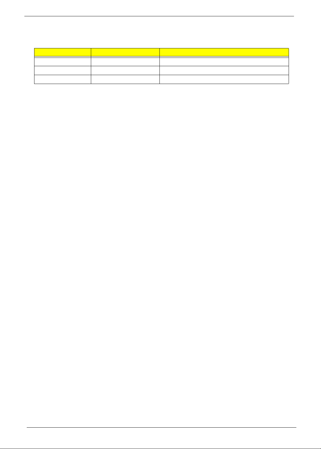
Conventions
The following conventions are used in this manual:
SCREEN MESSAGES Denotes actual messages that
NOTE Gives bits and pieces of additional
WARNING Alerts you to any damage that might
CAUTION Gives precautionary measures to
IMPORTANT Reminds you to do specific actions
appear on screen.
information related to the current
topic.
result from doing or not doing
specific actions.
avoid possible hardware or software
problems.
relevant to the accomplishment of
procedures.
iv
Page 5

Preface
Before using this information and the product it supports, please read the following general information.
1. This Service Guide provides you with all technical information relating to the BASIC CONFIGURATION
decided for Acer's "global" product offering. To better fit local market requirements and enhance product
competitiveness, your regional office MAY have decided to extend the functionality of a machine (e.g.
add-on card, modem, or extra memory capability). These LOCALIZED FEATURES will NOT be covered
in this generic service guide. In such cases, please contact your regional offices or the responsible
personnel/channel to provide you with further technical details.
2. Please note WHEN ORDERING FRU PARTS, that you should check the most up-to-date information
available on your regional web or channel. If, for whatever reason, a part number change is made, it will
not be noted in the printed Service Guide. For ACER-AUTHORIZED SERVICE PROVIDERS, your Acer
office may have a DIFFERENT part number code to those given in the FRU list of this printed Service
Guide. You MUST use the list provided by your regional Acer office to order FRU parts for repair and
service of customer machines.
v
Page 6

vi
Page 7

System Specifications 1
Features . . . . . . . . . . . . . . . . . . . . . . . . . . . . . . . . . . . . . . . . . . . . . . . . . . . . . . . . . . . .1
System Block Diagram . . . . . . . . . . . . . . . . . . . . . . . . . . . . . . . . . . . . . . . . . . . . . . . . .2
Your Graphics Dock Tour . . . . . . . . . . . . . . . . . . . . . . . . . . . . . . . . . . . . . . . . . . . . . . .3
Side Views . . . . . . . . . . . . . . . . . . . . . . . . . . . . . . . . . . . . . . . . . . . . . . . . . . . . . .3
Base View . . . . . . . . . . . . . . . . . . . . . . . . . . . . . . . . . . . . . . . . . . . . . . . . . . . . . . .4
Hardware Specifications and Configurations . . . . . . . . . . . . . . . . . . . . . . . . . . . . . . . .5
Machine Disassembly and Replacement 7
Disassembly Requirements . . . . . . . . . . . . . . . . . . . . . . . . . . . . . . . . . . . . . . . . . . . . .7
Related Information . . . . . . . . . . . . . . . . . . . . . . . . . . . . . . . . . . . . . . . . . . . . . . . .7
General Information . . . . . . . . . . . . . . . . . . . . . . . . . . . . . . . . . . . . . . . . . . . . . . . . . . .7
Pre-disassembly Instructions . . . . . . . . . . . . . . . . . . . . . . . . . . . . . . . . . . . . . . . .7
Disassembly Process . . . . . . . . . . . . . . . . . . . . . . . . . . . . . . . . . . . . . . . . . . . . . .8
Main Unit Disassembly Process . . . . . . . . . . . . . . . . . . . . . . . . . . . . . . . . . . . . . . . . . .8
Main Unit Disassembly Flowchart . . . . . . . . . . . . . . . . . . . . . . . . . . . . . . . . . . . . .8
Removing the Stand . . . . . . . . . . . . . . . . . . . . . . . . . . . . . . . . . . . . . . . . . . . . . .10
Removing the Monitor Mount . . . . . . . . . . . . . . . . . . . . . . . . . . . . . . . . . . . . . . .11
Removing the Upper Cover . . . . . . . . . . . . . . . . . . . . . . . . . . . . . . . . . . . . . . . .13
Removing the I/O Board . . . . . . . . . . . . . . . . . . . . . . . . . . . . . . . . . . . . . . . . . . .15
Removing the Mainboard . . . . . . . . . . . . . . . . . . . . . . . . . . . . . . . . . . . . . . . . . .17
Removing the Thermal Module . . . . . . . . . . . . . . . . . . . . . . . . . . . . . . . . . . . . . .18
Main Unit Reassembly Process . . . . . . . . . . . . . . . . . . . . . . . . . . . . . . . . . . . . . . . . .19
Replacing the Thermal Module . . . . . . . . . . . . . . . . . . . . . . . . . . . . . . . . . . . . . .19
Replacing the Mainboard . . . . . . . . . . . . . . . . . . . . . . . . . . . . . . . . . . . . . . . . . .20
Replacing the I/O Board . . . . . . . . . . . . . . . . . . . . . . . . . . . . . . . . . . . . . . . . . . .21
Replacing the Upper Cover . . . . . . . . . . . . . . . . . . . . . . . . . . . . . . . . . . . . . . . . .22
Replacing the Monitor Mount . . . . . . . . . . . . . . . . . . . . . . . . . . . . . . . . . . . . . . .24
Replacing the Stand . . . . . . . . . . . . . . . . . . . . . . . . . . . . . . . . . . . . . . . . . . . . . .25
Troubleshooting 27
Power On Issue . . . . . . . . . . . . . . . . . . . . . . . . . . . . . . . . . . . . . . . . . . . . . . . . .28
USB Failure . . . . . . . . . . . . . . . . . . . . . . . . . . . . . . . . . . . . . . . . . . . . . . . . . . . . .29
CRT Failure . . . . . . . . . . . . . . . . . . . . . . . . . . . . . . . . . . . . . . . . . . . . . . . . . . . . .30
HDMI Failure . . . . . . . . . . . . . . . . . . . . . . . . . . . . . . . . . . . . . . . . . . . . . . . . . . . .31
Other Function Fail . . . . . . . . . . . . . . . . . . . . . . . . . . . . . . . . . . . . . . . . . . . . . . .32
Connector Locations 33
Mainboard Top View . . . . . . . . . . . . . . . . . . . . . . . . . . . . . . . . . . . . . . . . . . . . . .33
Mainboard Bottom View . . . . . . . . . . . . . . . . . . . . . . . . . . . . . . . . . . . . . . . . . . .34
FRU (Field Replaceable Unit) List 35
Acer DynaVivid Graphics Dock Exploded Diagrams . . . . . . . . . . . . . . . . . . . . . . . . .36
Main Assembly . . . . . . . . . . . . . . . . . . . . . . . . . . . . . . . . . . . . . . . . . . . . . . . . . .36
FRU List . . . . . . . . . . . . . . . . . . . . . . . . . . . . . . . . . . . . . . . . . . . . . . . . . . . . . . .37
Test Compatible Components 39
Notebook vs. LCD Monitor Cross Test List . . . . . . . . . . . . . . . . . . . . . . . . . . . . .39
Notebook vs. Project Crosscheck List . . . . . . . . . . . . . . . . . . . . . . . . . . . . . . . .40
Online Support Information 43
Index 45
vii
Page 8

viii
Page 9

System Specifications
Features
Below is a brief summary of the graphics dock many features:
Video Controller
• ATI Mobility Radeon HD 4670
Dimensions and Weight)
• Weight: 0.65 kg
• Dimensions: 193.5 (W) x 193.5 (D) x 32.8 (H) mm
Power supply
• 3-pin 65 W AC adapter
Chapter 1
SI/O interface
• Six USB ports
• HDMI port
• HDCP supported external display (VGA) port
• DC-in jack for AC adapter
• Acer DynaVivid Graphics Dock connector
Environment
• Temperature:
• Operating: 5 °C to 35 °C
• Non-operating: -20 °C to 65 °C
• Humidity (non-condensing):
• Operating: 20% to 80%
• Non-operating: 20% to 80%
NOTE: The specifications listed above are for reference only. The exact configuration of the graphics dock
depends on the model purchased.
Chapter 1 1
Page 10
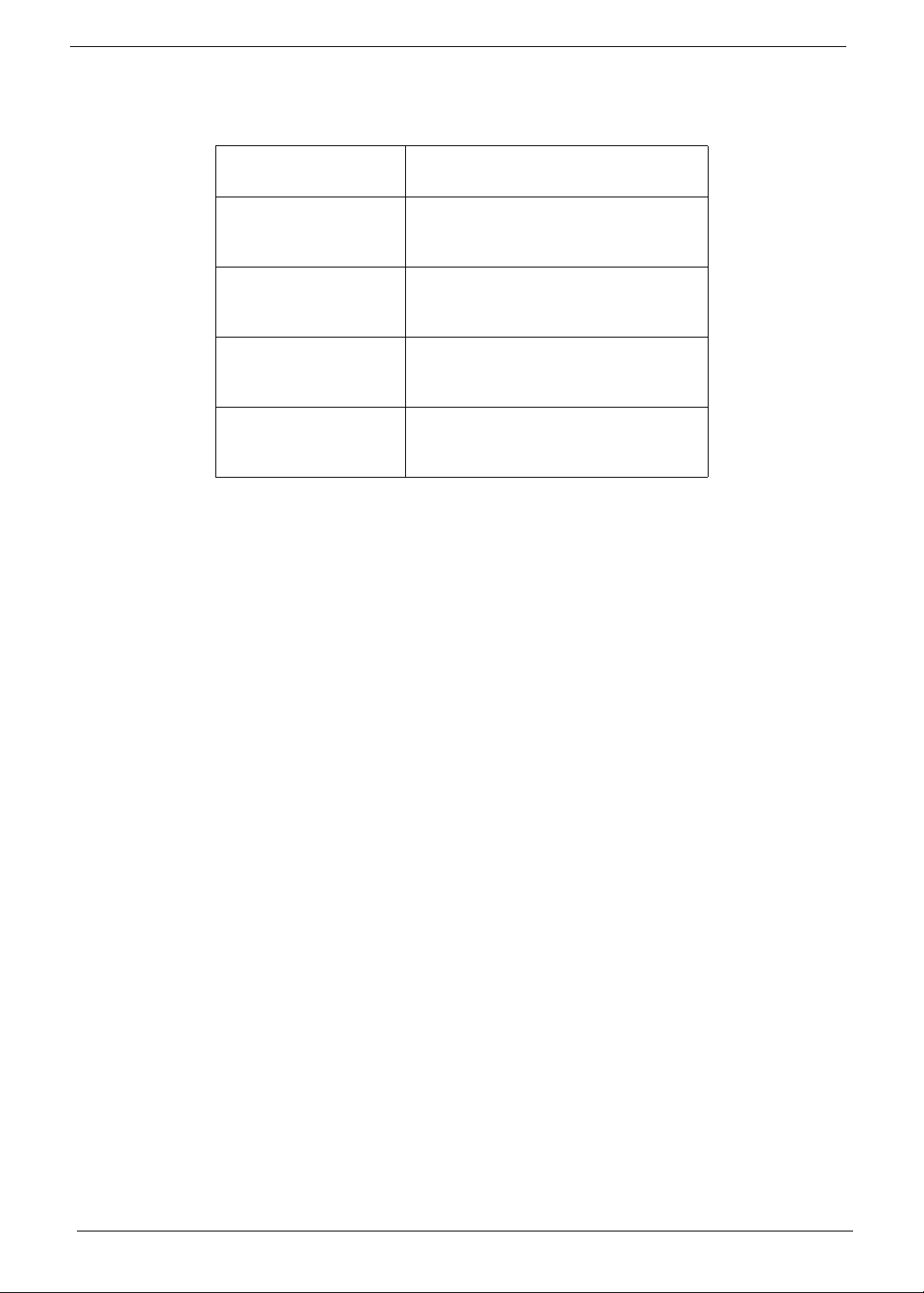
System Block Diagram
LASSO
CONNECTOR
CRT
CONNECTOR
HDMI
CONNECTOR
PCI-E x8
CRT
HDMI
ATi
M96-XT
FCBGA
962pin
FPC CONN
USB
HUB IC
DDR3 64M*16
DDR3 64M*16
CH-A
DDR3 64M*16
DDR3 64M*16
DDR3 64M*16
DDR3 64M*16
CH-B
DDR3 64M*16
DDR3 64M*16
USB
USB USB USB USBUSB
2 Chapter 1
Page 11
Your Graphics Dock Tour
12 345
2
This section provides an overview of the features and functions of the graphics dock.
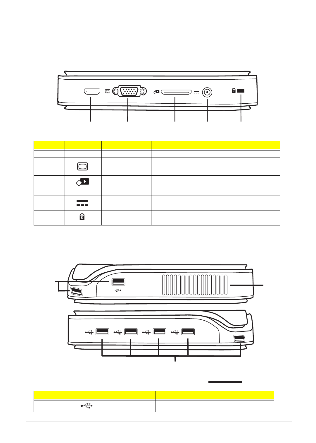
Side Views
HDMI
No. Icon Item Description
1 HDMI HDMI port Supports high-definition digital video connections.
2 External display
(VGA) port
Connects to a display device (e.g., external monitor,
LCD projector).
3 Acer DynaVivid
Graphics Dock
connector
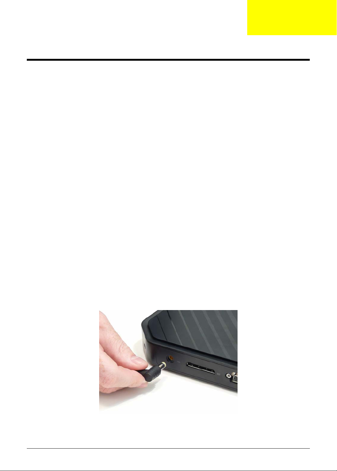
4 DC-in jack Connects to an AC adapter.
5 Kensington lock
slot
Connects to Acer DynaVivid Graphics Dock.
Connects to a Kensington-compatible computer
security lock.
USB Connector Sides View
1
1
No. Icon Item Description
1 USB 2.0 ports Connects to USB 2.0 devices.
Chapter 1 3
Page 12
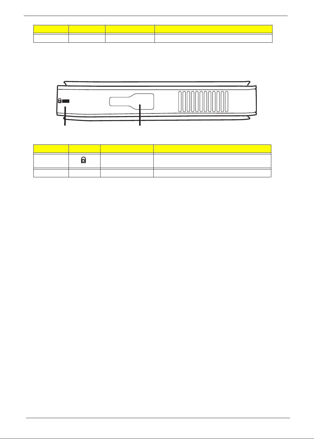
No. Icon Item Description
12
2 Ventilation Slots Air flow grill.
CAUTION: Always ensure that the ventilation slots are uncovered and air can freely flow through the grill.
Base View
No. Icon Item Description
1 Kensington lock
slot
2 Lock hole Secures the device to the stand.
Connects to a Kensington-compatible
computer security lock.
4 Chapter 1
Page 13
Hardware Specifications and Configurations
Video Chip
Item Specification
Video Chip M96 XT
Package 962 FCBGA
Features • lPCI Express Revision 2.0
• DirectX 10.1 with Shader Model 4.1
• VESA DisplayPort technologies
• Integrated HDMI and HDCP keys
• Unified Video Decoder 2.0 (UVD2)
• HD-DVD
• Blu-Ray decoder
CPU Fan True Value Table
CPU Temperature
(Celsius)
46 3200 31
56 3700 35
65 4200 38
72 4800 46
85 95%Duty 90%
Fan Speed (RPM) SPL Spec (dBA)
Throttling 50%: On= 81°C; OFF=90°C
OS shut down at 100°C; H/W shut down at 92°C
USB Hub
Item Specification
USB Hub GL852
Features • Compliant to USB specification Revision 2.0
• On-chip 8-bit micro-processor
• Multiple Transaction translator (MTT)
• Each downstream port supports two-color status indicator
• Supports both individual and gang modes
• Supports gang mode of power management and over-current
detection for downstream ports
• Conforms to bus power requirements
• Automatic switching between self-powered and bus-powered
modes
• Integrated USB 2.0 transceiver
System Memory
Item Specification
Supports memory size per socket DDR III 800MHz
Supports maximum memory size Total Maximum memory up to 128MBX8
Chapter 1 5
Page 14

6 Chapter 1
Page 15
Chapter 2
Machine Disassembly and Replacement
This chapter contains step-by-step procedures on how to disassemble the graphics dock for maintenance and
troubleshooting.
Disassembly Requirements
To disassemble the graphics dock, you need the following tools:
• Wrist grounding strap and conductive mat for preventing electrostatic discharge
• Philips screwdriver
• Plastic flat screwdriver
• Plastic tweezers
NOTE: The screws for the different components vary in size. During the disassembly process, group the
screws with the corresponding components to avoid mismatch when putting back the components.
Related Information
The product previews seen in the disassembly procedures may not represent the final product color or
configuration.
IMPORTANT: Cable paths and positioning may not represent the actual model. During the removal and
replacement of components, ensure all available cable channels and clips are used and that the cables are
replaced in the same position.
General Information
Pre-disassembly Instructions
Before proceeding with the disassembly procedure, make sure that you do the following:
1. Turn off the power to the system and remove all peripherals.
2. Unplug the AC adapter and all power and signal cables from the system.
3. Place the system on a flat, stable surface.
Chapter 2 7
Page 16
Disassembly Process
The disassembly process is divided into the following sections:
• Main unit disassembly
The flowcharts provided in the succeeding disassembly sections illustrate the entire disassembly sequence.
Observe the order of the sequence to avoid damage to any of the hardware components. For example, if you
want to remove the Mainboard, you must first remove the Keyboard, and LCD Module then disassemble the
inside assembly frame in that order.
Main Screw List
Screw Quantity Part Number
M2*6 15
Main Unit Disassembly Process
IMPORTANT: Cable paths and positioning may not represent the actual model. During the removal and
replacement of components, ensure all available cable channels and clips are used and that the cables are
replaced in the same position.
NOTE: The product previews seen in the disassembly procedures may not represent the final product color or
configuration.
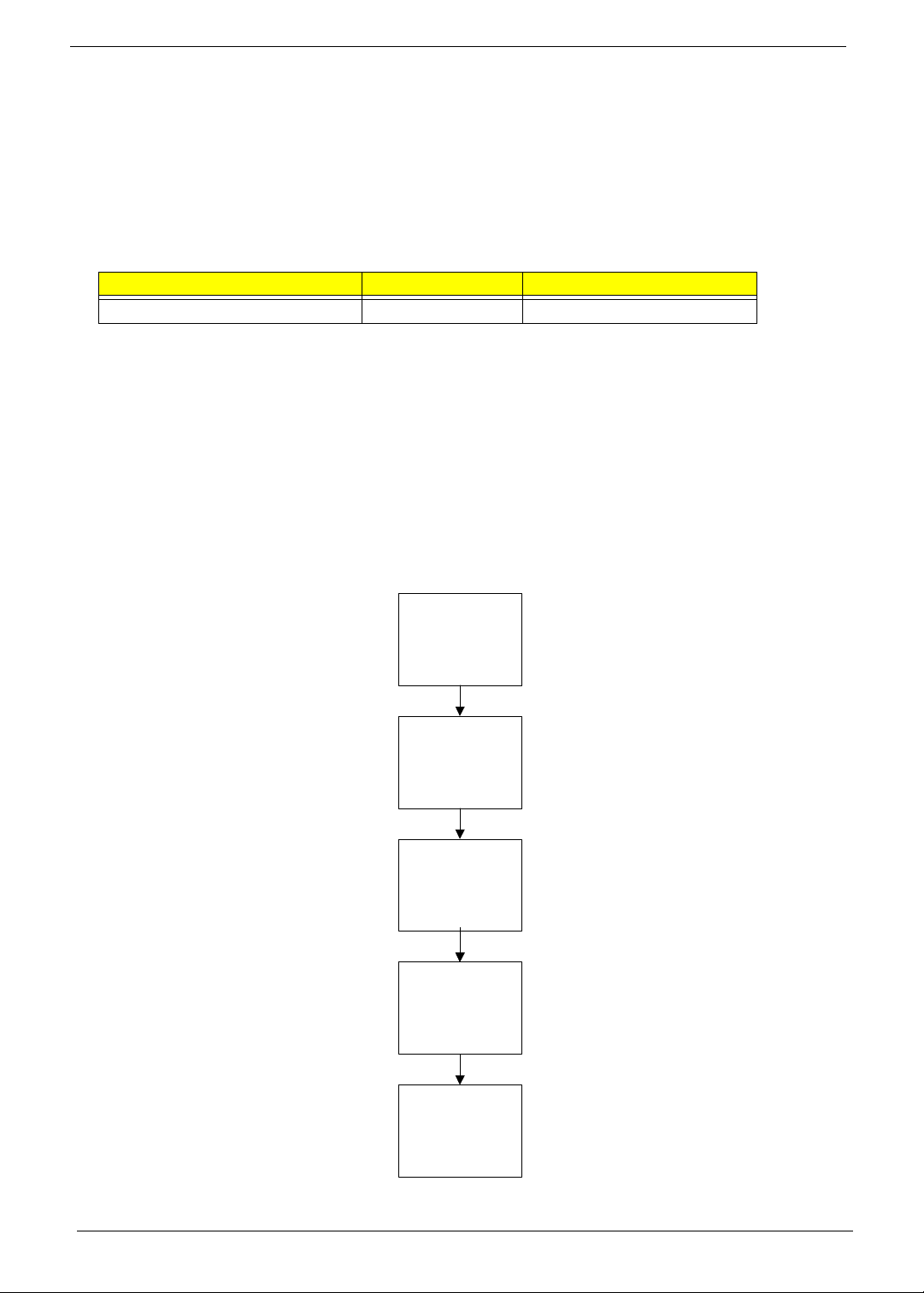
Main Unit Disassembly Flowchart
Remove External
Mounts before
proceeding
Remove
Upper Cover
Remove
I/O Board
Remove
Main Board
Remove
Thermal Module
8 Chapter 2
Page 17
Screw List
Step Screw Quantity Part No.
Main Unit Disassembly 2*6 15
Chapter 2 9
Page 18

Removing the Stand
1. Slide the stand off the base of the graphics dock.
10 Chapter 2
Page 19

Removing the Monitor Mount
1. Lay the graphics dock with monitor mount down with the monitor mount underneath.
2. Slide back the monitor mount lock to the open position (1) and firmly lift up the graphics dock (2).
2
3. Repeat step 2. on the other side.
1
2
1
Chapter 2 11
Page 20

4. Lift the graphics dock away from the monitor mount.
12 Chapter 2
Page 21

Removing the Upper Cover
If necessary first remove any mounts that may be attached to the unit. See “Removing the Stand” on page 10.
See “Removing the Monitor Mount” on page 11.
1. Remove the one (1) screw.
Step Size Quantity Screw Type
Removing the
Upper Cover
M2*6 1
2. Insert a plastic tweezer end or other soft tool to lever open the upper cover from the lower cover in the
side location shown.
NOTE: Ensure to open in the middle of the side as there are latches to either side of the location.
Chapter 2 13
Page 22

3. Pry up both corners of the side opened.
4. Proceed to pry open the upper cover around the edges of the graphic dock.
5. Lift the upper cover off.
14 Chapter 2
Page 23

Removing the I/O Board
1. See “Removing the Upper Cover” on page 13.
2. Remove the I/O cable.
3. Remove the four (4) screws.
Step Size Quantity Screw Type
Removing the IO
board.
Chapter 2 15
M2*6 4
Page 24

4. Lift the I/O board out.
16 Chapter 2
Page 25

Removing the Mainboard
1. See “Removing the Upper Cover” on page 13.
2. See “Removing the I/O Board” on page 15.
3. Remove the ten screws (10) from the mainboard.
Step Size Quantity Screw Type
Removing the
Mainboard
M2*6 10
4. Lift the mainboard out.
Chapter 2 17
Page 26

Removing the Thermal Module
1. See “Removing the Mainboard” on page 17.
2. Remove the thermal module cable.
3. Loosen the four captive screws in order: first 4, then 3 >2 >1.
4. Lift the thermal module out.
3
2
1
4
18 Chapter 2
Page 27

Main Unit Reassembly Process
Replacing the Thermal Module
1. Place the thermal module on the mainboard.
2. Tighten the four captive screws in order: first 1 then 2 > 3 > 4.
3
2
3. Connect the thermal module connector to the mainboard.
1
4
Chapter 2 19
Page 28

Replacing the Mainboard
1. Place the mainboard into the lower cover.
2. Replace the ten (10) screws.
Step Size Quantity Screw Type
Replacing the
Mainboard
20 Chapter 2
M2*6 10
Page 29

Replacing the I/O Board
1. Place the IO board into the lower cover.
2. Replace the four (4) screws.
Step Size Quantity Screw Type
Replacing the IO
board.
Chapter 2 21
M2*6 4
Page 30

3. Replace the IO cable.
Replacing the Upper Cover
1. Place the upper cover on the lower cover being careful to align the latch correctly.
22 Chapter 2
Page 31

2. Press down around the edges of the upper cover firmly.
3. Replace the one (1) screw.
Step Size Quantity Screw Type
Replacing the
Upper Cover
M2*6 1
Chapter 2 23
Page 32

Replacing the Monitor Mount
1. Place the graphics dock onto the monitor mount.
2. Slide the monitor mount latch switch open (1) and press the graphics dock down (2) until it latches in
place.
3. Repeat Step 2 on the other side.
2
1
2
1
24 Chapter 2
Page 33

Replacing the Stand
1. Slide the stand onto the graphics dock mounting bracket.
Chapter 2 25
Page 34

26 Chapter 2
Page 35

Chapter 3
Troubleshooting
Use the following procedure as a guide for system problems.
NOTE: The diagnostic tests are intended to test only Acer products. Non-Acer products, prototype cards, or
modified options can give false errors and invalid system responses.
1. Obtain the failing symptoms in as much detail as possible.
2. Verify the symptoms by attempting to re-create the failure by running the diagnostic test or by repeating
the same operation.
3. Use the following table with the verified symptom to determine which page to go to.
Symptoms (Verified) Go To
Power On Issue Page 28
USB Failure Page 29
CRT Failure Page 30
HDMI Failure Page 31
Other Functions Failure Page 32
4. If the issue is still not resolved, see “Online Support Information” on page 43.
Chapter 3 27
Page 36

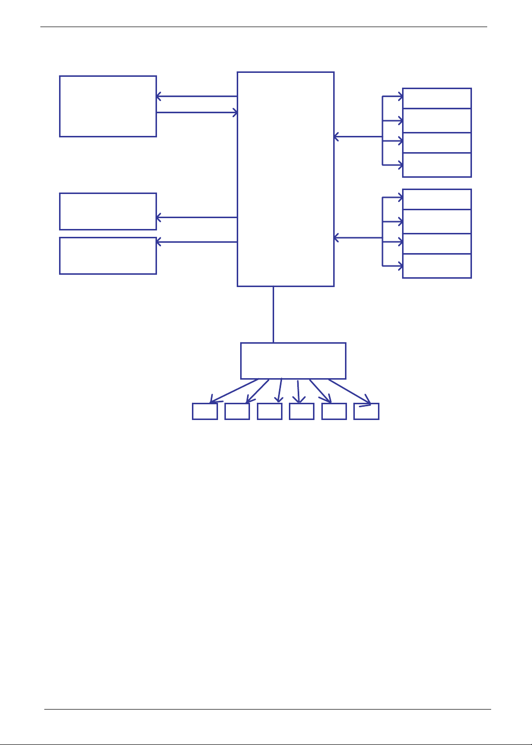
Power On Issue
If the system doesn’t power on, perform the following actions one at a time to correct the problem. Do not
replace non-defective FRUs:
Start
Start
OK
OK
Swap Lasso
Swap Lasso
Check
Check
Lasso cable
Lasso cable
Check AC
Check AC
adapter
adapter
NG
NG
OK
OK
NG
NG
cable
cable
Swap AC
Swap AC
adapter
adapter
OK
OK
Check M/B
Check M/B
Check USB/B
Check USB/B
LED light on
LED light on
or off
or off
NG
NG
power
power
Swap M/B
The Graphics Dock Shuts Down Intermittently
If the system powers off at intervals, perform the following actions one at a time to correct the problem.
1. Check the power cable is properly connected to the graphics dock and the electrical outlet.
2. Remove any extension cables between the graphics dock and the outlet.
3. Remove any surge protectors between the graphics dock and the electrical outlet. Plug the graphics dock
directly into a known good electrical outlet.
4. Remove all external and non-essential hardware connected to the graphics dock that are not necessary to
the graphics dock.
5. If the Issue is still not resolved, see see “Online Support Information” on page 43.
28 Chapter 3
Page 37

USB Failure
If there is an issue with the USB port(s), perform the following actions one at a time to correct the problem. Do
not replace non-defective FRUs:
Start
OK
OK
Re-assemble the
Check USB/B to
Check USB/B to
M/B FPC
M/B FPC
NG
NG
OK
OK
Re-assemble the
USB/B FPC
USB/B FPC
NG
Check USB/B Swap USB/B
Check USB/B Swap USB/B
Swap M/B
Swap M/B
NG
Chapter 3 29
Page 38

CRT Failure
If the system doesn’t power on, perform the following actions one at a time to correct the problem. Do not
replace non-defective FRUs:
Start
OK
OK
Re-assembly/Swap
NG
Check CRT cable
Check CRT cable
OK
OK
NG
CRT cable
Check MB CRT
Check MB CRT
co nnec tor
co nnec tor
NG
NG
Swap M/B
30 Chapter 3
Page 39

HDMI Failure
If there is a failure with the HDMI, perform the following actions one at a time to correct the problem. Do not
replace non-defective FRUs:
Start
OK
OK
Check HDMI
Check HDMI
cable
cable
OK
OK
NG
NG
Re-assemble/Swap
Re-assemble/Swap
HDMI cable
HDMI cable
Check M/B
Check M/B
HDMI connector
HDMI connector
NG
NG
Swap M/B
Chapter 3 31
Page 40

Other Function Fail
If there is a failure not previously noted, perform the following actions one at a time to correct the problem. Do
not replace non-defective FRUs:
Start
OK
OK
Update driver to
Check Driver is
latest
No
No
OK
OK
Update driver to
latest
latest
Check test fixture
Swap M/B
NG
NG
Fi x test fixture
Fi x test fixture
32 Chapter 3
Page 41

Connector Locations
Mainboard Top View
Chapter 4
Connector Description Connector Description
U34 VRAM U32 VRAM
U24 VRAM CN9 FCC Connector
U25 VRAM
Chapter 4 33
Page 42

Mainboard Bottom View
Connector Description Connector Description
U1 M96-M2 U21 VRAM
CN14 Fan Connector U28 VRAM
CN15 CRT U31 VRAM
CN1 Lasso Connector U33 VRAM
PJ1 DC Jack
34 Chapter 4
Page 43

Chapter 5
FRU (Field Replaceable Unit) List
This chapter gives you the FRU (Field Replaceable Unit) listing in global configurations of the Graphics Dock
to this chapter whenever ordering for parts to repair or for RMA (Return Merchandise Authorization).
Please note that WHEN ORDERING FRU PARTS, you should check the most up-to-date information available
on your regional web or channel. For whatever reasons a part number change is made, it will not be noted on
the printed Service Guide. For ACER AUTHORIZED SERVICE PROVIDERS, your Acer office may have a
DIFFERENT part number code from those given in the FRU list of this printed Service Guide. You MUST use
the local FRU list provided by your regional Acer office to order FRU parts for repair and service of customer
machines.
NOTE: To scrap or to return the defective parts, you should follow the local government ordinance or
regulations on how to dispose it properly, or follow the rules set by your regional Acer office on how to
return it.
Chapter 5 35
Page 44

Acer DynaVivid Graphics Dock Exploded Diagrams
Main Assembly
Item Description Part Number
1 Upper Cover
2 Lower Cover
3 Monitor Mount
4Stand
5 Thermal Module
6 Thermal Bracket
7 IO Board
8 Mainboard
36 Chapter 5
Page 45

FRU List
CA TEGORY PARTNAME ACERPARTNO.
ADAPTER
BOARD
CABLE
AP.06501.026
AP.06503.024
AP.0650A.012
POWER CORD US 3PIN ROHS 27.TAXV7.001
CASE/COVER/BRACKET ASSEMBLY
Chapter 5 37
Page 46

CA TEGORY PARTNAME ACERPARTNO.
MAINBOARD
HEA TSINK
SCREW
38 Chapter 5
Page 47

n
n
Appendix A
Test Compatible Components
This graphics dock compatibility is tested and verified by Acer’s internal testing department. All of its system functions are tested under Windows® XP Home, Windows® XP Pro environment.
Refer to the following lists for components, adapter cards, and peripherals which have passed these tests. Regarding configuration, combination and test procedures, please refer to the Test Report released by the
Acer Mobile System Testing Department.
Notebook vs. LCD Monitor Cross Test List
Driver vendor/version: 8.631.1RC7
Sys Bios: VBIOS: LM Ver. 3103 / A10 / 3.0.03
Dock: Wi(Allow additional XGP)
Acer LCD Monitor vs. NB External Single mode Fn+F5 switch test (3 times) Driver Utility switch test
Flicker
(w/ Monitor
Test, gray
color )
Power
Sequence
NB LCD Clone External 800x600 1024x768 Extended NB LCD Clone External Extended
Description
0931-0033
:Limitation
0931-0033
:Limitation
Display
Model Name Input Optimal Resolutio
Size
17" B173(v)
X193HQ(x)
19"
20" V203H(v)
21" H223HQ(v)
23"
24" H243H(x)
V193(x) D-Sub 1280x1024@75Hz P P P P P N/A N/A N/A N/A N/A N/A P N/A P P
Viseo
193Ws(v)
Viseo
223Ws(v)
X233H(x)
B233HU(t)
V243HQ(t)
PnP
Monitor
Check
D-Sub 1280x1024@60Hz PP P P PNaNaNaNaNaNaPN/APP
DVI 1280x1024@61Hz N/A N/A N/A N/A N/A N/A N/A N/A N/A N/A N/A N/A N/A N/A N/A
D-Sub 1366x768@60Hz P N/A P P P N/A N/A N/A N/A N/A N/A P N/A P P
DVI 1366x768@60Hz N/A N/A N/A N/A N/A N/A N/A N/A N/A N/A N/A N/A N/A Na N/A
D-Sub 1440x900@60Hz P P P P P N/A N/A N/A N/A N/A N/A P N/A P P
DVI 1440x900@60Hz N/A N/A N/A N/A N/A N/A N/A N/A N/A N/A N/A N/A N/A N/A N/A
D-Sub 1600x900@60Hz P P P P P N/A N/A N/A N/A N/A N/A P N/A P P
DVI 1600x900@60Hz N/A N/A N/A N/A N/A N/A N/A N/A N/A N/A N/A N/A N/A N/A N/A
D-Sub 1920x1080@60Hz P P P P P N/A N/A N/A N/A N/A N/A P N/A P P
DVI 1920x1080@60Hz N/A N/A N/A N/A N/A N/A N/A N/A N/A N/A N/A N/A N/A N/A N/A
HDMI 1920x1080@60Hz P P P P P N/A N/A N/A N/A N/A N/A P N/A P P
D-Sub 1680x1050@60Hz P P P P P N/A N/A N/A N/A N/A N/A P N/A P P
DVI 1680x1050@60Hz N/A N/A N/A N/A N/A N/A N/A N/A N/A N/A N/A N/A N/A N/A N/A
D-Sub 1920x1080@60Hz P P P P P N/A N/A N/A N/A N/A N/A P N/A P P
DVI 1920x1080@60Hz N/A N/A N/A N/A N/A N/A N/A N/A N/A N/A N/A N/A N/A N/A N/A
HDMI 1920x1080@60Hz P P P P P N/A N/A N/A N/A N/A N/A P N/A P P
USB 1920x1080@60Hz N/A N/A N/A N/A N/A N/A N/A N/A N/A N/A N/A N/A N/A N/A N/A
D-Sub 2048x1152@60Hz P P P P P N/A N/A N/A N/A N/A N/A P Na P P
DVI 2048x1152@60Hz N/A N/A N/A N/A N/A N/A N/A N/A N/A N/A N/A N/A N/A N/A N/A
HDMI 2048x1152@60Hz P P P P P N/A N/A N/A N/A N/A N/A P N/A P P
D-Sub 1920x1080@60Hz P P P P P N/A N/A N/A N/A N/A N/A P N/A P P
DVI 1920x1080@60Hz N/A N/A N/A N/A N/A N/A N/A N/A N/A N/A N/A N/A N/A N/A N/A
D-Sub 1920x1080@60Hz P P P P P N/A N/A N/A N/A N/A N/A P N/A P P
DVI 1920x1080@60Hz N/A N/A N/A N/A N/A N/A N/A N/A N/A N/A N/A N/A N/A N/A N/A
HDMI 1920x1080@60Hz P P P P P N/A N/A N/A N/A N/A N/A P N/A P P
Test
Resolution
Focus
(w/ Monitor
Test)
Issue
Driver vendor/version: 8.631.1RC7
Sys Bios: VBIOS: LM Ver. 3103 / A10 / 3.0.03
Dock: Wi(Allow additional XGP)
Acer LCD Monitor vs. NB External Single mode
Display
Model Name Input Optimal Resolutio
Size
17" B173(v)
X193HQ(x)
19"
20" V203H(v)
21" H223HQ(v)
23"
24" H243H(x)
V193(x) D-Sub 1280x1024@75Hz PP P P PNaNaNaNaNaNaPNaPP
Viseo
193Ws(v)
Viseo
223Ws(v)
X233H(x)
B233HU(t)
V243HQ(t)
D-Sub 1280x1024@60Hz PP P P PNaNaNaNaNaNaPNaPP
DVI 1280x1024@61Hz Na Na Na Na Na Na Na Na Na Na Na Na Na Na Na
D-Sub 1366x768@60Hz PP P P PNaNaNaNaNaNaPNaPP
DVI 1366x768@60Hz Na Na Na Na Na Na Na Na Na Na Na Na Na Na Na
D-Sub 1440x900@60Hz PP P P PNaNaNaNaNaNaPNaPP
DVI 1440x900@60Hz Na Na Na Na Na Na Na Na Na Na Na Na Na Na Na
D-Sub 1600x900@60Hz PP P P PNaNaNaNaNaNaPNaPP
DVI 1600x900@60Hz Na Na Na Na Na Na Na Na Na Na Na Na Na Na Na
D-Sub 1920x1080@60Hz PP P P PNaNaNaNaNaNaPNaPP
DVI 1920x1080@60Hz Na Na Na Na Na Na Na Na Na Na Na Na Na Na Na
HDMI 1920x1080@60Hz Na Na Na Na Na Na Na Na Na Na Na Na Na Na Na
D-Sub 1680x1050@60Hz PP P P PNaNaNaNaNaNaPNaPP
DVI 1680x1050@60Hz Na Na Na Na Na Na Na Na Na Na Na Na Na Na Na
D-Sub 1920x1080@60Hz PP P P PNaNaNaNaNaNaPNaPP
DVI 1920x1080@60Hz Na Na Na Na Na Na Na Na Na Na Na Na Na Na Na
HDMI 1920x1080@60Hz Na Na Na Na Na Na Na Na Na Na Na Na Na Na Na
USB 1920x1080@60Hz Na Na Na Na Na Na Na Na Na Na Na Na Na Na Na
D-Sub 2048x1152@60Hz PP P P PNaNaNaNaNaNaPNaPP
DVI 2048x1152@60Hz Na Na Na Na Na Na Na Na Na Na Na Na Na Na Na
HDMI 2048x1152@60Hz Na Na Na Na Na Na Na Na Na Na Na Na Na Na Na
D-Sub 1920x1080@60Hz PP P P PNaNaNaNaNaNaPNaPP
DVI 1920x1080@60Hz Na Na Na Na Na Na Na Na Na Na Na Na Na Na Na
D-Sub 1920x1080@60Hz PP P P PNaNaNaNaNaNaPNaPP
DVI 1920x1080@60Hz Na Na Na Na Na Na Na Na Na Na Na Na Na Na Na
HDMI 1920x1080@60Hz Na Na Na Na Na Na Na Na Na Na Na Na Na Na Na
PnP
Monitor
Check
Test
Resolution
Focus
(w/ Monitor
Test)
Flicker
(w/ Monitor
Test, gray
color )
Power
Sequence
Fn+F5 Driver Utility
NB LCD Clone External 800x600 1024x768 Extended NB LCD Clone External Extended
Issue
Description
Appendix A 39
Page 48

Driver vendor/version: 8.631.1RC7
n
Sys Bios: VBIOS: LM Ver. 3103 / A10 / 3.0.03
Dock: Wi(Accelerate Existing)
Display
Model Name Input Optimal Resolutio
Size
17" B173(v)
X193HQ(x)
19"
20" V203H(v)
21" H223HQ(v)
23"
24" H243H(x)
V193(x) D-Sub 1280x1024@75Hz PP P P PNaNaNaNaNaNaPNaPP
Viseo
193Ws(v)
Viseo
223Ws(v)
X233H(x)
B233HU(t)
V243HQ(t)
Acer LCD Monitor vs. NB External Single mode
PnP
Monitor
Check
D-Sub 1280x1024@60Hz PP P P PNaNaNaNaNaNaPNaPP
DVI 1280x1024@61Hz Na Na Na Na Na Na Na Na Na Na Na Na Na Na Na
D-Sub 1366x768@60Hz PP P P PNaNaNaNaNaNaPNaPP
DVI 1366x768@60Hz Na Na Na Na Na Na Na Na Na Na Na Na Na Na Na
D-Sub 1440x900@60Hz PP P P PNaNaNaNaNaNaPNaPP
DVI 1440x900@60Hz Na Na Na Na Na Na Na Na Na Na Na Na Na Na Na
D-Sub 1600x900@60Hz PP P P PNaNaNaNaNaNaPNaPP
DVI 1600x900@60Hz Na Na Na Na Na Na Na Na Na Na Na Na Na Na Na
D-Sub 1920x1080@60Hz PP P P PNaNaNaNaNaNaPNaPP
DVI 1920x1080@60Hz Na Na Na Na Na Na Na Na Na Na Na Na Na Na Na
HDMI 1920x1080@60Hz Na Na Na Na Na Na Na Na Na Na Na Na Na Na Na
D-Sub 1680x1050@60Hz PP P P PNaNaNaNaNaNaPNaPP
DVI 1680x1050@60Hz Na Na Na Na Na Na Na Na Na Na Na Na Na Na Na
D-Sub 1920x1080@60Hz PP P P PNaNaNaNaNaNaPNaPP
DVI 1920x1080@60Hz Na Na Na Na Na Na Na Na Na Na Na Na Na Na Na
HDMI 1920x1080@60Hz Na Na Na Na Na Na Na Na Na Na Na Na Na Na Na
USB 1920x1080@60Hz Na Na Na Na Na Na Na Na Na Na Na Na Na Na Na
D-Sub 2048x1152@60Hz PP P P PNaNaNaNaNaNaPNaPP
DVI 2048x1152@60Hz Na Na Na Na Na Na Na Na Na Na Na Na Na Na Na
HDMI 2048x1152@60Hz Na Na Na Na Na Na Na Na Na Na Na Na Na Na Na
D-Sub 1920x1080@60Hz PP P P PNaNaNaNaNaNaPNaPP
DVI 1920x1080@60Hz Na Na Na Na Na Na Na Na Na Na Na Na Na Na Na
D-Sub 1920x1080@60Hz PP P P PNaNaNaNaNaNaPNaPP
DVI 1920x1080@60Hz Na Na Na Na Na Na Na Na Na Na Na Na Na Na Na
HDMI 1920x1080@60Hz Na Na Na Na Na Na Na Na Na Na Na Na Na Na Na
Test
Resolution
Focus
(w/ Monitor
Test)
Flicker
(w/ Monitor
Test, gray
color )
Power
Sequence
Fn+F5 Driver Utility
NB LCD Clone External 800x600 1024x768 Extended NB LCD Clone External Extended
Issue
Description
Remarks:
"P"=> Test Passed
"F1"=> Test Failed with Severity 1 issues: Critical bug which will impact user behavior and must be fixed immediately.
"F2"=> Test Failed with Severity 2 issues: Serious bug which must be fixed before shipping.
"F3"=> Test Failed with Severity 3 issues: Minor issue which could be acceptable.
"N/A"=> No available port for test
Notebook vs. Project Crosscheck List
Driver vendor/version: 8.631.1RC7
Sys Bios: VBIOS: LM Ver. 3103 / A10 / 3.0.03
Dock: Wi(Allow additional XGP)
Acer Projector vs. NB External Single mode Fn+F5 switch test (3 times) Driver Utility switch test
Model
Name
k10 D-Sub Native SVGA, 800x600@60Hz P P P P P N/A N/A N/A N/A N/A N/A P P P P
X1230 D-Sub Native SVGA, 1024x768@60Hz P P P P P N/A N/A N/A N/A N/A N/A P P P P
X1260 D-Sub Native SVGA, 1024x768@60Hz P P P P P N/A N/A N/A N/A N/A N/A P P P P
P3250
H5350
S1200
P1266i
P5280
P7270i
P5370W
Input Native Resolution
D-Sub Native XGA, 1024x768@60Hz P P P P P N/A N/A N/A N/A N/A N/A P P P P
HDMI Native XGA, 1024x768@60Hz P P P P P N/A N/A N/A N/A N/A N/A P P P P
D-Sub Native 720P, 1280x720@60Hz P P P P P N/A N/A N/A N/A N/A N/A P P P P
HDMI Native 720P, 1280x720@60Hz P P P P P N/A N/A N/A N/A N/A N/A P P P P
D-Sub Native XGA, 1024x768@60Hz P P P P P N/A N/A N/A N/A N/A N/A P P P P
HDMI Native XGA, 1024x768@60Hz P P P P P N/A N/A N/A N/A N/A N/A P P P P
D-Sub Native XGA, 1024x768@60Hz P P P P P N/A N/A N/A N/A N/A N/A P P P P
DVI Native XGA, 1024x768@60Hz N/A N/A N/A N/A N/A N/A N/A N/A N/A N/A N/A N/A N/A N/A N/A
D-Sub Native XGA, 1024x768@60Hz P P P P P N/A N/A N/A N/A N/A N/A P P P P
DVI Native XGA, 1024x768@60Hz N/A N/A N/A N/A N/A N/A N/A N/A N/A N/A N/A N/A N/A N/A N/A
HDMI Native XGA, 1024x768@60Hz P P P P P N/A N/A N/A N/A N/A N/A P P P P
D-Sub Native XGA, 1024x768@60Hz P P P P P N/A N/A N/A N/A N/A N/A P P P P
DVI Native XGA, 1024x768@60Hz N/A N/A N/A N/A N/A N/A N/A N/A N/A N/A N/A N/A N/A N/A N/A
HDMI Native XGA, 1024x768@60Hz P P P P P N/A N/A N/A N/A N/A N/A P P P P
D-Sub Native XGA, 1280x800@60Hz P P P P P N/A N/A N/A N/A N/A N/A P P P P
DVI Native XGA, 1280x800@60Hz N/A N/A N/A N/A N/A N/A N/A N/A N/A N/A N/A N/A N/A N/A N/A
HDMI Native XGA, 1280x800@60Hz P P P P P N/A N/A N/A N/A N/A N/A P P P P
PnP
Monitor
Check
Test
Resolution
Focus (w/
Monitor
Test)
Flicker (w/
Monitor Test,
gray color )
Power
Sequence
NB
Clone External
LCD
800x6001024x
768
Extended
NB
Clone External Extended
LCD
40 Appendix A
Page 49

Driver vendor/version: 8.631.1RC7
Sys Bios: VBIOS: LM Ver. 3103 / A10 / 3.0.03
Dock: Wi(Allow additional XGP)
Acer Projector vs. NB External Single mode Fn+F5 Driver Utility
Model
Name
k10 D-Sub Native SVGA, 800x600@60Hz PP P P PNaNaNaNaNaNaPPPP
X1230 D-Sub Native SVGA, 1024x768@60Hz PP P P PNaNaNaNaNaNaPPPP
X1260 D-Sub Native SVGA, 1024x768@60Hz PP P P PNaNaNaNaNaNaPPPP
P3250
H5350
S1200
P1266i
P5280
P7270i
P5370W
Input Native Resolution
D-Sub Native XGA, 1024x768@60Hz PP P P PNaNaNaNaNaNaPPPP
HDMI Native XGA, 1024x768@60Hz PP P P PNaNaNaNaNaNaPPPP
D-Sub Native 720P, 1280x720@60Hz PP P P PNaNaNaNaNaNaPPPP
HDMI Native 720P, 1280x720@60Hz PP P P PNaNaNaNaNaNaPPPP
D-Sub Native XGA, 1024x768@60Hz PP P P PNaNaNaNaNaNaPPPP
HDMI Native XGA, 1024x768@60Hz PP P P PNaNaNaNaNaNaPPPP
D-Sub Native XGA, 1024x768@60Hz PP P P PNaNaNaNaNaNaPPPP
DVI Native XGA, 1024x768@60Hz Na Na Na Na Na Na Na Na Na Na Na Na Na Na Na
D-Sub Native XGA, 1024x768@60Hz PP P P PNaNaNaNaNaNaPPPP
DVI Native XGA, 1024x768@60Hz Na Na Na Na Na Na Na Na Na Na Na Na Na Na Na
HDMI Native XGA, 1024x768@60Hz PP P P PNaNaNaNaNaNaPPPP
D-Sub Native XGA, 1024x768@60Hz PP P P PNaNaNaNaNaNaPPPP
DVI Native XGA, 1024x768@60Hz Na Na Na Na Na Na Na Na Na Na Na Na Na Na Na
HDMI Native XGA, 1024x768@60Hz PP P P PNaNaNaNaNaNaPPPP
D-Sub Native XGA, 1280x800@60Hz PP P P PNaNaNaNaNaNaPPPP
DVI Native XGA, 1280x800@60Hz Na Na Na Na Na Na Na Na Na Na Na Na Na Na Na
HDMI Native XGA, 1280x800@60Hz PP P P PNaNaNaNaNaNaPPPP
PnP
Monitor
Check
Test
Resolution
Focus
(w/ Monitor
Test)
Flicker
(w/ Monitor
Test, gray
color )
Power
Sequence
NB
Clone External
LCD
800x6001024x
768
Extended
NB
Clone External Extended
LCD
Driver vendor/version: 8.631.1RC7
Sys Bios: VBIOS: LM Ver. 3103 / A10 / 3.0.03
Dock: Wi(Accelerate Existing)
Acer Projector vs. NB External Single mode Fn+F5 Driver Utility
Model
Name
k10 D-Sub Native SVGA, 800x600@60Hz PP P P PNaNaNaNaNaNaPPPP
X1230 D-Sub Native SVGA, 1024x768@60Hz PP P P PNaNaNaNaNaNaPPPP
X1260 D-Sub Native SVGA, 1024x768@60Hz PP P P PNaNaNaNaNaNaPPPP
P3250
H5350
S1200
P1266i
P5280
P7270i
P5370W
Input Native Resolution
D-Sub Native XGA, 1024x768@60Hz PP P P PNaNaNaNaNaNaPPPP
HDMI Native XGA, 1024x768@60Hz PP P P PNaNaNaNaNaNaPPPP
D-Sub Native 720P, 1280x720@60Hz PP P P PNaNaNaNaNaNaPPPP
HDMI Native 720P, 1280x720@60Hz PP P P PNaNaNaNaNaNaPPPP
D-Sub Native XGA, 1024x768@60Hz PP P P PNaNaNaNaNaNaPPPP
HDMI Native XGA, 1024x768@60Hz PP P P PNaNaNaNaNaNaPPPP
D-Sub Native XGA, 1024x768@60Hz PP P P PNaNaNaNaNaNaPPPP
DVI Native XGA, 1024x768@60Hz Na Na Na Na Na Na Na Na Na Na Na Na Na Na Na
D-Sub Native XGA, 1024x768@60Hz PP P P PNaNaNaNaNaNaPPPP
DVI Native XGA, 1024x768@60Hz Na Na Na Na Na Na Na Na Na Na Na Na Na Na Na
HDMI Native XGA, 1024x768@60Hz PP P P PNaNaNaNaNaNaPPPP
D-Sub Native XGA, 1024x768@60Hz PP P P PNaNaNaNaNaNaPPPP
DVI Native XGA, 1024x768@60Hz Na Na Na Na Na Na Na Na Na Na Na Na Na Na Na
HDMI Native XGA, 1024x768@60Hz PP P P PNaNaNaNaNaNaPPPP
D-Sub Native XGA, 1280x800@60Hz PP P P PNaNaNaNaNaNaPPPP
DVI Native XGA, 1280x800@60Hz Na Na Na Na Na Na Na Na Na Na Na Na Na Na Na
HDMI Native XGA, 1280x800@60Hz PP P P PNaNaNaNaNaNaPPPP
PnP
Monitor
Check
Test
Resolution
Focus
(w/ Monitor
Test)
Flicker
(w/ Monitor
Test, gray
color )
Power
Sequence
NB
Clone External
LCD
800x6001024x
768
Extended
NB
Clone External Extended
LCD
Remarks:
"P"=> Test Passed
"F1"=> Test Failed with Severity 1 issues: Critical bug which will impact user behavior and must be fixed immediately.
"F2"=> Test Failed with Severity 2 issues: Serious bug which must be fixed before shipping.
"F3"=> Test Failed with Severity 3 issues: Minor issue which could be acceptable.
"N/A"=> No available port for test
Appendix A 41
Page 50

Page 51

Appendix B
Online Support Information
This section describes online technical support services available to help you repair your Acer Systems.
If you are a distributor, dealer, ASP or TPM, please refer your technical queries to your local Acer branch
office. Acer Branch Offices and Regional Business Units may access our website. However some information
sources will require a user i.d. and password. These can be obtained directly from Acer CSD Taiwan.
Acer's Website offers you convenient and valuable support resources whenever you need them.
In the Technical Information section you can download information on all of Acer's Graphic Docks, Notebo ok,
Desktop and Server models including:
• Service guides for all models
• User's manuals
• Training materials
• Bios updates
• Software utilities
• Spare parts lists
• TABs (Te c hnical Announcement Bulletin)
For these purposes, we have included an Acrobat File to facilitate the problem-free downloading of our
technical material.
Also contained on this website are:
• Detailed information on Acer's International Traveler's Warranty (ITW)
• Returned material authorization procedures
• An overview of all the support services we offer, accompanied by a list of telephone, fax and email
contacts for all your technical queries.
We are always looking for ways to optimize and improve our services, so if you have any suggestions or
comments, please do not hesitate to communicate these to us.
Appendix B 43
Page 52

44 Appendix B
Page 53

Index
C
Common Problems 28, 29
CRT Cable
Removing 17, 20
D
Display 2
E
External Module Disassembly
Flowchart 8
F
Features 1
FRU (Field Replaceable Unit) List 35
H
Hot Keys 5
J
Block Diagram 2
T
Test Compatible Components 39
Thermal Module
Removing 18, 19
Troubleshooting
Power On 28, 29
U
Upper Cover
Removing 10, 13
W
Windows 2000 Environment Test 39
Jumper and Connector Locations 33
L
LCD Module Disassembly
Flowchart 19
M
Main Unit Disassembly
Flowchart 8
Mainboard
Removing 17, 20
Memory Check 28, 29
O
Online Support Information 43
P
Panel 3
Power On Failure 28, 29
S
System
45
Page 54

464748
Page 55

Page 56

 Loading...