

Page 1

C h a p t e r
1
System Board
1.1 Features
The DX6G Plus is a dual-processor system board built on an
extended ATX baseboard utilizing two Pentium®II processors running
at 400/100 and 450/100 MHz or two Pentium®III processors running
at 500/100 and 550/100 MHz. It is integrated with the Intel 440GX
system controller, which consists of the PCI/AGP controller and the
PCI/ISA IDE accelerator (PIIX4E).
The Pentium®II and Pentium®III processor implements a Dynamic
Execution micro-architecture - a unique combination of multiple
branch prediction, data flow analysis, and speculative execution. This
means that it can deliver higher performance than the previous
Pentium®processor while maintaining binary compatibility with all
previous Intel Architecture processors.
The PCI/AGP controller host bus interface supports both Pentium®II
and Pentium®III with 100 MHz bus frequency. It also provides a 72bit DIMM that supports synchronous DRAM (SDRAM) DIMMs. The
PCI/AGP controller introduces a new technology, which is the
Accelerated Graphics Port (AGP) interface. Supporting up to
533MB/sec MHz data transfer rate, the AGP interface boosts graphics
performance.
The PIIX4E is a multifunctional PCI device controller implementing
system functions including PCI IDE, universal serial bus (USB)
host/hub, and enhanced power management. It also supports Ultra
DMA/33 synchronous DMA-compatible devices.
System Board 1-1
Page 2

The four DIMM sockets on board allow memory upgrade to a
maximum of 2048 MB and supports 72-bit DIMM using synchronous
DRAM (SDRAM) DIMMs.
Two 16-bit Ultra-2 SCSI (Small Computer System Interface) and an
8-bit fast narrow SCSI comes with the system board to connect SCSI
devices.
The system board also supports the USB (Universal Serial Bus)
connector, and other standard features such as two UART NS16C550
serial ports, one enhanced parallel port with Enhanced Parallel Port
(EPP)/Extended Capabilities Port (ECP) feature, a diskette drive
interface, and two embedded hard disk interfaces. The board also
includes a built-in 10/100 Mb/s Intel 82558 LAN chip that supports
Wake-On-LAN (WOL).
The system supports the power-management function that conforms
to the power-saving standards of the U.S. Environmental Protection
Agency (EPA) Energy Star program. It also offers the Plug-and-Play
feature. This feature saves the user from configuration troubles, thus
making the system more user-friendly. The system board support Intel
LDCM© (LAN Desktop Client Manager) which will detect problems in
CPU thermal condition, CPU working voltage, CPU fan and the
chassis fan malfunctions. It also provides remote monitoring features.
The system is fully compatible with MS-DOS V6.X, Novell Netware,
Novel SFT III, SCO UNIX, Windows NT and Windows 95/98 operating
systems
1-2 User’s Guide
Page 3

1.2 Major Components
The system board has the following major components:
• Supports dual Pentium
MHz, Pentium®III processors running at 500 or 550 MHz, and
future generations Pentium CPUs.
®
II processors running at 400 or 450
• Four DIMM sockets that accept 16-, 32-, 64- 128-, 256 and
512MB DIMMs with a maximum of 2048 MB system memory
• One ISA, six PCI, and one AGP bus slots (one PCI and ISA
shared slot)
• 512-KB Flash ROM for system BIOS
• System clock/calendar with battery backup
• One 50-pin fast SCSI and two 68-pin Ultra2 SCSI
• I/O APIC device for SMP interrupt support
• Integrates an enhanced PCI local bus IDE controller
• Intel 440GX chipset supports AGP (Accelerated Graphics Port)
and Ultra DMA/33 functions
• 10/100 Mb/s Intel 82558 LAN chip that supports Wake-On-LAN
(WOL)
• IDE hard disk and diskette drive interfaces
• Auxiliary power connector for 337W SPS (Optional) and 350W
ATX power supply
• Super I/O, SCSI, memory, and LAN Desk Client Management
(LDCM) controller chipsets
• External ports:
• USB connector • PS/2-compatible keyboard port
• RJ-45 jack • PS/2-compatible mouse port
• Parallel port • Serial port 1 and 2
System Board 1-3
Page 4
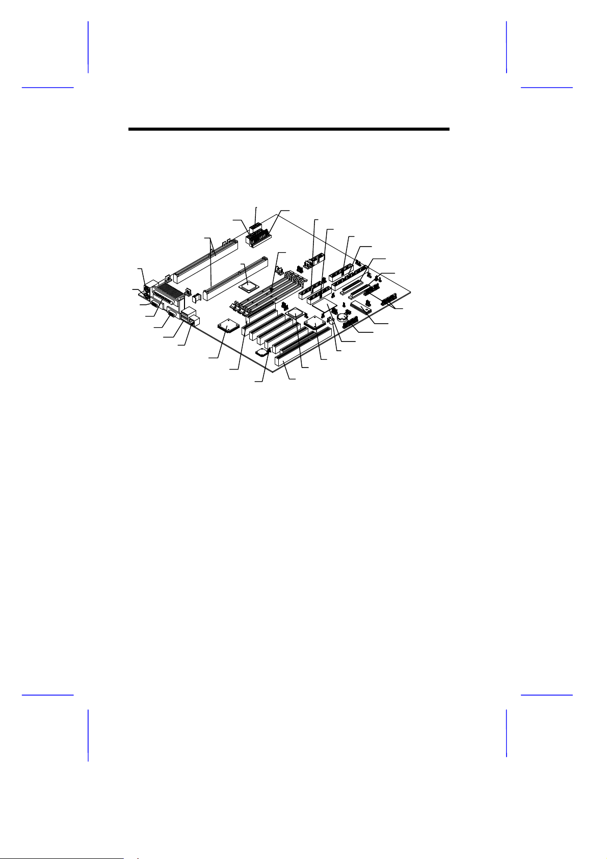
1.3 Layout
1
2
3
4
5
6
1 Mouse port
2 Keyboard port
3 Serial port 2
4 Parallel port
5 Serial port 1
6 USB connector
7 RJ-45
8 LAN controller
9 AGP slot
10 PCI slots
11 ISA slot
12 Intel 82371EB PIIX4E (PCI ISA bridge)
13 DEC 21152 (PCI-PCI bridge)
14 Buzzer
15 SCSI controller
16 Battery
17 System BIOS
18 RDM connectors
19 Channel 1 Ultra-wide/Ultra-2 SCSI
connector (68 pin)
20 Channel 2 Ultra-wide/Ultra-2 SCSI
connector (68 pin)
21 Channel 2 fast/narrow SCSI
connector (50 pin)
22 FDD connector
23 EIDE connector 2 (secondary)
24 EIDE connector 1 (primary)
25 DIMM sockets
26 Intel 443GX system controller
27 Power connector 1
28 Power connector 2
29 Power connector 3
30 Slot 1 CPU sockets
1-4 User’s Guide
Page 5
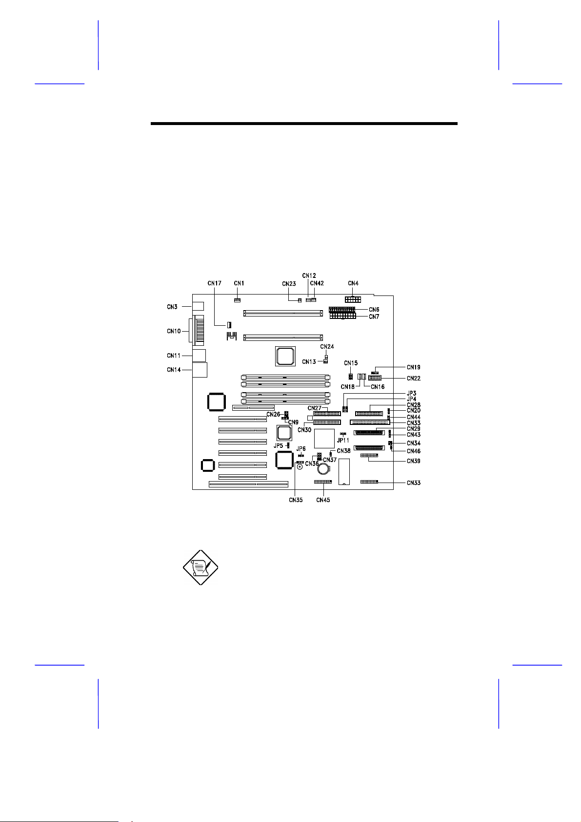
1.4 Jumpers and Connectors
1.4.1 Jumper and Connector Locations
Jumpers are prefixed P”. Connectors are
prefixed N”. The blackened pin of a
jumper or connector represents pin 1.
System Board 1-5
Page 6

1.4.2 Jumper Settings
The table below lists the system board jumpers with their
corresponding settings and functions.
Jumper Setting Function
BIOS Logo
JP3 1-2
Password Security
JP4 1-2
Boot Block Mode
JP5 1-2
Sound Output
JP6 1-2*
SCSI Channel 1Terminator
JP11
AlertPack Select
JP7
*
2-3
2-3*
2-3*
2-3
1-2*
2-3
1-2 / 4-5
2-3 / 5-6*
Logo
OEM
Check password
Bypass password
Disabled
Enabled
Buzzer
Speakers
Enabled
Disabled
AlertPack and LM80
LM80 only
*
Default
1-6 User’s Guide
Page 7

1.4.3 Connector Functions
The table below lists the different connectors on the system board and
their respective functions.
Connector Function
CN1 Cabinet Fan Connector
CN4 337W Power Supply Connector (3.3V and 5V)
CN3 Mouse and Keyboard Ports
CN6 ATX Power Connector
CN7 Power Supply Connector
CN9 Modem Card Ring-in Connector
CN10 Parallel (above), Serial 1(left), and Serial 2 (right)
CN11 USB Connectors
CN12 CPU1 Fan Connector
CN13 CPU2 Fan Connector
CN14 RJ-45 (LAN) Port
CN15 Fail Report LED Connector
CN16 Cabinet Fan Connector
CN17 Cabinet Fan Connector
CN18 Cabinet Fan Connector
CN20 2 Color Power LED Connector
CN22 Redundant Power Status Connector
CN23 CPU1 Temperature Connector
CN24 CPU2 Temperature Connector
CN26 PCI Sound Card Interrupt and DMA Request
CN27 Primary IDE Connector
CN28 FDD Connector
CN29 SCSI Channel 2 Wide Connector
CN30 Secondary IDE Connector
CN31 CD-in connector
CN32 SCSI Channel 1 Wide Connector
ports
Connector
System Board 1-7
Page 8

Connector Function
CN33 SCSI Channel 2 Narrow Connector
CN34 RDM LED Connector
CN35 External Speaker Connector
CN36/CN37 External LED Connector
CN38 Power Switch Connector
CN39/CN47 N.A
CN40 Wake-on-LAN (WOL) Connector
CN42 3-pin Standby Power Connector
CN43 Hard Disk LED Connector
CN44 Reset Button Connector
CN45 Feature Connector (Intel SMM Card)
CN46 Door Switch Connector
CNX19 Backplane board connector (3-pin)
1-8 User’s Guide
Page 9

1.5 ESD Precautions
Always observe the following electrostatic discharge (ESD)
precautions before installing a system component:
1. Do not remove a component from its antistatic packaging until
you are ready to install it.
2. Wear a wrist grounding strap before handling electronic
components. Wrist grounding straps are available at most
electronic component stores.
Do not attempt the procedures described in
the following sections unless you are a
qualified technician.
System Board 1-9
Page 10
1.6 Installing the Pentium II and Pentium III
processors
The following section will briefly explain and illustrate how to install the
Pentium II and Pentium III processors.
You have to attached the fan sink before
installing the processor into the system
board.
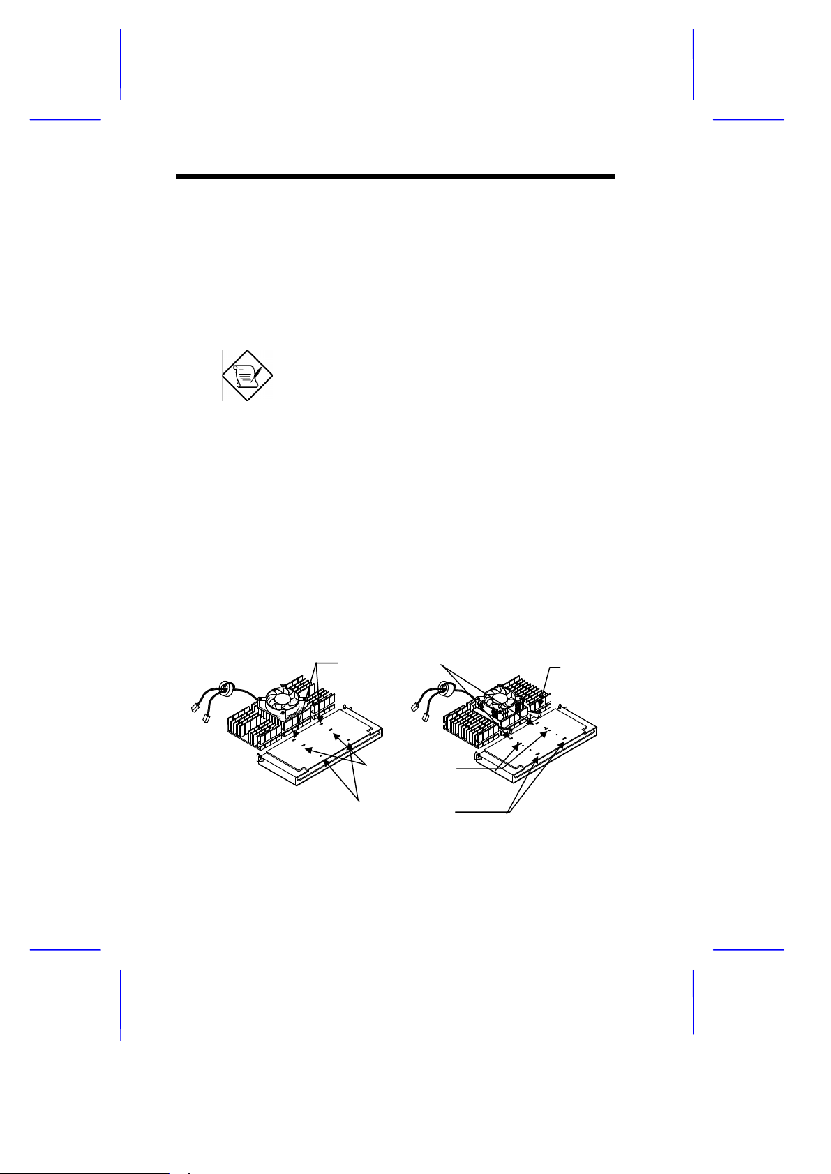
1.6.1 Attaching the Processor Fan Sink
There are currently two kinds of fan sink. Both of them can be easily
attach to the processor module. The new fan sink includes a new
metal retention bracket to hold the processor module more securely.
The processor module comes with holes on one side to hold the clips
of the fan sink. The upper set of holes (near the latches) on the
processor are wider and should match the wider ends of the clips on
the fan sink. The lower set of holes are smaller and should match the
narrow ends of the fan sink clips.
Wide Clip Ends
Wide Holes
Narrow Holes
1-10 User’s Guide
Metal
Retention
bracket
Page 11
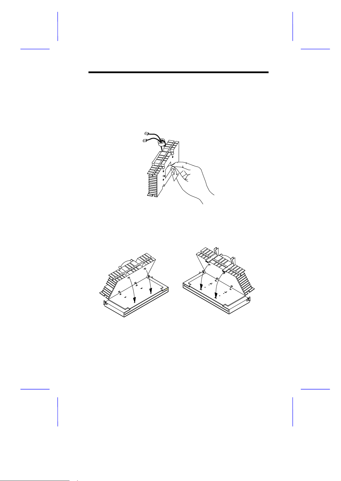
Follow these steps when installing the fan sink and fan into the
processor module:
1. Remove the thermal tape protector at the back of the fan sink.
2. Insert the wide clip ends into the wide holes on the processor and
the narrow clip ends into the narrow holes.
System Board 1-11
Page 12
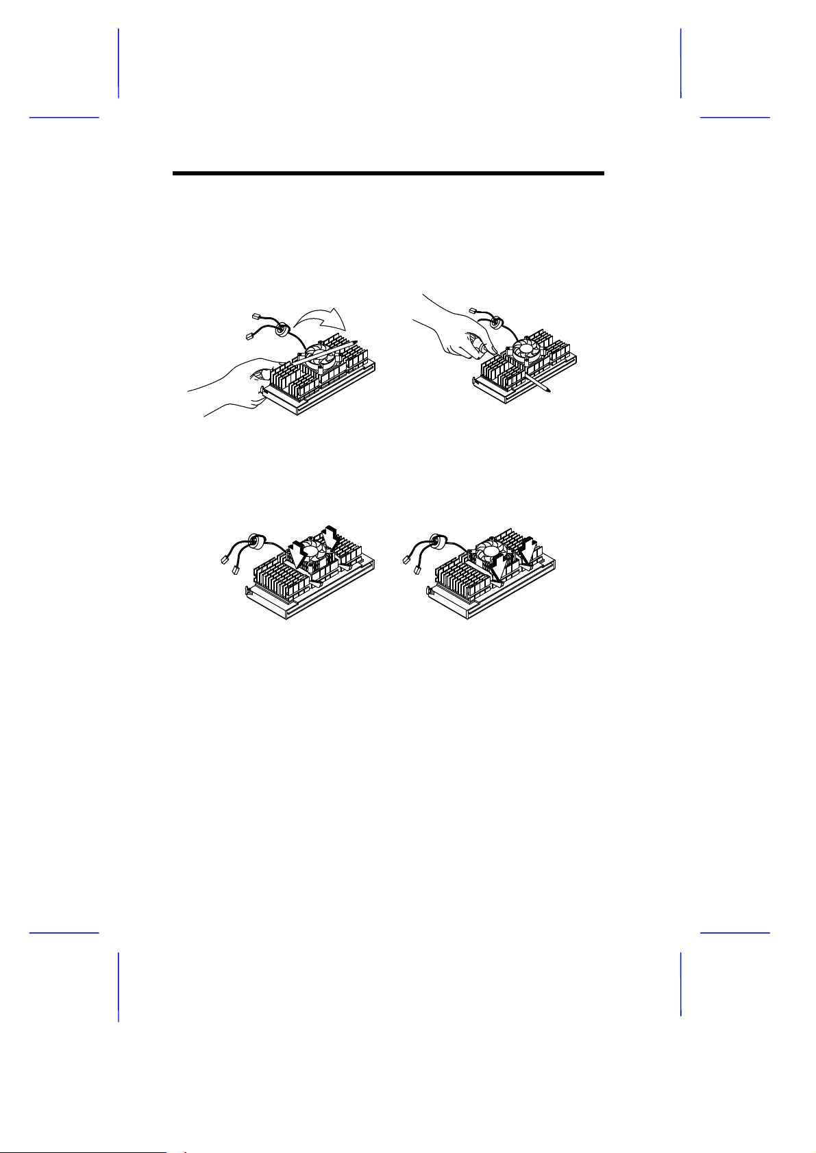
3a. Use a screwdriver to press and lock in the wide end of a clip first.
Then without lifting the screwdriver, point it downward to press
and lock the narrow end of the clip.
3b. Using your fingers, push down the metal bracket until it clicks into
the CPU cartridge and then push the metal bracket handle to
lock the metal bracket into place.
1-12 User’s Guide
Page 13
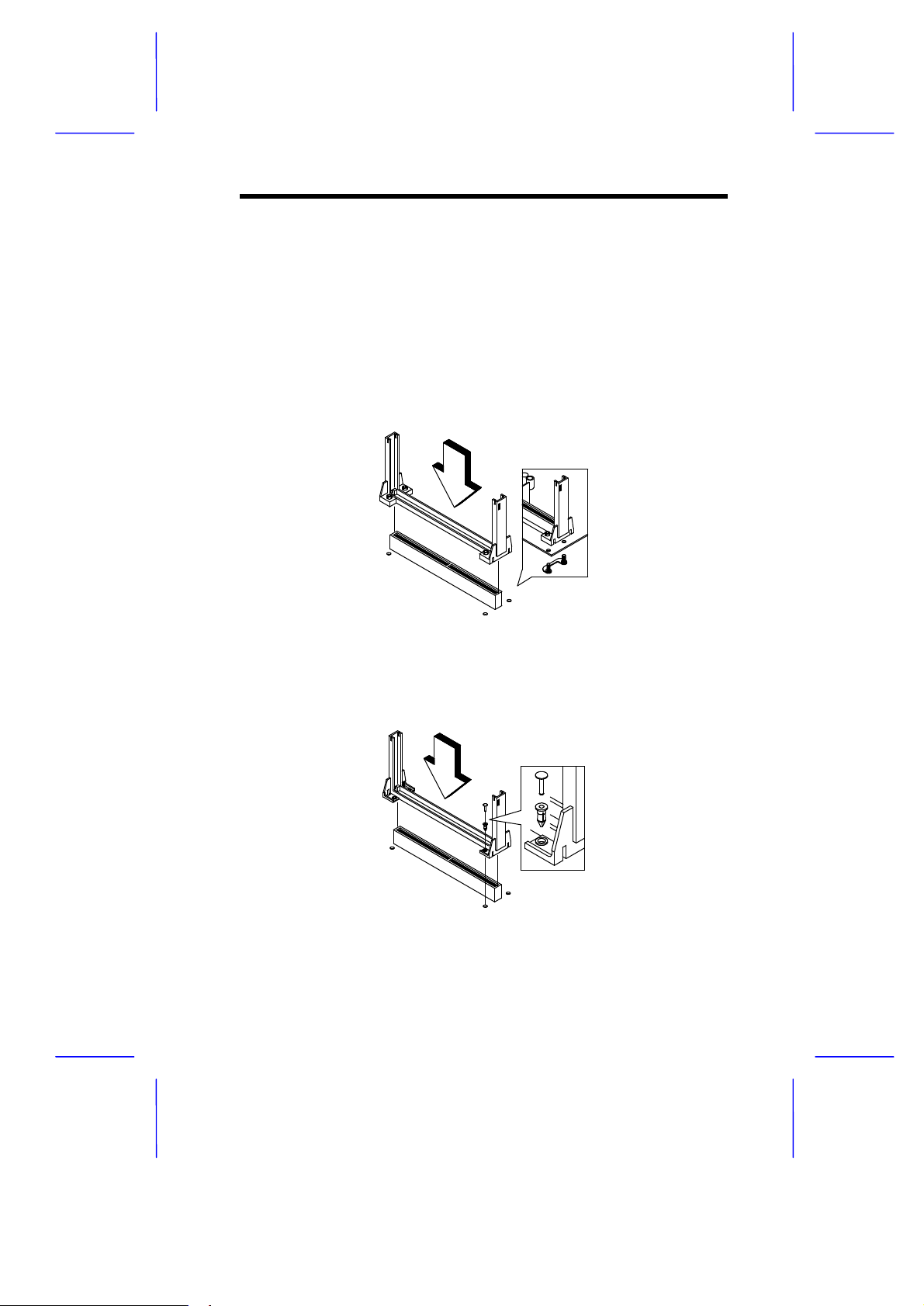
1.6.2 Installing a Pentium II or Pentium III
Processor
Follow these steps to install the processor to the socket on the CPU
board.
1a. Place the retention mechanism over the processor socket on the
CPU board. Secure it with the screws that came with the
package.
1b. Place the retention mechanism over the processor socket on the
CPU board. Secure it with the plastic pegs that came with the
package as shown below.
System Board 1-13
Page 14
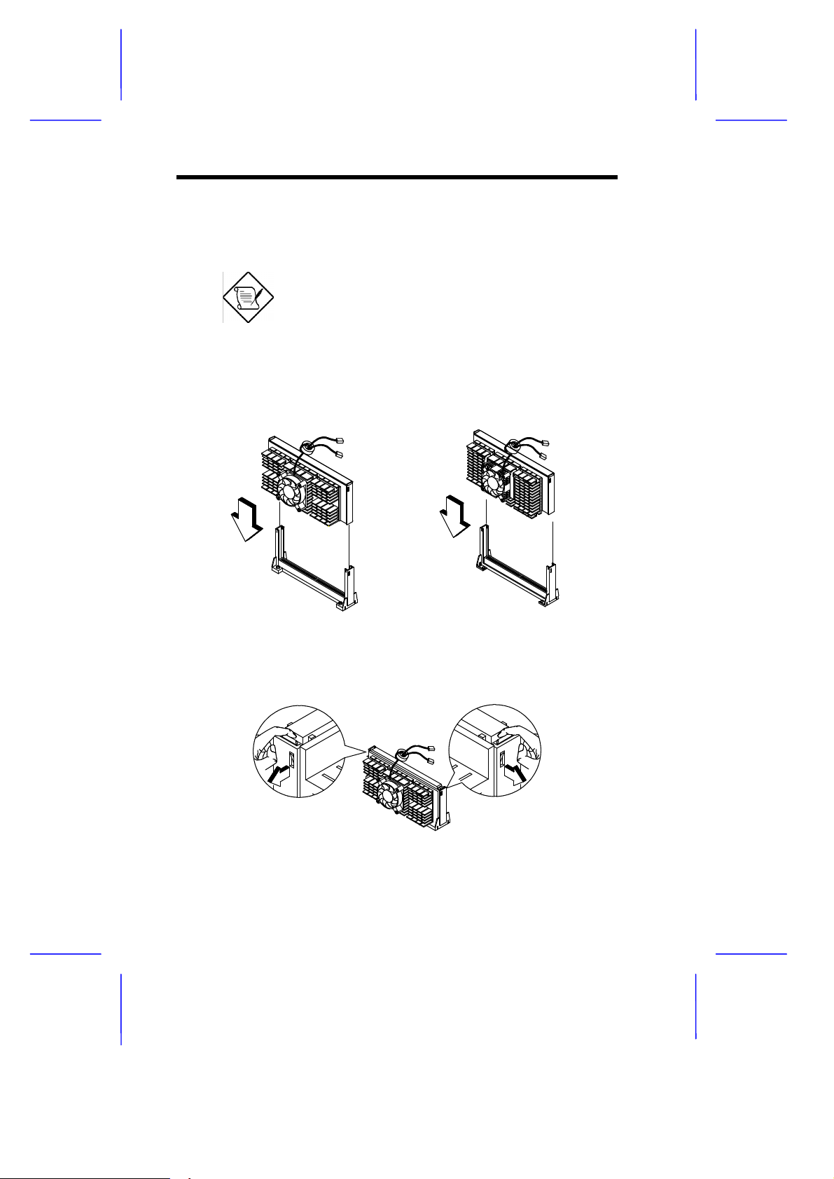
2. With the processor module golden fingers pointing downward,
align the processor to the posts of the retention mechanism then
lower it down.
The golden fingers of the processor module
are slotted such that it only fits in one
direction. Make sure that the module groove
matches the one on the processor socket.
3. Press down the processor module until the golden fingers
completely fit into the socket.
4. Press the latches on the sides to lock the processor module into
place.
1-14 User’s Guide
Page 15
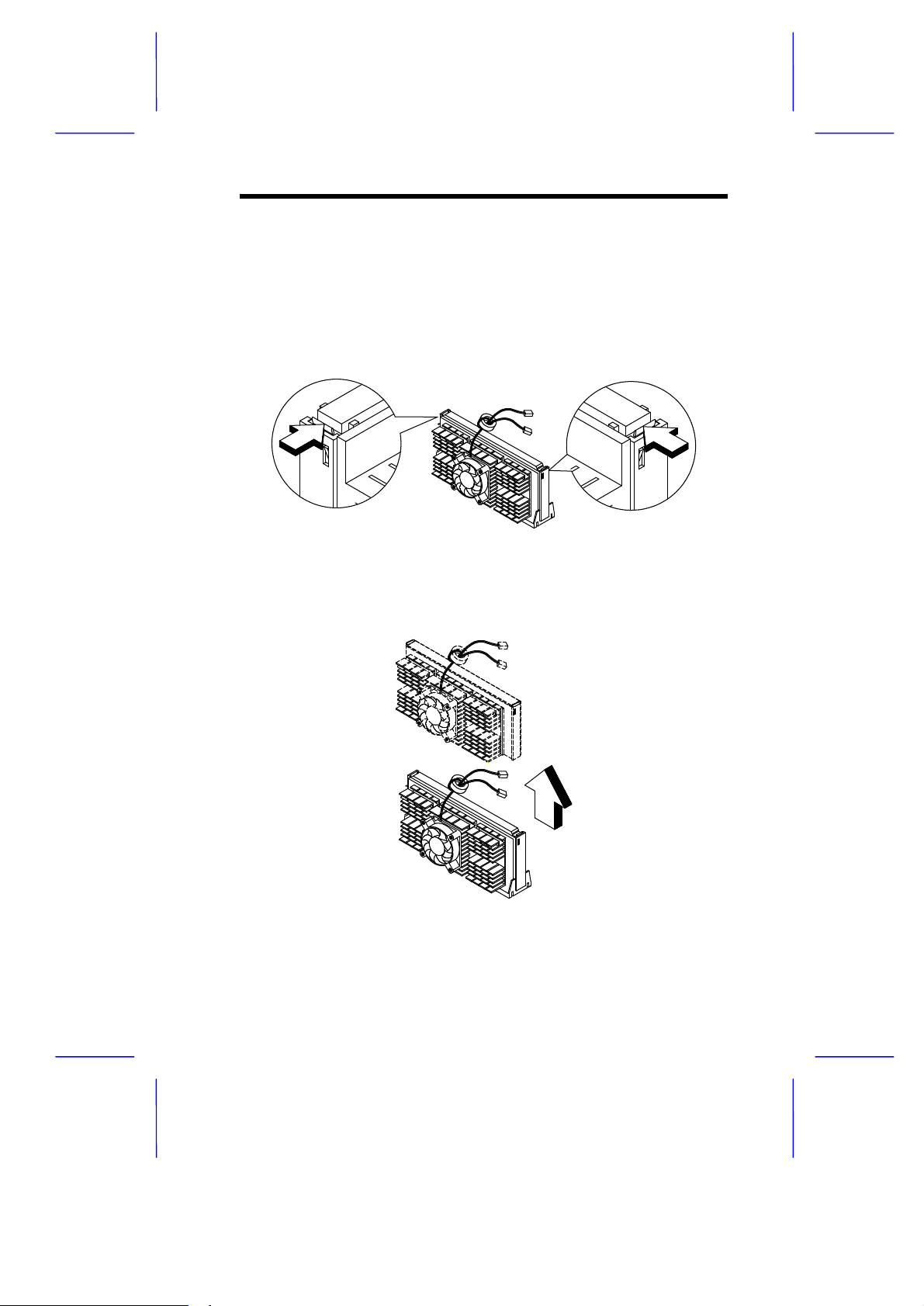
1.6.3 Removing a Pentium II or Pentium III
Processor
Follow these steps to remove the processor module from the CPU
slot.
1. Unlock the latches that secure the processor module.
2. Firmly hold the processor module and pull it out of the socket.
System Board 1-15
Page 16
1.7 Memory Upgrade
The four 168-pin sockets onboard support SDRAM-type DIMMs. You
may install 16-MB, 32-MB, 64-MB, 128-, 256-, or 512-MB (single and
double density) DIMMs for a maximum of 2048-MB system memory.
The SDRAM DIMMs should work under 3.3 volts only; 5 volt memory
devices are not supported. DX6G Plus supports both 100MHz
standard and registered SDRAM. However, please do not use them at
the same time.
Do not use both 66 MHz (unbuffered) and
100 MHz (registered) SDRAM together. This
might cause your system to malfunction.
Each of the sockets represents one independent bank. This allows
you to install DIMMs with different capacities to form a configuration.
1.7.1 Memory Configurations
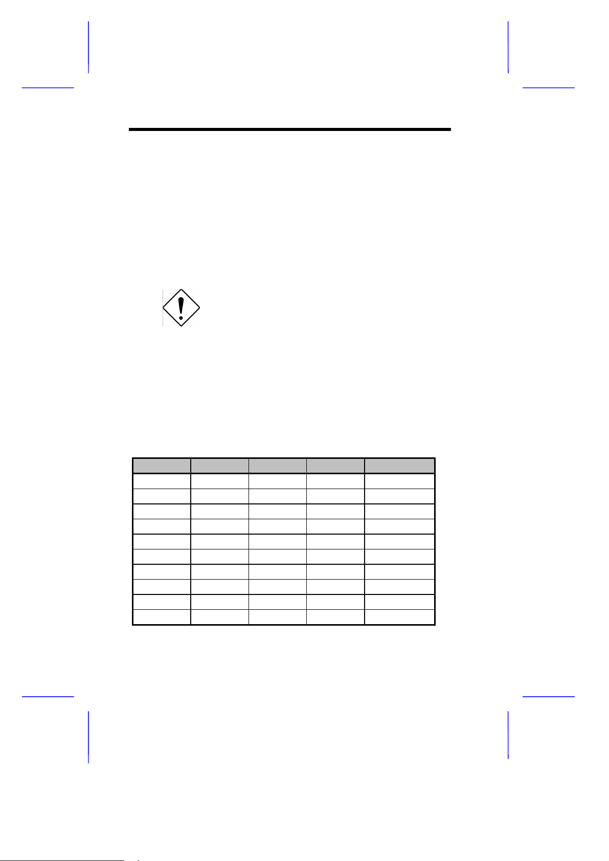
The table below lists some system memory configurations. You may
combine DIMMs with various capacities to form other combinations.
DIMM1 DIMM2 DIMM3 DIMM4 Total Memory
32 MB 32 MB
32 MB 32 MB 64 MB
32 MB 32 MB 32 MB 96 MB
32 MB 32 MB 32 MB 32 MB 128 MB
64 MB 64 MB
64 MB 64 MB 128 MB
64 MB 64 MB 64 MB 192 MB
64 MB 64 MB 64 MB 64 MB 256 MB
128 MB 128 MB
128 MB 128 MB 256 MB
1-16 User’s Guide
Page 17
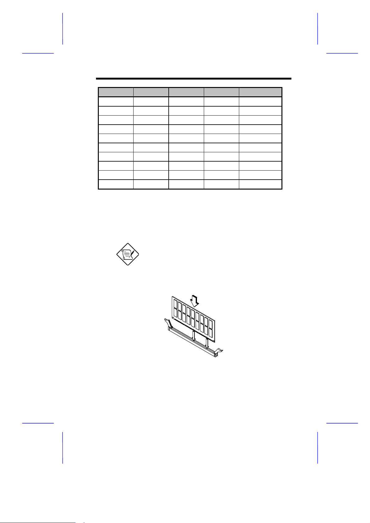
DIMM1 DIMM2 DIMM3 DIMM4 Total Memory
128 MB 128 MB 128 MB 384 MB
128 MB 128 MB 128 MB 128 MB 512 MB
256 MB 256 MB
256 MB 256 MB 512 MB
256 MB 256 MB 256 MB 768 MB
256 MB 256 MB 256 MB 256 MB 1024 MB
512 MB 512 MB
512 MB 512 MB 1024 MB
512 MB 512 MB 512 MB 1536 MB
512 MB 512 MB 512 MB 512 MB 2048 MB
1.7.2 Installing a DIMM
To install a DIMM, align it with the socket and press it down until the
holding clips secure the DIMM in place.
The DIMM socket is slotted to ensure proper
installation. If you slip in a DIMM but it does
not completely fit, you may have inserted it
the wrong way. Reverse the orientation of
the DIMM.
System Board 1-17
Page 18
1.7.3 Removing a DIMM
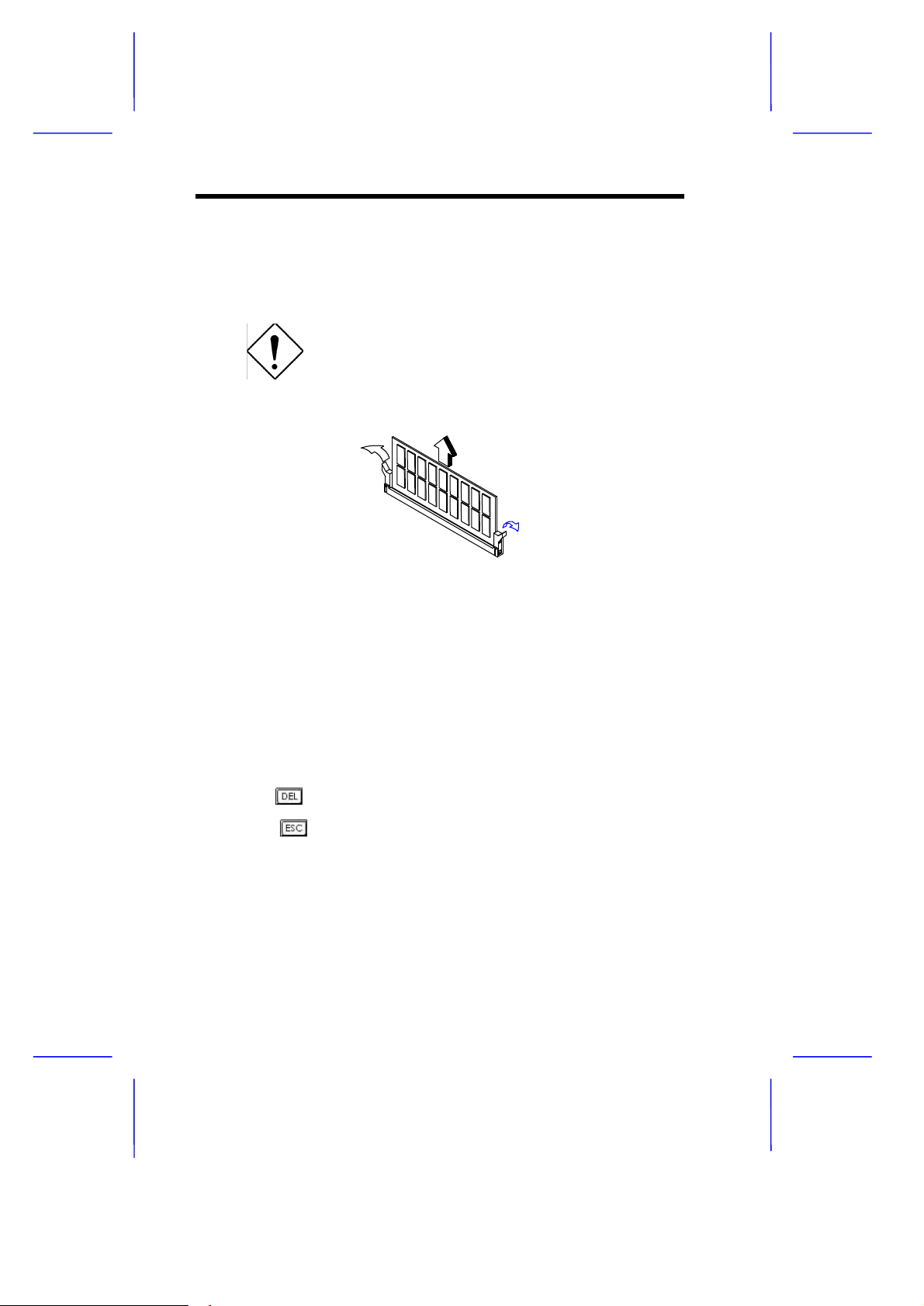
To remove a DIMM, press the holding clips on both sides of the
socket outward to release the DIMM.
Place your forefingers on the top of the
DIMM before you press the holding clips to
gently disengage the DIMM from the socket.
1.7.4 Reconfiguring the System
Reconfigure the system after installing or removing DIMMs.
Follow these steps to reconfigure the system:
1. Reboot the system. A memory error message appears,
indicating that the total memory does not match the value stored
in CMOS.
2. Press .
3. Press twice to exit Setup and reboot the system. The
system boots with the new memory configuration.
1-18 User’s Guide
Page 19
1.8 Installing Expansion Cards
1.8.1 Installing PCI Cards
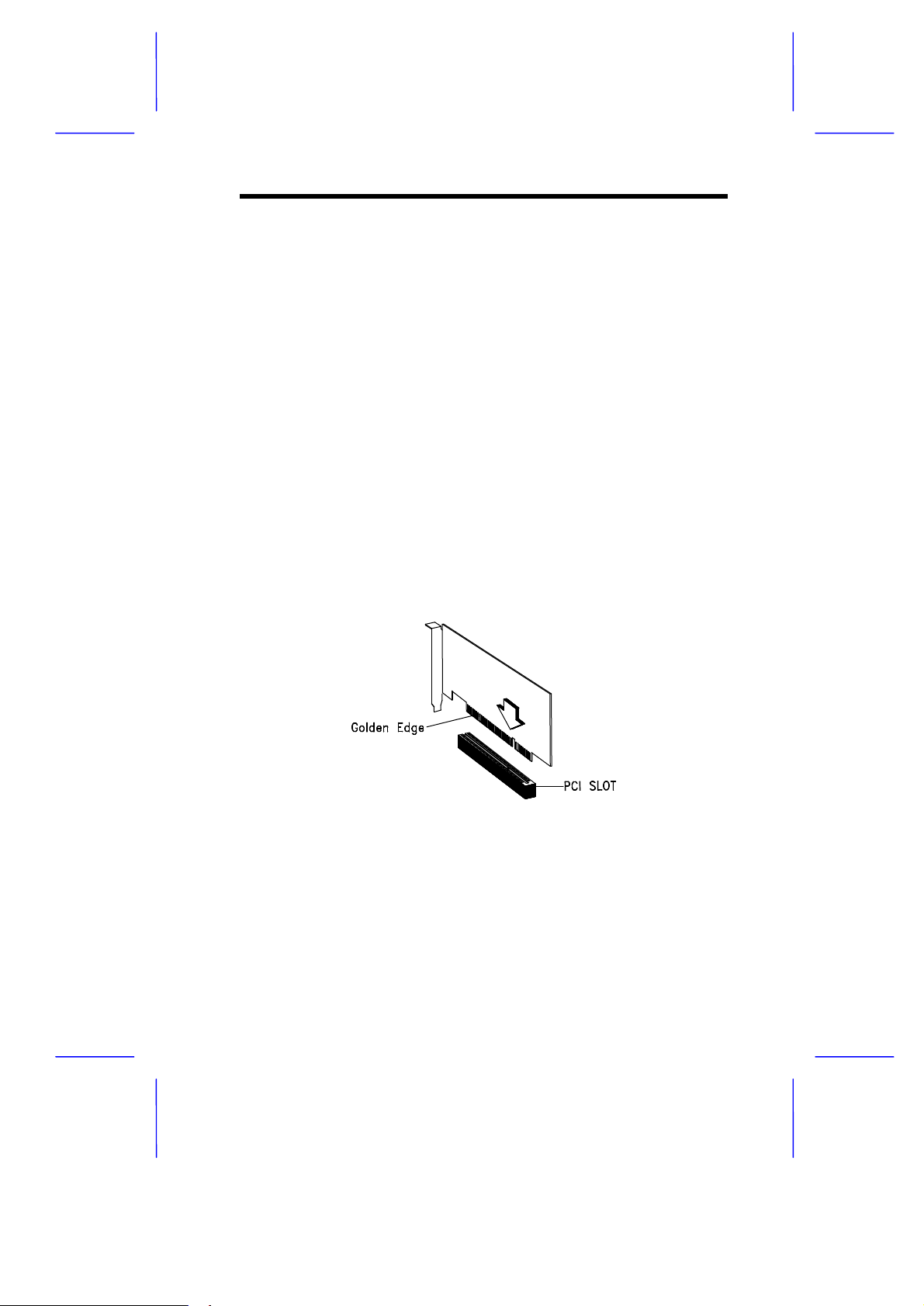
To install PCI cards:
1. Locate the PCI slots on the system board.
2. Remove the bracket on the housing opposite an empty PCI slot.
3. Insert a PCI card into the slot. Make sure that the card is
properly seated.
4. Secure the card to the housing with a screw.
When you turn on the system, BIOS automatically detects and
assigns resources to the PCI devices.
1.8.2 Installing ISA Cards
Both PnP and non-PnP ISA cards require specific IRQs. When
installing ISA cards, make sure that the IRQs required by these cards
are not previously assigned to PCI devices to avoid resource conflicts.
System Board 1-19
Page 20
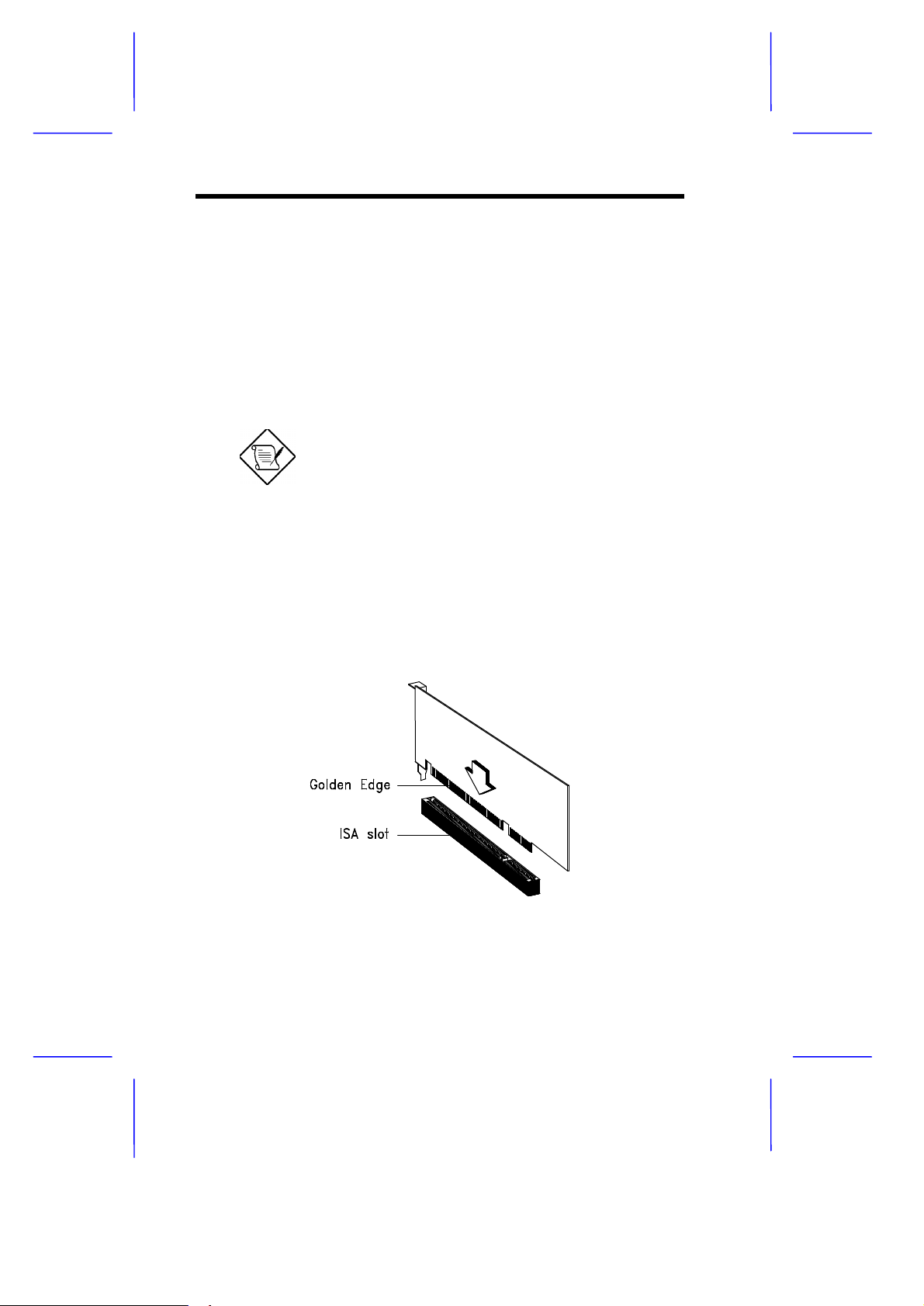
Follow these steps when installing ISA cards:
1. Remove all PnP cards installed in the system, if any.
2. Install non-PnP ISA cards.
3. Turn on the system.
4. Use the operating system or ICU to manually assign the
appropriate IRQs to the cards. This ensures that BIOS will not
use the resources assigned to the non-PnP ISA cards.
BIOS detects and configures only PnP cards.
5. Turn off the system.
6. Locate the expansion slots and install the PnP ISA and PCI
cards.
7. Turn on the system. This time PnP BIOS automatically
configures the PnP ISA and PCI cards with the available
resources.
1-20 User’s Guide
Page 21
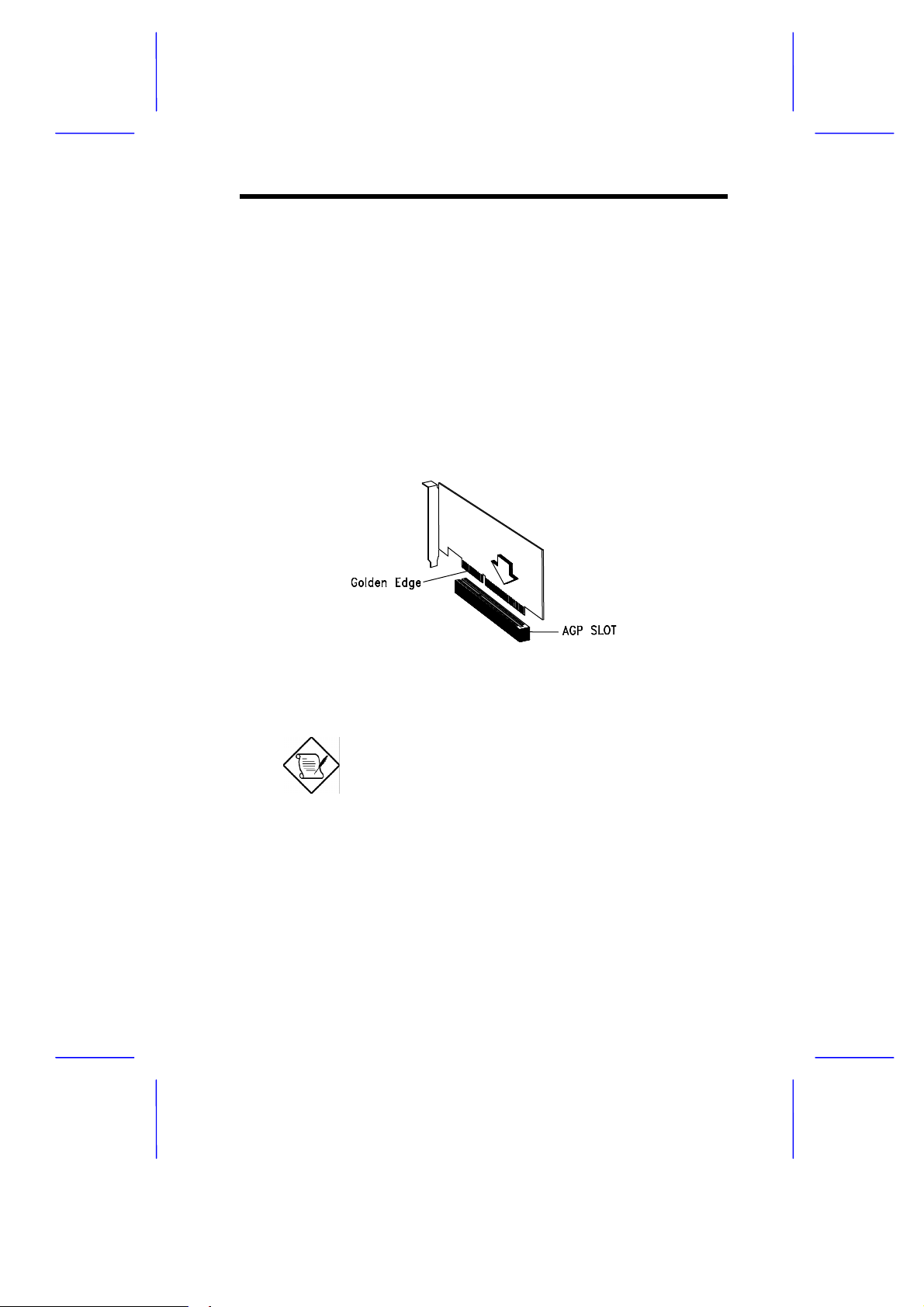
1.8.3 Installing AGP Card
When installing an AGP card, make sure that the IRQ required by the
card is not already assigned to a PCI or ISA device to avoid resource
conflicts.
Follow these steps when installing an AGP card:
1. Locate the AGP slot on the mainboard.
2. Insert an AGP card into the slot. Make sure that the card is
properly seated.
When you turn on the system, BIOS automatically detects and
assigns resources to the AGP device.
BIOS detects and configures only PnP cards.
System Board 1-21
Page 22

1.9 LDCM
Intel® LANDesk® Client Manager Version 3.3 is an application that
simplifies local and network management of mobile and desktop client
systems. It monitors PC health to provide local and remote alerts. It
gives local and remote views of hardware and software component,
even via dial-up. And it does all this through standards and industry
initiatives such as Desktop Management Interface (DMI), Simple
Network Management Protocol (SNMP) and the Wired for
Management (WfM) Initiative.
This release is pre-installed on Original Equipment Manufacturers
(OEMs) PCs and is designed to lower the cost of PC ownership while
providing greater control and flexibility to systems administrators.
Key features
Wired for Management Baseline Version 2.0 compliance.
Remote wake-up
Remote dial-up
Dynamic mobile devices
International languages
Real-time monitoring and alerting of hard drive, memory, fan, power
supply and temperature.
DMI v2.0-based local and remote client management.
SNMP Trap generation for enterprise alerting.
Certificate-based authentication for enhanced security.
Software Development Kit (SDK) for OEM customization.
1-22 User’s Guide
Page 23

1.10 Error Messages
Do not continue using the computer if you receive an error message
of any type. Note the message and take corrective action. This
section explains the different types of error messages and
corresponding corrective measures.
There are two general types of error messages:
• Software
• System
1.10.1 Software Error Messages
Software error messages are returned by your operating system or
application. These messages typically occur after you boot the
operating system or when you run your applications. If you receive
this type of message, consult your application or operating system
manual for help.
1.10.2 System Error Messages
A system error message indicates a problem with the computer itself.
A message of this type normally appears during the power-on selftest, before the operating system prompt appears.
The table below lists possible system error messages.
Message Action
CMOS Battery Error Replace the battery or contact
your dealer.
CMOS Checksum Error Run Setup.
CPU BIOS Update Code
Mismatch
System Board 1-23
Contact your dealer.
Page 24

Message Action
Diskette Drive Controller Error
or Not Installed
Diskette Drive Error Check the CMOS settings in
Diskette Drive A Type
Mismatch
Diskette Drive B Type
Mismatch
Equipment Configuration Error Modify DRAM configuration to
Hard Disk Controller Error Run Setup.
Hard Disk 0 Error Check all cable connections.
Hard Disk 1 Error Check all cable connections.
Hard Disk 0 Extended Type
Error
Hard Disk 1 Extended Type
Error
I/O Parity Error Contact your dealer.
Keyboard Error or No
Keyboard Connected
Keyboard Interface Error Replace the keyboard or contact
Memory Error at:
MMMM:SSSS:OOO
(W:XXXX, R:YYYY)
where:
M: MB, S: Segment,
O: Offset,
X/Y: write/read pattern
Check and connect the control
cable to the diskette controller.
Setup and the diskette drive cable
connections.
Run Setup and select the proper
drive type.
Run Setup and select the proper
drive type.
agree with one of the options in
Table 1-3.
Replace hard disk.
Replace hard disk.
Run Setup.
Run Setup.
Check and connect the keyboard
to the system unit.
your dealer.
Check DIMMs on the system
board. Contact your dealer.
1-24 User’s Guide
Page 25
Message Action
Memory Size Mismatch
CPU Clock Mismatch
Onboard Serial Port 1 Conflict Run Setup and disable the port.
Onboard Serial Port 2 Conflict Run Setup and disable the port.
Onboard Parallel Port Conflict Run Setup and disable the port.
Pointing Device Error Check and connect pointing
Pointing Device Interface Error Replace the pointing device or
Press F1 key to continue or
Del for Setup
Real Time Clock Error Run Setup and set the time and
Press Esc to turn off NMI, any
key to reboot
Check the memory size based on
the system specifications. Check
the internal cable connections. If
you are sure that connections and
values are correct, ignore the
message. If the message
reappears, ask for technical
assistance.
device.
contact your dealer.
Press or
to enter Setup.
date.
Press to disregard the NMI
error.
Press any other key to reboot the
system.
System Board 1-25
Page 26

1.10.3 Correcting Error Conditions
As a general rule, if an error message says "Press F1 to continue," it
is caused by a configuration problem, which can be easily corrected.
An equipment malfunction is more likely to cause a fatal error, i.e., an
error that causes complete system failure.
Here are some corrective measures for error conditions:
1. Run Setup. You must know the correct configuration values for
your system before you enter Setup, which is why you should
write them down when the system is correctly configured. An
incorrect configuration is a major cause of power-on error
messages, especially for a new system.
2. Remove the system unit cover. Check that the jumpers on the
system board and any expansion boards are set correctly.
3. If you cannot access a new disk, it may be because your disk is
not properly formatted. Format the disk first using the FDISK and
FORMAT commands.
4. Check that all connectors and boards are securely plugged in.
If you go through the corrective steps above and still receive an error
message, the cause may be an equipment malfunction.
If you are sure that your configuration values are correct and your
battery is in good condition, the problem may lie in a damaged or
defective chip.
In either case, contact an authorized service center for assistance.
1-26 User’s Guide
Page 27

C h a p t e r
2
Setup Utility
Most systems are already configured by the manufacturer or the
dealer. There is no need to run Setup when starting the computer
unless you get a Run Setup message.
The Setup program loads configuration values into the battery-backed
nonvolatile memory called CMOS RAM. This memory area is not part
of the system RAM.
If you repeatedly receive Run Setup
messages, the battery may be bad. In this
case, the system cannot retain configuration
values in CMOS. Ask a qualified technician
for assistance.
Before you run Setup, make sure that you have saved all open files.
The system reboots immediately after you exit Setup.
Setup Utility 2-1
Page 28

2.1 Entering Setup
To enter Setup, simultaneously press the key .
You must press . while the system is
booting. This key combination does not work
during any other time.
The Setup Utility Main Menu appears:
Setup Utility
• System Information
• Product Information
• Disk Drives
• Onboard Peripherals
• Power Management
• Boot Options
• Date and Time
• System Security
• System Event Log
• Advanced Options
Abort Settings Change
Load Default Settings
The system supports two BIOS Utility levels: Basic and Advanced.
Basic function: PnP/PCI Options
Advanced functions: Memory/Cache Options
CPU Frequency
2-2 User’s Guide
Page 29

If you are an advanced user, you may want to check the detailed
configuration of your system. Detailed system configurations are
contained in the Advanced Level. To view the Advanced Level, press
.
The asterisk (*) mark indicates that the parameter
appears only when you are in the Advanced
Level.
The parameters on the screens show default
values. These values may not be the same as
those in your system.
The grayed items on the screens have fixed
settings and are not user-configurable.
Use the arrow keys , to move around the Setup Utility screen.
Press to return to the Main menu.
2.2 System Information
The following screen appears if you select System Information from
the Main menu:
Setup Utility 2-3
Page 30

System Information
Processor .......................... Pentium II
Processor Speed..................... 400 MHz
Internal Cache...................... 32 KB, Enabled
External Cache...................... 512 KB, Enabled
Diskette Drive A.................... 1.44 MB, 3.5-inch
Diskette Drive B.................... None
IDE Primary Channel Master .......... Hard Disk, xxx MB
IDE Primary Channel Slave ........... None
IDE Secondary Channel Master........ None
IDE Secondary Channel Slave ........ None
Total Memory........................ xxx MB
1st Bank.......................... SDRAM, xxx MB
2nd Bank.......................... None
3rd Bank ......................... None
4th Bank ......................... None
The System Information menu shows the current basic configuration
of your system.
The next screen shows page 2 of the System Information menu.
System Information
Serial Port 1...................... 3F8h, IRQ 4
Serial Port 2...................... 2F8h, IRQ 3
Parallel Port...................... 378h, IRQ 7
PS/2 Mouse......................... Installed
The sections below explain the parameters.
2-4 User’s Guide
Page 31

2.2.1 Processor
The Processor parameter specifies the type of processor currently
installed in your system. The system supports Intel Pentium II and
Pentium III processors.
2.2.2 Processor Speed
The Processor Speed parameter specifies the speed of the processor
currently installed in your system.
2.2.3 Internal Cache
This parameter specifies the first-level or the internal memory (i.e., the
memory integrated into the CPU) size, and whether it is enabled or
disabled.
2.2.4 External Cache
This parameter specifies the second-level cache memory size
currently supported by the system. The available cache sizes are 512
KB.
2.2.5 Diskette Drive A
This parameter specifies the system current diskette drive A
settings.
2.2.6 Diskette Drive B
This parameter specifies the system current diskette drive B
settings.
Setup Utility 2-5
Page 32

2.2.7 IDE Primary Channel Master
This parameter specifies the current configuration of the IDE device
connected to the master port of the primary IDE channel.
2.2.8 IDE Primary Channel Slave
This parameter specifies the current configuration of the IDE device
connected to the slave port of the primary IDE channel.
2.2.9 IDE Secondary Channel Master
This parameter specifies the current configuration of the IDE device
connected to the master port of the secondary IDE channel.
2.2.10 IDE Secondary Channel Slave
This parameter specifies the current configuration of the IDE device
connected to the slave port of the secondary IDE channel.
2.2.11 Total Memory
This parameter specifies the total amount of onboard memory. The
memory size is automatically detected by BIOS during the POST. If
you install additional memory, the system automatically adjusts this
parameter to display the new memory size.
1st Bank/2nd Bank/3rd Bank/4th Bank
The 1st Bank, 2nd Bank, 3rd Bank, and 4th Bank parameters indicate
the type and size of DRAM installed in DIMM sockets 1, 2, 3, and 4
respectively. The None setting indicates that there is no DRAM
installed. For the location of the DIMM sockets, refer to section 1.3 or
1.4.
2-6 User’s Guide
Page 33

2.2.12 Serial Port 1
This parameter shows the serial port 1 address and IRQ setting.
2.2.13 Serial Port 2
This parameter shows the serial port 2 address and IRQ setting.
2.2.14 Parallel Port
This parameter shows the parallel port address and IRQ setting.
2.2.15 PS/2 Mouse
The BIOS utility automatically detects if there is a pointing device
connected to your system. If there is, this parameter displays the
Installed setting. Otherwise, this is set to None.
Setup Utility 2-7
Page 34

2.3 Product Information
The Product Information contains the general data about the system,
such as the product name, serial number, BIOS version, etc. This
information is necessary for troubleshooting (may be required when
asking for technical support).
The following shows how the Product Information screen appears:
Product Information
Product Name........................... DX6G Plus
System S/N............................. xxxxxxxxx
Main Board ID.......................... DX6G PLUS
Main Board S/N ........................ N/A
System BIOS Version.................... v3.1 R0.01
SMBIOS Version......................... 2.1
System BIOS ID......................... R0.01
BIOS Release Date...................... Jun 02’99
2.3.1 Product Name
This parameter specifies the official name of the system.
2.3.2 System S/N
This parameter specifies the system serial number.
2.3.3 Main Board ID
This parameter specifies the system board identification number.
2-8 User’s Guide
Page 35

2.3.4 Main Board S/N
This parameter specifies the system board serial number.
2.3.5 System BIOS Version
This parameter specifies the version of the BIOS utility.
2.3.6 SMBIOS Version
This parameter specifies the version of the SMBIOS version.
2.3.7 System BIOS ID
This parameter specifies AOpen BIOS ID.
2.3.8 BIOS Release Date
This parameter specifies the BIOS release date.
Setup Utility 2-9
Page 36

2.4 Disk Drives
Select Disk Drives to input configuration values for disk drives.
The following screen shows the Disk Drives menu:
Disk Drives
Diskette Drive A....................... [xx-MB, xx-inch]
Diskette Drive B....................... [ None ]
LS-120 Drive as........................ [ Normal ]
• IDE Primary Channel Master
• IDE Primary Channel Slave
• IDE Secondary Channel Master
• IDE Secondary Channel Slave
2.4.1 Floppy Drives
To enter the configuration value for the first floppy drive (drive ),
highlight the Floppy Drive A parameter. Press or key to view
the options and select the appropriate value.
Possible settings for the Floppy Drive parameters are:
• [ None ]
• [360 KB, 5.25-inch]
• [1.2 MB, 5.25-inch]
• [720 KB, 3.5-inch]
• [1.44 MB, 3.5-inch]
• [2.88 MB, 3.5-inch]
2-10 User’s Guide
Page 37

Follow the same procedure to configure floppy drive . Choose None
if you do not have a second floppy drive.
2.4.2 LS-120 Drive As
This parameter allows you not only to enable the LS-120 device
installed in your system, but also to specify the function of the device.
The setting affects how BIOS will detect the device.
Possible settings are:
• Normal In this setting, BIOS does not support the LS-120
drive. The drive needs the LS-120 device driver to operate.
• Drive A BIOS recognizes the LS-120 drive as drive A. If a
standard diskette drive A exists, BIOS automatically identifies it
as drive B. If a standard diskette drive B exists, it automatically
becomes inaccessible.
If two LS-120 drives exist, BIOS recognizes them as drive A and
drive B, respectively.
• Drive B BIOS recognizes the LS-120 drive as drive B. If a
standard diskette drive B exists, it becomes inaccessible.
• Hard Disk BIOS recognizes the LS-120 drive as a hard disk.
In this setting, format the LS-120 drive as any other hard disk and
assign it a drive letter C, D, E, and so on. See the documentation
that came with the LS-120 drive for more information.
2.4.3 IDE Drives
To configure the IDE drives connected to your system, select the
parameter that represents the channel and port where the desired
hard disk to configure is connected. The options are:
Setup Utility 2-11
Page 38

IDE Primary Channel Master
This parameter lets you configure the hard disk drive connected to the
master port of IDE channel 1.
IDE Primary Channel Slave
This parameter lets you configure the hard disk drive connected to the
slave port of IDE channel 1.
IDE Secondary Channel Master
This parameter lets you configure the hard disk drive connected to the
master port of IDE channel 2.
IDE Secondary Channel Slave
This parameter lets you configure the hard disk drive connected to the
slave port of IDE channel 2.
The following screen appears if you select any of the IDE Drive
parameters:
IDE Primary/Secondary
Channel Master/Slave
Type ........................... [ Auto ]
Cylinder ..................... [ XXXX ]
Head ......................... [ XXXX ]
Sector ....................... [ XXXX ]
Size ......................... [ XXXX ] MB
Hard Disk Size > 504MB ......... [ Auto ]
*Hard Disk Block Mode ........... [ Auto ]
*Advanced PIO Mode .............. [ Auto ]
*Hard Disk 32-bit Access ........ [Enabled ]
*DMA Transfer Mode .............. [Auto]
2-12 User’s Guide
Page 39

The above parameters marked with ‘*’ will only
appear if you access the advanced level option in
the Main Menu. Please refer to section 2.1 for
more information.
TYPE
This parameter lets you specify the type of hard disk installed in your
system. If you want BIOS to automatically configure your hard disk,
select Auto. If you know your hard disk type, you can enter the
setting manually.
Setting this parameter also sets the Cylinder, Head, Sector, and Size
parameters.
CYLINDERS
This parameter specifies the number of cylinders of your hard disk,
and is automatically set depending on your Type parameter setting.
HEADS
This parameter specifies the number of heads of your hard disk, and
is automatically set depending on your Type parameter setting.
SECTORS
This parameter specifies the number of sectors of your hard disk, and
is automatically set depending on your Type parameter setting.
SIZE
This parameter specifies the size of your hard disk, in MB.
Setup Utility 2-13
Page 40

Enhanced IDE Features
HARD DISK SIZE > 504 MB
When set to Auto, the BIOS utility automatically detects if the installed
hard disk supports the function. If supported, it allows you to use a
hard disk with a capacity of more than 504 B. This is made possible
through the Logical Block Address (LBA) mode translation. However,
this enhanced IDE feature works only under DOS, Windows 3.x,
Windows 95, and Windows NT 3.5 and above. Other operating
systems require this parameter to be set to Disabled.
HARD DISK BLOCK MODE
This function enhances disk performance depending on the hard disk
in use. If you set this parameter to Auto, the BIOS utility automatically
detects if the installed hard disk drive supports the Block Mode
function. If supported, it allows data transfer in blocks (multiple
sectors) at a rate of 256 bytes per cycle. To disregard the feature,
change the setting to Disabled.
ADVANCED PIO MODE
When set to Auto, the BIOS utility automatically detects if the installed
hard disk supports the function. If supported, it allows for faster data
recovery and read/write timing that reduces hard disk activity time.
This results in better hard disk performance. To disregard the feature,
change the setting to Disabled.
HARD DISK 32-BIT ACCESS
Enabling this parameter improves system performance by allowing
the use of the 32-bit hard disk access. This enhanced IDE feature
works only under DOS, Windows 3.x, Windows 95, Windows NT, and
Novell NetWare. If your software or hard disk does not support this
function, set this parameter to Disabled .
2-14 User’s Guide
Page 41

DMA TRANSFER MODE
The Ultra DMA and Multi-DMA modes enhance hard disk
performance by increasing the transfer rate. However, besides
enabling these features in the BIOS Setup, both the Ultra DMA and
Multi-DMA modes require the DMA driver to be loaded. By setting this
parameter to Auto, BIOS automatically sets the appropriate DMA
mode for your hard disk.
Setup Utility 2-15
Page 42

2.5 Onboard Peripherals
The Onboard Peripheral Configuration allows you to configure the
onboard communication ports and the onboard devices. Selecting
this option displays the following screen:
Onboard Peripherals
Serial Port 1....................... [Enabled ]
Base Address..................... [3F8h]
IRQ.............................. [4]
Serial Port 2....................... [Enabled ]
Base Address..................... [2F8h]
IRQ.............................. [3]
Parallel Port....................... [Enabled ]
Base Address..................... [378h]
IRQ.............................. [7]
Operation Mode................... [Standard]
ECP DMA Channel................ [-]
•Onboard Device Settings
2.5.1 Serial Ports 1 and 2
These parameters allow you to enable or disable serial ports 1 and 2.
Base Address
This function lets you set a logical base address for serial ports 1 and
2. The options are:
• 3F8h • 2F8h • 3E8h • 2E8h
2-16 User’s Guide
Page 43

IRQ
This function lets you assign an interrupt for serial ports 1 and 2. The
options for serial ports 1 are IRQ 4 and 11. The options for serial port
2 are IRQ 3 and 10.
The Base Address and IRQ parameters for
each port are configurable only if the port is
enabled.
2.5.2 Parallel Port
This parameter allows you to enable or disable the parallel port.
Base Address
This function lets you set a logical base address for the parallel port.
The options are:
• 3BCh • 378h • 278h
IRQ
This function lets you assign an interrupt for the parallel port. The
options are IRQ 5 and 7.
The Base Address and IRQ parameters are
configurable only if Parallel Port is enabled.
If you install an add-on card that has a parallel
port whose address conflicts with the onboard
parallel port, a warning appears on the screen.
Check the parallel port address of the add-on
card and change the address to one that does
not conflict.
Setup Utility 2-17
Page 44

Operation Mode
This item allows you to set the operation mode of the parallel port.
The table below lists the different operation modes.
Setting Function
Standard Parallel Port
(Standard)
Standard and Bidirectional
(Bidirectional)
Enhanced Parallel Port
(EPP)
Extended Capabilities Port
(ECP)
ECP DMA CHANNEL
Allows normal speed one-way
operation
Allows normal speed operation in a
two-way mode
Allows bidirectional parallel port
operation at maximum speed
Allows parallel port to operate in
bidirectional mode and at a speed
higher than the maximum data
transfer rate
This item becomes active only if you select Extended Capabilities
Port (ECP) as the operation mode. It allows you to assign DMA
channel 1 or DMA channel 3 for the ECP parallel port function (as
required in Windows 95).
2.5.3 Onboard Device Settings
The Onboard Device Settings menu allows you to configure the
onboard communication ports and the onboard devices. Selecting
this option from the Onboard Peripherals menu displays the following
screen:
2-18 User’s Guide
Page 45

Onboard Device Settings
Floppy Disk Controller.............. [Enabled ]
IDE Controller...................... [Both ]
PS/2 Mouse Controller............... [Enabled ]
USB Host Controller................. [Enabled ]
USB Legacy Mode................... [Disabled]
Onboard SCSI........................ [Enabled ]
Boot from SCSI Device............. [Enabled ]
SMBus Interrupt(IRQ9)............... [Disabled]
Onboard Ethernet Chip............... [Enabled ]
Alert on LAN........................ [Disabled]
Floppy Disk Controller
This parameter lets you enable or disable the onboard floppy disk
controller.
IDE Controller
Set this parameter to Primary to enable only the primary IDE
controller; Both to enable both primary and secondary IDE
controllers; or Disabled to disable all IDE controllers.
PS/2 Mouse Controller
This parameter enables or disables the onboard PS/2 mouse
controller.
USB Host Controller
This parameter lets you enable or disable the USB controller on
board. When enabled, it activates the USB function of the system.
When disabled, it deactivates the function.
Setup Utility 2-19
Page 46

USB LEGACY MODE
This function, when enabled, lets you use a USB keyboard in DOS.
Set this to Disabled to deactivate the USB keyboard function in DOS.
Onboard SCSI Device
This parameter lets you enable or disable the SCSI controller on
board. When enabled, it activates the SCSI function of the system.
When disabled, it also deactivates the function.
BOOT FROM ONBOARD SCSI DEVICE
When set to Enabled, the system checks for a bootable SCSI device.
If a SCSI device is present, the system boots from that device;
otherwise, it boots from the drive specified in the System Boot Drive
parameter. When set to Disabled, the system boots from the drive
specified in the System Boot Drive parameter.
SMBus Interrupt (IRQ9)
The System Management Bus (SMBus) is used for controlling and
getting information from devices on a motherboard. It was designed
for hybrid devices based on analog semiconductor technologies and
with limited digital capabilities. This parameter allows you to enable or
disable this feature.
Onboard Ethernet Chip
This parameter allows you to enable or disable the onboard network
feature.
Alert on LAN
This function is disabled.
2-20 User’s Guide
Page 47

2.6 Power Management
The Power Management menu allows you to configure the system
power-management feature.
The following screen shows the Power Management parameters and
their default settings:
Power Management
Power Management Mode................. [Enabled]
IDE Hard Disk Standby Timer......... [Off]
System Sleep Timer.................. [Off]
Sleep Mode........................ [----]
Power Switch < 4 sec. ................ [Suspend]
System Wake-up Event
Modem Ring Indicator................ [Disabled]
2.6.1 Power Management Mode
This parameter allows you to reduce power consumption. When this
parameter is set to Enabled, you can configure the IDE hard disk and
system timers. Setting it to Disabled deactivates the
power-management feature and its timers.
IDE Hard Disk Standby Timer
This parameter allows the hard disk to enter standby mode after
inactivity of 1 to 15 minutes, depending on your setting. When you
access the hard disk again, allow 3 to 5 seconds (depending on the
hard disk) for the disk to return to normal speed. Set this parameter to
OFF if your hard disk does not support this function.
Setup Utility 2-21
Page 48

System Sleep Timer
This parameter sets the system to the lowest power-saving mode
after a specified period of inactivity. Any keyboard or mouse action or
any activity detected from the IRQ channels resumes system
operation.
SLEEP MODE
This parameter lets you specify the power-saving mode that the
system will enter after a specified period of inactivity. The options are
Standby and Suspend modes.
This parameter becomes configurable only if the System Sleep Timer
is enabled. Any keyboard or mouse action, or any enabled monitored
activities occurring through the IRQ channels resume system
operation.
2.6.2 Power Switch < 4 sec.
When set to Power Off,the system automatically turns off when the
power switch is pressed for less than 4 seconds. When set to
Suspend, the system enters the suspend mode when pressed for less
than 4 seconds.
2.6.3 System Wake-up Event
The system wake-up event allows the system to resume operation
when the modem ring indicator is enabled.
Modem Ring Indicator
When Enabled, any fax/modem activity wakes up the system from
suspend mode. The default setting is Disabled.
2-22 User’s Guide
Page 49

2.6.4 Boot Options
This option allows you to specify your preferred setting for bootup.
The following screen appears if you select Boot Options from the
Basic Configuration menu:
Boot Options
Boot Sequence
1st [Floppy Disk]
2nd [Hard Disk ]
3rd [IDE CD-ROM ]
4th [LANDesk Service Agent]
First Hard Disk Drive................. [SCSI]
Fast Boot............................. [Auto]
Silent Boot........................... [Enabled]
Num Lock After Boot................... [Enabled]
Memory Test........................... [Disabled]
Release All Blocked Memory............ [Enabled]
*Configuration Table................... [Enabled]
Boot from LanDesk Service Agent....... [Disabled]
The above parameter marked with ‘*’ will only
appear if you access the advanced level option in
the Main Menu. Please refer to section 2.1 for
more information.
2.6.5 Boot Sequence
This parameter allows you to specify the boot search sequence during
POST.
st
• 1
Setup Utility 2-23
. The system checks this drive first.
Page 50

nd
• 2
• 3
• 4
BIOS will display an error message if the drive(s) specified is not
bootable.
. The system then checks this drive if it can not boot from the
1st specified drive.
rd
. If the 1
th
. If the 1st, 2nd, and 3
this drive.
st
and 2nd searches fail then it boots from this drive.
rd
searches fail then it boots from
Select the target boot device firstly, press
to up move this item and press to
down move this item.
2.6.6 First Hard Disk Drive
This parameter specifies whether the BIOS utility will boot from an
EIDE hard disk drive or a SCSI hard disk drive. The system will
automatically boot from an EIDE hard disk if your system does not
have a SCSI hard disk drive. The default setting is SCSI.
2.6.7 Fast Boot
This parameter allows the system to boot faster by skipping some
POST routines. The default setting is Auto.
2-24 User’s Guide
Page 51

2.6.8 Silent Boot
This parameter enables or disables the Silent Boot function. When
set to Enabled, BIOS is in graphical mode and displays only an
identification logo during POST and while booting. After booting the
screen displays the operating system prompt (such as DOS) or logo
(such as Windows 95). If any error occurs while booting, the system
automatically switches to the text mode.
Even if your setting is Enabled, you may also switch to the text mode
while booting by pressing DEL when you see the “ Enter Setup, Press
<DEL> Key “ message on the screen.
When set to Disabled, BIOS is in the conventional text mode where
you see the system initialization details on the screen.
2.6.9 Num Lock After Boot
This parameter allows you to activate the Num Lock function upon
booting. The default setting is Enabled.
2.6.10 Memory Test
When set to Enabled, this parameter allows the system to perform a
RAM test during the POST routine. When set to Disabled, the
system detects only the memory size and bypasses the test routine.
The default setting is Disabled.
2.6.11 Release All Blocked Memory
When set to Enabled, this parameter allows system to bypass testing
the defective memory banks detected earlier.
Setup Utility 2-25
Page 52

2.6.12 Configuration Table
This parameter allows you to enable or disable the appearance of the
configuration table after POST but before booting. The configuration
table gives a summary of the hardware devices and settings that
BIOS detected during POST.
2.6.13 Boot from LANDesk Service Agent
When set to Enabled, the system boots from a LANDesk Service
Agent network instead of your desktop system. The LANDesk Service
Agent is IEEE-standards-based code that intervenes in the boot
process. Please refer to your LANDesk Manual for more information.
When set to Disabled, the system boots from the drive specified in
the Boot Sequence parameter.
2-26 User’s Guide
Page 53

2.7 Date and Time
The real-time clock keeps the system date and time. After setting the
date and time, you do not need to enter them every time you turn on
the system. As long as the internal battery remains good
(approximately seven years) and connected, the clock continues to
keep the date and time accurately even when the power is off.
Boot Options
Date................................... [Fri Jun 11,1998]
Time................................... [HH:MM:SS]
2.7.1 Date
Highlight the items on the Date parameter and press or to set
the date following the weekday-month-day-year format.
Valid values for weekday, month, day, and year are:
• Weekday Sun, Mon, Tue, Wed, Thu, Fri, Sat
• Month Jan, Feb, Mar, Apr, May, Jun, Jul, Aug,
Sep, Oct, Nov, Dec
• Day 1 to31
• Year 1980 to 2099
Setup Utility 2-27
Page 54

2.7.2 Time
Highlight the items on the Time parameter and press or to set
the time following the hour-minute-second format.
Valid values for hour, minute, and second are:
• Hour 00 to 23
• Minute 00 to 59
• Second 00 to 59
2-28 User’s Guide
Page 55

2.8 System Security
The Setup program has a number of security features to prevent
unauthorized access to the system and its data.
The following screen appears if you select System Security from the
Main menu:
System Security
Setup Password.................. [None]
Power-on Password............... [None]
Operation Mode................ [Normal]
Disk Drive Control
Floppy Drive.................. [Normal]
Hard Disk Drive............... [Normal]
2.8.1 Setup Password
The Setup Password prevents unauthorized access to the BIOS utility.
To set or change a Password:
1. Make sure that JP4 is set to 2-3 (bypass password). See section
1.4 for the location of JP4.
You cannot enter the BIOS utility if a Setup
password does not exist and JP4 is set to 1-2
(password check enabled).
By default, JP4 is set to 2-3 (Bypass
password).
Setup Utility 2-29
Page 56
2. Enable the Setup Password parameter in the System Security
menu by pressing the or arrow key. The Setup
Password window appears:
Setup Password
Enter your new Setup Password twice. Setup Password
may be up to 7 characters long.
Enter Password.................. [xxxxxxx]
Enter Password again............ [xxxxxxx]
Set or Change Password
3. Type a password in the Enter Password field. The password may
consist of up to seven characters.
Be very careful when typing your password
because the characters do not appear on the
screen.
4. Press . Retype your password in the Enter Password again
field to verify your first entry.
5. Highlight Set or Change Password and press
The parameter will change to [Present].
6. Press to return to the System Security menu and then press
again to exit Setup.
7. Press Yes to save your settings and exit the Setup Utility. Your
password will be saved to CMOS.
For the password to take effect you must set jumper JP4 to 1-2
(Check password):
1. Turn off and unplug the computer.
2-30 User’s Guide
.
Page 57

2. Open the computer housing and set JP4 to 1-2 (Check password)
to check the password function. See section 1.4 for the location of
JP4.
3. Close your computer housing and reboot your system.
The next time you want to enter the BIOS utility, you must key in your
Setup password.
To remove your Setup Password:
1. Disable the Setup Password parameter in the System Security
menu by pressing the or arrow key to select None.
2. Press to return to the System Security menu and then press
again to exit Setup.
3. Press Yes to save your settings and exit Setup Utility. Your
previous password will be removed from CMOS.
Remember to set JP4 to 2-3 (Bypass
password) because you won be able to
access Setup Utility if a password does not
exist and JP4 is set to 1-2 (Check password).
To set JP4 to 2-3 (Bypass password):
1. Turn off and unplug the computer.
2. Open the computer housing and set JP4 to 2-3 (Bypass
password) to bypass the password function. See section 1.4 for
the location of JP4.
3. Close your computer housing and reboot your system.
Setup Utility 2-31
Page 58

To bypass Setup Password:
If you forget your setup password, you can bypass the password
security feature by hardware. Follow these steps to bypass the
password:
1. Turn off and unplug the computer.
2. Open the computer housing and set JP4 to 2-3 (Bypass
password) to bypass the password function. See section 1.4 for
the location of JP4.
3. Turn on the system and enter the BIOS utility. This time, the
system does not require you to type in a password.
You can either change the existing Setup
password or remove it by selecting None.
Refer to the previous section for the procedure.
2.8.2 Power-on Password
The Power-on Password secures your system against unauthorized
use. Once you set this password, you have to type it whenever you
boot the system. To set this password, enter the Setup Utility, select
System Security, and then highlight the Power-on Password
parameter. Follow the same procedure as in setting the Setup
password.
Make sure to set JP4 to 1-2 to enable the
Power-on password.
2-32 User’s Guide
Page 59
Power-on Password
Enter your new Power-on Password twice. Power-on
Password may be up to 7 characters long.
Enter Password.................. [ ]
Enter Password again............ [ ]
Set or Change Password
Operation Mode
This function lets you enable or disable the password prompt display.
When set to Normal, the password prompt appears before system
boot. When set to Keyboard Lock, the password prompt does not
appear; however, your system will not respond to any keyboard or
mouse input until you enter the correct password.
2.8.3 Disk Drive Control
The disk drive control features allow you to control the floppy drive or
the hard disk drive boot function to prevent loading operating systems
or other programs from a certain drive while the other drives are
operational (under DOS mode only).
The table below lists the drive control settings and their corresponding
functions.
Floppy Drive
Setting Description
Normal Floppy drive functions normally
Write Protect All Sectors Disables the write function on all
sectors
Write Protect Boot Sector Disables the write function only
on the boot sector
Setup Utility 2-33
Page 60

Hard Disk Drive
Setting Description
Normal Hard disk drive functions
normally
Write Protect All Sectors Disables the write function on all
sectors
Write Protect Boot Sector Disables the write function only
on the boot sector
2-34 User’s Guide
Page 61

2.9 System Event Log
The system event log enables you to record and monitor events that
occurs in your system like system temperature, fan stops, and others.
This feature allows you to specify the appropriate settings for your
system event handling. Selecting the option displays the following
screen:
System Event Log Page 1/2
System Event Logging
Event Log BIOS Version............ x.x xxxxxx
Total Event Log Number............ x
Remain of Event Log Area.......... xx%
Event Logging..................... [Enabled]
Clear Event Log................... [Disabled]
• View Event Logs
Event Control
Temperature/Voltage/Fan........... [Enabled]
ECC............................... [Enabled]
PCI............................... [Enabled]
I/O Check......................... [Enabled]
↑↓ = Move Highlight Bar, → ← = Change Setting, F1 = Help
System Event Logging
Allows you to record monitored events that occur during the operation
of your system.
EVENT LOG BIOS VERSION
This parameter specifies the version of the Event Log BIOS.
Setup Utility 2-35
Page 62

TOTAL EVENT LOG NUMBER
The number of events currently located in the event log area.
REMAIN OF EVENT LOG AREA
The percentage of space that is still available for logging system
events.
EVENT LOGGING
This parameter allows you to enable or disable the event logging
function of your system. The default is Enabled.
CLEAR EVENT LOG
Clears the event log whenever the event log area is full. The default
is Disabled.
VIEW EVENT LOGS
Opens the system event log file for viewing.
View Event Logs Page 1/1
No Type Time Status
1 System Limit Exceeded 12:20 Oct 02,1998 Viewed
2nd CPU Fan Bad
2 System Limit Exceeded 13:54 Sep 29,1998 Viewed
2nd CPU Fan Bad
3 Log Area Reset/Cleared 13:54 Sep 29,1998 Viewed
ESC = Back to Main Menu
2-36 User’s Guide
Page 63

Events Control
This parameter monitors the following events and logs them into the
event log file if there is a change in status.
TEMPERATURE/VOLTAGE/FAN
Enable or disable the monitoring of the system temperature,
volume, and CPU fan. The default is Enabled.
ECC
ECC or Error-Correcting Code tests the accuracy of data as it passes
in and out of memory. This parameter enables or disables the
monitoring of this function. The default is Enabled.
PCI
PCI or Peripheral Component Interconnect is a 32-bit bus that can run
at clock speeds of 33 MHz. This parameter monitors the activity of this
bus when set to enabled. The default is Enabled.
I/O CHECK
Monitors the ISA for uncorrectable errors. This parameter monitors
the activity of this bus when set to enabled. The default is Enabled.
Setup Utility 2-37
Page 64

System Event Log Page 2/2
Critical Event Process
Stop POST After CPU or Memory Reduction .....[Disabled]
Halt System If No CPU or Memory Available ...[Enabled]
Threshold Setting
CPU Warning Temperature .....................[ xx] °C
CPU Fatal Temperature .......................[ xx] °C
System Temperature ..........................[ xx] °C
System Voltage ..............................[ xx] %
↑↓ = Move Highlight Bar, → ← = Change Setting, F1 = Help
Critical Event Process
STOP POST AFTER CPU OR MEMORY REDUCTION
BIOS checks the bad CPUs and memory modules during POST.
When this parameter is Enabled, BIOS will stop POST operation
whenever it finds a bad CPU or memory. Otherwise, if Disabled the
system will continue running.
HALT SYSTEM IF NO CPU OR MEMORY AVAILABLE
When Enabled, the system will stop working when the memory
malfunctioned. Otherwise, if Disabled the system will continue
running.
2-38 User’s Guide
Page 65

Threshold Setting
CPU WARNING TEMPERATURE
You can set a threshold for the CPU temperature level here and
every time the CPU temperature exceeds this level a warning will
be logged into the event log file. A typical warning degree threshold
setting is 67°C.
CPU FATAL TEMPERATURE
When the CPU temperature reaches this threshold level a fatal
warning will be logged into the event log file. A typical fatal degree
threshold setting is 72°C.
SYSTEM TEMPERATURE
When the system temperature reaches this threshold level a
warning will be logged into the event log file. A typical warning degree
threshold setting is 49°C.
SYSTEM VOLTAGE
When the system voltage reading exceeds the safety operating
range, it will be log into the event log file.
Setup Utility 2-39
Page 66

2.10 Advanced Options
The Advanced Options configuration menu allows you to configure the
system memory, PCI device settings, and CPU frequency.
Do not change any settings in the Advanced
Options if you are not a qualified technician to
avoid damaging the system.
The following screen shows the Advanced Options parameters:
Advanced Options
*• Processor Options
• PnP/PCI Options
• Memory/Cache Options
*• CPU Frequency
The above parameter marked with ‘*’ will only
appear if you access the advanced level option in
the Main Menu. Please refer to section 2.1 for
more information.
2.10.1 Processor Options (Pentium III only)
The Pentium III processor incorporates an individual serial number in
each chip that can identify individual CPUs. When Enabled, CPUs
can be identified by processor serial number. Disablethis parameter
to deactivate this feature.
2-40 User’s Guide
Page 67

2.10.2 PnP/PCI Options
The PnP/PCI Options allows you to specify the settings for your PCI
devices. Selecting this option displays the following screen:
PnP/PCI Options
PCI IRQ Setting ........... [ Auto ]
PCI Slot 1.............. [--] [--] [--] [--]
PCI Slot 2.............. [--] [--] [--] [--]
PCI Slot 3.............. [--] [--] [--] [--]
PCI Slot 4.............. [--] [--] [--] [--]
PCI Slot 5.............. [--] [--] [--] [--]
PCI Slot 6.............. [--] [--] [--] [--]
Onboard LAN............. [--]
Onboard SCSI............ [--]
AGP..................... [--]
• PCI Device Settings
PCI IRQ Setting
Select Auto to let BIOS automatically configure the plug-and-play
(PnP) devices installed on your system. Otherwise, select Manual.
INTA INTB INTC INTD
Refer to your manual for technical information about the
PCI card.
PCI SLOTS
When you set the PCI IRQ Setting parameter to Auto, these
parameters specify the auto-assigned interrupt for each of the PCI
devices. If you set the PCI IRQ Setting parameter to Manual, you
need to specify the interrupt that you want to assign for each PCI
device installed in your system.
Setup Utility 2-41
Page 68

ONBOARD LAN
When you set the PCI IRQ Setting parameter to Auto, this parameter
specifies the auto-assigned interrupt for the onboard LAN. If you set
the PCI IRQ Setting parameter to Manual, you need to specify the
interrupt that you want to assign for the onboard LAN installed in your
system.
ONBOARD SCSI
This item allows you to manually assign the interrupt for the onboard
SCSI when the PCI IRQ Setting parameter is set to Manual. This
parameter is grayed and not user-configurable when the PCI IRQ
Setting is set to Auto.
AGP
This item shows the assigned interrupt for the onboard accelerated
graphics port (AGP) controller.
2-42 User’s Guide
Page 69

PCI Device Settings
PCI Device Settings
PCI Device Latency Timer ..... [E0]H Clocks
PCI IRQ Sharing.............. [Yes]
VGA Palette Snoop ........... [Disabled]
Graphics Aperture Size....... [64] MB
Plug and Play OS............. [No ]
Reset Resource Assignments... [No ]
PCI DEVICE LATENCY TIMER
This parameter allows you to set the length of time for a PCI device to
use the PCI bus.
A PCI master can burst indefinitely as long as the target can
source/sink the data, and no other agent requests for the bus. If
another PCI device requests for the use of the PCI bus, a PCI bus
arbitration takes place, and the tenure of the device currently using
the PCI bus cannot go over the PCI latency time set in BIOS. This
setting depends on your application. For example, if you install a high
bandwidth block I/O card, e.g., FDDI, the longer the latency time the
better. This setting only affects the primary PCI components (PCI
slots 1, 2, 3, AGP slot, and onboard LAN). The secondary PCI
components are always set to 20 PCI clocks.
PCI IRQ SHARING
Setting this parameter to Yes allows you to assign the same IRQ to
two different devices. To disable the feature, select No.
If there are no IRQs available to assign for the
remaining device function, we recommend that you
enable this parameter.
Setup Utility 2-43
Page 70

VGA PALETTE SNOOP
This parameter permits you to use the palette snooping feature if you
installed more than one VGA card in the system.
The VGA palette snoop function allows the control palette register
(CPR) to manage and update the VGA RAMDAC (Digital Analog
Converter, a color data storage) of each VGA card installed in the
system. The snooping process lets the CPR send a signal to all the
VGA cards so that they can update their individual RAMDACs. The
signal goes through the cards continuously until all RAMDAC data has
been updated. This allows the display of multiple images on the
screen.
Some VGA cards have required settings for
this feature. Check your VGA card manual
before setting this parameter.
GRAPHICS APERTURE SIZE
This parameter determines the effective size of the graphics aperture.
Graphics aperture is the address range that the AGP video and the
CPU use to manage graphical objects. The lowest setting is 8 B
and the highest is 256 B.
PLUG AND PLAY OS
When this parameter is set to Yes, BIOS initializes only PnP boot
devices such as SCSI cards. When set to No, BIOS initializes all PnP
boot and non-boot devices such as sound cards.
Set this parameter to Yes only if your operating
system is Windows 95/98.
2-44 User’s Guide
Page 71

RESET RESOURCE ASSIGNMENTS
Set this parameter to Yes to avoid IRQ conflict when installing
non-PnP or PnP ISA cards. This clears all resource assignments and
allows BIOS to reassign resources to all installed PnP devices the
next time the system boots. After clearing the resource data, the
parameter resets to No.
2.10.3 Memory/Cache Options
The Memory/Cache Options allows you to configure the advanced
system memory functions.
Memory/Cache Options
Internal Cache(CPU Cache)........... [Enabled ]
External Cache...................... [Enabled ]
Cache Scheme...................... Write Back
Memory at 15MB-16MB Reserved for ... [System]
Memory Mode......................... [ECC]
Multi-Processor Spec. Version....... [V1.4]
Single Processor MP Table........... [Enabled]
Internal Cache (CPU Cache)
This parameter enables or disables the first-level or internal memory,
that is, the memory integrated into the CPU. The default setting is
Enabled.
External Cache
This parameter enables or disables the external cache memory. The
external cache is incorporated in the CPU module.
Setup Utility 2-45
Page 72

CACHE SCHEME
This parameter shows the cache scheme status only as Write-back
mode. Write-back updates the cache but not the memory when
there is a write instruction. It updates the memory only when there is
an inconsistency between the cache and the memory.
Memory at 15MB-16MB Reserved for
To prevent memory address conflicts between the system and
expansion boards, reserve this memory range for the use of either the
system or an expansion board.
Memory Mode
This parameter allows you to enable or disable the ECC (Error
Checking and Correction) feature. The ECC feature enables BIOS to
detect and correct data errors. Disable this parameter if you want to
disregard the function.
Multi-Processor Spec. Version
This parameter allows you to choose the version of the MultiProcessor Specifications. The default version is V1.4. You can also
choose version V1.1.
Single Processor MP Table
Enabling this parameter allows BIOS to create a multiprocessor (MP)
table for Multi-Processor OS (ex: Windows NT) use. In a singleprocessor system running Windows NT, you may disable this
parameter to enhance system performance. If you install another
CPU for a dual system, enable this parameter then re-install Windows
NT.
2-46 User’s Guide
Page 73

In cases when this parameter is enabled before installing Windows
NT in a single-processor system, you may upgrade to a
multiprocessor system without reinstalling Windows NT.
Setup Utility 2-47
Page 74

2.10.4 CPU Frequency
This parameter displays your CPU speed and bus frequency.
Selecting this option displays the following screen:
CPU Frequency
Bus Frequency................ 100 MHz
CPU Multiple................. [4]
Processor Speed.............. xxx MHz
Bus Frequency
The bus frequency refers to the speed by which data is transferred
between internal computer components and the CPU or the main
memory of the CPU. A fast bus allows data to be transferred faster,
which makes applications run faster.
CPU Multiple
This parameter sets the Core/bus ratio of your system. The clock
speed of the bus does not necessarily equal the CPU (core). The
bus clock speed is often slower than the CPU clock speed.
2-48 User’s Guide
Page 75

Processor Speed
The processor speed is the speed at which a microprocessor
executes instructions. Clock speeds are expressed in megahertz
(MHz), with 1 MHz being equal to 1 million cycles per second. The
faster the clock, the more instructions the CPU can execute per
second.
Setup Utility 2-49
Page 76

2.11 Load Default Settings
Use this option to load the default settings for the optimized system
configuration. When you load the default settings, some of the
parameters are grayed-out with their fixed settings. These grayed
parameters are not user-configurable.
The following dialog box appears when you select Load Default
Settings from the main menu:
Load Default Settings
Do you want to load default settings?
[Yes] [No]
Select Yes to load the default settings.
Select No to ignore the message and return to the BIOS utility.
2.12 Abort Settings Change
Use this option to disregard your changes to the BIOS and reload
your previous settings.
The following dialog box appears when you select Abort Settings
Change from the main menu:
Abort Settings Change
Do you want to abort settings change?
[Yes] [No]
Select Yes to disregard your changes and reload your previous
settings. After reload, the main menu appears on screen.
2-50 User’s Guide
Page 77

Select No to ignore the message and return to the BIOS utility.
2.13 Exit Setup
Examine the system configuration values. When you are satisfied that
all the values are correct, write them down. Store the recorded values
in a safe place. In the future, if the battery loses power or the CMOS
chip is damaged, you will know what values to enter when you rerun
Setup.
Press to leave Setup Utility. The following dialog box appears:
Exit Setup
Do you really want to exit Setup?
[Yes] [No]
Use the arrow keys to select your response. Press .
If you made any changes to the Setup Utility, the dialog box below is
displayed.
Exit Setup
Settings have been changed.
Do you want to save CMOS settings?
[Yes] [No]
Use the arrow keys to select your response. Select Yes to save the
changes in CMOS. Select No to retain the old configuration values.
Press to exit.
Setup Utility 2-51
 Loading...