

Page 1

Video Wall Display
User Manual
DW460
DW550
Page 2

Table Of Contents
Important Safety Instructions................................. 3
What’s in the Box ..................................................... 4
Unpacking ...........................................................................................4
Package Contents .............................................................................6
Moving and Carrying the Display ..................................................6
Features ..................................................................... 8
Control Panel .....................................................................................8
Connectors and Terminals ..............................................................9
Remote Control ............................................................................. 10
Using the remote control ....................................................................11
Getting Started ...................................................... 13
Setting up the LCD Display ......................................................... 13
Connecting the power cable ..............................................................13
Tiling configuration ...............................................................................14
Interconnecting the displays ................................................................15
Connecting External Equipment ................................................. 16
Connecting with video devices ..........................................................16
Connecting a PC ..................................................................................17
Connecting to the Internet ......................................................... 18
Connecting to a USB device ........................................................ 19
How to Use the LCD Display ................................ 20
Turning On All the Devices.......................................................... 20
Using the LCD Display ................................................................. 21
On Screen Display (OSD) Menu ........................... 23
Navigating the OSD menu ........................................................... 23
OSD Menu Overview ................................................................... 24
Technical Specifications ......................................... 26
2 | « Table Of Contents »
Page 3

Important Safety Instructions
Before using the LCD display, please read this manual completely and follow the guidelines to
protect your own and other people’s property and avoid causing serious injury.
• DO NOT use this apparatus near water or install in a high-humidity environment.
• DO NOT place this apparatus in direct sunlight or install near any heat sources (such as
radiators, heat registers, or stoves).
• DO NOT block any ventilation openings. Always leave a space of at least 10cm around this
apparatus. The slots and openings are provided to protect the display from overheating and to
help maintain reliable operation of the display.
• NEVER place this apparatus on an unstable cart, stand, bracket, or table. It may cause serious
personal injury, death, or serious damage to the display.
• When positioning the display, make sure the power plug and outlet are easily accessible and
protect the power cord from being walked on or pinched.
• DO NOT overload the wall outlets and connect too many appliances to the same AC power
outlet.
• DO NOT use any unapproved items or cables to connect to this apparatus.
• DO NOT defeat the safety purpose of the polarized or grounding type plug.
• ONLY USE accessories specified by the manufacturer.
• Clean only with a dry cloth and turn the power off before cleaning.
• Keep this apparatus and all package contents (including the EPE foam packaging cushion and
protective board) out of the reach of children at all times.
• Never attempt to repair or open the display by yourself. Opening and removing the covers
may expose you to dangerous voltage or other hazards. Failure to follow this WARNING
may result in death or serious injury. Please contact your dealer or a service technician for
assistance.
Consult an authorized service technician if the display does not operate normally when you have
followed the instructions in this manual.
« Important Safety Instructions » | 3
Page 4
What’s in the Box
Packaging Cushion
Packaging Cushion
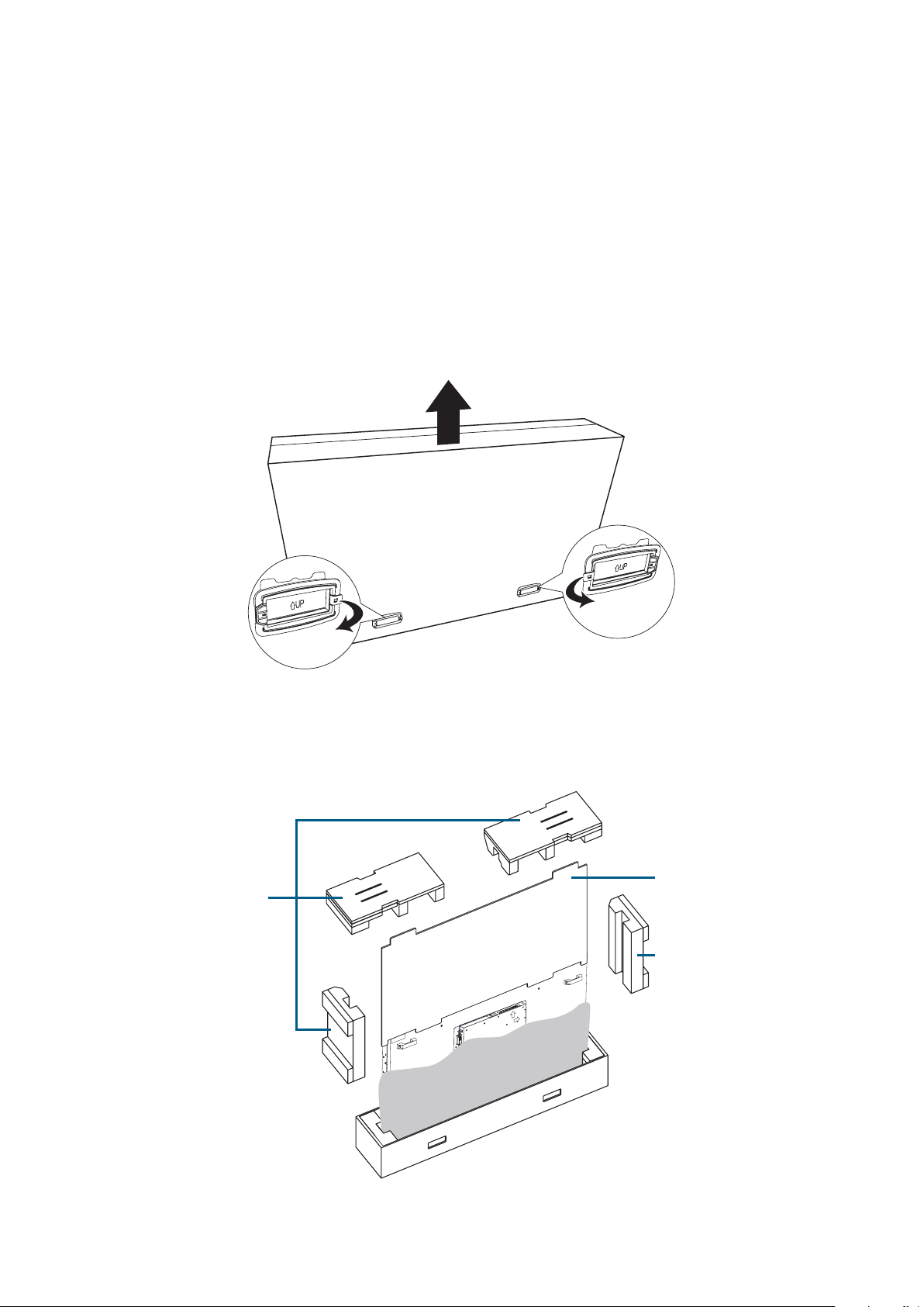
Unpacking
Before unpacking the display, prepare a flat and stable surface near a wall outlet. Set the product
box in an upright position.
1. Pull the hand-hold clip lock outward to the unlock position.
2. Remove the four hand-hold clips.
3. Remove the upper case from the top of the box.
4. Remove the four pieces of EPE foam packaging cushion.
5. Remove the protective board.
6. Carefully unwrap the plastic bag around the display.
Protective Board
EPE Foam
EPE Foam
4 | « What’s in the Box »
Page 5
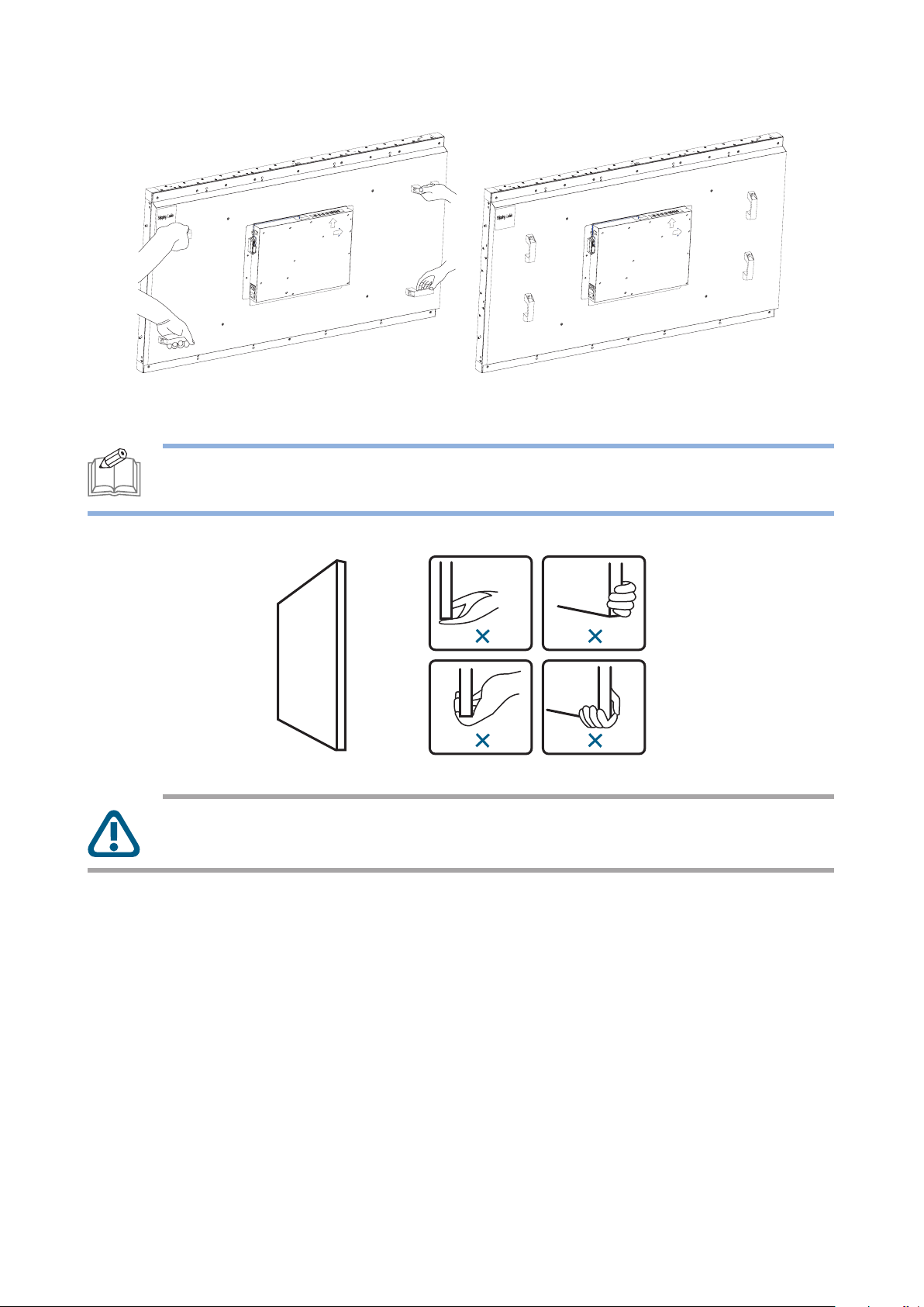
7. Grasp the carrying handles firmly and lift up to remove the display out of the box.
The orientation of the carrying handles may vary depending on model.
NOTE: Always hold the carrying handles securely with two people using both hands.
Do not lift the display from the bottom.
CAUTION: Avoid touching and applying the stress on the LCD panel or the frame
around the screen at all times.
« What’s in the Box » | 5
Page 6
Package Contents
Check your product box for the following items. If there are any missing accessories, contact the
local dealer where you purchased your product. The illustrations in this manual may differ from the
actual product and item.
• 55” LCD video-wall display
• AC power cord
• Infrared remote control
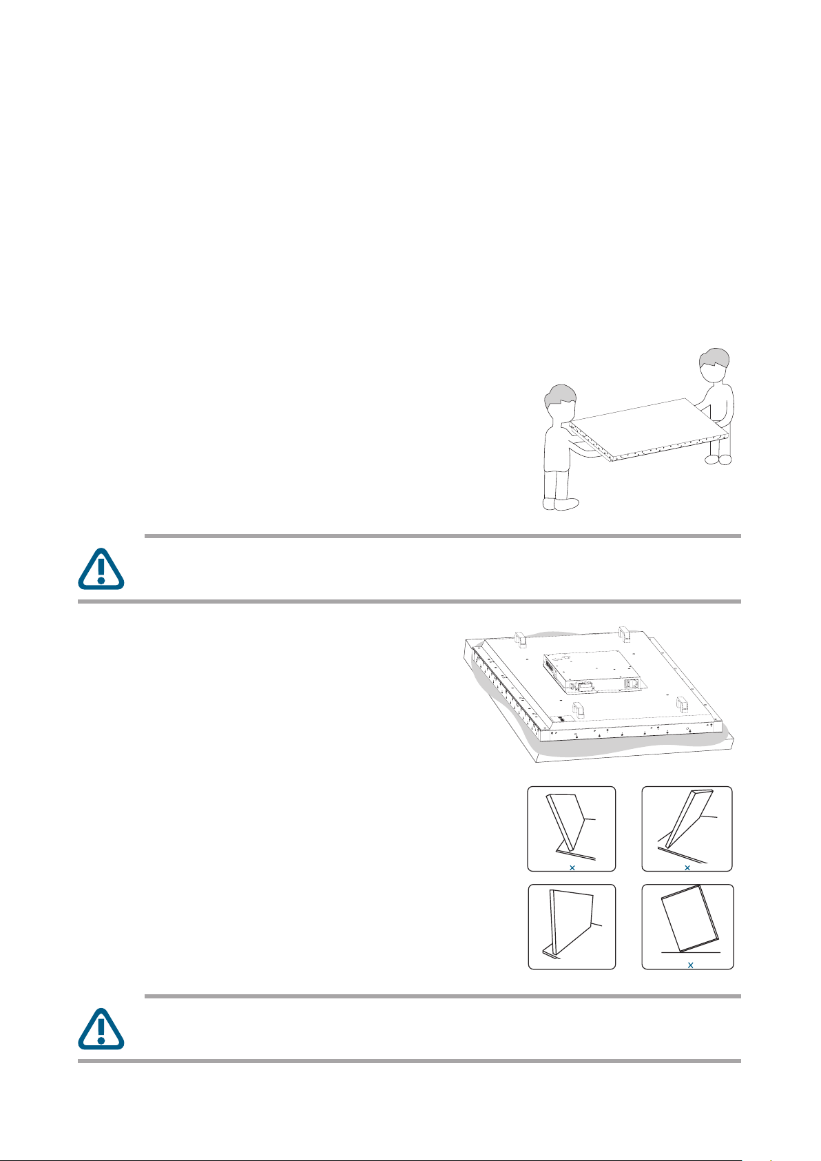
Moving and Carrying the Display
• When carrying the display, always hold
the carrying handles with two hands and
move around horizontally as shown in the
illustration provided.
CAUTION: NEVER carry the display alone and NEVER grip the display around the
bezel edges.
• When placing the display, place the screen
face down on a flat and stable surface
covered by a protective sheet and table
cushion.
• When placing the display, keep the display
upright, never tilt it towards the left or right
or balanced on a single corner of the frame.
CAUTION: Never press or place anything on the back cover. This may damage the
internal parts.
6 | « What’s in the Box »
Page 7
Mounting the Display
When mounting the display on a wall or an enclosed area, it is strongly recommends that you use
the wall-mount kit designed for your display with the installation of the wall mount performed by a
qualified service technician or licensed contractor.
NOTE: The wall-video displays should be installed on a flat surface. Make sure to leave
enough space around the display for proper air circulation and heat dissipation.
« What’s in the Box » | 7
Page 8
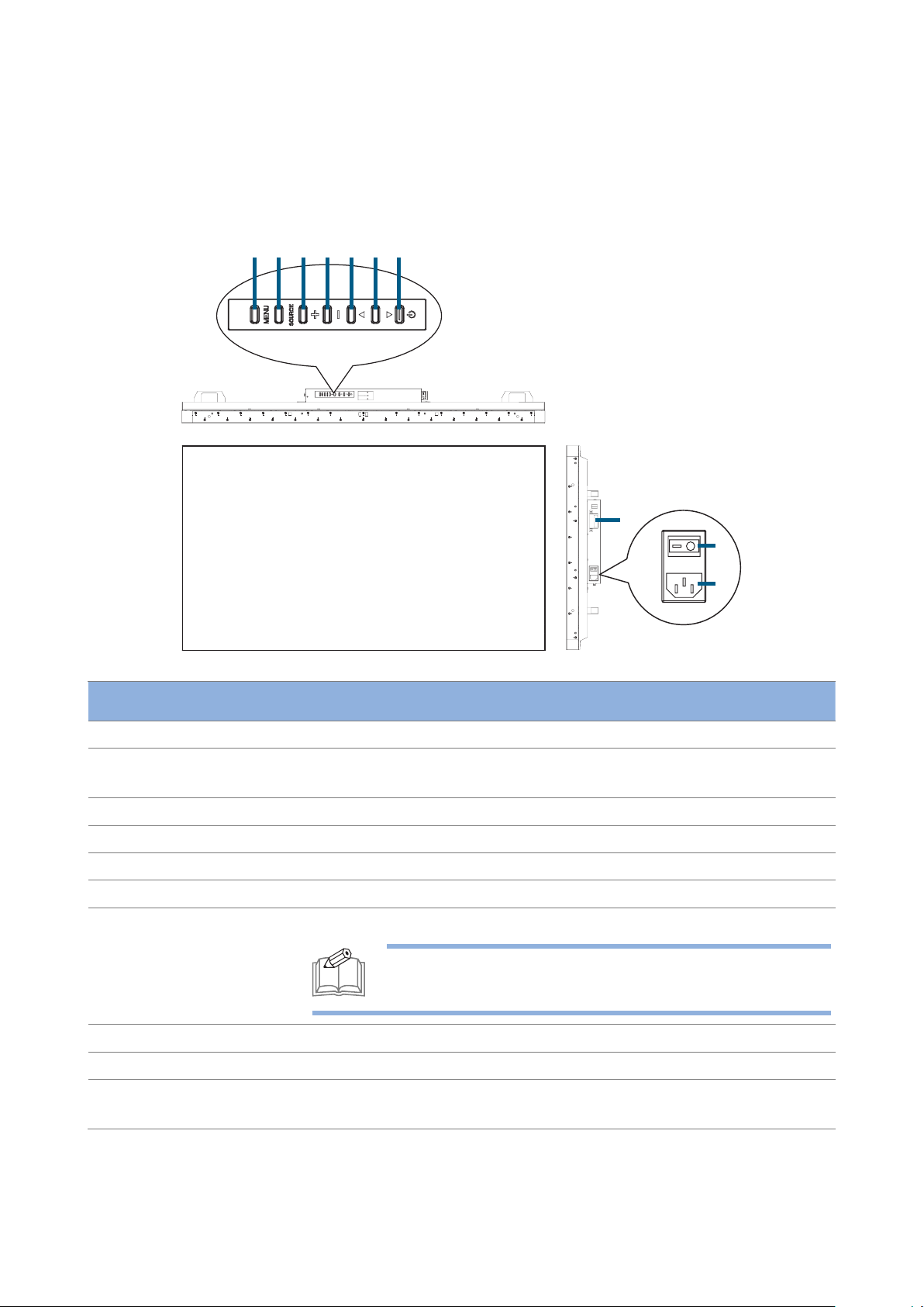
Features
1234567
Control Panel
8
9
10
Item Description
1 MENU Button Enters the On Screen Display (OSD) menu.
2 SOURCE Button Displays the OSD menu to switch the video input. You can select [AV],
[COMPONENT], [HDMI1], [HDMI2], [DVI-D], [VGA], and [USB].
3 PLUS (+) Button Increases volume.
4 MINUS (–) Button Decreases volume.
5 UP () Button Moves the selection up in the OSD menu.
6 DOWN () Button Moves the selection down in the OSD menu.
7 POWER Button Turns the power on/off.
NOTE: This button does not work if the main power
switch is off. In such cases, turn on the main power switch.
8 IR sensor Receives the signal from the remote control.
9 Main Power Switch Switches the main power on/off.
10 AC-In Connects with the supplied power cord. Class I Product requires an
earthed mains supply connection.
Connectors and Terminals
8 | « Features »
Page 9

7
10
11
654321
8
9
Connector Description
1 LINE OUT Outputs the signal that is supplied to the LINE IN connector (#2).
Connects with an external audio amplifier, etc.
Headphones and earphones are not supported.
2 LINE IN Connects with the AV output connector from external equipment
such as a computer, VCR, and DVD player.
3 VGA IN Connects with the analog video output of a computer.
4 USB Port Connects with a USB device to update the firmware.
5 HDMI2 Connects with devices supporting audio/video data using the HDMI
interface.
6 HDMI1 Connects with devices supporting audio/video data using the HDMI
interface.
7 LAN (RJ-45) Connects with an Ethernet cable for LAN access.
8 RS-232C OUT Connects with the RS-232C IN connector of other connected
P550HVF display.
9 RS-232C IN Connects with the RS-232C OUT connector of a computer or
other connected P550HVF display.
10 DVI-D OUT Outputs the signal that is supplied to the DVI-D IN connector (#11).
11 DVI-D IN Connects with the digital video output of a computer, etc.
« Features » | 9
Page 10

Remote Control
3
4
8
9
15
11
10
13
Button Description
1 POWER Switches the power on/off. When
the power indicator is not lit, no
controls will work.
2 SOUND Toggles the sound mode between
[STANDARD], [DYNAMIC], and
[CUSTOM].
3 PICTURE Toggles the picture mode
between [DYNAMIC],
[ADVERTISER], [CUSTOM], and
[STANDARD].
4 INFO Displays the current screen
resolution and refresh rate.
5 VOLUME Adjusts the display’s volume.
[+] increase [–] decrease
6
MUTE
Switches the mute function on/
off.
7
UP/DOWN/
LEFT/RIGHT
Moves the selection in the OSD
menu.
8 MENU Displays the OSD menu.
9 MEDIA CONTROL These contextual buttons provide
various media control functions
in specific menus. Each button’s
functions will be shown in the
OSD in corresponding colors.
1
2
5
6
7
12
14
10 INPUT Selects the video input source.
11 ASPECT Displays the current aspect ratio.
12 INPUT
Switches the video input source. Use the or buttons to
directly select [AV], [COMPONENT], [HDMI1], [HDMI2], [DVI-D],
[VGA], and [USB].
13 OK Accepts the settings made in the OSD menu.
14 BACK Returns to the previous OSD menu.
15 AUDIO/
VIDEO CONTROL
These buttons provide control functions when playing media files.
PAUSE STOP PLAY
PREV NEXT Fast Reverse Fast Forward
10 | « Features »
Page 11

Using the remote control
Make sure to point the remote control at the IR sensor on the display.
If the remote control is not working, replace the batteries with new ones and make sure that they
are correctly inserted: place two 1.5V AAA batteries matching the (+) and (–) signs to the (+) and (–)
indications of the battery compartment.
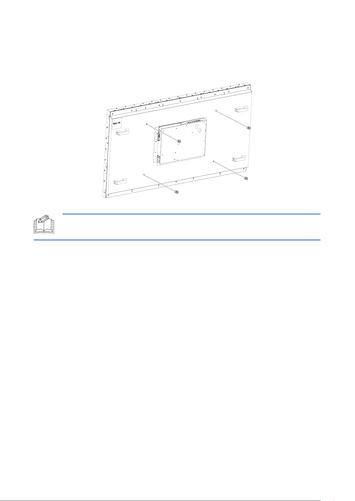
Setting up the IR sensor
Before using the infrared remote control, the IR sensor must be positioned correctly. The IR sensor
is the small black box located on the back side of left of the LCD display.
To set up the IR sensor:
1. Remove the two screws as indicated in the image below.
2. Unthread the cables from the cable clip.
3. As the IR sensor moves with the magnet, hold and place the IR sensor onto the back side of
the LCD display and slowly slide the IR sensor until it is in place.
Reverse this procedure to return the sensor to its original position.
It is strongly recommended that you place the IR sensor at the bottom-left corner or bottom-right
corner of the back side of the display. In the case of a daisy-chain connection, always place the IR
sensor at the outer bottom-corners, ensuring the IR sensors will receive the signal across a wide
angle.
« Features » | 11
Page 12

Operating range of the remote control
Point the infrared remote control toward the display’s remote control sensor when operating the
remote control. Ensure the remote control is aimed at the correct location where the IR sensor is
placed. Use the remote control within a distance of less than 10m/32.8ft from the IR sensor, and a
horizontal and vertical angle of less than 30 degrees.
30°30°
NOTE:
• Using the remote control beyond this distance, or with an object obstructing the
path of the signal, may cause a communication failure.
• The remote control may not function properly when the IR sensor on the display is
under direct sunlight or strong illumination.
12 | « Features »
Page 13

Getting Started
Setting up the LCD Display
Connecting the power cable
Before making any connections, make sure that the main power switch is off.
1. Plug the power cord into the display.
2. Fully insert the plug into the power outlet socket. Loose connections may cause noise. Do not
plug and unplug the power cord repeatedly in a short period of time.
NOTE:
• This display is equipped with a three-pronged grounded plug (a plug with a third
grounding pin). This plug will fit only into a grounded power outlet as a safety feature.
If your outlet is not suitable for the three-pronged plug, consult an electrician for a
solution. Do not bypass the safety purpose of the grounded plug
• The supplied power cord varies depending on the country where you purchased this
apparatus. For all cases, use a power cord that matches the AC voltage of the power
outlet and has been approved by and complies with the safety standard of your
country.
• When disconnecting the AC power cord, be absolutely sure to disconnect the plug
at the socket outlet first.
« Getting Started » | 13
Page 14

Tiling configuration
ü
This feature provides a single large-screen matrix (video-wall) using up to 25 displays (up to 5 set
horizontally and 5 set vertically). This function requires a daisy-chain connection. For more details,
see “Interconnecting the displays”.
CAUTION: Keep the displays horizontally or vertically straight when the individual
displays are tiled together.
The displays can be tiled in portrait or landscape orientation. Ensure that the display is oriented as
shown in the following illustrations.
NOTE: In portrait orientation, the lifetime of the backlight is shorter than in landscape
orientation.
14 | « Getting Started »
Page 15

Interconnecting the displays
[DVI]
[DVI OUT]
You can interconnect multiple displays to create a daisy-chain configuration for multi-screen
applications such as a video wall.
NOTE:
• The daisy-chain connection allows up to 25 LCD displays. However, the maximum
number of connectable LCD displays may be limited. It is recommended to check
the number of connectable LCD displays in your installation environment in advance.
• To protect the connected equipment, turn off the main power switch before making
connections.
1. Use the DVI cross cable/RS-232C cross cable/HDMI cable to connect the computer to this
display, and from display to display.
2. Press the [MENU] button to display the OSD menu and select [Multi Display Control] [Tiling]
to enable the tiling mode and select [Monitor ID] to set the display’s ID number.
For more details on setting the multi-display functions, check the on-screen menu provided by the
display.
Display 1
[DVI IN]
NOTE: The illustration shown here is for example purposes only. For different input
video content, use the proper connection cable to connect to the corresponding
connectors (for example, HDMI port, RS-232C port, or VGA port).
[DVI OUT]
[DVI OUT]
Display 4 Display 3
Display 2
[DVI IN]
[DVI IN][DVI IN]
« Getting Started » | 15
Page 16

Connecting External Equipment
Before making connections, make sure that the power of all the connected equipment is off.
Connecting with video devices
Analog connection
1. Connect a composite (A/V) cable to the VGA-IN connector and connect an audio cable to the
LINE IN connector.
2. Press the [INPUT] button to select the video input source (VGA or AV). Once selected, the
audio input setting automatically switches to [LINE IN].
Digital connection
1. Connect an HDMI (or DVI-D cable) to the HDMI1 or HDMI2 connector (or DVI-D IN
connector).
2. Press the [INPUT] button to select the video input source (HDMI1, HDMI2 or DVI-D). The
default audio input setting is a TMDS signal with HDMI/DVI cable. You can use external audio
by connecting an audio cable to the LINE IN connector. Once connected, press the [MENU]
button to display the OSD menu and select [Sound] [Audio Source] to set the audio input
source as [LINE IN].
16 | « Getting Started »
Page 17

Connecting a PC
Using the HDMI port
Using the DVI-D port
Using the VGA port
NOTE: Once connected, press the [INPUT] button to set the video input according to
the type of connection made.
« Getting Started » | 17
Page 18

Connecting to the Internet
You can connect this display and a computer in a network through a LAN hub by using a LAN
straight cable.
To connect to the Internet:
1. Turn off the main power switch of the computer and this display. If you make a connection
while the power is on, the devices may fail.
2. Use the LAN straight cables to connect the computer, the LAN hub, and the display.
NOTE: When you use a LAN cross cable, you can connect the display and the computer
one-to-one without using a LAN hub depend on the type of connection your computer
supports.
LAN remote control
The display supports two communication interfaces: LAN and RS-232C. By using the two
communication interfaces, you can control displays remotely:
• Use an RJ-45 connector for Ethernet networking as described above.
• Use an RS-232C cross cable (reversed).
For connection with a 25-pin serial port connector on the computer, an adapter (commercially
available) is required.
For direct connection using RS-232C, use the RxD, TxD, and GND transmission lines.
When you connect the display and the computer using a LAN hub and a LAN cable, and configure
the network settings using [Ethernet Setting] in the [Setup] menu of the OSD, you can control the
LCD display remotely (use the same commands as for RS-232C).
18 | « Getting Started »
Page 19

To set the remote control commands:
NOTE: Please contact your local agent for details of the control functions, including
network parameters and command sets.
1. Select [MENU] [Setup] [Control Setting] to enable the LAN connection as the
communication interface used for the serial communication function.
2. Setup the network parameters.
3. Set the IP address and the port number (4660) using the application program of your
computer to perform the socket communication.
4. Send the control command via TCP/IP socket communication.
5. Check the return command sent from the LCD display. When it is received successfully, the
setting is complete.
NOTE: If [LAN] is selected, [RS-232C] will not be activated, even if a cable is attached,
and vice versa
Connecting to a USB device
You can update the firmware on the LCD display via the USB port.
To update the firmware:
1. Download the latest firmware for the LCD display to a USB storage medium.
2. Insert USB storage medium into the USB port of the display.
3. Use the [INPUT] button on the remote control or the [SOURCE] button on the display’s
control panel to select USB as the input source.
4. Select [MENU] [Setup] [Software update (USB)] to update the firmware.
NOTE: Some USB hubs may not work. If a USB device is connected using a USB hub is
not detected, connect it to the USB port on the display directly.
« Getting Started » | 19
Page 20

How to Use the LCD Display
Turning On All the Devices
1. Turn on all the attached external devices, such as a computer or DVD player and make sure
that the cables are properly connected.
2. Make sure the IR sensor has been properly set up. For more details, see “Setting up the IR
sensor”.
3. Turn on the main power switch of the display.
4. Press the [POWER] button on the remote control or on the LCD display’s control panel to
turn on the LCD display.
CAUTION:
• DO NOT turn off the main power switch or disconnect the power cable within two
seconds of turning off the power of the display via the remote control, the control
panel of the display, or communication command. If the AC power is turned off
immediately after the power-off operation, all the OSD settings will be reset to the
factory defaults the next time the display is powered on.
• If you turn off the display by detaching the power cable, wait for at least 2 seconds
before re-attaching the power cable for normal operation.
20 | « How to Use the LCD Display »
Page 21

Using the LCD Display
When you turn the display on for the first time, you need to adjust the basic setting of the display
by entering the OSD menu.
Follow the OSD menu to customize the settings according to your preferences.
Selecting the video input
Press the [INPUT] button to select the desired video input source (VGA, HDMI1, HDMI2, AV,
YPbPr, DVI or USB). Alternatively, press the or buttons on the remote control to directly
switch the video input source.
Selecting the OSD language
Press the [MENU] button to display the OSD menu, and select [Initial Setting] [Menu Language]
to select the desired OSD language (English, French, German, Spanish, Italian, Swedish, Japanese, or
Simplified Chinese).
Selecting the picture mode
Press the [MENU] button to display the OSD menu, and select [Picture] [Picture Mode] to select
the picture mode suitable for the display. You can also adjust picture settings to obtain the desired
image quality.
Selecting the audio
Press the [MENU] button to display the OSD menu, and select [Sound] [Speaker] to select
whether the built-in speakers or external stereo speakers are to be used as the audio. Select
[Audio Source] to select which source to use for audio input from all available audio sources (LINE
IN, HDMI2, etc).
NOTE: An audio source must be connected to the display to be available.
Setting the schedule
Press the [MENU] button to display the OSD menu, and select [Setup] [Scheduler] to program
the power-on/off time and the preferred audio-video input source.
NOTE:
• Make sure the Enable Schedule option is selected before leaving the schedule setting
screen.
• Make sure to check the current date and time by selecting [MENU]
[Initial Setting] [Clock] before making the schedule settings.
• When the AC power supply turns off or the circuit breaker trips due to power
failure or other causes, the schedule programs will be kept and executed when the
AC power supply returns. However, system time will not be correct if the AC power
is off for more than 168 hours.
« How to Use the LCD Display » | 21
Page 22

Power management function
This display supports three power-off methods to reduce power consumption:
Sleep Timer
You can set the timer to automatically shut off the display after a pre-configured period of time by
selecting [MENU] [Setup] [Sleep Timer].
NOTE: The sleep timer function is a run-once function. The function will only be
executed once and will be deactivated the next time the display is powered on.
Power Saving Timer
You can set the power saving timer to turn off the display when the current source has no signal by
selecting [MENU] [Setup] [Power Save].
NOTE: The value by default is 300 seconds.
NOTE: If the display switches to standby mode as a result of the Power Saving Timer for
a VGA or HDMI source (but not DVI-D), the display will power on automatically if the
signal from the current source returns. Not all video devices support the auto power on
function when connected to the display.
Schedule
You can program up to seven different scheduled time intervals to determine power on times and
power off times. You can program:
• The time for the display to turn on and turn off.
• The days in a week for the display to activate.
• Which input source the display will use for each scheduled activation period.
For more details on the schedule function, see “Setting the schedule”.
22 | « How to Use the LCD Display »
Page 23

On Screen Display (OSD) Menu
This LCD display is equipped with an OSD (On Screen Display) menu for easy adjustment of the
display’s settings.
Navigating the OSD menu
Using the remote control
1. Press the [MENU] button to display the OSD menu.
2. Press the [UP] or [DOWN] button to choose the sub-menu items
and press the [OK] button.
3. In the sub-menu, press the [LEFT] or [RIGHT] button to select
the settings you want to adjust. If there is a sub-list under the
sub-menu, press the [OK] button again to enter the sub-list.
4. Press the [EXIT] button to return to the previous menu, or press
the [MENU] button to exit the OSD menu.
Using the control panel
1. Press the [MENU] button to display the OSD menu.
2. Press the [] or [] button to choose the sub-menu items and
press the [SOURCE] button to enter the sub-menu.
3. In the sub-menu, press the [+] or [–] button to select the settings
you want to adjust. If there is a sub-list under the sub-menu, press
the [SOURCE] button again to enter the sub-list.
4. Press the [MENU] button to return to the previous menu, or press
the [MENU] button several times to exit the OSD menu.
« On Screen Display (OSD) Menu » | 23
Page 24

OSD Menu Overview
The tables below list the initial OSD functions in the main menu screen. For more detailed options,
check the on-screen menu provided by the display.
• Picture
Picture mode
Backlight
Color Temperature
Gamma
Noise Reduction
Adaptive Contrast
Over Scan
Aspect Ratio
Color Range
VGA setting
Reset Picture Setting
• Picture Style: Standard/Dynamic/Advertiser/Custom
• Contrast: 0-100
• Brightness: 0-10
• Sharpness: 0-10
• Tint
• Color
0-100
• Color Temperature: 6500K/9300K/11500K/4900K/Custom
• Red Gain: 0-2047
• Green Gain: 0-2047
• Blue Gain: 0-2047
2.2/2.4/Native
Off/Weak/Middle/Strong
On/Off
On/Off/Auto
4:3/16:9/Zoom/Cinema/Dot by Dot (Depends on the Source
ID setting)
0~255/16~235/Automatic
• H Position: 0-100
• V position: 0-68
• Clock: 0-100
• Phase: 0-100
• Auto Adjustment: Enable/Disable
• Auto
24 | « On Screen Display (OSD) Menu »
Page 25

• Sound
Sound Mode
• Sound Style: Standard/Dynamic/Custom
• Treble
• Bass
• Balance
Surround Sound
Speaker
Audio Only
Audio Source
Reset Audio Setting
• Setup
Scheduler
Signal Check Priority
Control Setting
Standby Mode
Ethernet Setting
Sleep Timer
Power Save
Software Update (USB)
Restore Default
• Initial Setting
OSD Rotation
Menu Language
Time Format
Clock
Light Sensor
Remote Operation
Keypad Operation
Anti-Image Retention
On/Off
Internal/External
On/Off
Line In/HDMI 1
Set signal priority 1 to 5
Off/RS232/LAN
ECO/Normal
Landscape/Portrait
English/French/German/Spanish/Italian/Swedish/Japanese/
CN_Chinese
12 Hour/24 Hour
Year/Month/Day/Hour/Minute
On/Off
Enable/Disable
Enable/Disable
Off/picture shift /White pixel
• Multi Display Control
Tiling
Tiling Mode
Screen Position
Monitor ID
Frame Compensation
Power ON Delay
• System Information
Model Name
SW Version
LAN Version
IP Address
Enable/Disable
Horizontal/Vertical
Horizontal/Vertical
01-25
On/Off
Off/0.5-30 seconds/0.5 sec. Steps/Auto
« On Screen Display (OSD) Menu » | 25
Page 26

Technical Specifications
Item DW460 DW550
LCD Panel
LCD Size (inch) 46 54.6
Resolution (pixel) 1920 (H) × 1080 (V)
Brightness (cd/m2) 700
Contrast Ratio (typ.) 4000:1
Response Time (ms) 6.5 8
Viewing Angle (degree) 178 (H) / 178 (V)
LED Life (hr) 50,000
Surface Treatment Anti-Glare 3H, Haze 11% Anti-Glare 3H, Haze 44%
Display Color Depth 10 bit (1073.7M) 8 bit (16.7M Colors)
Power Source
Power supply (V) AC 100~240 ( 50/60Hz)
Power consumption (Watt) < 155W < 195W
Standby Power (Watt) < 1W
Display
Horizontal Frequency (kHz) 60-73 67.5
Vertical Frequency (Hz) 47-63 60
OSD Control IR remote control, RS232, RJ45 controller
Wall Mounting (mm) 600 x 400
Input/Output Terminals
Input Connector HDMI x 2, DVI x 1, VGA x 1, Audio x 1, RS232 x 1,
RJ45 x 1, USB x 1 (supports the firmware update only),
IR remote control x 1
Output Connector DVI x 1, Audio x 1, RS232 x 1
Dimensions
W × H × D (mm) 1023.7 × 578.3 × 110.2 1211.8 × 682.6 × 114.2
Weight (kg) 23 28
26 | « Technical Specifications »
 Loading...