

Page 1
Page 2

Contents
Important Safety Instructions ................................................................................................2
Installation, Care, and Service ...............................................................................................3
Chapter 1: Introduction ..........................................................................................................6
Safety Icons.............................................................................................................................................. 6
Features of your new LCD Display .......................................................................................................... 7
Package Contents ................................................................................................................................... 8
Parts Name and Functions....................................................................................................................... 9
Connectors and Terminals...................................................................................................................... 11
Infrared Remote Control ......................................................................................................................... 13
How to Use the Infrared Remote Control................................................................................................ 14
Chapter 2: Preparation for use............................................................................................. 17
Preparation for installation ...................................................................................................................... 17
Determine the installation location .......................................................................................................... 17
Ventilation requirements for enclosure mounting ................................................................................... 17
Using the wall mount or ceiling mount or handles .................................................................................. 19
Installation in portrait or landscape orientation ....................................................................................... 22
Avoiding Image Retention ...................................................................................................................... 23
Connection procedure ............................................................................................................................ 24
Connecting with an analog video source ................................................................................................ 25
Connecting with a digital video source ................................................................................................... 26
Digital connection: .................................................................................................................................. 26
Connecting LAN....................................................................................................................................... 28
Display connection using LAN................................................................................................................. 28
Connecting the power cord to the display............................................................................................... 28
Connecting the power source................................................................................................................. 28
Chapter 3: How to use the LCD Display Monitor .............................................................. 30
Turning on all the connected devices...................................................................................................... 30
Power Management Function.................................................................................................................. 33
Selecting the video input ......................................................................................................................... 34
Select using the SOURCE button on the infrared remote control ........................................................... 34
Select using the SOURCE button on the LCD display ............................................................................ 34
Controlling the external devices .............................................................................................................. 34
Selecting the OSD language.................................................................................................................... 35
Initial Setting ........................................................................................................................................... 36
Page 3

Selecting the picture mode ..................................................................................................................... 37
Picture adjustment................................................................................................................................... 38
Audio settings.......................................................................................................................................... 39
Treble, bass, and balance adjustment .................................................................................................... 40
Schedule setting ..................................................................................................................................... 41
How to set up a schedule......................................................................................................................... 42
Viewing media from USB storage ........................................................................................................... 44
Setting up a playlist.................................................................................................................................. 46
Playing background music ...................................................................................................................... 48
Slideshow settings .................................................................................................................................. 48
Playing a playlist ..................................................................................................................................... 49
Remote control........................................................................................................................................ 52
LAN remote control ................................................................................................................................. 55
Configuration and basic operation of the OSD screen ............................................................................ 56
Basic operation of OSD screen............................................................................................................... 57
Picture Menu Screen .............................................................................................................................. 59
Aspect Ratio Menu Settings ................................................................................................................... 60
Sound Menu Screen.............................................................................................................................. 61
Setup Menu Screen............................................................................................................................... 62
Initial Setting Menu Screen .................................................................................................................... 63
Multi Display Control Menu Screen ........................................................................................................ 64
System Information Menu Screen.......................................................................................................... 66
Appendix A.............................................................................................................................67
Specifications .......................................................................................................................................... 67
LCD Module ............................................................................................................................................ 67
Viewable Size (H x V) ............................................................................................................................. 68
Power Management ................................................................................................................................ 68
Power source .......................................................................................................................................... 68
Power consumption .................................................................................................................................68
Input/Output Signal ................................................................................................................................. 68
AV Input/Output .......................................................................................................................................69
Audio Input/Output................................................................................................................................... 69
Dimensions ............................................................................................................................................. 69
Mass (weight) ......................................................................................................................................... 70
Page 4
2
Dear Customer,
Thank you for purchasing this LCD Display monitor. This
manual will help you use the many exciting features of
your new LCD Display monitor. Before operating your
LCD Display monitor, please read this manual
completely, and keep it nearby for future reference.
WARNING
Important Safety Instructions
1) Read these instructions.
2) Keep these instructions.
3) Heed all warnings.
4) Follow all instructions.
5) Do not use this apparatus near water.
6) Clean only with dry cloth.
7) Do not block any ventilation openings. Install in
accordance with the manufacturer’s instructions.
8) Do not install near any heat sources such as radiators, heat registers, stoves, or other apparatus (including amplifiers) that produce heat.
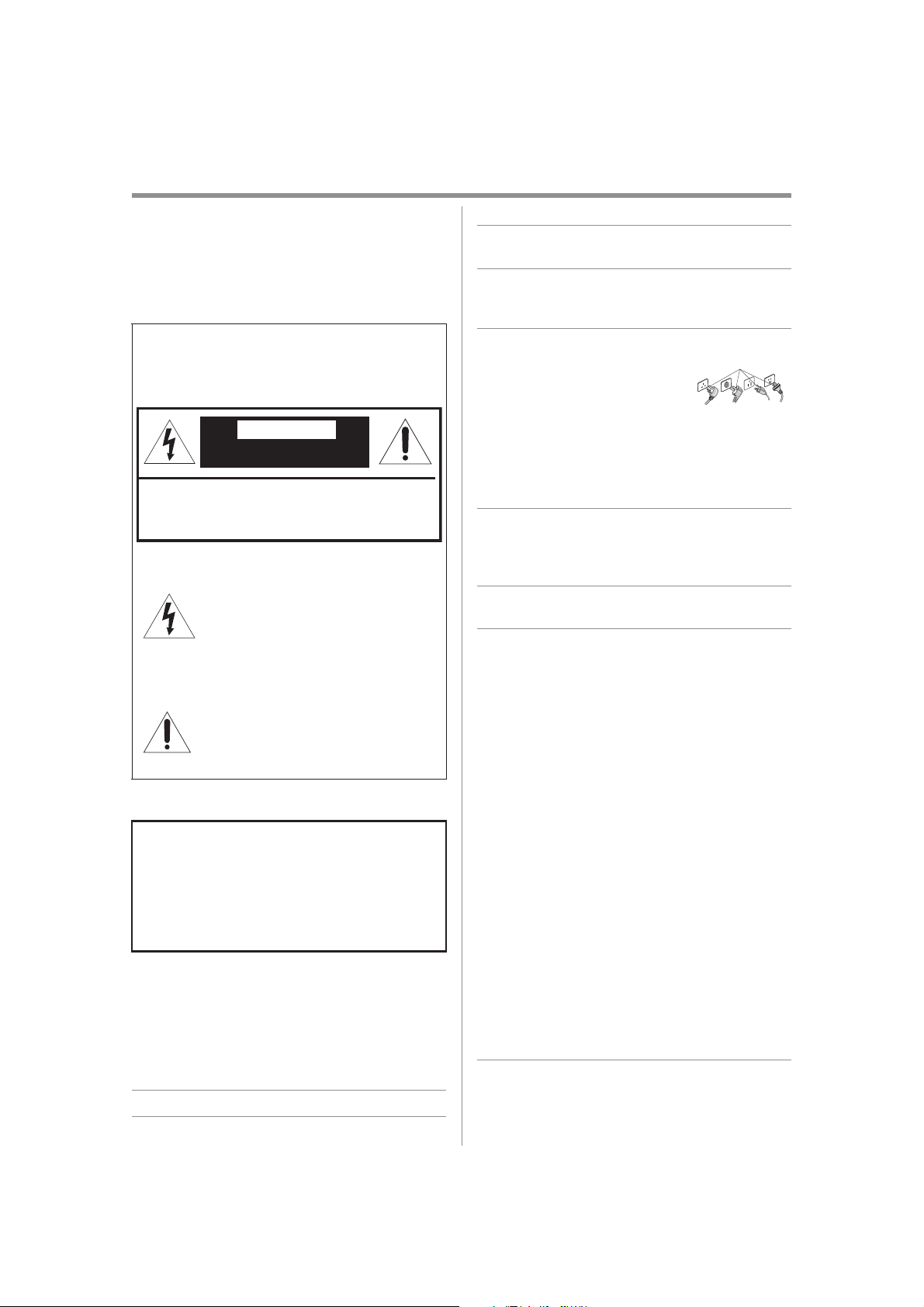
9) Do not defeat the safety purpose of
the polarized or grounding type
plug.
A polarized plug has two blades with
one wider than the other. A grounding type plug has two blades and a third grounding
prong. The wide blade or the third prong are provided
for your safety. If the provided plug does not fit into
your outlet, consult an electrician for replacement of
the obsolete outlet.
10) Protect the power cord from being walked on or
pinched, particularly at plugs, convenience
receptacles, and the point where they exit from the
apparatus.
11) Only use attachments/accessories specified by the
manufacturer.
12) Refer all servicing to qualified service personnel.
Servicing is required when the apparatus has been
damaged in any way, such as power-supply cord or
plug is damaged, liquid has been spilled or objects
have fallen into the apparatus, the apparatus has
been exposed to rain or moisture, does not operate
normally, or has been dropped.
Additional Safety Precautions
13) CAUTION: If the monitor is dropped and the cabinet
or enclosure surface has been damaged or the
monitor does not operate normally, take the following
precautions:
• ALWAYS turn off the monitor and unplug the power
cord to avoid possible electric shock or fire.
• NEVER allow your body to come in contact with any
broken glass or liquid from the damaged monitor
The LCD panel inside the monitor contains glass
and a toxic liquid. If the liquid comes in contact with
your mouth or eyes, or your skin is cut by broken
glass, rinse the affected area thoroughly with water
and consult your doctor.
• ALWAYS contact a service technician to inspect the
monitor any time it has been damaged or dropped.
Safety Precautions
WARNING: TO REDUCE THE RISK OF FIRE OR
ELECTRIC SHOCK, DO NOT EXPOSE THIS APPLIANCE
TO RAIN OR MOISTURE.
The lightning flash with arrowhead
symbol, within an equilateral triangle, is
intended to alert the user to the presence
of uninsulated “dangerous voltage” within
the product’s enclosure that may be of
sufficient magnitude to constitute a risk of
electric shock to persons.
The exclamation point within an equilateral
triangle is intended to alert the user to the
presence of important operating and
maintenance (servicing) instructions in the
literature accompanying the appliance.
WARNING: If you decide to wall mount this display,
always use a mounting bracket that has been Listed by
an independent laboratory (such as UL, CSA, ETL) and
is appropriate for the size and weight of this display.
The use of inappropriate or non-Listed mounting
brackets could result in serious bodily injury and/or
property damage
CAUTION:
RISK OF ELECTRIC SHOCK
DO NOT OPEN
CAUTION: TO PREVENT ELECTRICK SHOCK.
DO NOT REMOVE THE ENCLOSURE.
NO USER-SERVICIBLE PARTS INSIDE.
Grounding
UTC/cppl!!Qbhf!3!!Uvftebz-!Nbz!35-!3127!!6;66!QN
Page 5
DANGER: RISK OF SERIOUS PERSONAL
INJURY, DEATH, OR EQUIPMENT
DAMAGE!
UTC/cppl!!Qbhf!4!!Uvftebz-!Nbz!35-!3127!!6;66!QN
3
14) CAUTION:
• To reduce the risk of electric shock, do not use the
polarized plug with an extension cord, receptacle,
or other outlet unless the blades can be inserted
completely to prevent blade exposure.
• To prevent electric shock, match wide blade of plug
to wide slot; fully insert.
15) WARNING:
Do not let children swallow the product or play with
the plastic bag. Keep the product and the plastic bag
out of the reach of children.
16) CAUTION:
Do not let water or other liquids come into contact
with the product, as it may result in damage.
17) WARNING:
• To prevent the spread of fire, keep candles or other
open flames away from this product at all times.
• Keep the product away from direct sunlight, fire or a
heat source such as a heater. This may reduce the
product lifetime or result in fire.
Installation, Care, and Service
Installation
Follow these recommendations and precautions and
heed all warnings when installing your LCD Display
monitor:
18) When operating the LCD display with its AC 220240V power supply in Europe, use the power supply
provided with this display. If a power cord is not
supplied with this display, please contact your
supplier. This equipment requires an Earthed mains
supply connection.
19) In the UK, use a BS-approved power cord with
molded plug and black (10A) fuse installed.
20) When operating the LCD display with a 120V, 60Hz
AC power supply in the United States or Canada, use
the power cord provided with the display. If a power
cord is not supplied with the display, please contact
your supplier.
21) For all other cases, use a power cord that matches
the AC voltage of the power outlet and has been
approved by and complies with the safety standards
of your particular country.
22) Avoid displaying fixed patterns for long periods of
time, to avoid image persistence (after image
effects).
23) WARNING: NEVER expose batteries to
excessive heat such as sunshine, fire or
the like.
24) ALWAYS plug the product into an outlet that is
located in such a manner that it can be easily
unplugged in case the product requires service.
25) NEVER route the product’s power cord inside a wall
or similar enclosed area.
26) Never modify this equipment. Changes or
modifications may void: a) the warranty, and b) the
user’s authority to operate this equipment under the
rules of the Federal Communications Commission.
27)
Never place the monitor on an unstable
cart, stand, or table. The LCD Display may
fall, causing serious personal injury, death,
or serious damage to the monitor.
28) When selecting a location for the display,
• NEVER allow any part of the display to hang over
the edge of supporting furniture.
• NEVER place the display on tall furniture (for
example, entertainment centers or bookcases)
without anchoring both the furniture and the display
to a suitable support.
• NEVER allow children to climb on the monitor.
29) To avoid damage to this product, never place or store
the monitor in direct sunlight; hot, humid areas; or
areas subject to excessive dust or vibration.
30) The product should not be exposed to dripping or
splashing. Objects filled with liquids should not be
placed on the apparatus.
31) Never block or cover the slots or openings in the
monitor cabinet back, bottom, and sides. Never place
the monitor:
• On a bed, sofa, rug, or similar surface;
• Too close to drapes, curtains, or walls; or
• In a confined space such as a bookcase, built-in
cabinet, or any other place with poor ventilation.
32) Always leave a space of at least 10cm - 4 (four)
inches around the monitor.The slots and openings
are provided to protect the monitor from overheating
and to help maintain reliable operation of the
monitor.
Page 6
WARNING:
RISK OF ELECTRIC SHOCK
WARNING:
RISK OF ELECTRIC SHOCK
UTC/cppl!!Qbhf!5!!Uvftebz-!Nbz!35-!3127!!6;66!QN
4
33) Never allow anything to rest on or roll over the power
cord, and never place the monitor where the power
cord is subject to wear or abuse.
34) Never overload wall outlets and extension cords.
Ergonomics
For maximum ergonomic benefit, we recommend the
following:
35) For optimum performance, allow 20 minutes for
warm-up.
36) Rest your eyes periodically by focusing on an object
at least 5 feet away. Blink often.
37) Use the preset Size and Position controls with
standard signals.
38) Use the preset Color Setting.
39) Use non-interlaced signals.
40) Do not use primary color blue on a dark background,
as it is difficult to see and may produce eye fatigue
due to insufficient contrast.
41) Adjust the display’s brightness, contrast, and
sharpness controls to enhance readability.
42) Position the display at a 90° angle to windows and
other light sources to minimize glare and reflections.
Care
For better performance and safer operation of your LCD
Display monitor, follow these recommendations and
precautions:
43) Always unplug the monitor before cleaning. Gently
wipe the display panel surface (the monitor screen)
using a dry, soft cloth (cotton, flannel, etc.). A hard
cloth may damage the surface of the panel. Avoid
contact with alcohol, thinner, benzene, acidic or
alkaline solvent cleaners, abrasive cleaners, or
chemical cloths, which may damage the surface.
Never spray volatile compounds such as insecticide
on the cabinet. Such products may damage or
discolor the cabinet.
44) Never hit, press, or place anything on the back cover.
These actions will damage internal parts.
45)
47) Always unplug the monitor to completely disconnect
from mains power. When the monitor is turned off
using the on/off switch, it is not completely
disconnected from power and a minute amount of
current is still consumed.
48) During normal use, the monitor may make occasional
snapping or popping sounds. This is normal,
especially when the unit is being turned on or off. If
these sounds become frequent or continuous, unplug
the power cord and contact a Authorized Service
Provider.
49) Handle with care when transporting. Save packaging
for transporting. Please clean the ventilation slots on
the back of the cabinet to remove dirt and dust at
least once a year to maintain reliable operation of the
monitor.
50) If using the cooling fan continuously, it’s
recommended to clean the ventilation slots at least
once a month.
51) When installing the remote control batteries;
• Align the batteries according to the (+) and (-)
indications inside the case.
• Align the (-) indication of the batteries first inside
the case.
Service
52)
Never attempt to service the monitor yourself.
Opening and removing the covers may expose you to
dangerous voltage or other hazards. Failure to follow
this WARNING may result in death or serious injury.
Refer all servicing not specified in this manual to a
Authorized Service Provider.
53) If you have the monitor serviced:
• Ask the service technician to use only replacement
parts specified by the manufacturer.
• Upon completion of service, ask the service
technician to perform routine safety checks to
determine that the monitor is in safe operating
condition.
Never spill liquids or push objects of any kind into the
monitor cabinet slots.
46) During a lightning storm, do not touch the
connecting cables or product.
Page 7
6
Chapter 1
Introduction
Safety Icons
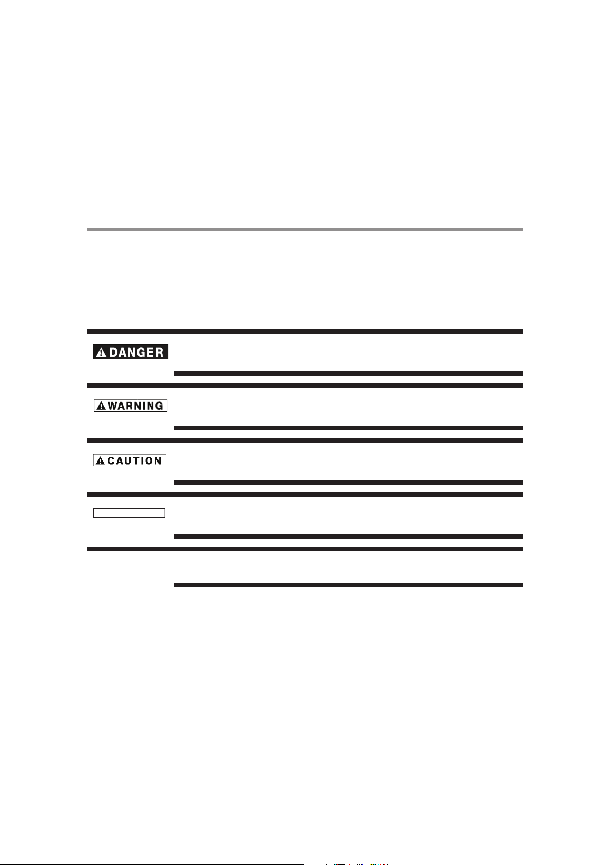
This manual contains safety instructions that must be observed to avoid potential hazards that could result in personal
injuries, damage to your equipment, or loss of data. These safety cautions have been classified according to the
seriousness of the risk, and icons highlight these instructions as follows:
Indicates an imminently hazardous situation which, if not avoided, will result in death or
serious injury.
Indicates a potentially hazardous situation which, if not avoided, could result in death or
serious injury.
Indicates a potentially hazardous situation which, if not avoided, may result in minor or moderate injury.
Indicates a potentially hazardous situation which, if not avoided, may result in property damage.
Provides important information.
C A U T I O N
N O T E
UTC/cppl!!Qbhf!7!!Uvftebz-!Nbz!35-!3127!!6;66!QN
Page 8

UTC/cppl!!Qbhf!8!!Uvftebz-!Nbz!35-!3127!!6;66!QN
Chapter 1
Introduction
Features of your new LCD Display
True Commercial 16/7 Operation Digital Display
43”, 50”, 55”, and 65”— These robust displays are specifically designed for long hours of trouble-free operation
in a commercial environment, as well as many other commercial features.
Industry LED backlight
LED backlight panel — Commercial grade panel with a LED backlight. With the LED backlight, the display has
achieved low power consumption and eliminated mercury. The slim display design allows installation in various
environments than the conventional displays. See page 30.
High-quality LCD panel providing a wide variety of content and messages clearly
Full HD panel — The LCD display panel reproduce images from video and computer signals with precision and
clarity, delivering full 1920 x 1080 high- definition resolution.
Brightness
450 cd/m
customer attention in a variety of lighting environments.
2
43”, 50”, 55”, 65” — Creates more compelling, dynamic images to better attract and maintain
7
Enhanced Display Functionality for Various Applications
Daisy Chain Connection — By connecting the DVI-D OUT connectors and the DVI-D IN connectors using DVI-
D cables (commercially available), you can transmit video signals to up to 9 displays (when using 2-meter cables).
This is useful when supplying a video signal to multiple displays.
LAN Control — You can control multiple displays by sending control commands from a computer via a LAN
network. See pages 28.
Others
Built-in Speakers — This display offers built-in stereo speakers to deliver audio messages. External stereo
speakers can also be used. The user can switch between external or built-in speakers from the menu.
Remote Control — An infrared remote control is supplied to control the various functions of this display,
including power on/off, input select, and menu access. See page 13-14.
USB Media Player — Display and schedule content without an external media player. Built-in USB Media Player
CODECs include:
• Video: MPG, MPEG, AVI, MKV, MOV, MP4, TS, M2TS, H.264 (up to level 4.0)
• Music: MP3, WMA, AAC
• Photo: JPG, BMP, PNG (BMPs and JPGs with a resolution larger than 1024x768 may take additional time to
display)
Page 9
UTC/cppl!!Qbhf!9!!Uvftebz-!Nbz!35-!3127!!6;66!QN
Chapter 1
8
Introduction
Package Contents
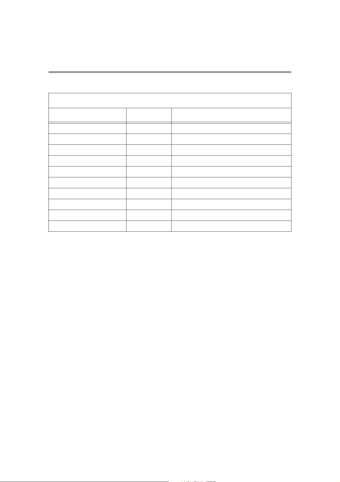
Contents
Item Unit Remark
LCD display 1
Infrared remote control 1
Batteries 2 AAA size
AC power cable 1 1.8m
3.5mm jack 1 Composite/component conversion cable
Logo cover sheet 1
User manual 1
Warranty Sheet 1 Except for EU models
QSG (Quick Setup Guide) 1 For EU models only
Cable Clamps 5
The supplied power cord varies depending on destination. For the use in the other regions, use a power cord that
matches the AC voltage of the power outlet and has been approved by and complies with the safety standard of those
regions or countries.
Page 10
7
1
2
3
4
5
6
Control buttons
UTC/cppl!!Qbhf!:!!Uvftebz-!Nbz!35-!3127!!6;66!QN
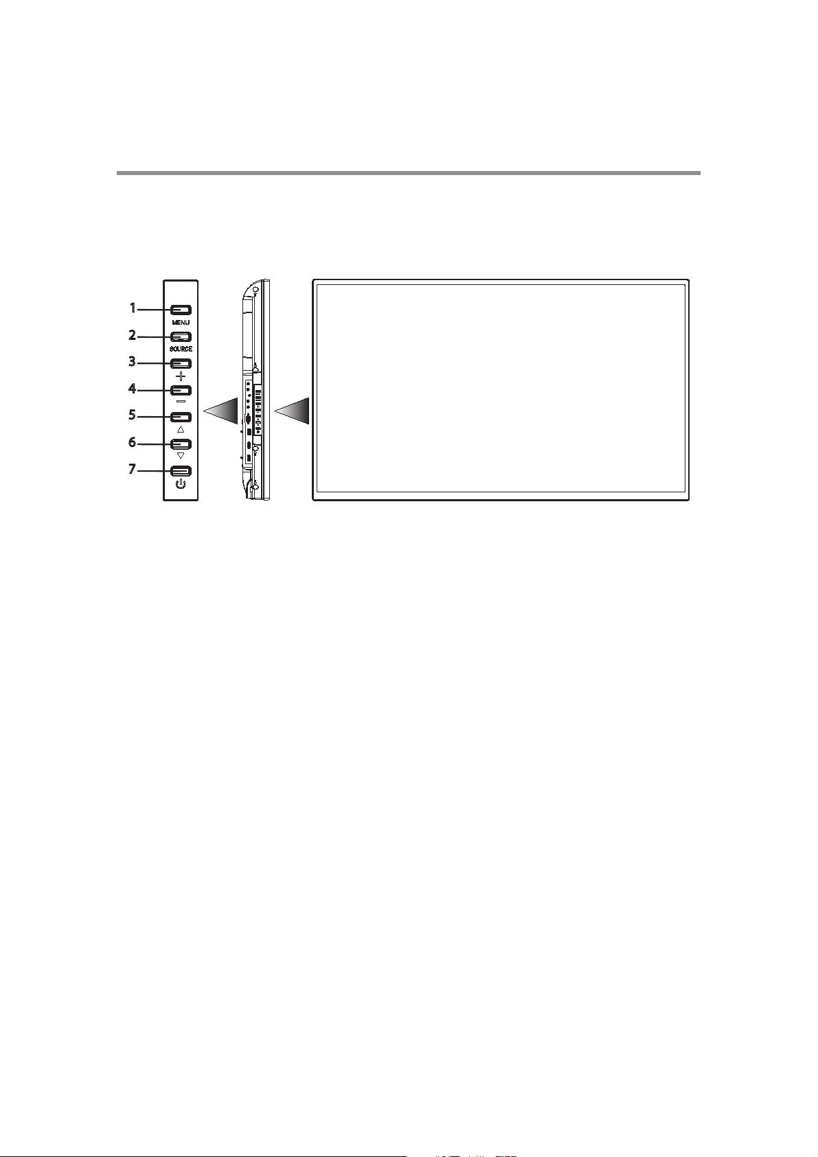
Parts Name and Functions
Buttons and Indicator
Left side Front
1 Menu button—Enters the On Screen Display (OSD) menu.
2 Source button—Displays the OSD menu to switch the video input. You can select [AV], [COMPONENT],
[HDMI1], [HDMI2], [DVI-D], [VGA], and [USB].
3 PLUS (+) button—Increases volume.
4 MINUS (-) button—Decreases volume.
Chapter 1
Introduction
9
5 UP ( ) button—Moves the highlighted area up in the OSD menu.
6 DOWN (!) button—Moves the highlighted area down in the OSD menu.
7 POWER button—Switches the power on/off. This button does not work when the power indicator is off. In such
cases, turn on the main power switch. (See page 10).
Page 11
Chapter 1
2
1
1
3
3
3
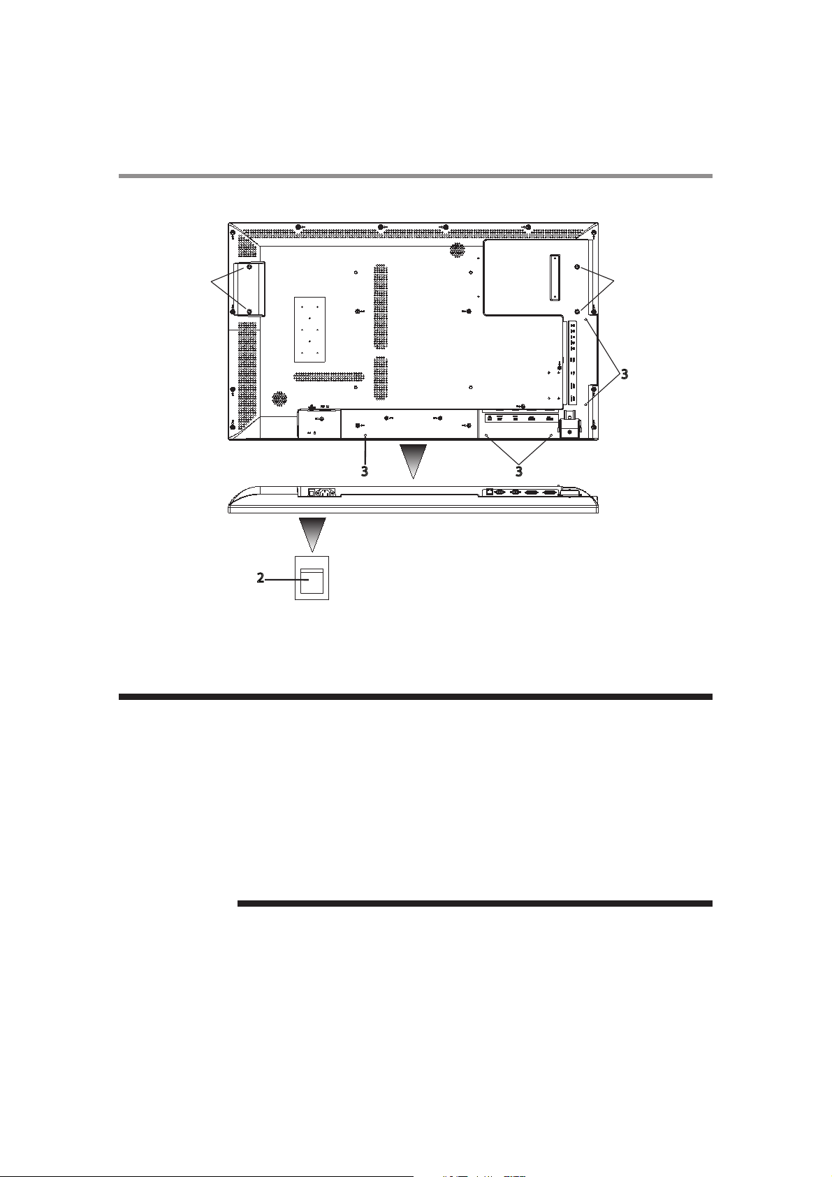
Back
Underside
N O T E
UTC/cppl!!Qbhf!21!!Uvftebz-!Nbz!35-!3127!!6;66!QN
10
Introduction
1 Handle screw holes —Used to mount handles (optional), for carrying the LCD display.
2 Main Power Switch —Switches the main power on/off and is used as the disconnect device.
3 Cable clamp holes — Used to clamp cables to the system.
Within 2 seconds after turning off the power by the POWER button on the infrared remote control or the display or by a communication command, don’t turn off the main power switch,
don’t disconnect the power cord, and don’t turn off the breaker. If the AC power is turned off
immediately after the power-off operation, all the OSD settings including the language selection may be reset to the factory defaults at the next power-on. If the OSD settings are reset to
the factory defaults as described above, reconfigure the OSD settings using the following
procedure.
• Turn off the power of the display using the infrared remote control or another method.
• Wait for at least 2 seconds.
• Turn on the power of the display using the infrared remote control or another method.
• Check and reconfigure the OSD settings.
Page 12
16
9
10
12
13
14
15
17
1
2 3 4
5
6
7
8
11
Underside
UTC/cppl!!Qbhf!22!!Uvftebz-!Nbz!35-!3127!!6;66!QN
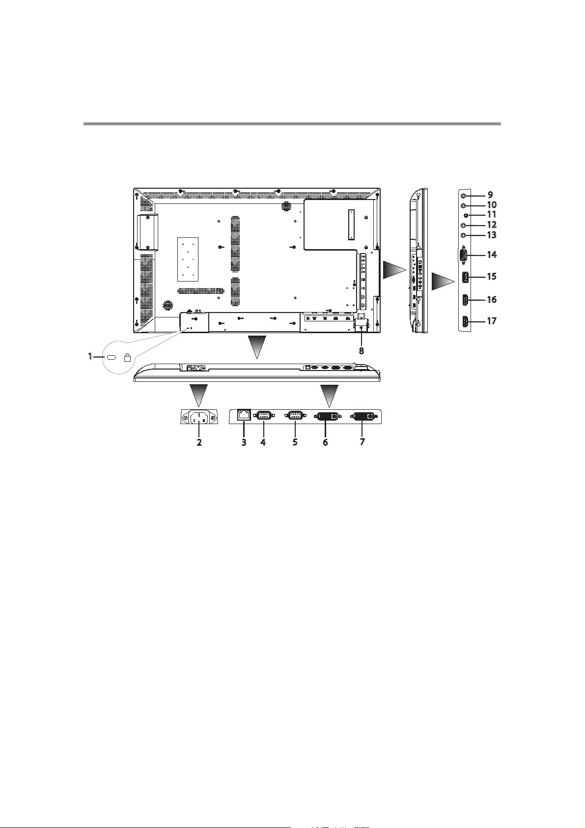
Connectors and Terminals
For details about using cable types and connections, see pages 24-26.
Back
Chapter 1
Introduction
Left side
11
1 ANTI-THEFT LOCK—Used to attach a commercially available antitheft device.
2 AC IN (3-pin, with earth terminal)—Connects with the supplied power cord.
mains supply connection.
Class I Product requires an earthed
3 LAN (RJ45 ETHERNET)—Connects with an Ethernet cable for LAN access.
4 RS-232C OUT—Connects with the RS-232C IN connector of other connected LCD display monitor.
5 RS-232C IN—Connects with the RS-232C OUT connector of a computer or other connected LCD display
monitor.
6 DVI-D OUT—Outputs the signal that is supplied to the DVI-D IN connector (7).
7 DVI-D IN—Connects with the digital video output of a computer, etc.
8 REMOTE CONTROL SENSOR AND POWER INDICATOR— Remote control sensor: Receives the signal
from the infrared remote control. Power indicator: Indicates the state of the LCD display.
9 IR IN—Connects with the IR output of an IR control.
10 IR OUT—Outputs the signal that is supplied to the IR IN connector (9).
11 AV (Analog Video In)—Use the supplied cable in the package to connect with the video output connector of
external equipment such as a computer, VCR, and DVD player., etc. This connector supports component video
(YPbPr) and analog video (AV) input.
12 LINE OUT— Outputs the signal that is supplied to the LINE IN connector (13). Connects with an external audio
amplifier, etc. Headphones and earphones are not supported.
Page 13

UTC/cppl!!Qbhf!23!!Uvftebz-!Nbz!35-!3127!!6;66!QN
Chapter 1
12
Introduction
13 LINE IN—Connects with the audio visual output connector of external equipment such as a computer, VCR, and
DVD player
14 VGA IN—Connects with the analog video output of a computer.
15 USB PORT—USB port for portable media (USB drive, etc).
16 HDMI2—Connects to devices supporting audio/video signals with HDMI interface.
17 HDMI1—Connects to devices supporting audio/video signals with HDMI interface.
Page 14
1
2
3
4
7
8
9
15
14
11
10
13
5
6
12
UTC/cppl!!Qbhf!24!!Uvftebz-!Nbz!35-!3127!!6;66!QN
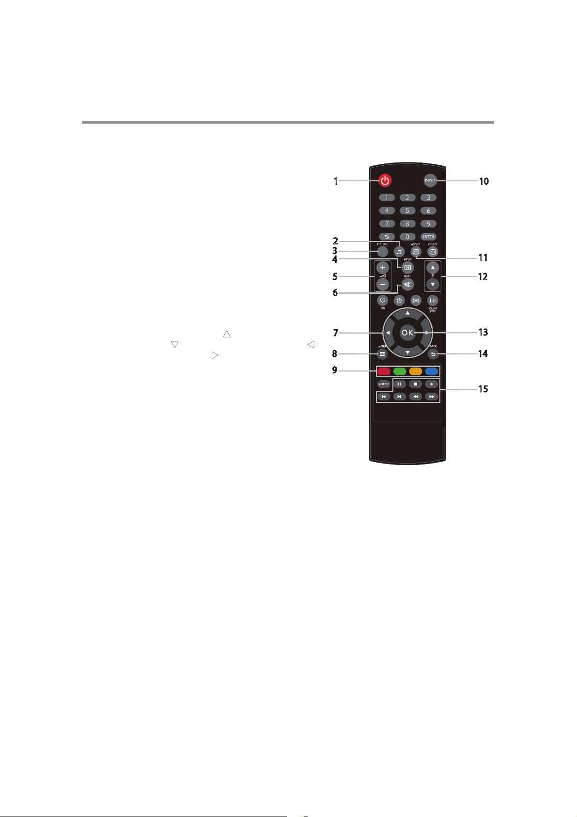
Infrared Remote Control
1 POWER button—Switches the power on/off. When the Power
indicator is not glowing red, no controls will work.
2 SOUND buttons—You can select [STANDARD], [DYNAMIC]
and [CUSTOM].
3 PICTURE button—Selects the picture mode from [DYNAMIC],
[ADVERTISER], [CUSTOM], and [STANDARD].
4 INFO button—Displays the current screen resolution and refresh
rate.
5 VOLUME buttons (VOL)—Pressing the plus (+) side increases
the audio output level. Pressing the minus (-) side decreases the
audio output level.
6 MUTE button—Switches the mute function on/off.
Chapter 1
Introduction
13
7 UP/DOWN/RIGHT/LEFT buttons—Moves the currently
highlighted area in the OSD menu. (S
highlighted area up, (T) moves the highlighted area down, (W)
moves the highlighted area left, (X) moves the highlighted area
right.
) button moves the
8 MENU button—Switches the OSD menu mode on/ off.
9 MEDIA CONTROL buttons—Contextual buttons providing
various media control functions in specific menus. Each button’s
functions will be shown in the OSD in corresponding colors.
10 INPUT button—Displays the OSD menu to switch the video
input. You can select [AV], [COMPONENT], [HDMI1],
[HDMI2], [DVI-D], [VGA], and [USB].
11 ASPECT button—Displays the current display aspect ratio.
12 INPUT button—Displays the OSD menu to switch the video input. You can select [AV], [COMPONENT],
[HDMI1], [HDMI2], [DVI-D], [VGA], and [USB].
13 OK button—Accepts the settings made in the OSD menu.
14 BACK button—Displays the previous OSD menu.
15 AUDIO/VIDEO CONTROL buttons—Provide control functions when playing media files. Fast reverse ( ),
play (), fast forward (), track backwards (), stop (), pause (), and track forward ().
Page 15
Chapter 1
30° 30°
N O T E
UTC/cppl!!Qbhf!25!!Uvftebz-!Nbz!35-!3127!!6;66!QN
14
Introduction
How to Use the Infrared Remote Control
Setting Up the Infrared Remote Control Sensor
Before using the infrared remote control, the LCD display’s remote control sensor
must be positioned. The remote control sensor is a small black box located on the
back of left of the LCD display. Press the small button near the base of the remote
control sensor, and slide the sensor away from the LCD display until it locks in place.
Reverse this procedure to return the sensor to its original position.
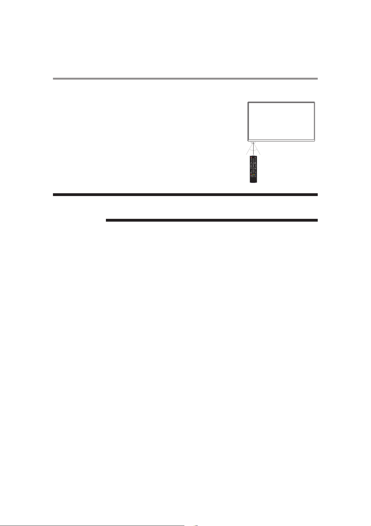
Operating Range of the Infrared Remote Control
Point the infrared remote control toward the LCD display’s remote control sensor
during button operation. Use the infrared remote control within a distance of about 10
m from the front of the LCD display’s remote control sensor and at a horizontal and
vertical angle of within 30° within a distance of about 10 m.
The remote control system may not function when direct sunlight or strong illumination
strikes the remote control sensor of the LCD display, or when there is an object in the path.
Page 16
UTC/cppl!!Qbhf!26!!Uvftebz-!Nbz!35-!3127!!6;66!QN
Handling the infrared remote control
• Do not subject to a strong shock.
• Do not allow water or other liquid to splash on the infrared remote control. If the infrared remote control gets wet,
wipe it dry immediately.
• Avoid exposure to heat and steam.
• Other than to install the batteries, do not open the infrared remote control.
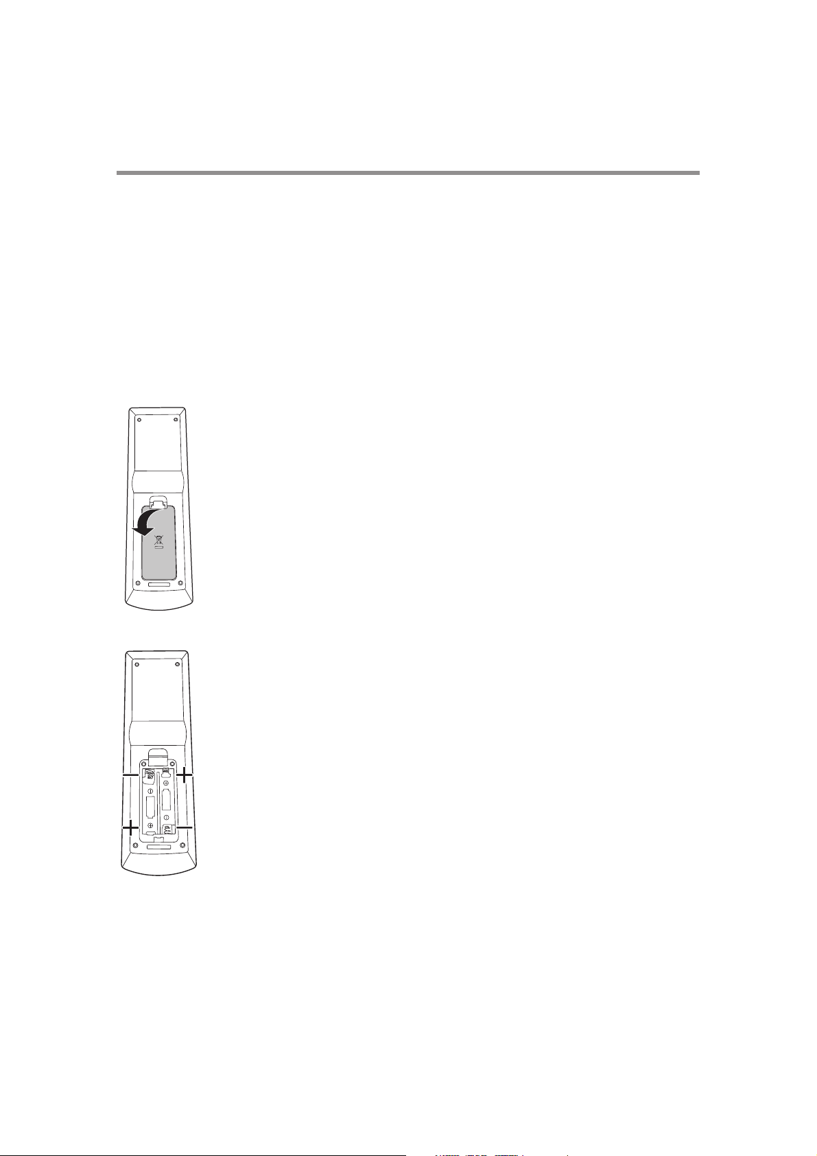
Installing and removing the infrared remote control batteries
The infrared remote control is powered by two 1.5 V AAA batteries.
How to install the batteries
1 Unlock and pull up the cover.
Chapter 1
Introduction
15
2 Align the batteries according to the (+) and (-) indications inside the case.
3 Replace the cover.
Page 17

Chapter 1
N O T E
UTC/cppl!!Qbhf!27!!Uvftebz-!Nbz!35-!3127!!6;66!QN
16
Introduction
How to remove the batteries
1 Unlock and pull up the cover.
2 Remove the batteries.
Incorrect use of batteries can result in leaks or explosion. Be especially careful of the following points.
• Place “AAA” batteries matching the (+) and (-).
• Do not mix battery types.
• Do not combine new batteries with used ones.
• Remove dead batteries immediately to prevent battery leakage
• Do not touch exposed battery acid, because it will cause damage to your skin.
• When the remote control no longer works at all, replace both batteries with new ones.
• If you do not use the remote control for a long time, replace both batteries with new ones.
Page 18
C A U T I O N
N O T E
C A U T I O N
N O T E
N O T E
UTC/cppl!!Qbhf!28!!Uvftebz-!Nbz!35-!3127!!6;66!QN
Chapter 2
Preparation for use
Preparation for installation
Determine the installation location
DO NOT ATTEMPT TO INSTALL THE LCD DISPLAY BY YOURSELF.
Installing your LCD display must be done by a qualified technician. Contact your dealer for
more information.
Proper operation of the display is not guaranteed when it is mounted upside down or face
down.
Lay the protective sheet, which was wrapped around the LCD display when it was packaged,
beneath the LCD display so as not to scratch the panel.
The LCD display requirements apply for equipment operating up to 2,000m above sea level.
Ventilation requirements for enclosure mounting
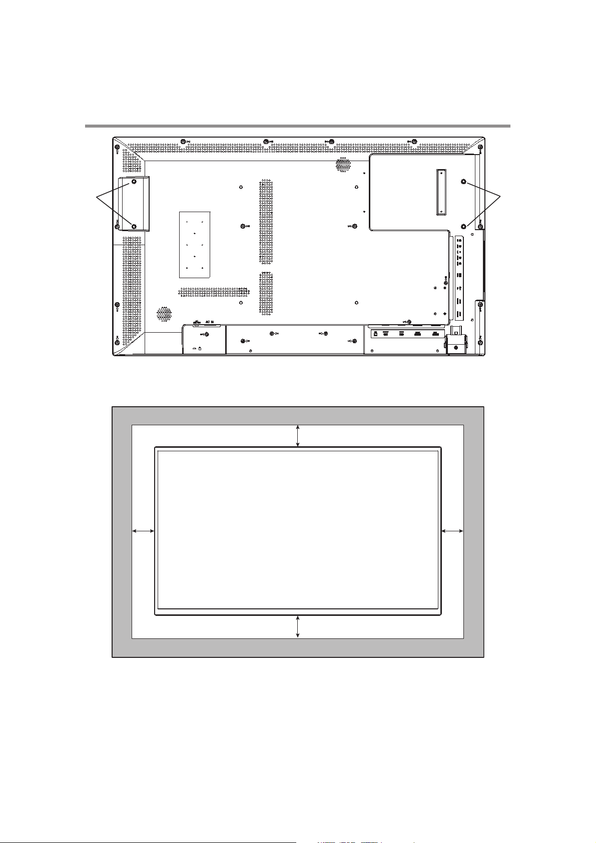
To allow heat to disperse, leave space around the display.
Don’t block the vents in the back of the display shown in the figure on the next page. If they
are blocked, heat accumulates inside the display, and can cause breakdown. The upper limit
of the operation guaranteed ambient temperature when the display is installed in the landscape position is 40°C (104°F). When installing the monitor in a case or an enclosure, ensure
adequate ventilation to keep the temperature inside the case is be 40°C (104°F) or below by
providing a cooling fan or ventilation holes in the case.
17
Page 19
Chapter 2
100 mm
100 mm
100 mm
100 mm
Don’t block the ventilation vents
1
1
(1) Screw holes for handles
UTC/cppl!!Qbhf!29!!Uvftebz-!Nbz!35-!3127!!6;66!QN
18
Preparation for use
Page 20

UTC/cppl!!Qbhf!2:!!Uvftebz-!Nbz!35-!3127!!6;66!QN
Preparation for use
Chapter 2
19
Using the wall mount or ceiling mount or handles
Lay the screen face down
Lay the protective sheet on a table, which was wrapped around the display when it was packaged, beneath the screen
surface so as not to scratch the screen surface.
This device cannot be used or installed without a mounting accessory. Failure to follow the correct mounting
procedures can result in damage to the product caused by improper installation. Failure to follow these
recommendations can void your warranty.
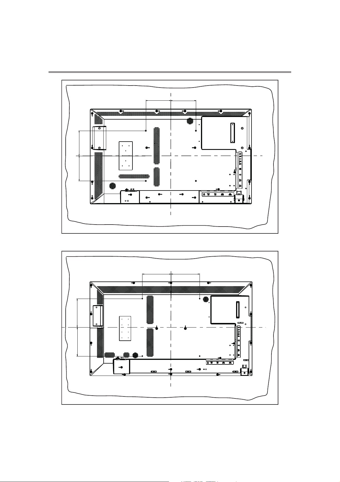
For installation, use M6 screws (with a Boss screw thread of at least 15mm, a loose-proof spring washer, and a length
10 mm longer than the thickness of the mounting bracket), and tighten them securely.
Secure handles (optional parts), using M6 screws with a length less than the thickness of the handle plus the allowable
depth of the screw holes (5mm for the 43” display, 9mm for the 50”/55” displays, and 6mm for the 65” display).
We recommend using a mounting interface that complies with VESA Requirements, TUV-GS or for North America
UL1678.
Page 21
Chapter 2
43”
200.00 mm 200.00 mm
200.00 mm200.00 mm
50”/55”/65”
UTC/cppl!!Qbhf!31!!Uvftebz-!Nbz!35-!3127!!6;66!QN
20
Preparation for use
150.00 mm150.00 mm
150.00 mm 150.00 mm
Page 22

UTC/cppl!!Qbhf!32!!Uvftebz-!Nbz!35-!3127!!6;66!QN
To prevent the display from falling:
• Install the display with metal brackets for wall or ceiling installation (commercially available) in your own responsibility. For detailed procedures of installation, refer to the
instructions of the metal brackets.
• To reduce the probability of injury and damage, be sure to consult the bracket manufacturer for installation location.
• To reduce the risk of falling in case of unexpected shocks, earthquakes or other disasters,
attach a rope to the left of the display and secure the rope to the wall display.
• The display may topple over or fall in case of earthquake or other disaster.
• Use stainless steel screws with enough strength to support the LCD display.
• With regard to the metal bracket:
• Use a VESA-compliant metal bracket (commercially available) that is strong enough to
• When using a bracket, do not block the heat dissipating holes in the display. See pages
• Before installation, make sure that the installation surface has sufficient strength.
• For details of the mounting procedure and the safe installation procedure, see the user
• Take measures such as using multiple metal brackets, holding the display at several
Preparation for use
hold the display.
17-18.
instructions of the metal bracket (commercially available) to be used.
points, and taking measures to prevent falling or dropping in case of a problem.
Chapter 2
21
Page 23
Chapter 2
N O T E
buttons
buttons
90°
Landscape
Portrait
Portrait
UTC/cppl!!Qbhf!33!!Uvftebz-!Nbz!35-!3127!!6;66!QN
22
Preparation for use
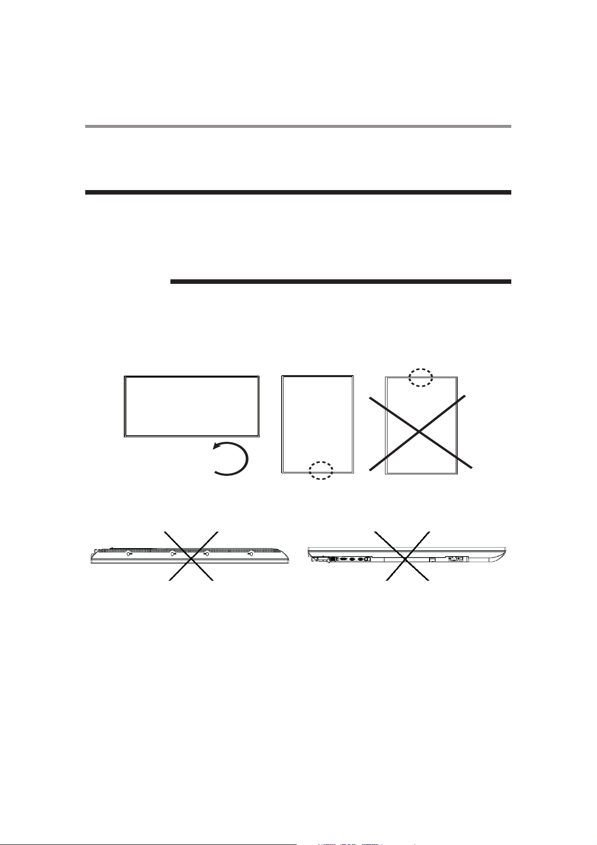
Installation in portrait or landscape orientation
The display can be installed in portrait or landscape orientation. Ensure that the display is oriented as shown in the
images in this section.
• The operating environmental condition (temperature) when the display is in portrait orientation is 0°C to 40°C (32° to 104°F).
• Proper operation of the display is not guaranteed when it is not mounted as shown below
(upside down, face down, etc.).
• In portrait or face-up orientation, the lifetime of the backlight is shorter than when in landscape orientation.
Installation in the portrait position
The buttons should be on the bottom side when viewed from the front of the display.
This display doesn’t have a function to rotate displayed images. To display images in the portrait orientation, use
already rotated images
Installing in the face-up position. Do not install in the face-down position.
Page 24

C A U T I O N
UTC/cppl!!Qbhf!34!!Uvftebz-!Nbz!35-!3127!!6;66!QN
Operation environment for portrait and face down (between 0° and 15°) installation
buttons
Preparation for use
Chapter 2
23
0~15°
The following operation environment details apply when the display is installed in portrait and face up orientations.
• Temperature 0 - 40°C / 32 - 104°F
• Humidity 20 - 80% (without condensation)
0~15°
Power connection instructions
1 Confirm Main Switch is off before making any connections.
2 Use an AC socket located near the display.
Avoiding Image Retention
Do not display static (non-moving) content on the display for long periods of time. This may
cause image “burn-in” or image retention, which is not covered under warranty.
Avoid Static Content
• Display dynamic (moving) images whenever possible.
• Turn off the display when not in use, or use the scheduling feature to turn the display off automatically at pre-set
times of the day.
Page 25

Chapter 2
N O T E
UTC/cppl!!Qbhf!35!!Uvftebz-!Nbz!35-!3127!!6;66!QN
24
Preparation for use
Connection procedure
Before making connections:
• First turn off the power of all the connected equipment before making connections.
• Refer to the user manual of each piece of equipment.
Please use a low resistance audio cable when the audio output terminal of the audio device
and PC is a stereo mini-jack. High resistance audio cables may affect audio levels, or mute
sound completely.
Page 26

UTC/cppl!!Qbhf!36!!Uvftebz-!Nbz!35-!3127!!6;66!QN
Connecting with an analog video source
Analog connection:
1 Connect a signal cable (VGA or YPbPr cable), to the VGA or AV IN connector.
2 Select AV, Component, or VGA using the SOURCE button on the LCD display, or the SOURCE button on the
infrared remote control. Once selected, the audio automatically switches to [LINE IN].
Audio connection:
• Connect an audio cable (ø3.5-mm stereo mini) (commercially available), to the LINE IN connector. Because the
audio automatically switches to [LINE IN], the audio is output simply by connecting the cable.
Preparation for use
Chapter 2
25
The display automatically distinguishes the timings shown in the table below, and sets the screen information. When a
PC or other device is connected, it automatically displays images properly. See “"Connecting with a digital video
source"” on page 26.
Page 27

Chapter 2
N O T E
UTC/cppl!!Qbhf!37!!Uvftebz-!Nbz!35-!3127!!6;66!QN
26
Preparation for use
Connecting with a digital video source
Digital connection:
• Connection via the HDMI IN connector
(1) Connect an HDMI cable (commercially available) to the HDMI1 IN or HDMI2 IN connector.
(2) Select [HDMI1] or [HDMI2] according to the connected connector by pressing the SOURCE button on the LCD
display or the HDMI1 or HDMI2 button on the infrared remote control.
• Connection via the DVI-D IN connector
(1) Connect a DVI-D cable (commercially available) to the DVI-D IN connector.
(2) Select [DVI-D] using the SOURCE button on the LCD display or the DVI-D button on the infrared remote control.
Second display connection:
• Connect the DVI-D OUT connector on the first display and the DVI-D IN connector on the second display using a
DVI-D cable (commercially available).
• The daisy chain connection allows up to 9 LCD displays to be connected (when using
2-meter cables. However, the maximum number of connectable LCD displays may be limited. It is recommended to check the number of connectable LCD displays in your installation environment in advance.
• Set the power off time using the POWER SAVE selection in the SETUP menu.
• Tiling mode can be used in HDMI1/2 for multi displays, if there is an external HDMI splitter equipped.
Audio connection:
• For HDMI 1/2/DVI-D, the default setting of audio source is a TMDS signal with HDMI/ DVI cable. Users can use
an external audio source if an audio cable (ø3.5-mm stereo mini) (commercially available) is connected to the
LINE IN connector. LINE IN” should be selected for the audio input source.
• To output the audio to the second display, connect the LINE OUT connector on the first display and LINE IN
connector on the second display using an audio cable (ø3.5-mm stereo mini) (commercially available).
Page 28

N O T E
UTC/cppl!!Qbhf!38!!Uvftebz-!Nbz!35-!3127!!6;66!QN
In this image the dashed lines around ports indicate connections OUT, and the small screen
at front indicates the second display.
Preparation for use
Chapter 2
27
Page 29

Chapter 2
N O T E
N O T E
UTC/cppl!!Qbhf!39!!Uvftebz-!Nbz!35-!3127!!6;66!QN
28
Preparation for use
Connecting LAN
Display connection using LAN
As shown in the illustration below, you can connect this display and a computer in network through a LAN hub.
Connect the display and the LAN hub using a straight type LAN cable (commercially available).
How to connect
• Turn off the main power switch of the computer and this display. If you make a connection while the power is on,
it the devices may fail.
• Connect the computer and the LAN hub using a straight type LAN cable (commercially available).
• Connect this display and the LAN hub using a straight type LAN cable (commercially available).
• When you connect two or more displays, you can connect the display and the LAN hub using a straight type LAN
cable (commercially available) as described above.
• When you use a cross type LAN cable (commercially available), you can connect the display and the computer one-to-one without using a LAN hub, however, the computer may
not be supported. It is recommended to check the operation in advance.
• If “LAN” control is selected, set “Standby Mode” to “Normal”; the power-on function with
LAN control will not work when Standby Mode is ECO.
Connecting the power cord to the display
Connecting the power source
Before making connections
1 Check that the main power switch is off.
Please refer to “Important Safety Instructions” and “Installation, Ergonomics, Care, and Service” in this manual for proper selection of the AC power cord. Use the clamper to prevent
accidental disconnection of the power cord.
2 Insert the power plug into the power outlet socket.
• Fully insert the prongs into the power outlet socket. Loose connections may cause noise.
• Don’t plug and unplug the power cord repeatedly in a short period of time.
Page 30

UTC/cppl!!Qbhf!3:!!Uvftebz-!Nbz!35-!3127!!6;66!QN
Preparation for use
Chapter 2
29
Page 31

30
Page 32

Chapter 3
31
How to use the LCD Display Monitor
Page 33

How to use the LCD Display Monitor
32
Chapter 3
Page 34

Chapter 3
33
How to use the LCD Display Monitor
Page 35

How to use the LCD Display Monitor
34
Chapter 3
Page 36

Chapter 3
35
How to use the LCD Display Monitor
Page 37

How to use the LCD Display Monitor
36
Chapter 3
Page 38

Chapter 3
37
How to use the LCD Display Monitor
Page 39

How to use the LCD Display Monitor
38
Chapter 3
Page 40

Chapter 3
39
How to use the LCD Display Monitor
Page 41

How to use the LCD Display Monitor
40
Chapter 3
Page 42

Chapter 3
41
How to use the LCD Display Monitor
Page 43

How to use the LCD Display Monitor
42
Chapter 3
Page 44

Chapter 3
43
How to use the LCD Display Monitor
Page 45

How to use the LCD Display Monitor
44
Chapter 3
Page 46

Chapter 3
45
How to use the LCD Display Monitor
Page 47

How to use the LCD Display Monitor
46
Chapter 3
Page 48

Chapter 3
47
How to use the LCD Display Monitor
Page 49

How to use the LCD Display Monitor
48
Chapter 3
Page 50

Chapter 3
49
How to use the LCD Display Monitor
Page 51

How to use the LCD Display Monitor
50
Chapter 3
Page 52

Chapter 3
51
How to use the LCD Display Monitor
Page 53

How to use the LCD Display Monitor
52
Chapter 3
Page 54

Chapter 3
53
How to use the LCD Display Monitor
Page 55

How to use the LCD Display Monitor
54
Chapter 3
Page 56

Chapter 3
55
How to use the LCD Display Monitor
Page 57

How to use the LCD Display Monitor
56
Chapter 3
Page 58

Chapter 3
57
How to use the LCD Display Monitor
Page 59

How to use the LCD Display Monitor
58
Chapter 3
Page 60

Chapter 3
59
How to use the LCD Display Monitor
Page 61

How to use the LCD Display Monitor
60
Chapter 3
Page 62

Chapter 3
61
How to use the LCD Display Monitor
Page 63

How to use the LCD Display Monitor
62
Chapter 3
Page 64

Chapter 3
63
How to use the LCD Display Monitor
Page 65

How to use the LCD Display Monitor
64
Chapter 3
Page 66

Chapter 3
65
How to use the LCD Display Monitor
Page 67

How to use the LCD Display Monitor
66
Chapter 3
Page 68

67
Page 69

68
Page 70

69
Page 71

70
Page 72

71
Page 73

72
Page 74

73
 Loading...