

Page 1

Acer Acer –LCD-BV203H
Service Manual
LCD Monitor Acer BV203H
- 0 -
Page 2

1
Table of Contents
Important Safety Notice ......................................................................................01
01 Product Specification .......................................................................................03
02 Flat Panel Specification ....................................................................................18
03 Exploded Diagram ............................................................................................37
04 Troubleshooting..................................................................................................39
05 Spare Parts List .................................................................................................44
06 Schematics and Layouts....................................................................................45
07 Assembly and Disassembly .............................................................................48
Appendix : User’s manual
Copyright
Copyright 2006 InnoLux Tech. Corp. Ltd
All Rights Reserved
This manual may not, in whole or in part, be copied, Photocopied, reproduced, translated, or
converted to any electronic or machine readable form without prior written permission of InnoLux
Tech. Corp. Ltd.
Acer BV203H Service Manual
1
Page 3

Acer Acer –LCD-BV203H
Important Safety Notice
1. Safety precautions
This monitor is manufactured and tested on a ground principle that a user’s safety comes first.
However, improper used or installation may cause damage to the monitor as well as to the
user.
Warning:
z This monitor should be operated only at the correct power sources indicated on the label
on the rear of the monitor. If you’re unsure of the power supply in you residence, consult
your local dealer or Power Company.
z Do not try to repair the monitor by yourself, as it contains no user-serviceable parts. This
monitor should only be repaired by a qualified technician.
z Do not remove the monitor cabinet. There are high-voltage parts inside that may cause
electric shock to human bodies.
z Stop using the monitor if the cabinet is damaged. Have it checked by a service technician.
z Put your monitor only in a lean, cool, dry environment. If it gets wet, unplug the power
cable immediately and consult your closed dealer.
z Always unplug the monitor before cleaning it. Clean the cabinet with a clean, dry cloth.
Apply non-ammonia based cleaner onto the cloth, not directly onto the class screen.
z Do not place heavy objects on the monitor or power cord.
2. Product safety notice
Many electrical and mechanical parts in this chassis have special safety visual inspections
and the protection afforded by them cannot necessarily be obtained by using replacement
components rated for higher voltage, wattage, etc. Before replacing any of these components
read the parts list in this manual carefully. The use of substitute replacement parts, which do
not have the same safety characteristics as specified in the parts list, may create shock, fire,
or other hazards.
3. Service notes
z When replacing parts or circuit boards, clamp the lead wires around terminals before
soldering.
z Keep wires away from high voltage, high temperature components and sharp edges.
z Keep wires in their original position so as to reduce interference.
z Adjustment of this product please refers to the user’ manual.
2
Page 4
Acer Acer –LCD-BV203H
V
Y
01 Product Specification
1. General:
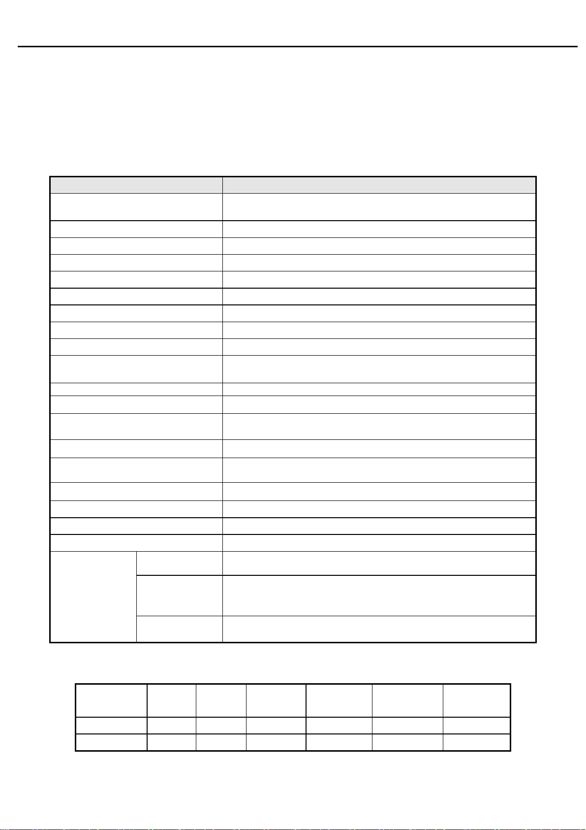
Acer BV203H is designed with LVDS interface and dual (analog and digital signal) input, it featured with embedded universal
AC power supplies and audio input. It’s a green product and meets all ROHS standard. The power button and display control
buttons are on the front of the monitor. The monitors shall automatically to display lower resolution video modes into
1600x900 full screen display. The image can be adjusted through OSD control.
1.1 Main Features
Features Specifications
Panel source
Maximum resolution
Back light system 4 CCFL (top & bottom edge side)
Actual Resolution display 1600 x 900
Pixel pitch
Display area 442.8 ( H ) x249.075 ( V )
Contrast ratio
Response time (Tr+Tf) 5ms (typ.),
Viewing angle
Input interface
Audio-In Reserved
Earphone NO
Speakers Reserved
Video Signal Inputs D-sub, DVI-D
Knobs and Indicators
Security Features Kensington® lock port, VESA® Wall-mountable interface, 100 mm
Power switch button, MENU button, Auto button, eColour, Down
80°(L)/ 80°(R), 80°(U)/80°(D) typ. CR>=10)
0.2768(H) mmx 0.2768(V)mm
׃1 (typ.),600׃1(min.)
1000
Analog(D-sub 15 pin)
Digita(DVI-D connector )----option
button, Down button
LTM200KT01
1600 x 900
Power management Compatible with VESA,EPA,NUTEK,DPMS
Plug & Play
University AC power supply
For Non-EMEA
OSD language
For EMEA
1.2 Accessories
Items
Description
VGA
cable
1.8m 1.8m Multi English
● ● ● ●
2. Operation Specifications
Russia
DVI
cable
English (US), French, Italian, Finnish, Spanish, German, Dutch,
English (US)
English (US), French, Italian, Finnish, Spanish, German, Dutch,
, French, Italian, Simplified Chinese, Spanish, German a
Dutch, Traditional Chinese, Japanese
User’s
manual
Warranty
card
Quick-start
Guide
Installation
Guide
ESA
ES
Russian
Russian
3
Page 5
Acer Acer –LCD-BV203H
The unit should suffer no visible cosmetic damage and should operate with no degradation in display quality during
exposure to the operating conditions and after exposure to the non-operating conditions, in any sequence.
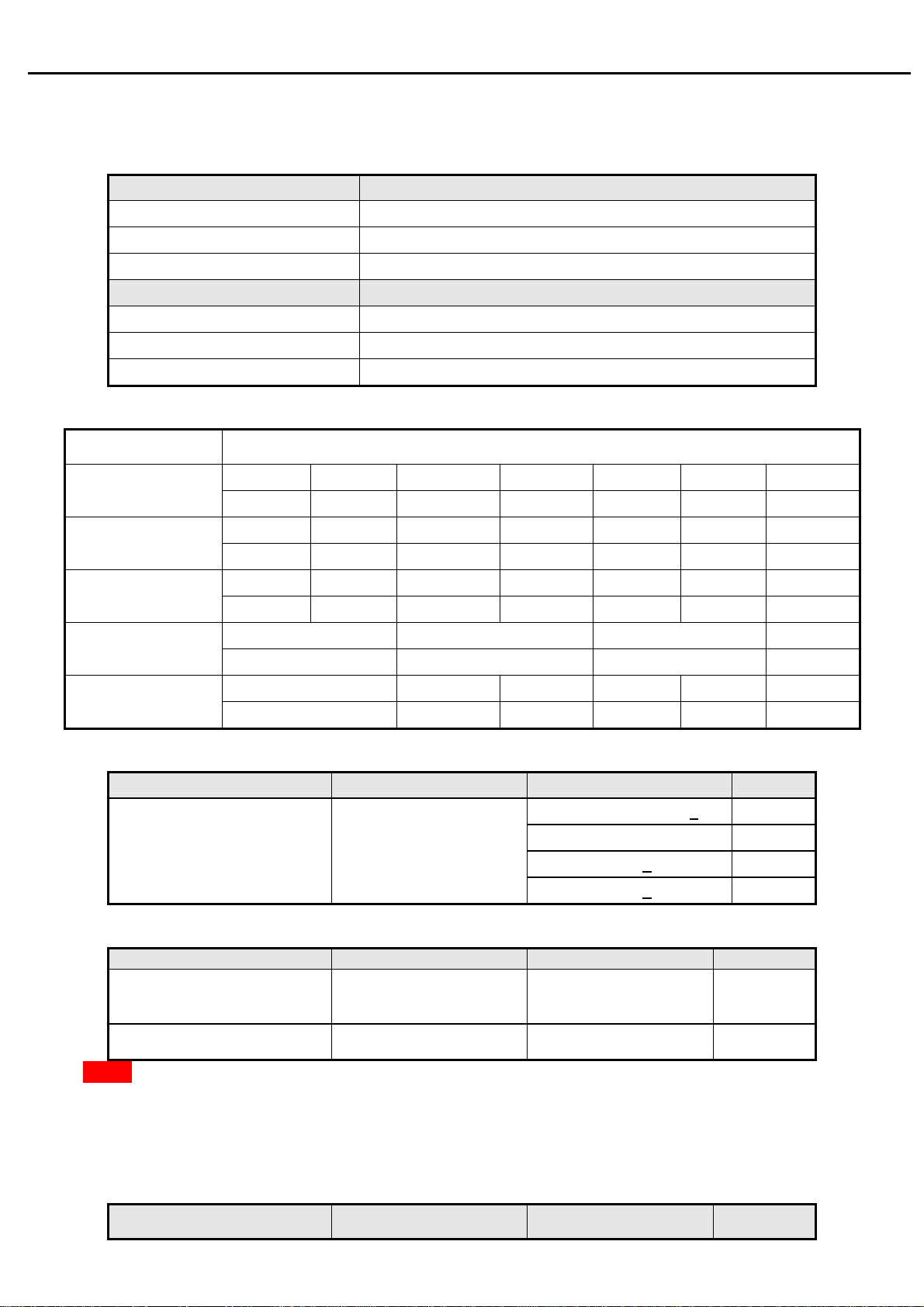
2.1 Environmental conditions
Operating Specification
Temperature range
Relative humidity 20% to 80%
Altitude 0 to 3048M (10000 ft)
0°C to 40°C
Storage
Temperature range
Relative humidity 5% to 80%
Altitude 0 to 9144M (30000 ft)
-25°C to 60°C
2.2 Safety, EMC, Ergonomics and Compatibility Requirements
Items Description
UL/cUL CB TUV/GS CCC Other
Safety
● ● ● ●
FCC CE CCC VCCI-B
EMC
● ● ● ●
TCO99 TCO03
Ergonomics
● ●
Compatibilit
y
Power
Managemen
Windows
● ● ● ●
Energy Star
●
Windows 2000 Windows XP vista
2.3 Electrostatic Discharge Requirements
Item Condition Spec
Contact discharge : +4KV
Contact discharge :
Electrostatic Discharge IEC61000-4-2(EN55024)
Air discharge : + 8KV
Air discharge : +15KV
2.4 Reliability
Items Condition Spec Note
MTBF
CCFL Life time Luminance becomes 50%
Note1. Display an all WHITE field at mid Brightness and Contrast settings.
50,000 Hours
≧
≧ 40,000 Hours(min)
3. Electrical and Optical Characteristics and Performance
3.1 Main Power Supply
3.1.1 Input characteristics
●
●
Excluding
the LCD,
CCFL
Note1
Items Condition Spec Note
4
Page 6
Acer Acer –LCD-BV203H
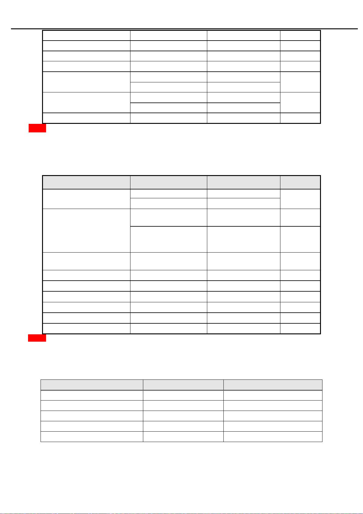
AC Input Voltage range
AC Input Voltage rating Universal input full range 100~240Vac
AC input frequency range 90~264Vac 47~63Hz
AC input frequency rating 100~240Vac 50~60Hz
Universal input full range 90~264Vac
100Vac 1.2A(max) AC Input Current
240Vac 0.6A(max)
Inrush Current
100Vac,cold star,25°C 40A (max)
240Vac,cold star,25°C 60A(max)
AC-DC power Efficiency
Note2. Before each test, the buck capacitor need to be discharged.
Before each test, it must be 10 minutes at least after the latest test.
Hot star not component be damaged.
3.1.2 Output characteristics
Items Condition Spec Note
Ripple and Noise
DC Output Voltage
DC output loading capability
Rise Time
Dynamic load change
Hold-up time
Overshoot
Turn on delay time
DC output full loading ≥75%
+16V output <800mv
+5V output <500mv
16v loading:0.3A~2.0A
5v loading:0.75A~1.5A
5v loading:0.04A~1.5A
16V loading: 0A
Vcc5V/1.5A,
<20mS
AC input: 100V~240V >10mS
<10%
2S
Vcc16V:15.2V~17.6V
Vcc5V: 4.95V~5.45V
Vcc16V: 15.2V~20V
Vcc5V: 4.95V~5.45V
Vcc16V/2.0A
See Note2
See note 3
For system
active
For power
saving or DC
off
Power management See Table-1
Note3: Paralleled a 0.1uF ceramic Cap. And 47uF aluminum Cap. Between the end of DC loading side,
Measured band-width=20MHz.
3.1.3 Protection characteristics
Protection Condition Spec
OCP(Over current protection) nominal AC input 50W ( min )
SCP(short circuit protection)
OVP(Over voltage protection)
OTP(Over temperature
Fuse protection
with auto-recovery
5
Page 7
Acer Acer –LCD-BV203H
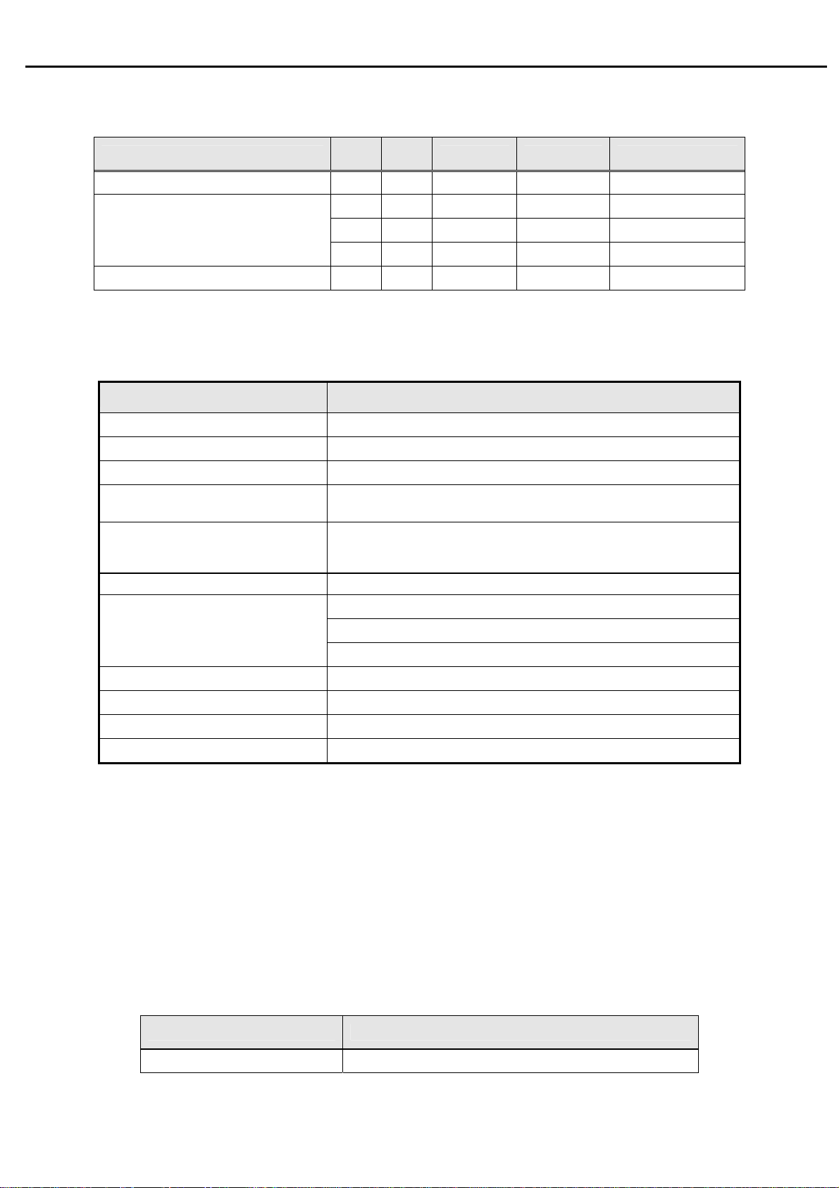
Table-1
Status
Power On on on active
Power Saving
Power Off -- -- -- < 1W Off
3.2 Backlight Power Supply
: LTM200KT01
Panel
Items Specification
H-sy
nc
V-s y
nc
off on blanked < 2W Amber
on off blanked < 2W Amber
off off blanked < 2W Amber
Video Power LED
≤ 45W
BLUE
Lamp
Input Voltage 15.2V~18.2V
Input current
On/Off switch level
Brightness PWM duty
CCFL operating Voltage
CCFL Current
CCFL startup voltage
Operating frequency 40~80 KHz
Protect delay time
Efficiency
3.2 Brightness output
4 CCFL
1.6A (Typ.), 2.0A (Max.)
5.5V≧Von≧ 2.0 V (on)
-0.3v ≤ Voff ≤ 0.8 V (off)
35%~100%
PWM:High=3.3V(3.0~3.6V),Low=0.0V
840Vrms (Typ.),
2.0 mA (min.)(With PWM Dim)
6.5mA (Typ.)
mA (Max.)
8.0
≧1700 Vrms (0˚C)
> 1 second
≥70%(with dummy load)
The test to verify specifications in this section shall be performed under the following standard conditions unless
otherwise noted.
Temperature : 25 ± 5°C
Test pattern : white
Video Resolution : 1600 x 900
Video input level : 700 mV ± 2%
Warm-up time : 30 minutes
LCD Module BL
LTM200KT01 >=250 cd/m2
Set brightness control and also contrast control at maximum, to measure the screen center, the light output shall ≥
BL cd/m
2
(as panel spec)
6
Page 8
Acer Acer –LCD-BV203H
3.3 White balance
Mode
Cool 9300K 0.283 ± 0.030 0.297 ± 0.030
Warm 6500K 0.313 ± 0.030 0.329 ± 0.030
User Panel While x Panel While y
The test standard conditions refer to Sec 3.3. (Brightness and contrast are under default value)
Chromaticity Coordinate
x y
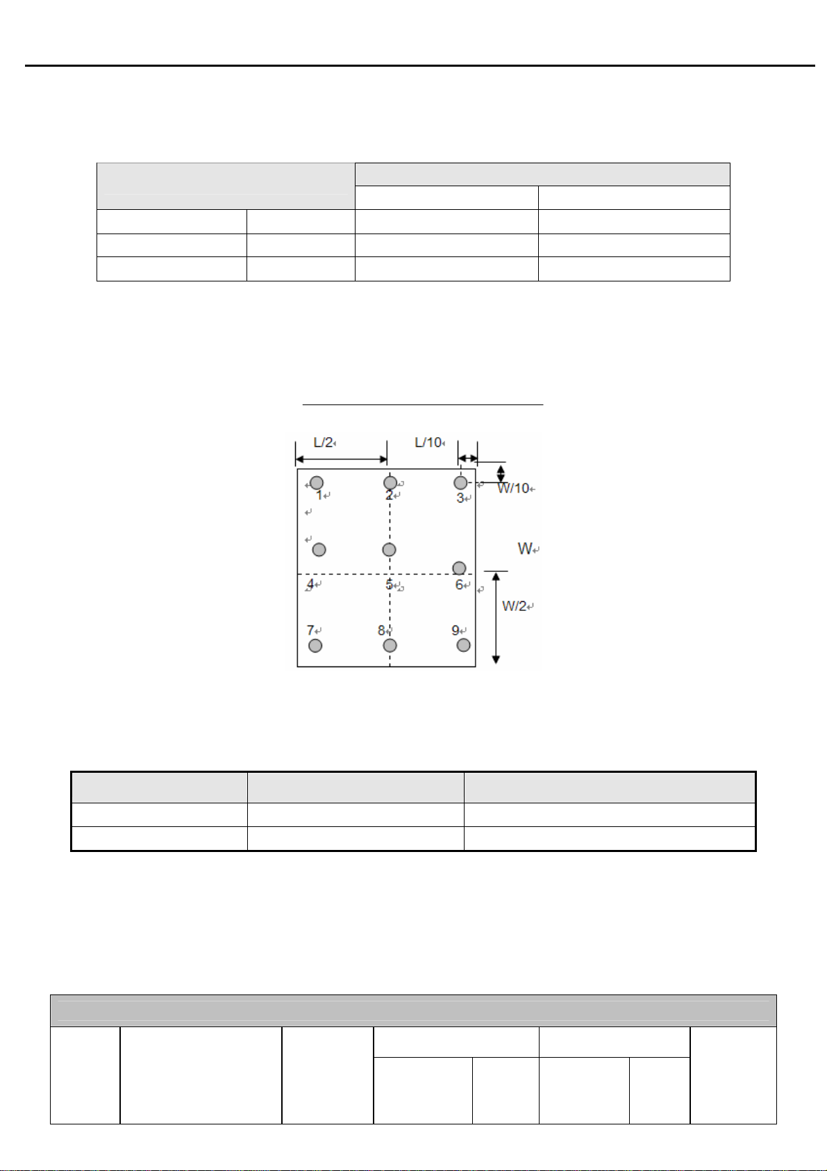
3.4 Brightness uniformity
The test standard conditions refer to Sec 3.3.
)(backlight points nine of luminance Min.
)(backlight points nine of luminance Max.
%≥75
4. Input / Output Signal Specifications
4.1 Video signals
Items Condition Specification
Analog RGB signal
Sync
4.2 Signal Timing
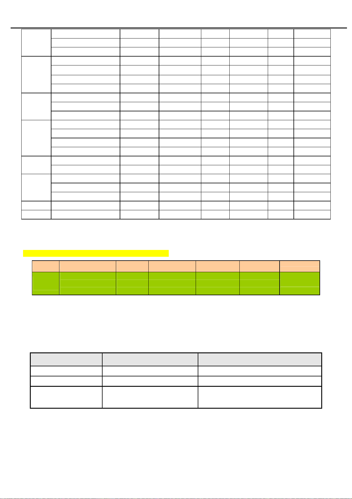
4.2.1
D-SUB Inputs
Through D-SUB connectors, this unit can support F
modes as below:
Mode Resolution Total
Input impedance = 75 Ohm 0.7Vp-p
Input impedance ≧ 1k Ohm
TTL level, Separate H/V-sync(+/-)
= 31.5 ~ 80 KHz, Fv=55 ~ 75Hz and SXGA display
H
VESA MODES
Horizontal Vertical
Nominal
Frequency
+/-0.5KHz
Sync
Polarity
Nominal
Frequency
+/-1Hz
Sync
Polarity
Nominal
Pixel Clock
(MHz)
7
Page 9
Acer Acer –LCD-BV203H
640*480@60Hz 800*525 31.469 N 59.941 N 25.175
VGA
SVGA
XGA
VESA
SXGA
MAX
WXGA 1280*800@60Hz 1680*831 49.702 N 59.810 P 83.500
WXGA+ 1600x900@60Hz 2122x934 55.99 N 59.946 P 118.250
640*480@72Hz 832*520 37.861 N 72.809 N 31.500
640*480@75Hz 840*500 37.500 N 75.000 N 31.500
800*600@56Hz 1024*625 35.156 P 56.250 P 36.000
800*600@60Hz 1056*628 37.879 P 60.317 P 40.000
800*600@72Hz 1040*666 48.077 P 72.188 P 50.000
800*600@75Hz 1056*625 46.875 P 75.000 P 49.500
1024*768@60Hz 1344*806 48.363 N 60.004 N 65.000
1024*768@70Hz 1328*806 56.476 N 70.069 N 75.000
1024*768@75Hz 1312*800 60.023 P 75.029 P 78.750
1152*864@75Hz 1600*900 67.500 P 75.000 P 108.000
1280*960@60Hz 1800*1000 60.000 P 60.000 P 108.000
720x400@70Hz 900*449 31.469 N 70.087 P 28.322
1280*720@60Hz 1650x750 44.955 N 59.940 P 74.176
1280*1024@60Hz 1688*1066 63.981 P 60.020 P 108.000
1280*1024@75Hz 1688*1066 79.976 P 75.025 P 135.000
832*624@75Hz 1152*667 49.725 N 74.550 N 57.283
864*525
35.000 P
66.667 P 30.240
Note: 1. Non-interlace signals only (An interlace signal cannot be display)
2. Please refer to F/W specification for more detail
3. Each frequency of Power Macintosh and Sun Ultra is a reference value
For DVD Player Input, Attached timing is supported: (Optional)
Mode Resolution (active dot)
DVD
Player
480P@60Hz 858x525 31.5 60.000 27.027
576P@50Hz 864x625 31.250 50.000 27.000
720P@60Hz 1650x750 45.000 60.000 74.250
Resolution
(total dot)
Horizontal
Frequency (KHz)
Vertical
Frequency (Hz)
4.2.2 Digital signals
TMDS Signal: (min) ±200mVpp@24Bit
4.2.3 DDC signals
DDC signals: 5V@50mA TTL level
4.3 Timing requirements
Scan Frequency Condition Specification
Horizontal
Vertical
Out of range
Sync polarity: (+) or (-)
Sync polarity: (+) or (-)
Excluding
Horizontal 31.5~80 KHz or
Vertical 55-75 Hz
31.5 ~ 80 KHz.
55-75Hz
Message “Input Not Supported” on screen
Nominal Pixel
Clock (MHz)
Remark
4.4 DDC data
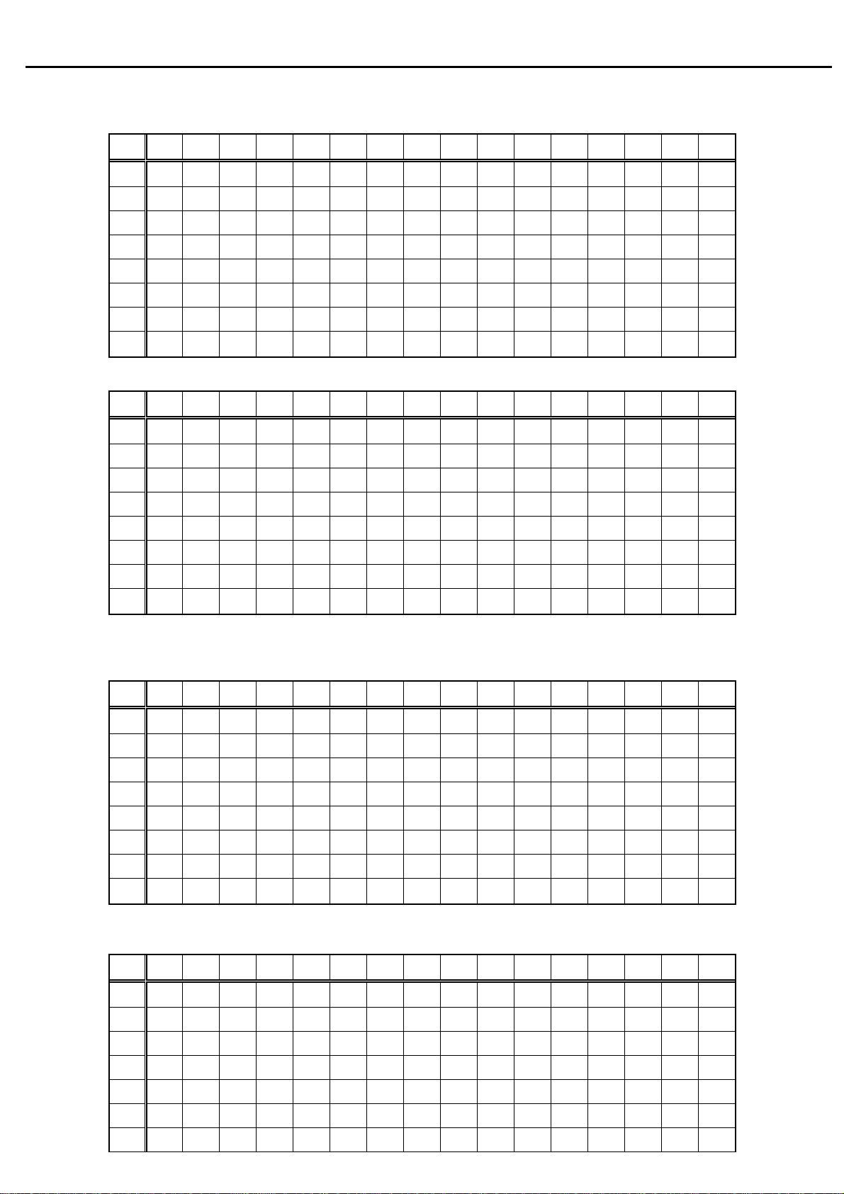
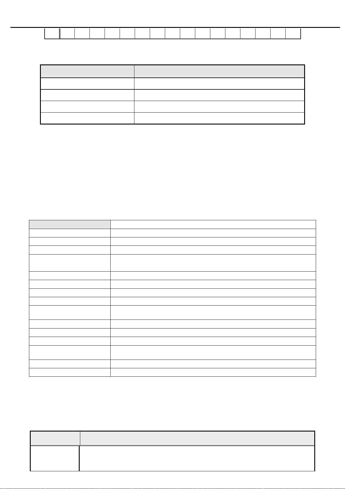
4.4.1 EDID Standard Compliance
EDID File Format : VESA’s EDID Standard Version #3, Revision #0,
EDID Structure : Version #1, Revision #3.
EDID Data Table : See the attached table (for example)
8
Page 10
Acer Acer –LCD-BV203H
B203H VGA EDID table
0 1 2 3 4 5 6 7 8 9 A B C D E F
0 00 FF FF FF FF FF FF 00 04 72 94 00 00 00 00 00
1 00 00 01 03 08 2C 19 78 EA DE 95 A3 54 4C 99 26
2 0F 50 54 BF EF 80 71 4F 81 40 81 80 81 C0 81 00
3 01 01 01 01 01 01 31 2E 40 00 62 84 22 30 58 A8
4 35 00 BB F9 10 00 00 1D 00 00 00 FD 00 37 4B 1F
5 50 0C 00 0A 20 20 20 20 20 20 00 00 00 FF 00 30
6 30 30 30 30 30 30 30 30 30 30 30 0A 00 00 00 FC
7 00 42 32 30 33 48 0A 20 20 20 20 20 20 20 00 CS
B203H DVI EDID table
0 1 2 3 4 5 6 7 8 9 A B C D E F
0 00 FF FF FF FF FF FF 00 04 72 94 00 00 00 00 00
1 00 00 01 03 80 2C 19 78 EA DE 95 A3 54 4C 99 26
2 0F 50 54 BF EF 80 71 4F 81 40 81 80 81 C0 81 00
3 01 01 01 01 01 01 31 2E 40 00 62 84 22 30 58 A8
4 35 00 BB F9 10 00 00 1D 00 00 00 FD 00 37 4B 1F
5 50 0C 00 0A 20 20 20 20 20 20 00 00 00 FF 00 30
6 30 30 30 30 30 30 30 30 30 30 30 0A 00 00 00 FC
7 00 42 32 30 33 48 0A 20 20 20 20 20 20 20 00 cs
V203H VGA EDID table
0 1 2 3 4 5 6 7 8 9 A B C D E F
0 00 FF FF FF FF FF FF 00 04 72 95 00 00 00 00 00
1 00 00 01 03 08 2C 19 78 EA DE 95 A3 54 4C 99 26
2 0F 50 54 BF EF 80 71 4F 81 40 81 80 81 C0 81 00
3 01 01 01 01 01 01 31 2E 40 00 62 84 22 30 58 A8
4 35 00 BB F9 10 00 00 1D 00 00 00 FD 00 37 4B 1F
5 50 0C 00 0A 20 20 20 20 20 20 00 00 00 FF 00 30
6 30 30 30 30 30 30 30 30 30 30 30 0A 00 00 00 FC
7 00 56 32 30 33 48 0A 20 20 20 20 20 20 20 00 cs
V203H DVI EDID table
0 1 2 3 4 5 6 7 8 9 A B C D E F
0 00 FF FF FF FF FF FF 00 04 72 95 00 00 00 00 00
1 00 00 01 03 80 2C 19 78 EA DE 95 A3 54 4C 99 26
2 0F 50 54 BF EF 80 71 4F 81 40 81 80 81 C0 81 00
3 01 01 01 01 01 01 31 2E 40 00 62 84 22 30 58 A8
4 35 00 BB F9 10 00 00 1D 00 00 00 FD 00 37 4B 1F
5 50 0C 00 0A 20 20 20 20 20 20 00 00 00 FF 00 30
6 30 30 30 30 30 30 30 30 30 30 30 0A 00 00 00 FC
9
Page 11
Acer Acer –LCD-BV203H
7 00 56 32 30 33 48 0A 20 20 20 20 20 20 20 00 cs
4.5 Audio signal
Items Specification
Input impedance
Frequency response range
Signal to noise ratio
Output power
≧ 10K ohm
200Hz – 10kHz
≧ 40 dB
≧ 1.0 W + 1.0W ( 10%THD )
5. Function Specifications
All the tests to verify specifications in this section shall be performed under the following standard conditions unless
otherwise noted. The standard conditions are:
Temperature : 25 ± 5°C
Warm-up time : 30 minutes minimum
Checking display modes : All the specified modes
5.1 Panel general specifications
5.1.1
General
Supplier
Model name
Display Area 442.8 ( H ) x249.075 ( V )
Pixel Pitch 0.2768(H) mmx 0.2768(V)mm
specifications
SEC
LTM200KT01
Display Colors: 16.7 Million (6-bit + HI-- FRC)
Number of Pixel
Pixel Arrangement RGB vertical stripe
Brightness 300cd/m2 (Typ.) 250cd/m2 (Min.)
Contrast Ratio
Viewing Angle
Display Mode Normally White
Frame rate
Response Time Tr + Tf = 5ms Typical
Surface Treatment
Lamp 4 CCFL
Outline Dimension
5.1.2
LCD module defects
LCD module defects check follow to the IIS.
1600x900 pixels
1000
׃1 (typ.)
Hor:160°, Ver: 160°
(Typical, CR>10)
60Hz
Anti-glare, Haze = 25%, Hard coating (3H)
463.3(W)x272.5(H)x17.5(D) Max
5.2 Keypad Function
5.2.1
Control buttons on the front bezel
CONTROL KEY KEYS FUNCTION
A. When OSD un-displays, press [AUTO] to perform auto-adjustment
[AUTO]
B. When OSD displays, press [AUTO] to return to previous level menu
C. When “e Color OSD” OSD displays, press [AUTO] to exit the OSD
10
Page 12
Acer Acer –LCD-BV203H
A. When OSD isn’t shown on screen, press [MENU] to enter OSD interface. The
OSD interface uses “ACER e Color Management” and “User” to instead
“Contrast” and “Brightness” separately. When press “ACER e Color
Management” to show “e Color OSD”, and press “User” to show OSD interface
5.2.2
[MENU]
[►], [◄]
[e Color ]
[POWER] Power on or power off the monitor
Hot Key Operation
before. The translations of “ACER e Color Management” and “User” are always
English.
B. When OSD displays, press [MENU] to perform function of menu icon that is
highlight or enter next level menu
A. When “MENU OSD” displays, press these keys to change the contents of an
adjustment item, or change an adjustment value
B. When “MENU OSD” un-displays, if it is with audio, press [►] to show “Audio”
OSD and increase the volume, press [◄] to show “Audio” OSD and decrease
the volume; else it has no use to press these keys.
A. When OSD un-displays, press [e Color] to show “e Color OSD”, and press again
the OSD can not disappear, but the time of “e Color OSD” disappearing is reset
10 second again.
B. When OSD disappear not including “e Color OSD”, press [e Color] to show “e
Color OSD” OSD, the OSD before disappears, but the parameters of it should be
saved
HOT KEY OPERATION
FUNCTION
AUTO
e Color
◄
MENU POWER
►
Press [e Color ]
, and then press
[POWER] for DC power on.
FACTORY MODE
●
ON
OSD menu will be shown with
“F” on the left top. Select “F”
for entering factory mode.
5.3 OSD Structure
The On-Screen Display (OSD) shall be an easy to use icon based menu through keypad OSD buttons or remote control unit. The
unit shall leave the factory with all OSD controls set to their default values.
First Second Third Control Range Default Value
Brightness
ACER e COLOR
Management
User
Empowering
Technology
User mode
Text mode 50
Contrast
Standard
Graphics
Movie mode 56
Brightness
11
User mode
50
50
60
77
Page 13
Acer Acer –LCD-BV203H
Image
Position
Color
Language
Focus
Clock
Horizontal
Vertical
Warm (6500K)
Cool (9300K)
User
NO-EMEA EMEA
English English
Deutsch Deutsch
Español Español
简体中文
繁體中文
Français Français
Italiano Italiano
日本語
Hollands
Русский
Suomalai
nen
ACM
---
---
---
---
--- ---
--- ---
Red
Green
Blue
--- ---
--- ---
--- ---
--- ---
--- ---
--- ---
--- ---
--- ---
0 ~ 100
0 ~ 100
0 ~ 100
0 ~ 100
0 ~ 100
0 ~ 100
0 ~ 100
Text mode 44
Standard
Graphics
Movie mode 77
OFF
Depend on each timing
50 ○1
50
Depend on each timing
80
80
80
English
77
97
Hor. Position
OSD
Input (Dual)
Input (Analg
only)
Info
Reset
Exit
Notes; ○1 Clock default 50 is for Visa timing. Others depend on timing.
Ver. Position
OSD Timeout
Analog
Digital
DDCCI ON/OFF
DDCCI ON/OFF
Resolution
H. Freq
V. Freq
S/N
Analog/Digital Input
--- --- --- ---
--- --- --- ---
---
---
---
--- --- ---
--- --- -- ON
ON
--- --- ---
--- --- ---
--- --- -- ETL000….0000(22)
0 ~ 100 50
0 ~ 100 50
10~ 120 20
12
Page 14
Acer Acer –LCD-BV203H
6. SOP of PCBA ISP Programming
6.1 Operational condition:
Equipment: PC, ISP card, signal cable and power cable.
ESD requirements: antistatic wrists, antistatic gloves (fingers), and connecting cable
Name of ISP program: ISP_Tool_v3.7.5.3
Manufacture of FW IC:PMC/SST/MX
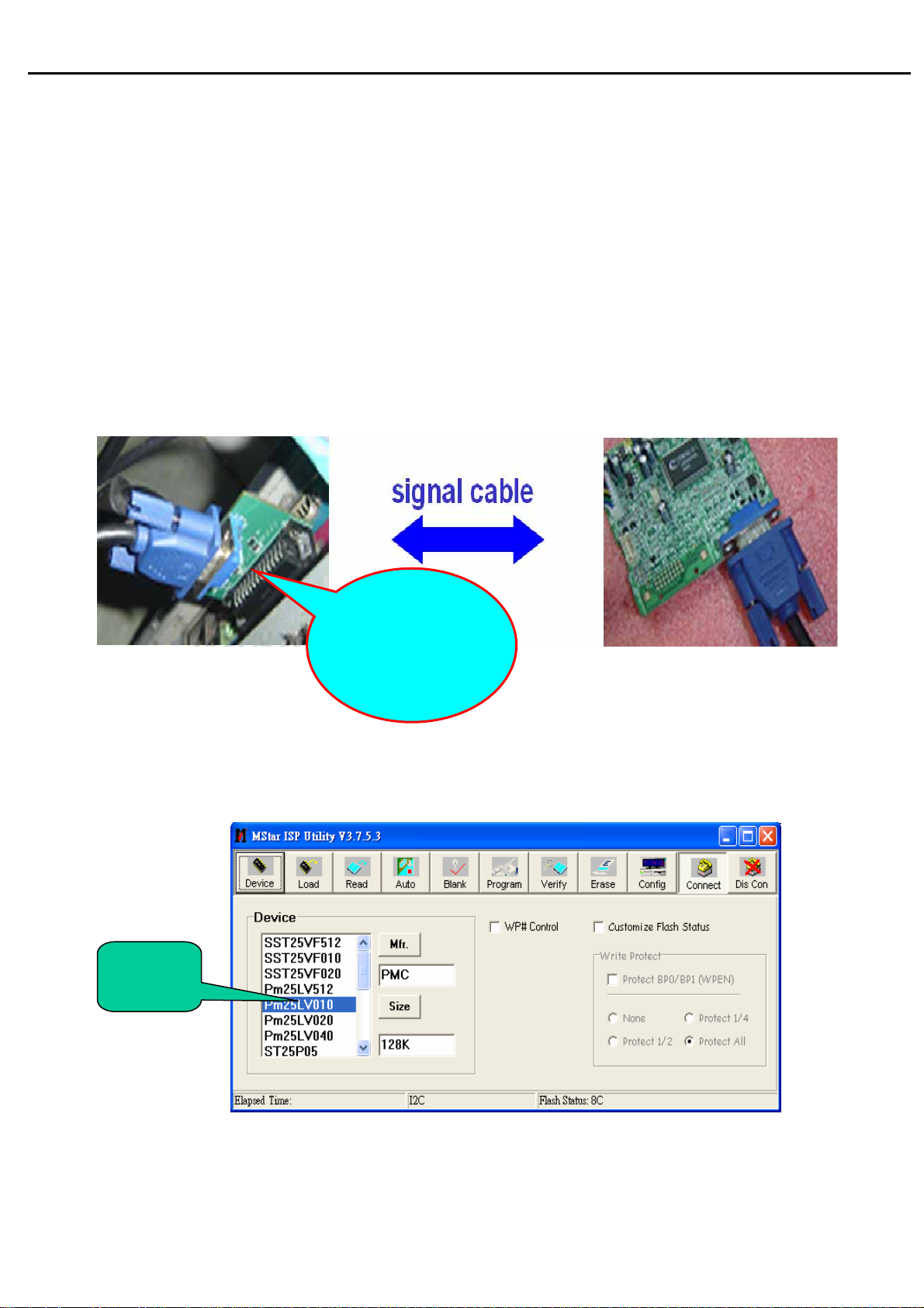
6.2 Operational steps:
1.Connection: connect PC to PCBA with signal cable, and then keep AC and DC in open state
One port of ISP
program card
is connected to
PC print port.
2. Adjust ISP programming
Firstly, double click ISP_Tool_v3.7.5EXEI and open ISP program, then select “Device”, next
select manufacturer model of FW IC, which should be correspondent with that of PCBA FW IC.
Double click Figure One.
FW IC
Model
13
Page 15
Acer Acer –LCD-BV203H
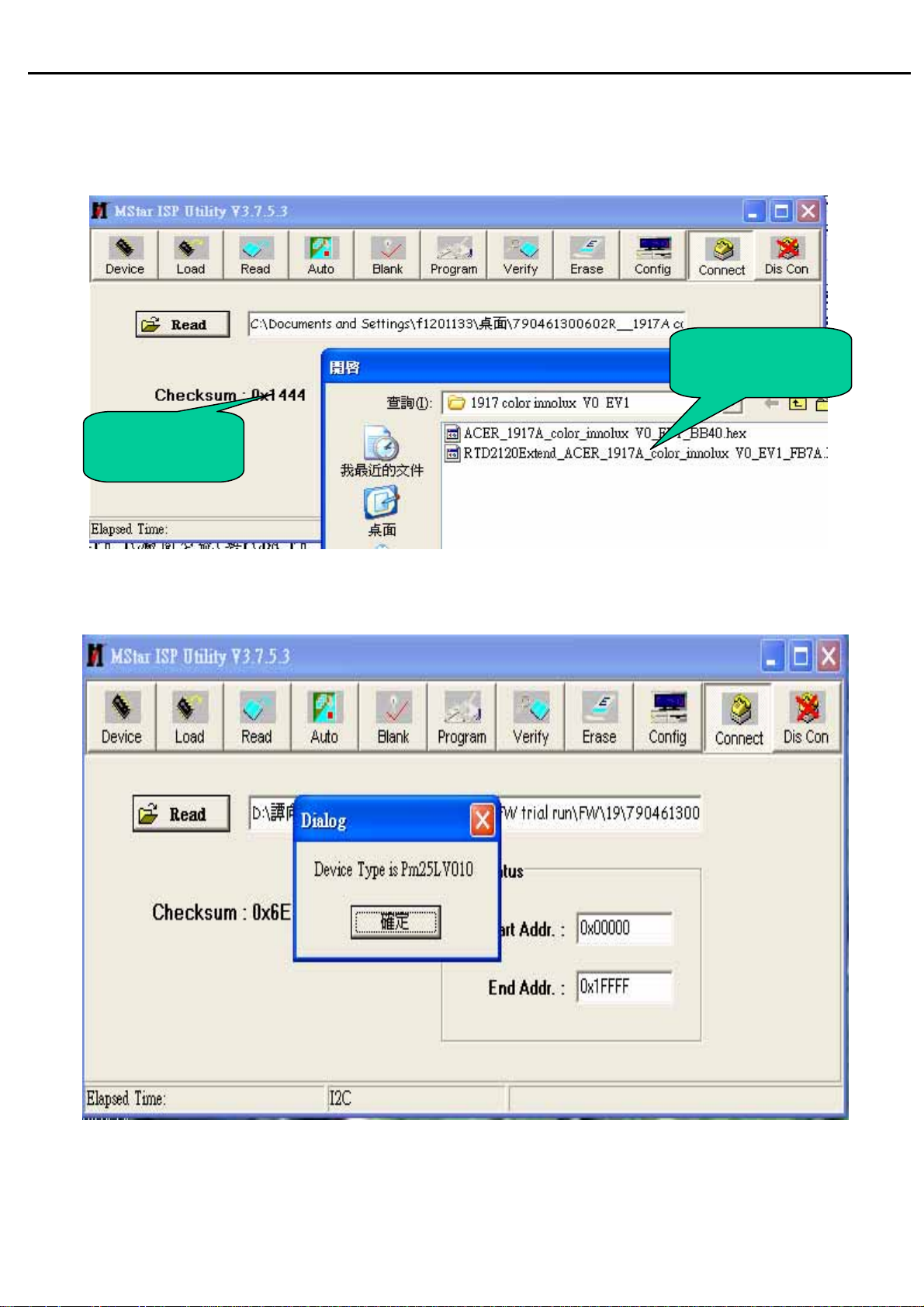
r
Secondly﹐download FW software: first select “READ”, and then load FW software in Rooter
(Fig.2).
FW software
roote
Software
Checksum
Thirdly, select “Connect” and enter ISP MODE as in the following Figure 3.
14
Page 16
Acer Acer –LCD-BV203H
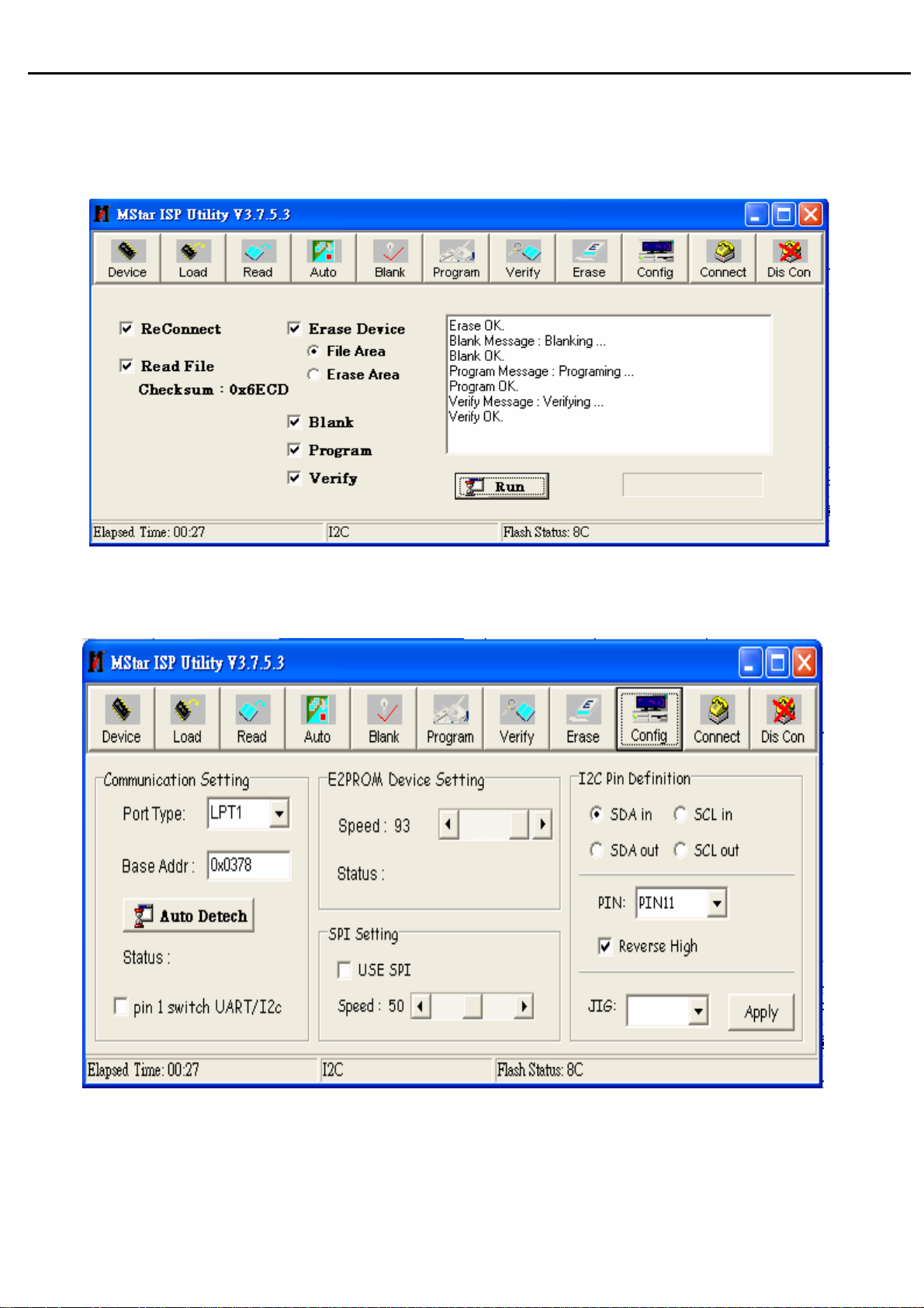
Fourthly, select “AUTO”, and keep its default value. Click “RUN” for beginning programming.
There will be prompting if programming is OK
Note: if programming fails or success rate is not high, click “Config” and adjust its speed in
“E2PROM DEVICE SETTING”
15
Page 17
Acer Acer –LCD-BV203H
g
prog
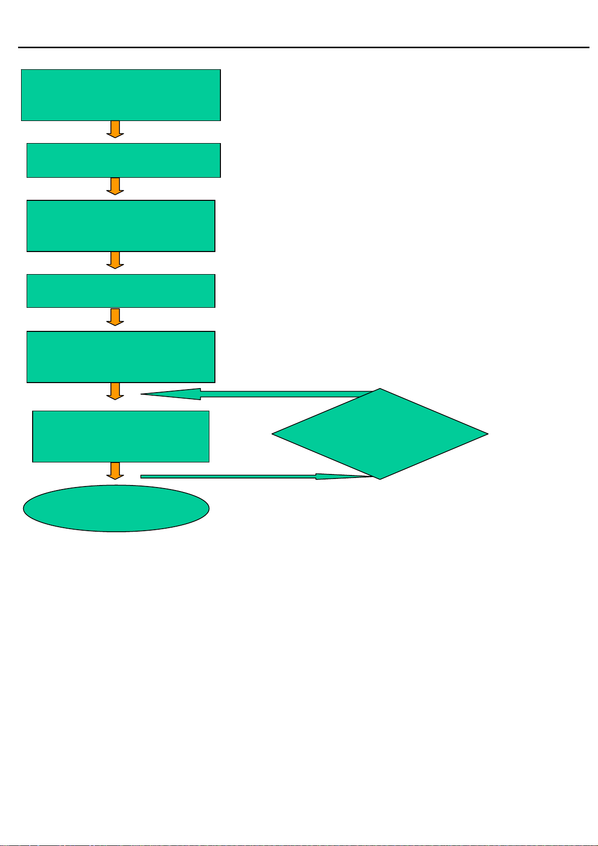
After connecting, AC ON,
DC ON
OK
Open ISP program
OK
Choose manufacturer
and model of FW IC
OK
LOAD FW software
OK
Click Connect and enter
ISP MODE
OK
◆Flowin
chart
Click AUTO and RUN for
beginning programming
OK
Turn off power if
ramming is OK
7. BV203HQ EDID SOP
1、 Software
a.port95nt.exe
b.Edidtool.exe
c.X203H model
2、Hardware
a.PC(winXP or win2000)1PCS;
NG
Choose Config
and adjust
programming
b.Tool(EDID Card、VGA cable & DVI cable)
16
Page 18
Acer Acer –LCD-BV203H
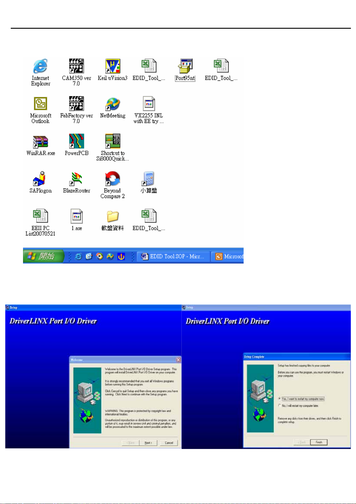
3. .First set up Port95nt.exe
4 . Click next button continually then can finish setting.
17
Page 19
Acer Acer –LCD-BV203H
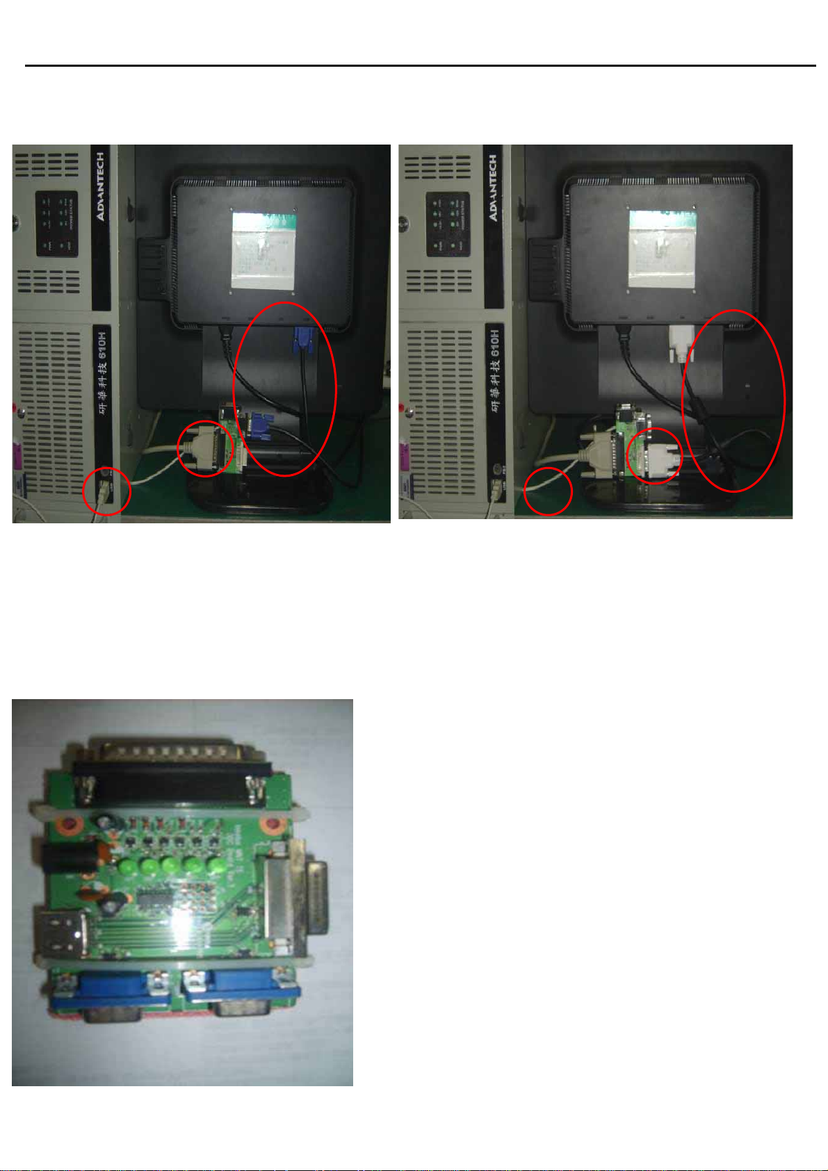
5. EDID Tool Set up
C
C
B
A
A : USB interface provide +5V DC power(No Power is ok )
B : Connect DDC Card and PC with collateral interface ;
C :VGA、DVI use different cable to link DDC and PC
6.
EDID ISP Card:
A
A:Collateral printing interface
(connect with PC)
B:VGA interface (one VGA connect
with PC to provide signal for monitor
B
the other one connect with PC VGA
interface to write VGA EDID, Write
EDID can without providing signal)
C : DVI interface (connect with PC)
D : HDMI Interface
E : Connect DC power+5V
18
Page 20
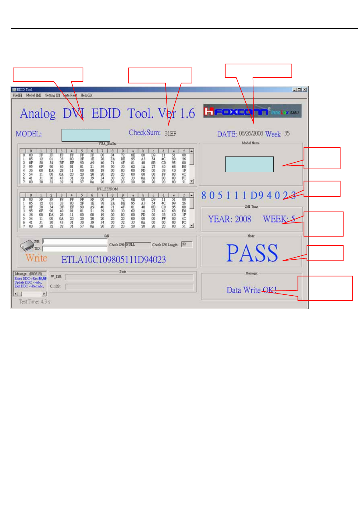
Acer Acer –LCD-BV203H
7.
Writing EDID process :
Model name
BV203HQ
CheckSum
System time
BV203HQ
Model
name
SN
MFG
week
Result
State
information
19
Page 21
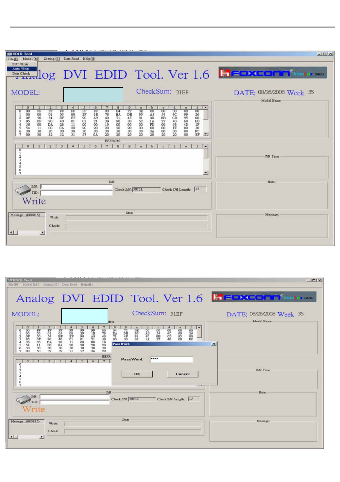
Acer Acer –LCD-BV203H
7.1 Choose File menu in main menu ,choose Auto W rite button,click S/N blank .
BV203HQ
7.2 Cloose the Model in main menu, and the password is 1234.
BV203HQ
20
Page 22
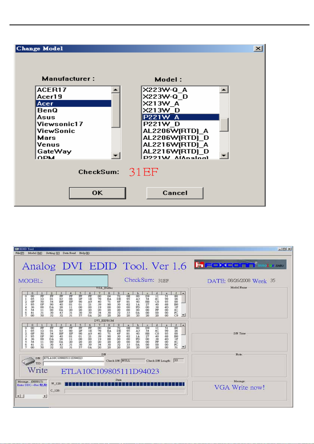
Acer Acer –LCD-BV203H
7.3.Choose the model, such as Acer,
7.4 Input S/N in the Blank, Eg:ETL7777777777777777777,the program can
write directly
BV203HQ
21
Page 23
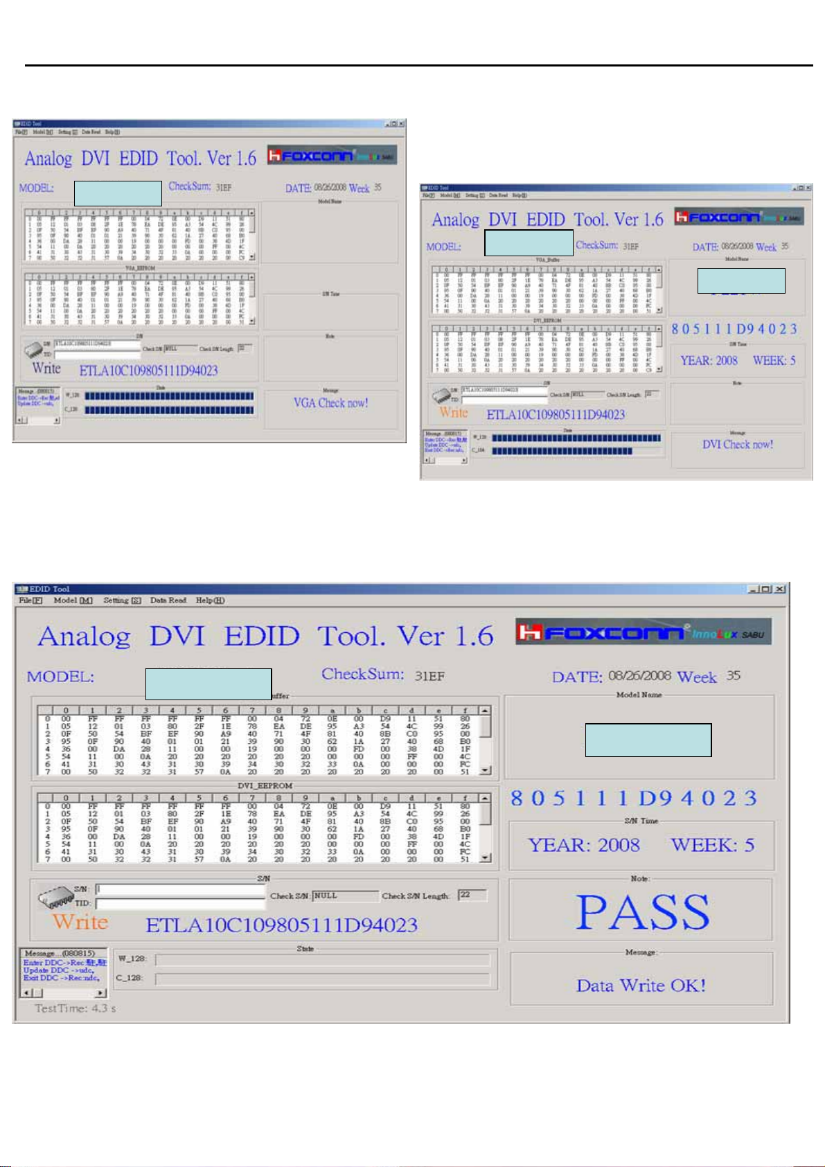
Acer Acer –LCD-BV203H
7.5 The program can CHECK VGA&DVI by itself after writing EDID
BV203HQ
BV203HQ
BV203HQ
7.6 If write successfully , you can see PASS in the right.
BV203HQ
22
Page 24
Acer Acer –LCD-BV203H
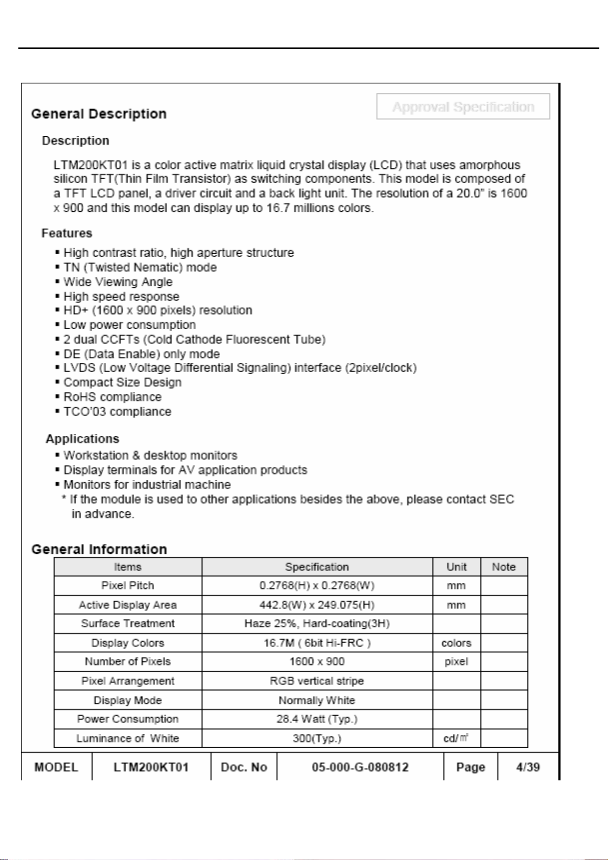
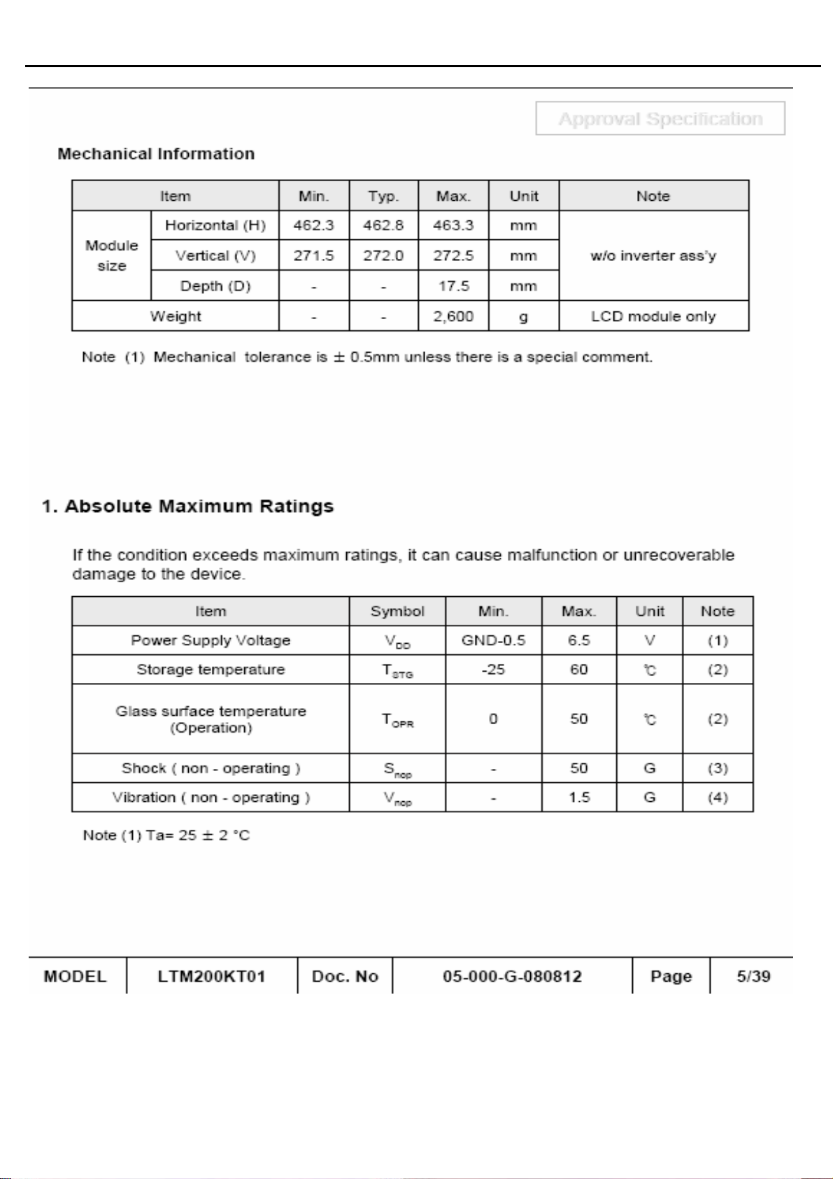
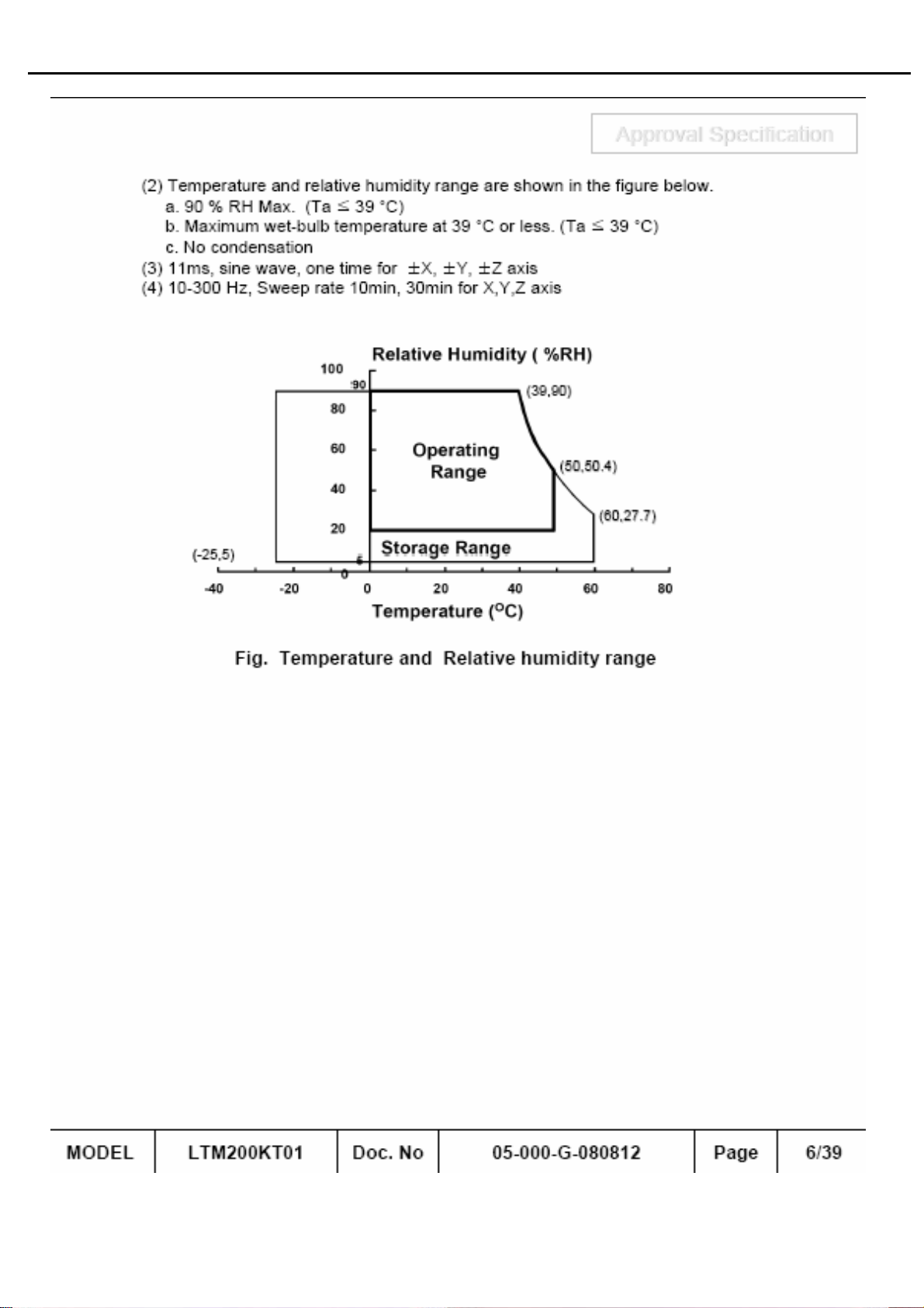
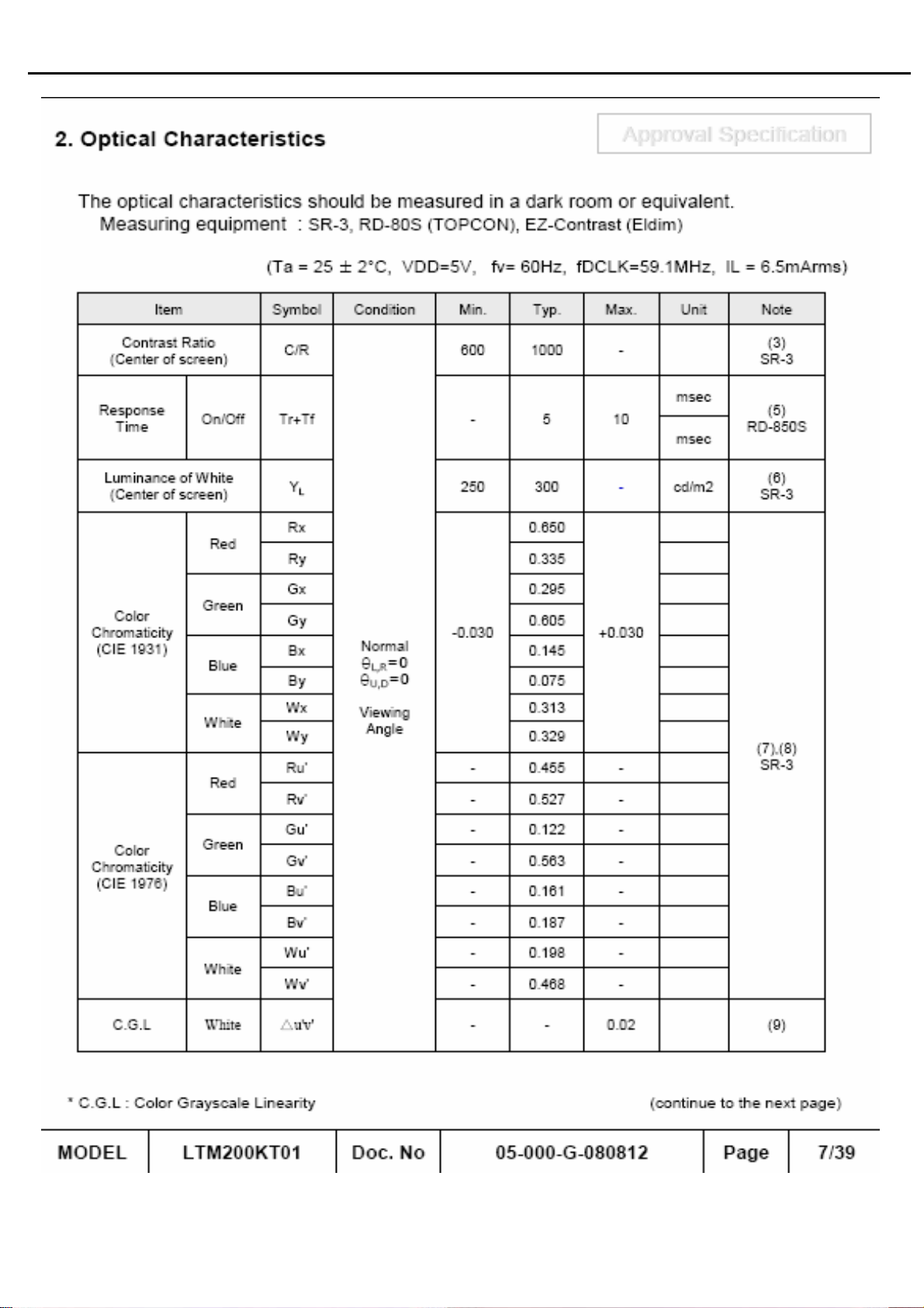
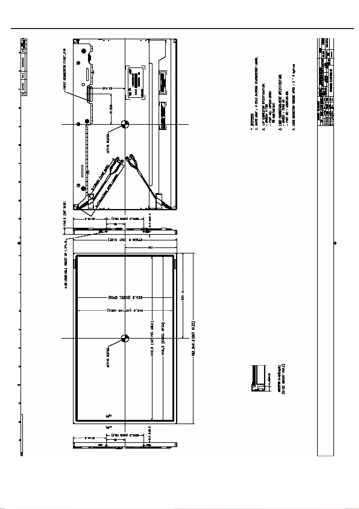
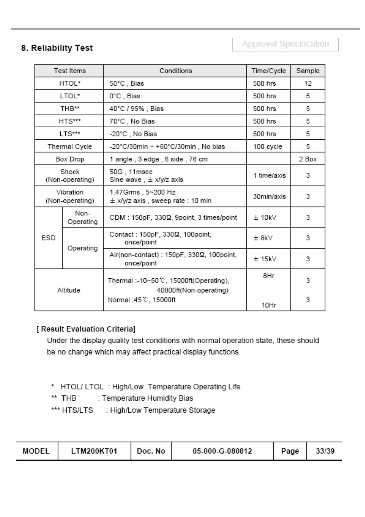
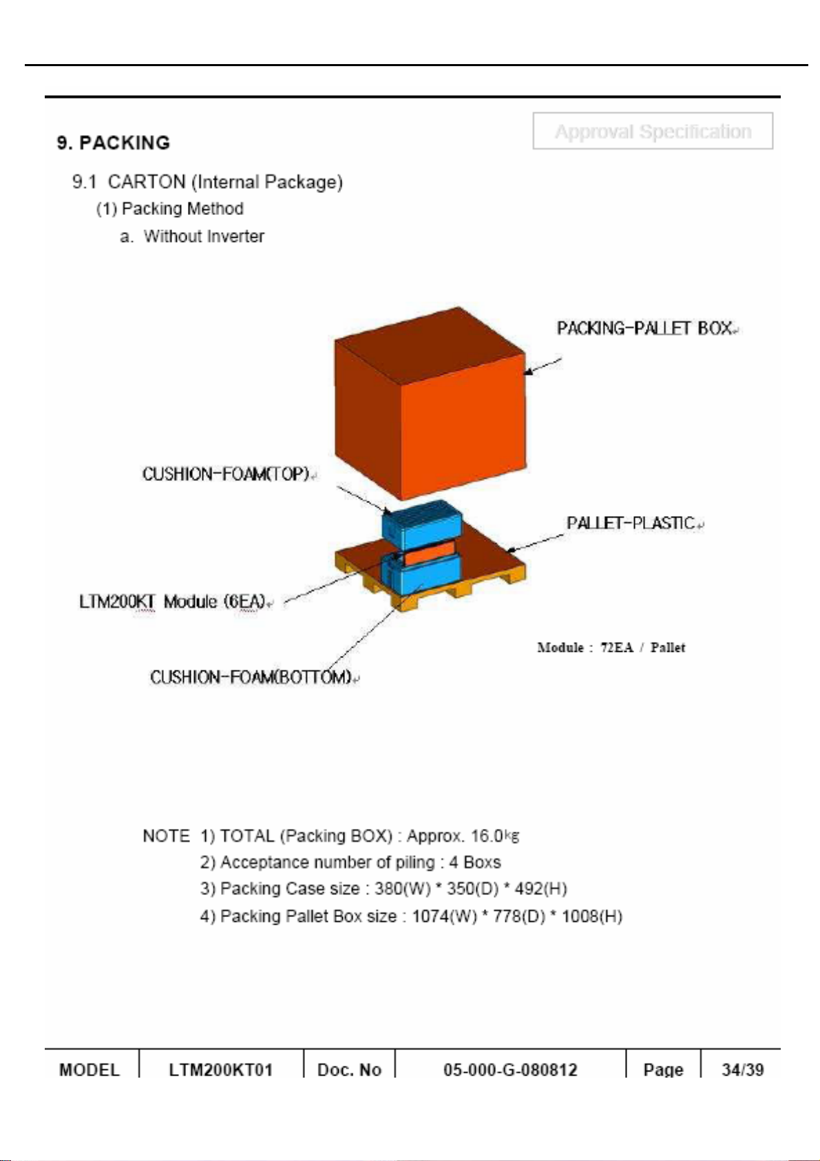
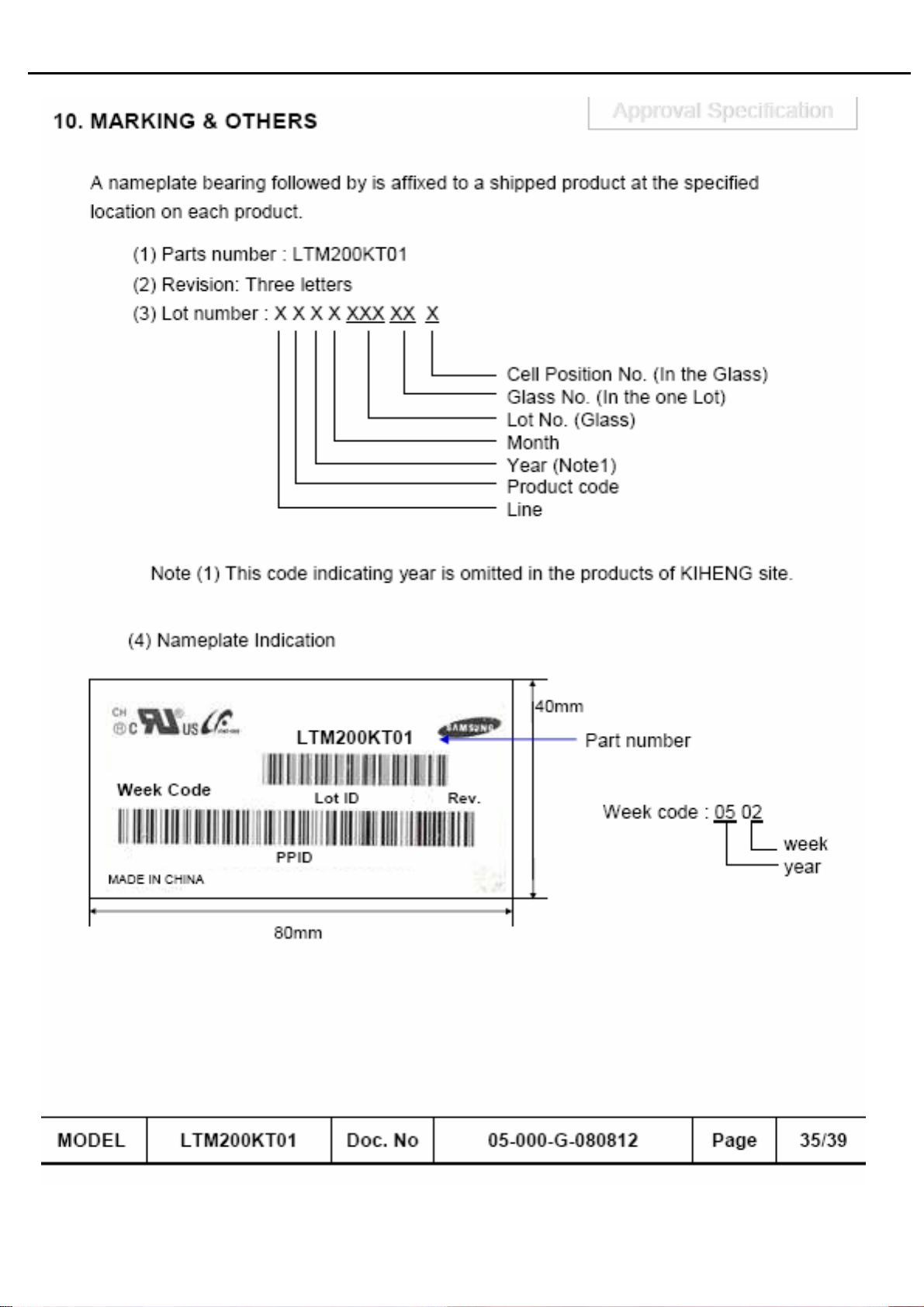
02. Flat Panel Specification
23
Page 25
Acer Acer –LCD-BV203H
24
Page 26
Acer Acer –LCD-BV203H
25
Page 27
Acer Acer –LCD-BV203H
26
Page 28
Acer Acer –LCD-BV203H
27
Page 29
Acer Acer –LCD-BV203H
28
Page 30
Acer Acer –LCD-BV203H
29
Page 31
Acer Acer –LCD-BV203H
30
Page 32
Acer Acer –LCD-BV203H
31
Page 33
Acer Acer –LCD-BV203H
32
Page 34
Acer Acer –LCD-BV203H
33
Page 35
Acer Acer –LCD-BV203H
34
Page 36
Acer Acer –LCD-BV203H
35
Page 37
Acer Acer –LCD-BV203H
36
Page 38
Acer Acer –LCD-BV203H
37
Page 39
Acer Acer –LCD-BV203H
38
Page 40
Acer Acer –LCD-BV203H
39
Page 41
Acer Acer –LCD-BV203H
40
Page 42
Acer Acer –LCD-BV203H
41
Page 43
Acer Acer –LCD-BV203H
42
Page 44
Acer Acer –LCD-BV203H
43
Page 45
Acer Acer –LCD-BV203H
44
Page 46
Acer Acer –LCD-BV203H
45
Page 47
Acer Acer –LCD-BV203H
46
Page 48
Acer Acer –LCD-BV203H
47
Page 49
Acer Acer –LCD-BV203H
48
Page 50
Acer Acer –LCD-BV203H
49
Page 51
Acer Acer –LCD-BV203H
50
Page 52
Acer Acer –LCD-BV203H
51
Page 53
Acer Acer –LCD-BV203H
52
Page 54
Acer Acer –LCD-BV203H
53
Page 55
Acer Acer –LCD-BV203H
54
Page 56
Acer Acer –LCD-BV203H
55
Page 57
Acer Acer –LCD-BV203H
56
Page 58
Acer Acer –LCD-BV203H
57
Page 59
Acer Acer –LCD-BV203H
58
Page 60
Acer Acer –LCD-BV203H
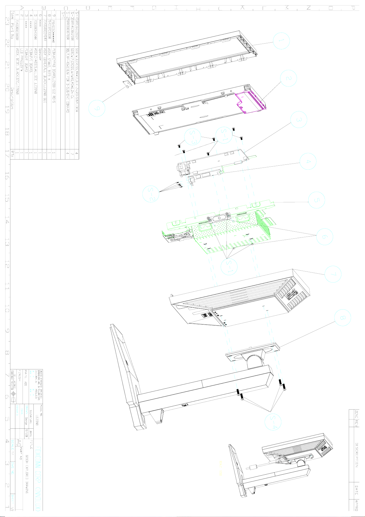
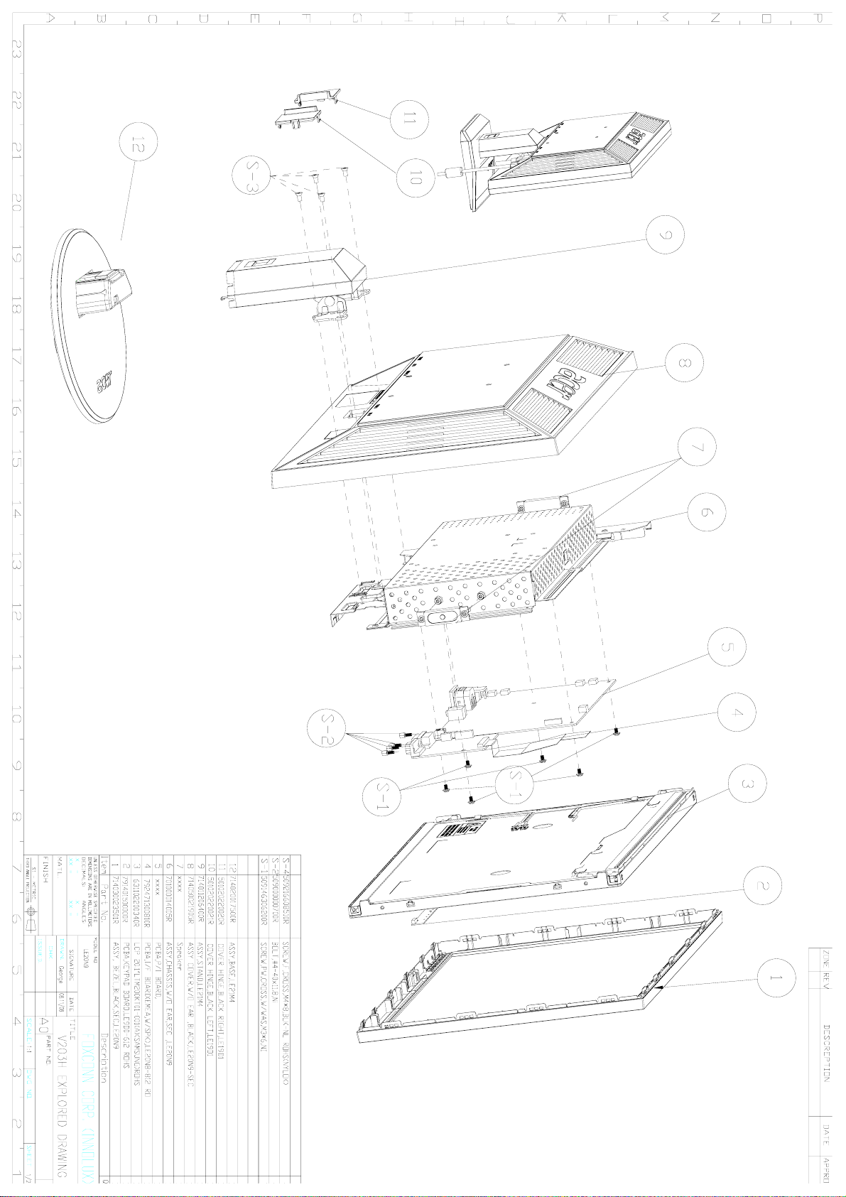
03 Exploded Diagram
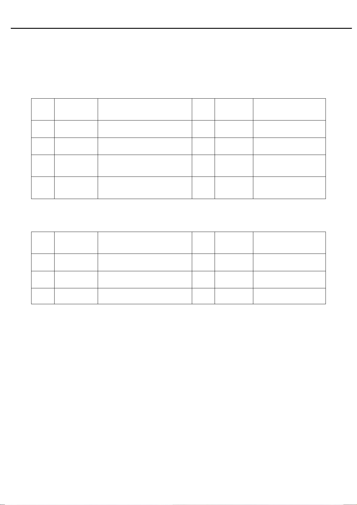
3.1 Screw List
LE20N9Screw List
Item Part No. Description Qty Fixed
T(kg*cm)
1
509146306200R
SCREW,P,CROSS,W/WAS,M3*6,Zn-Cc
7
6.5±0.5
Remark
I/F Board to Chassis*1
Power Board to Chassis*6
2
509000000700R BOLT,#4-40x11.8,Ni ROHS 4
3
509412610500R SCREW,B,CROSS,B.T-4*10,BLK,
ROHS
509216608110R SCREW,F,CROSS,M4*8,Zn,ROHS(NYL
4
OK,35F)
LE20N8 Screw List
Item Part No. Description Qty Fixed
509146306200R
1
2
509000000700R BOLT,#4-40x11.8,Ni ROHS 4
3
509116612102R
3.2 .LCD Exploded drawing
SCREW,P,CROSS,W/WAS,M3*6,Zn-Cc
SCREW,B,CROSS,M4*12,BLK-Zn,ROH
S(NYLOK)#
3.75±0.25
2
4
10±0.5
12±0.5
D-SUB CON*2
DVI CON*2
Hinge to Stand
Hinge to backcover
Remark
T(kg*cm)
7
4
6.5±0.5
3.75±0.25
12±0.5
I/F Board to Chassis*1
Power Board to Chassis*6
D-SUB CON*2
DVI CON*2
Hinge to backcover
59
Page 61
Page 62
Page 63
Acer Acer –LCD-BV203H
04 Troubleshooting
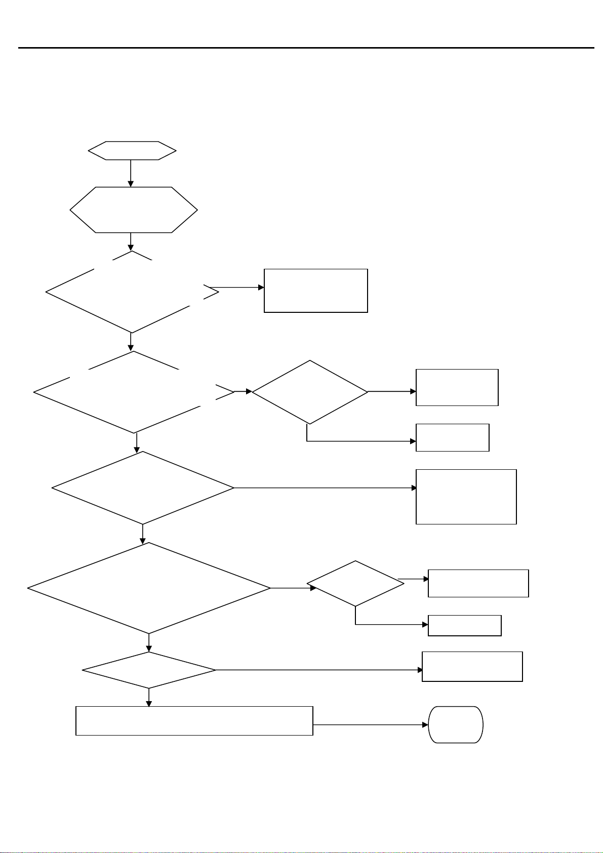
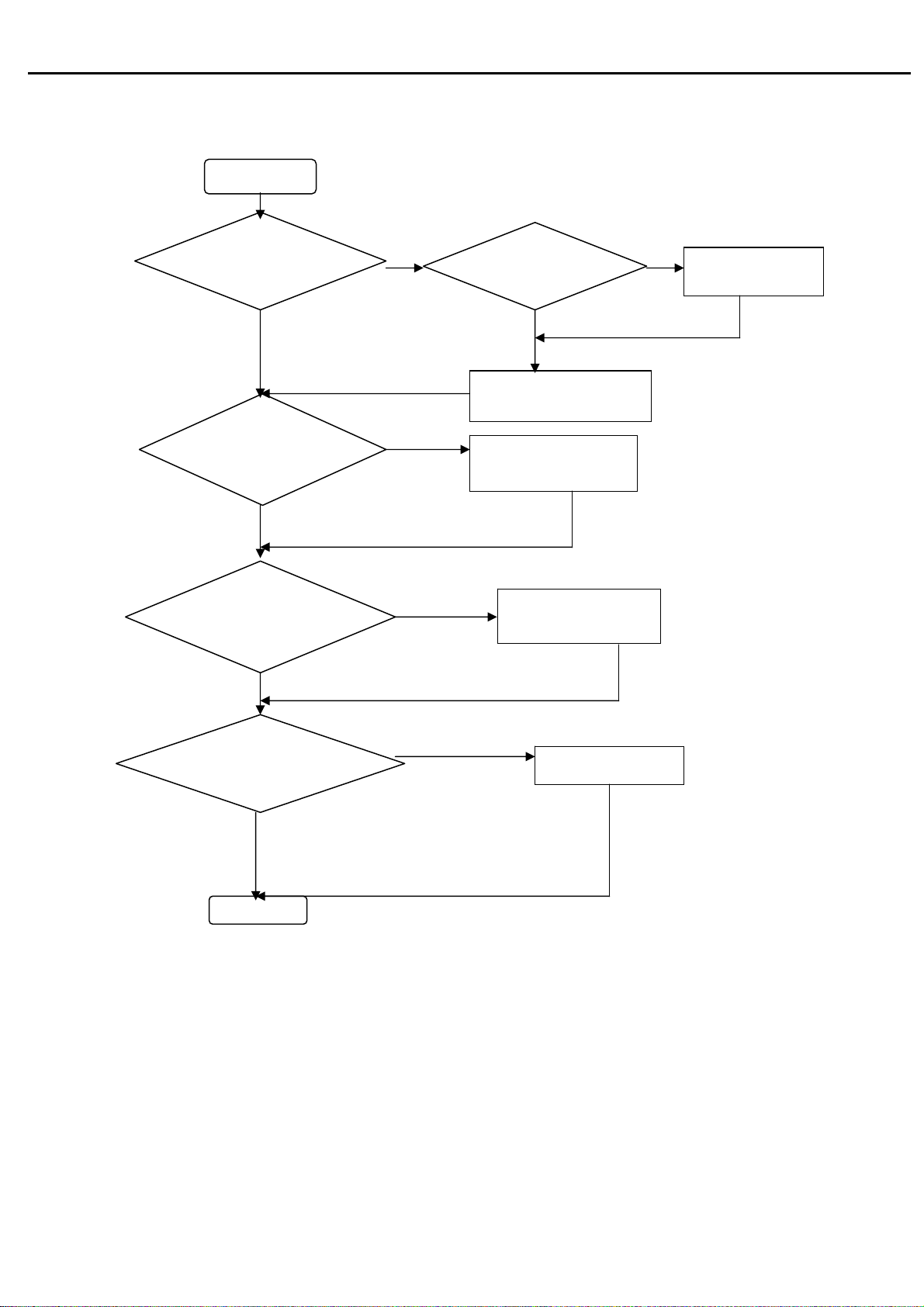
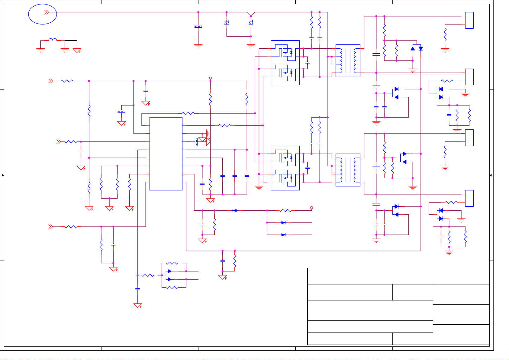
4.1 Inverter circuit on power board
Backlight can’t
be turned on.
Is there 5Vdc
voltage on pin1 of
Is there high-level voltage
on pin8 of IC501?
Are connected rightly
CN501, CN502, CN503 and
CN504?
Is there instantaneously pulse wave
on pin1, pin3, pin15 of IC501 at the
moment of restart?
Check feedback circuit
Check F803 and
power supply
Is Ok IC501?
60
Check I/F
board
R501 open
Connecting the
output connector
again
U501, U502 fail
No
IC501 fail
T501, T502 fail
Page 64
Acer Acer –LCD-BV203H
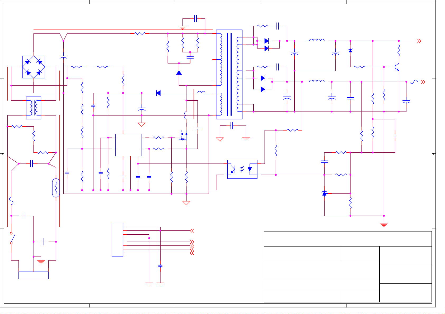
4.2 power board
No power
Check primary
rectifier voltage
Check pin1 of
IC802 voltage
Check pin7 of
IC802 voltage
Check Q804 Ds
have triangle pulse
Check circuit
if short
Check F801, P801,
D801, R805
Check R809 R810,
R811, R812
Check R806, R807,
R808, D804
Check IC802,Q804
61
Check IC802,
C805, T801,
Page 65
Acer Acer –LCD-BV203H
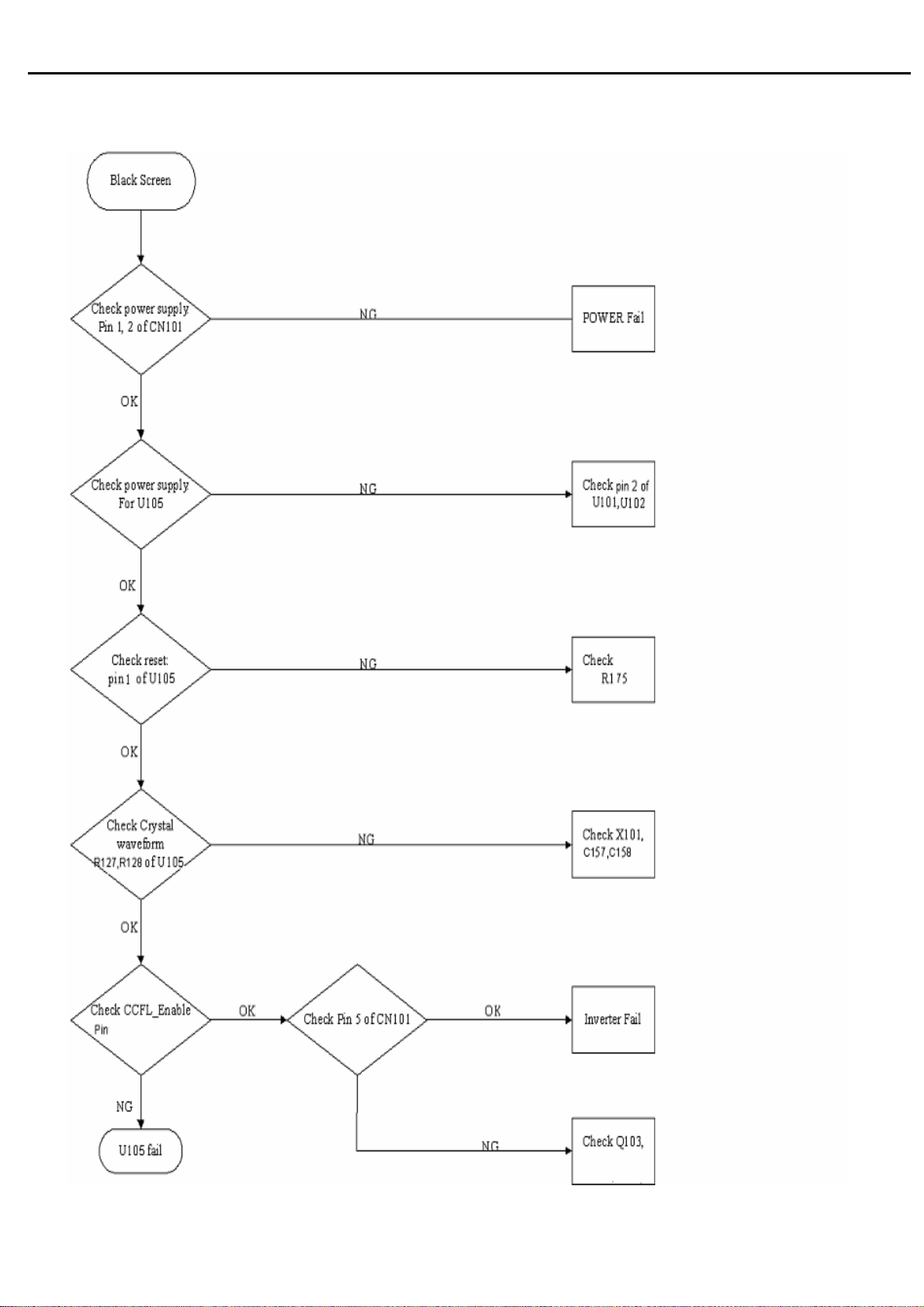
4.3 Black Screen
62
Page 66
Acer Acer –LCD-BV203H
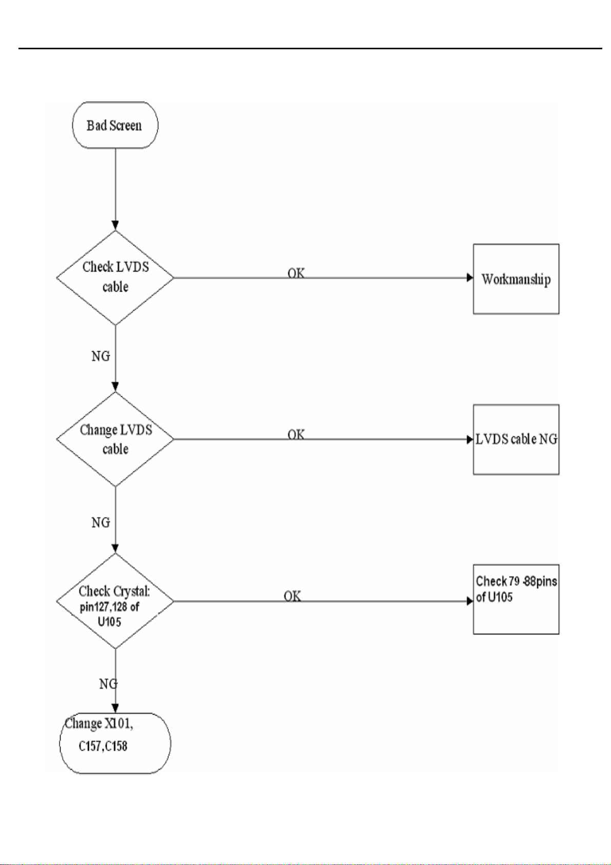
4.4 Bad Screen
63
Page 67
Acer Acer –LCD-BV203H
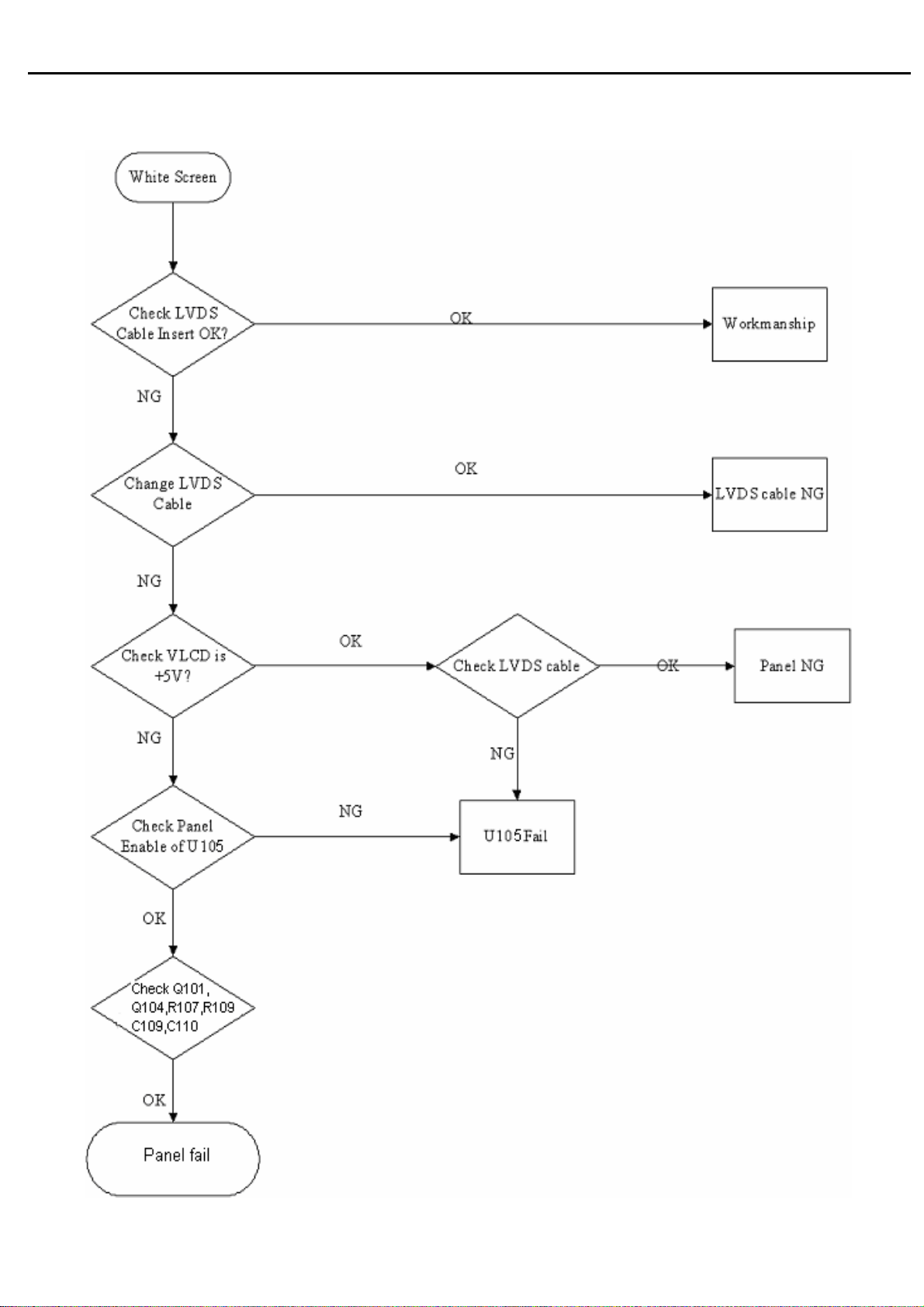
4.5 White Screen
64
Page 68
Acer Acer –LCD-BV203H
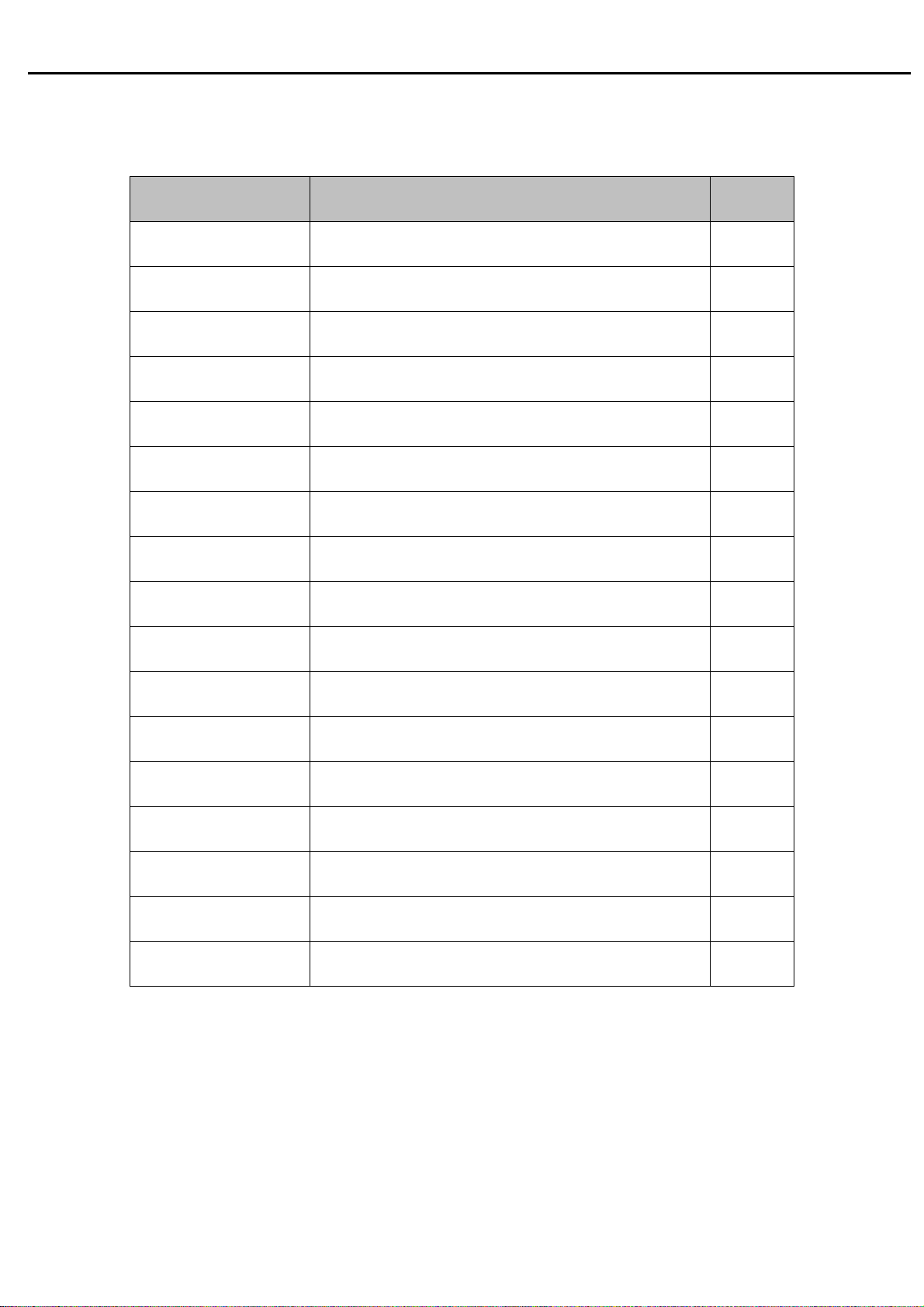
05 Spare parts List
Acer P/N : ET.LFF07.005 ODM PN Description MOQ
792471300811R PCBA,I/F BOARD(EMEA,W/O),LE20N8-812 ROHS
792291400810R PCBA,P/I BOARD,W/O SPK,LE20M2-812 ROHS
791401500000R PCBA,KEYPAD BOARD,LE9D0-612 ROHS
714050021903R ASSY COVER,W/O SPK ,BLACK,LE20N9-SEC
714030023501R ASSY, BEZEL,BLACK,SEC,LE20N9
714011206400R ASSY,STAND,LE21M4
714020017500R ASSY,BASE,LE21M4
501020220020R COVER HINGE,BLACK RIGHT,LE19D1
501020220021R COVER HINGE,BLACK LEFT,LE19D1
453070800240R PWRCORD 10A /250V BLK 6FT SWISS H05VV-F
453010100380R CABLE,D-SUB 15P MALE 6FT BLACK/BLUE, ROH
50
50
50
50
50
50
50
50
50
50
50
453030300370R CABLE,DVI-D 18+1P MALE 6FT BLACK , ROHS
50
50
430300801800R HRN ASSY 2x4P 75mm UL1571#28,ROHS
50
430300801680R HRN ASSY 2x4P to 8P 200mm UL1571#28,ROHS
50
430303001500R HRN LVDS FFC 30P 182mm ROHS
50
701000014003R ASSY,CHASSIS,W/O SPK,SEC ,LE20N9
50
631102200450RA LCP 20.0"LTM200KT01-A02(A)(SAMSUNG)ROHS
65
Page 69
Acer Acer –LCD-BV203H
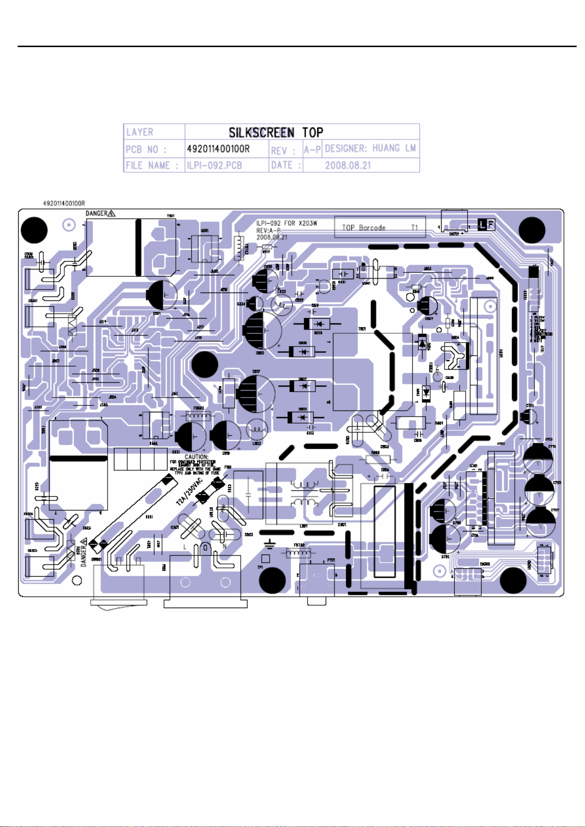
06 Schematics and Layouts
6.1 PI BD Layout
66
Page 70
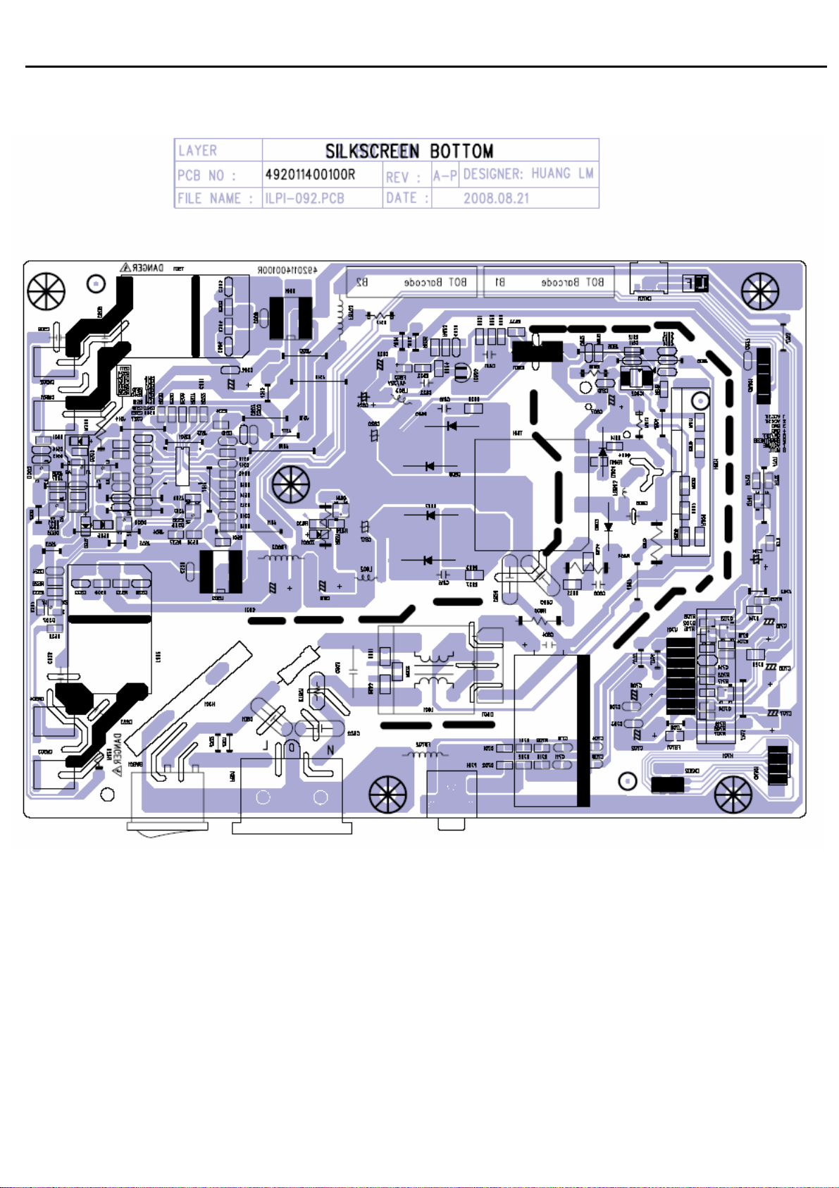
Acer Acer –LCD-BV203H
6.2 PI BD Layout
67
Page 71
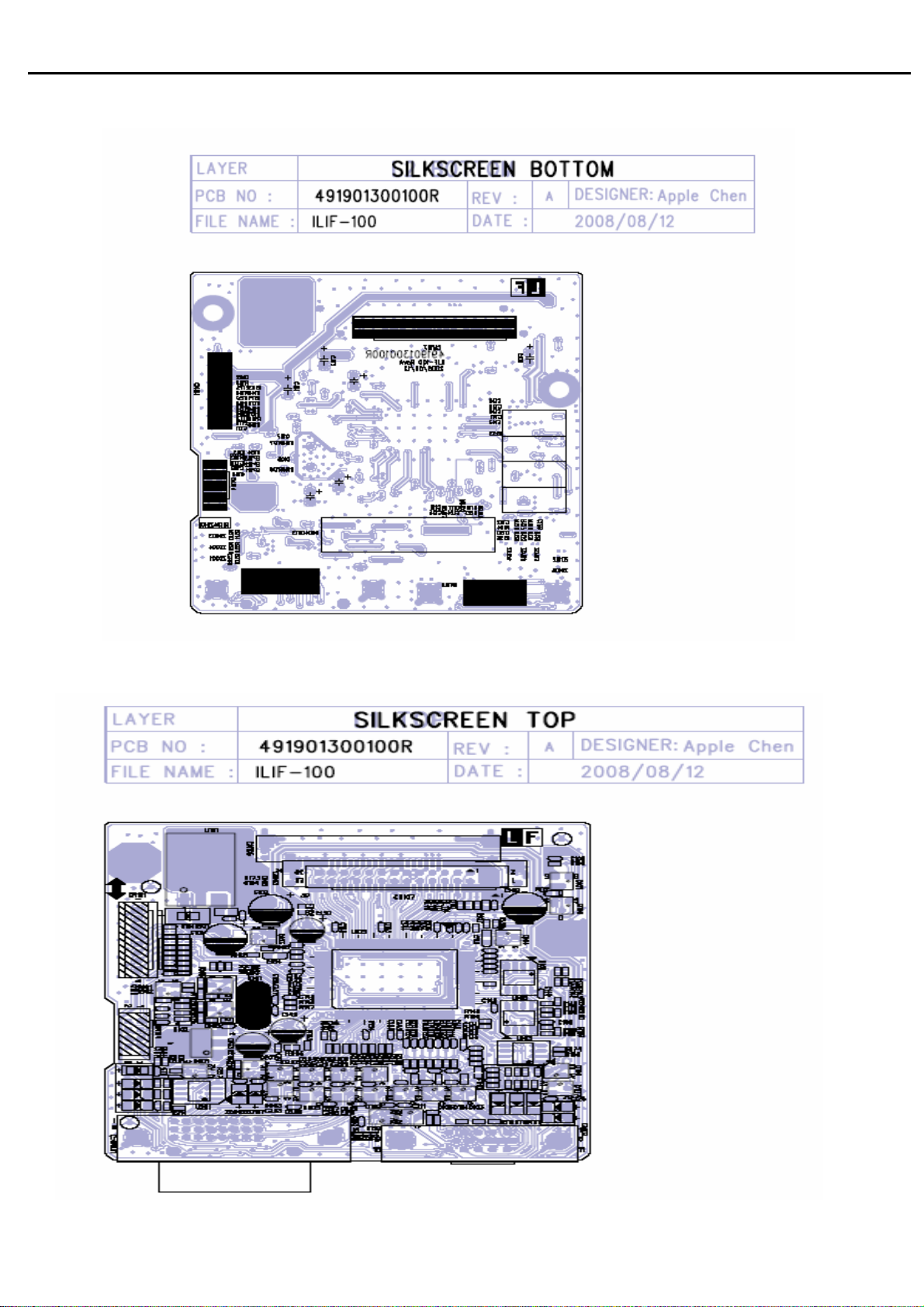
Acer Acer –LCD-BV203H
6.3 IF BD Layout
6.4 IF BD Layout
68
Page 72
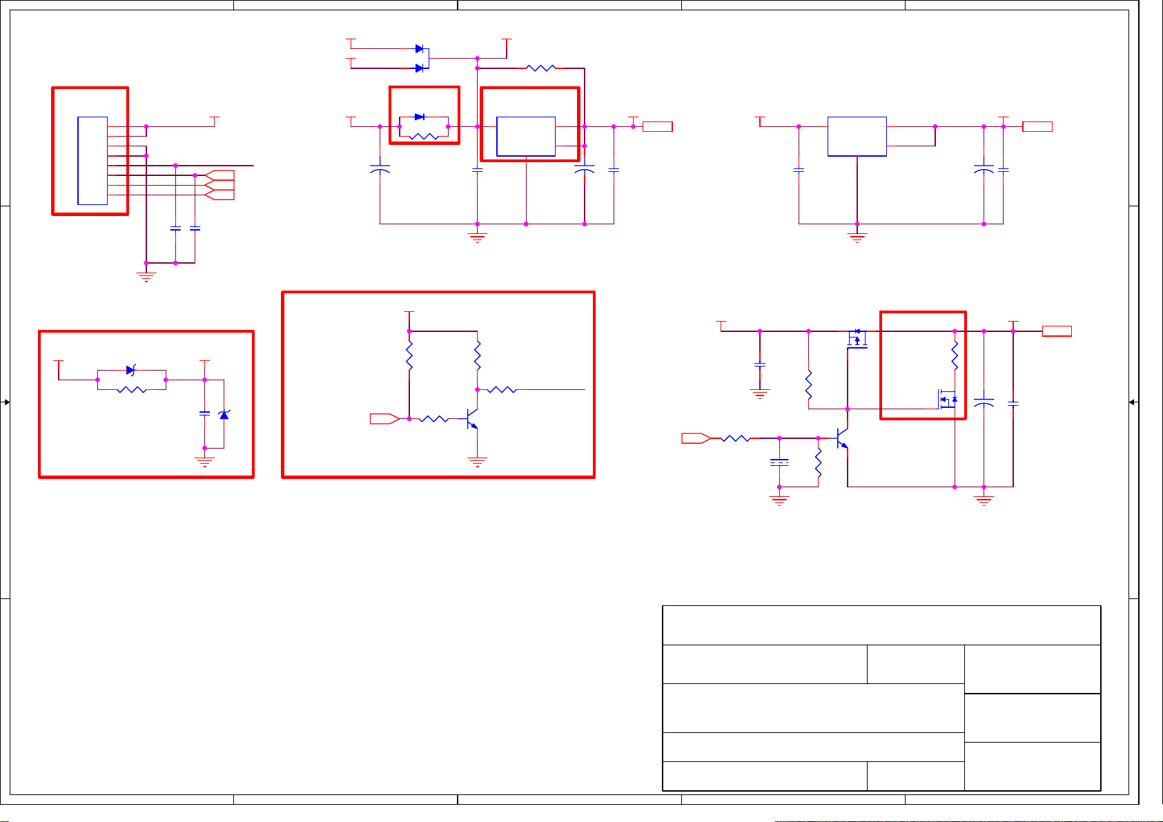
5
4
3
2
1
D107
BAT750-LF/NC
DVI5V
Note 1
D D
CN101
8P 2.0mm
1
2
3
4
5
6
7
8
CON--JWT-A2008WV08P-1
VCC5V
CCFL_ON/OFF
BRIGHTNESS 6
VOLUME 6
MUTE 6
C101
100u/16V
1
2
Note 2
D101
SSM24APT/NC
DIO--SMA
R101
0
+
R0805
3
C104
0.1/16V
VCC4.5VVGA5V
Note 3
U101
AP1084K33LA
3
VIN
R173 0/NC
R0805
2
VOUT
4
PAD
ADJ
1
C102
100u/16V
U102
LD1117AL-1.8V
3
+3.3V 6
+
C105
0.1/16V
C106
0.1/16V
VIN
VOUT
PAD
ADJ
1
2
4
C103
22u/16V
+1.8VVCC5V +3.3V+3.3V
+1.8V 6
+
C107
0.1/16V
To Power/Inverter
Board
C C
Note 4
VCC5V VCC_ESD
ZD101
6V2/NC
R113
0
R0805
GND
C162 0.1/16V
C111
0.1/16V
C175 0.1/16V
GND
ZD107 6V2/NC
Note 5
+3.3V
R102
10K
CCFL_ENABLE6
R106
100K
GND GND
R103
1
10K
32
PMBT3904
GND
R105
4K7
Q103
CCFL_ON/OFF
PANEL_ENABLE6
C108
0.1/16V
R107
100K
GND
C112
1u/16V
R109
100K
R108
47K
Q101
AP2305GN
1
1
32
Q104
PMBT3904
Note 6
32
R112
51/NC
R0603
1
Q102
2N7002/NC
VLCDVCC5V
VLCD 6
32
+
C110 0.1/16V
C109 100u/16V
B B
GNDGND
Note:
1. CN101 is no locked packgae for normal model.CN101 is locked packgae for special model(Dell).
2. D101 must be co-layed with R101
3. U101 must contain TO263, TO252 and SOT223 package
4. ZD101 must be co-layed with R113. ZD101 is used for ESD back drive.Reserved C111 for EMI issue.
5. P/I Board High Enable.
Document Number : SIZE :
6. Reserved R111,R112,Q102 for panel power discharge.
A A
TITLE :
DATE :
InnoLux
COMMON
POWER (DC TO DC)
2008-1-30
SHEET OF
5
4
3
2
MSTAR_TSUMU5PEHJ
A4
63
Rev :
V01
APPRO BY :
CHECK BY :
DRAWN BY :
STONE
1
Page 73
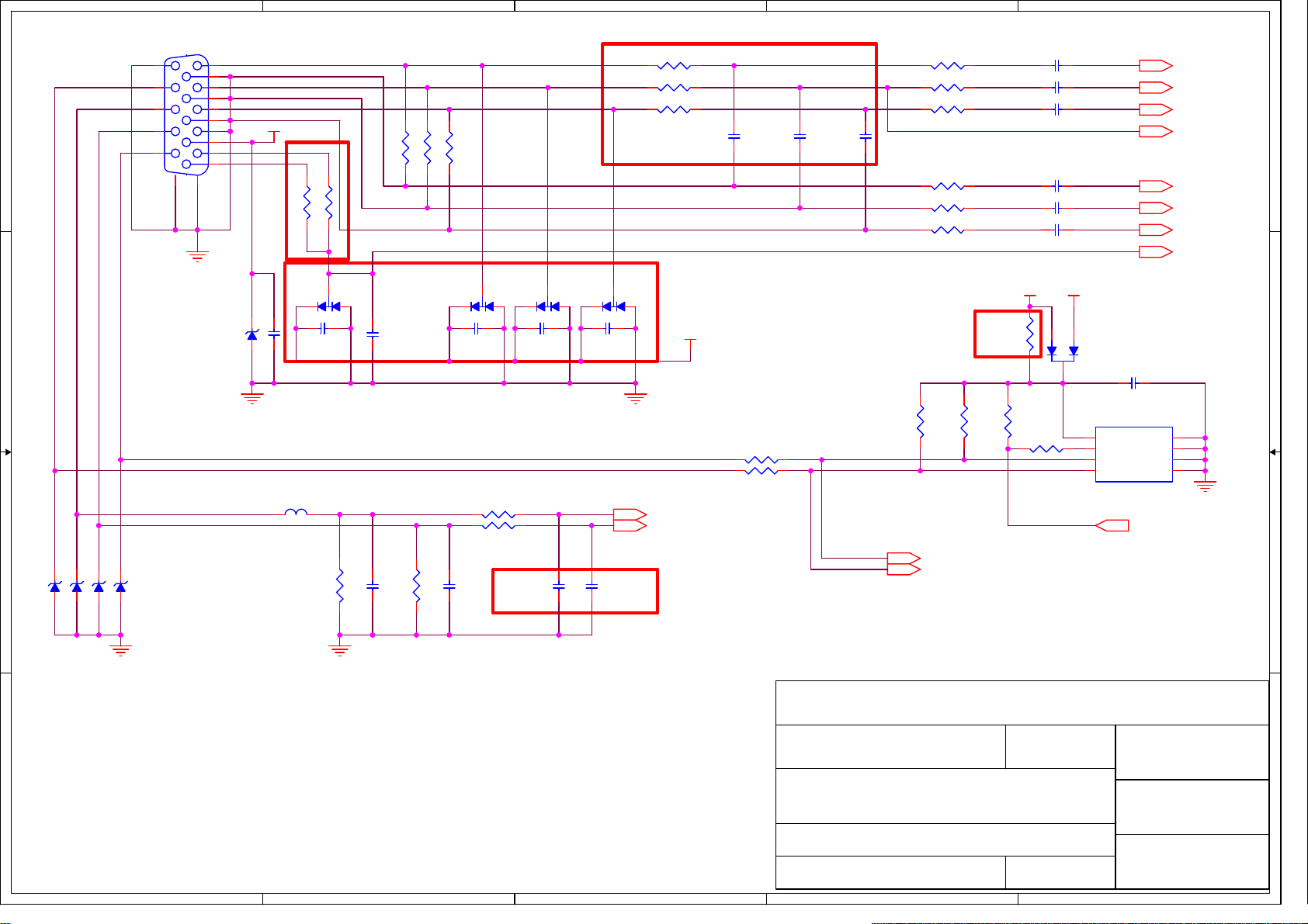
5
4
3
2
1
1
0.1/16V/NC
Note 2
3
2
C125
RB101 0
R0603
RB102 0
R0603
RB103 0
R0603
D105
BAV99
1
VCC_ESD
GND
HSYNC 6
VSYNC 6
C116
10p/50V/NC
C117
10p/50V/NC
R131 100
R132 100
C118
10p/50V/NC
R114 75 1%
R115 75 1%
R116 75 1%
R122 75 1%
R123 75 1%
R124 75 1%
R127
R128
4K7
4K7
Note 4
R129
10K
C113 0.047u/16V
C114 0.047u/16V
C115 0.047u/16V
C119 0.047u/16V
C120 0.047u/16V
C121 0.047u/16V
VGA_DET
VCC5V
R126
0/NC
R130
1K
2
VGA5V
1
3
8
7
6
D106
BAV70
U103
AT24C02BN
VCC
WP
SCL
RED+ 6
GREEN+ 6
BLUE+ 6
SOG 6
RED- 6
GREEN- 6
BLUE- 6
VGA_DET 6
C128
0.1/16V
1
A0
2
A1
3
A2
45
GNDSDA
WP_EDID 5,6
GND
CN102
DZ11AA1-H5W6-4F
11
12
13
D D
C C
14
15
VGA_SCL
VGA_SDA
1
6
2
7
3
8
4
9
5
10
17
16
GND
ZD102 6V2
GND
VGA5V
C126 0.1/16V
R
G
B
Note 1
Note 3
FB101
120Ω
R120 0/NC
R121 0
D102
3
BAV99
2
C122
0.1/16V/NC
75 1%
75 1%
R117
R118 75 1%
R119
VGA_DET
D103
3
BAV99
1
1
C127
0.1/16V
2
C123
0.1/16V/NC
R133 1K
R134 1K
D104
3
BAV99
2
C124
0.1/16V/NC
B B
ZD103 6V2
ZD104 6V2
ZD105 6V2
ZD106 6V2
GND
R135 2K2
GND
C129 33p/50V
R136 2K2
C130 33p/50V
Note:
1. R120 is reserved for Samsung model.
2. R0603 package for Bead. C116,C117,C118 are reserved for EMI or performance issue.
3. C122,C123,C124,C125 are reserved for ESD or EMI issue.
Note 5
C131
33p/50V/NC
C132
33p/50V/NC
InnoLux
Document Number : SIZE :
4. R126 is reserved for Samsung model.
A A
5. C131,C132 are reserved for tuning performance issue.
TITLE :
DATE :
SHEET OF
5
4
3
DDC_SCL_VGA 6
DDC_SDA_VGA 6
VGA-INPUT
2008-1-30
2
MSTAR_TSUMU5PEHJ
A4COMMON
STONE
64
Rev :
V01
APPRO BY :
CHECK BY :
DRAWN BY :
1
Page 74
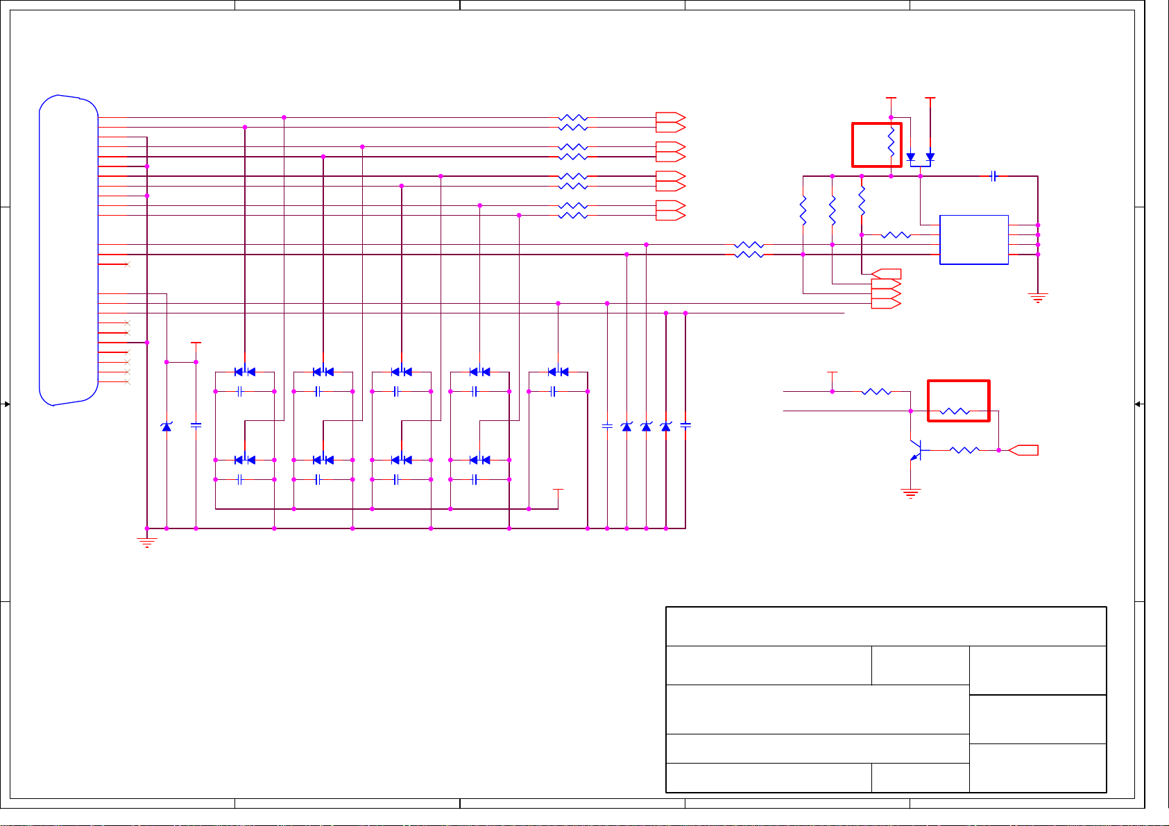
5
CN201
DVI-D_CON
D D
C C
RX2-
RX2+
GND
RX1-
RX1+
GND
RX0-
RX0+
GND
RXC+
RXC-
SCL
SDA
GND
HP
RX4-
RX4+
GND
RX3-
RX3+
RX5-
RX5+
VS
5V
1
2
3
9
10
19
17
18
22
23
24
6
7
8
14
15
16
4
5
11
12
13
20
21
DVI_RX2DVI_RX2+
DVI_RX1DVI_RX1+
DVI_RX0DVI_RX0+
DVI_RXC+
DVI_RXC-
DVI_SCL
DVI_SDA
DVI_DET
HPD_DVI
DVI5V
ZD201 6V2
C202 0.1/16V
2
C203
0.1/16V
2
D202
3
BAV99
D203
3
BAV99
2
1
0.1/16V
2
1
C205
D204
3
BAV99
D205
3
BAV99
4
D206
3
2
C207
0.1/16V
2
BAV99
D207
3
BAV99
1
1
1
1
2
C209
0.1/16V
2
D208
3
BAV99
D209
3
BAV99
1
1
3
R201 10
R202 10
R203 10
R204 10
R205 10
R206 10
R207 10
R208 10
D210
3
BAV99
2
C211
0.1/16V
2
VCC5V
4K7
DVI5V
Note 1
R215
0/NC
R213
10K
R214
1K
R217 10K
Q201
PMBT3904
RX2- 6
RX2+ 6
RX1- 6
RX1+ 6
RX0- 6
RX0+ 6
RXC+ 6
RXC- 6
R209 100
R210 100
1
C212 0.1/16V
ZD203 6V2
ZD204 6V2
ZD202 6V2
C213 0.1/16V
R211
4K7
DVI5V
HPD_DVI
R212
DVI_DET
HPD_DVI
DVI5V
2
1
D201
BAV70
3
U201
AT24C02BN
8
VCC
7
WP
6
SCL
WP_EDID 4,6
DDC_SCL_DVI 6
DDC_SDA_DVI 6
DVI_DET 6
Note 2
R218
100/NC
32
R219
4K7
1
C201
0.1/16V
1
1
A0
2
A1
3
A2
45
GNDSDA
GND
HPD_CTRL 6
C204
B B
GND
0.1/16V
C206
0.1/16V
C208
0.1/16V
C210
0.1/16V
VCC_ESD
InnoLux
MSTAR_TSUM5PEHJ
HDCP Function
GND
Note:
1. R215 is reserved for Samsung model.
2. R218 is reserved for some model.
A A
5
4
3
Document Number : SIZE :
TITLE :
DVI-INPUT
DATE :
SHEET OF
2008-1-30
65
2
Rev :
A4COMMON
V01
APPRO BY :
CHECK BY :
DRAWN BY :
STONE
1
Page 75
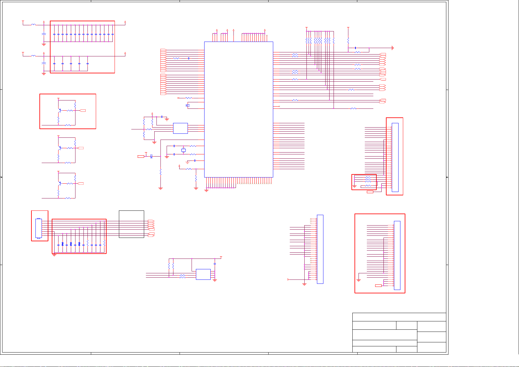
5
VDDP_33
C150
22u/16V
C142
22u/16V
Note4
CN104
2x4P 2.0mm
CON--CLX-CI0108P1VDL-1
To Keypad
Board
VDDC_18
Note 2
+
GND
+
GND
PMBT3906/NC
LED_B
LED_A
LED_G
1
2
3
4
5
6
7
8
Note 1
Q106
R163
330/NC
R0603
Q107
PMBT3906
R165
330
R0603
Q108
PMBT3906
R168
330
R0603
Note 3
GND
C154 0.1/16V
C159 0.1/16V
C134 0.1/16V
C135 0.1/16V
C133 0.1/16V
C143
0.1/16V
VCC5V
VCC5V
VCC5V
C155 0.1/16V
C156 0.1/16V
C144
0.1/16V
2
1
R162
3
10K/NC
R164
0R0603
2
1
R166
3
10K
R167
2
1
R169
3
10K
R170
100/NC
R0603
C167 0.1/16V
C168 0.1/16V
EP101 5P35V/NC
C136 0.1/16V
C160 0.1/16V
C145
0.1/16V
100/NCR0603
EP102 5P35V/NC
C137 0.1/16V
C146
C147
0.1/16V
0.1/16V
R161
10K
LED_B_C
R177
10K
LED_A_C
R176
10K
LED_G_C
C170 0.1/16V
C169 0.1/16V
R193 0/NC
C171 0.1/16V
EP103 5P35V/NC
C138 0.1/16V
C172 0.1/16V
C149 0.1/16V
C139 0.1/16V
PLUS-MINUS
R194 0/NC
C173 0.1/16V
C141 0.1/16V
C161 0.1/16V
+3.3V
FB102
60Ω
D D
C C
B B
+1.8V
FB105
60Ω
4
AVDD_33
AVDD_18
R189
10K/NC
WP_FW
R192
10K
VCC4.5V
3
Define for X203H
MENU
RIGHT/LEFT
AUTO
E-color
LED_A
LED_G
POWER
DDC_SDA_VGA4
DDC_SCL_VGA4
DDC_SDA_DVI5
DDC_SCL_DVI5
R190
10K
VCC4.5V
C164 1u/16V
SCL_OSD
SDA_OSD
3
AVDD_33
VDDC_18
AVDD_18
8
104
14
53
74
126
20
21
VDDC
VDDC
VDDC
GND
172952
AVDD_33
AVDD_33
AVDD_33
GND
GND
GND
GND
GND
7288101
+3.3V
1
2
3
45
GND
VDDC
AVDD_18
GPIO_P22/PWM1/GPIO_P23/PWM1
GPIO_P24/PWM2/GPIO_P27/PWM2
GPIO_P13/PWM2/GPIO_P26/PWM2
TSUMU58EHJ-LF-1
LVA4M/GPO[6]
LVA4P/GPO[7]
GND
GND
GND
GND
GND
GND
GND
76
75
113565557616470
106
105
686963
62
C152 0.047u/16V
390 1%
C148
1u/16V
SDO
2
SO
SCZ
1
CS#
SCK
6
SCK
SDI
R147 0
R148 0
C153 0.1/16V
R180 10K
U106
8
VCC
7
WP
6
SCL
AT24C16AN
28
RIN0P
27
RIN0M
25
GIN0P
24
GIN0M
26
SOGIN0
23
BIN0P
22
BIN0M
32
HSYNC0
33
VSYNC0
34
DDCA_SDA/RS232_TX
35
DDCA_SCL/RS232_RX
9
RX2P
10
RX2N
12
RX1P
13
RX1N
15
RX0P
16
RX0N
18
RXCKP
19
RXCKN
5
DDCD_SDA
6
DDCD_SCL
7
REXT
31
REFP
30
REFM
41
SDO
42
CSZ
43
SCK
44
SDI
108
RST
128
XIN
127
XOUT
102
BYPASS
37
MODE
GND
GND
1
11
GND
C140
0.1/16V
A0
A1
A2
GNDSDA
RED+4
RED-4
GREEN+4
GREEN-4
R159 470
SOG4
BLUE+4
BLUE-4
HSYNC4
VSYNC4
RX2+5
RX2-5
RX1+5
RX1-5
Rx0+5
RX0-5
RXC+5
RXC-5
AVDD_33
R144
+3.3V
C165
0.1/16V
GND
U108
8
VCC
7
HOLD#
3
WP#
4 5
R175 100K
R138
4K7
GND SI
PM25LV010A-100SCE
C157 22p/50V
X101
14.31818MHz
C158 22p/50V
VDDP_33
R137
4K7
WP_OSD
R142 100
R143 100
R149 10K/NC
R191
1K
GND
KEY1
ADC_KEY1
ADC_KEY2
LED_B
LED_A
LED_G
KEY2
VDDP_33
87
112
107
40
59
114
606566
54
58
VDDP
VDDP
GPIO_P00/SAR0/GPIO_P17/SAR0
GPIO_P01/SAR1/GPIO_P00/SAR1
GPIO_P02/SAR2/GPIO_P01/SAR2
GPIO_P03/SAR3/GPIO_P02/SAR3
LVB4M/NC
LVB4P/NC
90
89
71
VDDP
VDDP
VDDP
VDDP
VDDP
VDDP
VDDP
VDDP
VDDP
GPIO_P06
GPIO_P07
GPIO_P14/PWM0
GPIO_P15
GPIO_P16
GPIO_P44/GPIO_P41
GPIO42/GPIO_P24
GPIO_P04/GPIO_P03/PWM3
GPIO_P25/GPIO_P12/PWM3
I2C_MCL/GPIO_P10
I2C_MDA/GPIO_P11
GPIO_P43/GPIO_P42
GPIO_P45/GPIO_P04
GPIO_P46/GPIO_P05
GPIO_P47/GPIO_P22
LVBCKM
LVBCKP
LVACKM
LVACKP
NC/GPIO_P25
NC/GPIO_P43
NC/GPO[2]
NC/GPO[4]
NC/GPO[0]NCNCNCNC
115
111
110
67
VDDP
103
VCTRL
LVB0M
LVB0P
LVB1M
LVB1P
LVB2M
LVB2P
LVB3M
LVB3P
LVA0M
LVA0P
LVA1M
LVA1P
LVA2M
LVA2P
LVA3M
LVA3P
116
VCC5V_DET
119
R154 1K
120
R155 1K
121
122
123
124
2
3
R125 1K
4
R160 1K
36
48
R153 1K
50
51
73
109
125
39
38
R216 1K
49
47
46
45
RXO0-
100
RXO0+
99
RXO1-
98
RXO1+
97
RXO2-
96
RXO2+
95
RXOC-
94
RXOC+
93
RXO3-
92
RXO3+
91
RXE0-
86
RXE0+
85
RXE1-
84
RXE1+
83
RXE2-
82
RXE2+
81
RXEC-
80
RXEC+
79
RXE3-
78
RXE3+
77
NC
NCNCNC
118
117
RXO0RXO0+
RXO1RXO1+
RXO2RXO2+
RXOCRXOC+
RXO3RXO3+
VLCD
FOR SINGLE LVDS INPUT
2
+3.3V
R172 10K
R139 10K/NC
R151
R184 10K
R152 10K
R174 10K
R150 10K
GND
R171 10K
CN105
FFC-CON/NC
30
29
28
27
26
25
24
23
22
21
20
19
18
17
16
15
14
13
12
11
10
9
8
7
6
5
4
3
2
1
CON--PI-AL230C
R140 10K
VCC5V
C166 0.1/16V/NC
R220 10K
R181 10K/NC
R179 10K
R182 20K/NC
R157 100
R158 100
WP_FW
R188
4K7
SCL_OSD
SDA_OSD
Note5
GND
GND
WP_OSD
RL111 0/NC
RL112 0/NC
RL113 0/NC
RL114 0/NC
VLCD3
VLCD3
RXO0RXO0+
RXO1RXO1+
RXO2RXO2+
RXOCRXOC+
RXO3RXO3+
RXE0RXE0+
RXE1RXE1+
RXE2RXE2+
RXECRXEC+
RXE3RXE3+
R0603
RXO0RXO0+
RXO1RXO1+
RXO2RXO2+
RXOCRXOC+
RXO3RXO3+
RXE0RXE0+
RXE1RXE1+
RXE2RXE2+
RXECRXEC+
RXE3RXE3+
LPIN6
LPIN5
LPIN6
LPIN5
CON--HR-200PHD2X15ST
R146 1K
GND
ADC_KEY1
ADC_KEY2
LED_B_C
LED_A_C
LED_G_C
VOLUME 3
MUTE 3
KEY2
VGA_DET 4
HPD_CTRL 5
KEY1
PANEL_ENABLE 3
CCFL_ENABLE 3
BRIGHTNESS 3
DVI_DET 5
WP_EDID 4,5
Note6
CN103
FFC-CON
30
29
28
27
26
25
24
23
22
21
20
19
18
17
16
15
14
13
12
11
10
9
8
7
6
5
4
3
2
1
CON--PI-AL230C
CN107
FFC-CON/NC
30
29
28
27
26
25
24
23
22
21
20
19
18
17
16
15
14
13
12
11
10
9
8
7
6
5
4
3
2
1
1
A A
Note:
1. Each bypass capacitor (0.1u/16V) must be respectively closed to pin that is DC power input of scaler IC.
2. LED blue dr iving circuit is reserved for BenQ model.
3. Bypass capacitor C167,C168,C169,C170,C171,C172,C173 are for ESD and EMI issue. ESD component
EP101,EP102,EP103 are for GPIO direct driving LED. Reserved R193&R194 for Dell 18.5W
4. CN104 is no locked packgae for normal model.CN104 is locked packgae for special model(Dell).
5. RL111,RL112,RL113,RL114 are reserved for some panel spec.
6. CN103 is no locked packgae for normal model.CN103 is locked packgae for special model(Dell).
5
InnoLux
Document Number : SIZE :
TITLE :
DATE :
4
3
2
SHEET OF
SCALER
2008-1-30
MSTAR_TSUM5PEHJ
CustomCOMMON
Rev :
66
V01
1
APPRO BY :
CHECK BY :
DRAWN BY :
Page 76
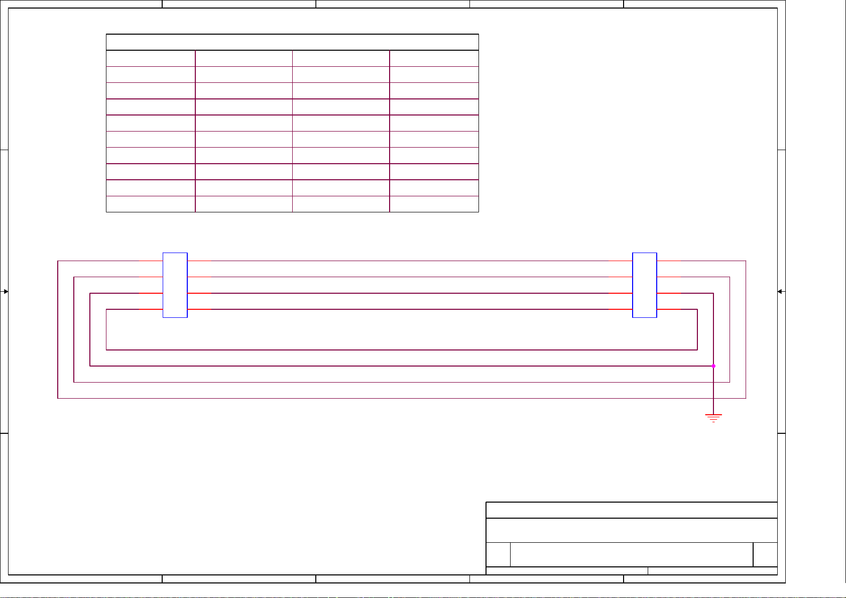
5
4
3
2
1
Pin Define
IF CN102 KEYPD CON
D D
2x4p 2.0mm 180degree 2x4p 2.0mm 180degree
1
2
3
5
6
7
8
C C
CN301
1 2
3 4
5 6
7 8
2x4P 2.0mm
From IF BD
CON CN301
2
1
4
344
6
5
8
7
CON CN302
2x4p 2.0mm 90degree
1
2
3
5
63
72
8
1x8p 1.25mm180degree
8
7
6
5
4
1
MENU
Auto
LED_A
LED_G
CN302
1 2
3 4
5 6
7 8
2x4P 2.0mm
To Keypad
RIGHT&Left
E-color
GND
POWER
B B
A A
Title
<Title>
Size Document Number Rev
<Doc> <RevCode>
A
of
5
4
3
Date: Sheet
2
11Thursday, July 17, 2008
1
Page 77
5
4
3
2
1
R827
11
12
7
8
9
10
10
SR5150PT
R828 10
D805
SR540PT
14
2
R835
33
C808
T801
SPW-0xx
1
2
3
5
6
3
C828
4700p/400V
3
LTV817M
IC801
D802
MUR1100ERL
1
R814
10K
C805
2200p/400V
R834
33
C806
4700p/400V
DC 650V Max
FB801
120Ω 3A
DC 650V Max
23
47p/1KV
R815
0R43 2W
+5V
ON/OFF
BRIGHTNESS
VOLUME 4
MUTE 4
DC 380V Max.
R805
COMP
4
0R2 1W
1N4003
D804
+
C807
10u/25V
6
OUT
CS
2
C814
100p/50V
C813
1000p/50V
R804
68K 2W
R816
1K
Q804
AP2761I
R813
10R
C827
0.1/50V
FB803
45Ω 3A
D D
D801
1
BL4-06
2
AC 264V RMS
4 1
C C
B B
A A
3 2
R801
330K
AC 264V RMS
C803
0.47/275V
F801
2A/250V
SW801
1 2 3
L
P801
AC_SKT
3
-+
4
L801
20mH
R802
330K
R803 330K
RT801
NTC 5R
C801
1000p/400V
C802
1000p/400V
N
5
C804
+
100u/450V
C811
2.2u/50V
AC 264V RMS AC 264V RMS
R806
150K
R810
3M
R811
3M
R809
3M
R812
330K 1%
R807
150K
C810
0.1/50V
R818
OVP
BNO
R819
100K 1%
C812
100P/50V
CN801
110mm 8PR
TO SCALER BD CN101
1M
8
1
LD7522
1
2
3
4
5
6
7
8
R808
150K
VCC
7
IC802
345
GND
(-)LATCH
C832
NC
C815
1000p/500V
D803
D807
SR5150PT
D806
SR540PT
C820
1000u/10V
C816
1000p/500V
+
R832
470 1%
R820
4.7K 1%
+
C817
1000u/25V
InnoLux
5uH
L802
5uH
L803
IC803
TLV431ALP
C819
470u/25V
C824
47u/25V
C821
0.47uF/63V
C
R
A
+
+
R821
1K 1%
R826
NC
ACER BV193
Document Number : SIZE :
TITLE :
POWER SUPPLY
DATE :
2008-04-25
SHEET OF
2
R830
200
C822
0.1/50V
R822
15.4k 1%
Rev :
ZD801
18V
R824
10k 1%
A4
V0442
1
R825 82K 1%
R823
100k 1%
APPRO BY :
CHECK BY :
DRAWN BY :
R829 10K
1
R831
100 2W
32
Q801
MMBT4401
F803
4A/32V
+
C826
0.1uF/50V
C829
NC
+16V
+5V
Page 78
5
4
3
2
1
+16V2,4
R505
C526
NC
5V
C508
NC
op1
op2
33
C505
1000p/50V
1
3
4
6
T501
SPW-068
R530
33
C522
1000p/50V
1
3
4
6
T502
SPW-068
8
C506
10p/3KV
7
C509
5p/3KV
C513
6800p/50V
8
C523
10p/3KV
7
C528
5p/3KV
C525
6800p/50V
R506
3M 3KV
R510
3K3 1%
3
C514
1000P/50V
R525
3M 3KV
R531
3K3 1%
3
C527
1000PF/50V
3
R541
NC
D509
BAV99
InnoLux
Document Number : SIZE :
TITLE :
ACEL19" (INL837)
3
R540
NC
1 2
2
D503
BAV99
1
D508 BAV99
2
1
2
1
Customdoc
D502
BAV99
R521
470
3
D504
BAV99
IS1
C530
2200p/50V
R529
470
3
D507
BAV99
IS2
C524
2200p/50V
APPRO BY :
CHECK BY :
C504
1000p/50V
1000p/50V
R520
30K 1%
D511
SN4148
D512
SN4148
R504
33
81
7
6
54
R532
33
C529
81
7
6
54
R519
1M
C521 220p/50V
C501
220u/35V
2
3
2
3
U501
AP9971GD
U502
AP9971GD
C531
R507
3M3 1%
R535 15
C511 0.047/25V
R516 604K 1%
R526
1M
220u/35V
R508
43K 1%
C512 270p/50V
D505
SN4148
C502
C520
0.1/50V
C516 1000p/50V
IS1
IS2
2.2u/25V
5V
C515
2.2u/16V
C519
0.1/50V
FB802 85Ω
D D
R517 33
+5V2
C503
NC
R522
200K
C C
BRIGHTNESS2
B B
ON/OFF2
A A
R512
10K
R501
10K
C510
1000p/50V
R542
200K
R518
470K 1%
R514
150K 1%
C507
2.2u/16V
R513
100K 1%
R515
1M 1%
C518
0.01/50V
1
DRV1
2
VDDA
3
DIM
4
ISEN
5
PID
6
RSTR
7
RT
8 9
ENA VSEN
IC501
INL837
R539
5K1 1%
D506
BAT54
C517
5600p/50V
SSTCMP
R537
10K 1%
3
R538
10K 1%
DRV2
GNDA
TIMER
LCT
OVPT
R534 15
CT
1
2
16
15
14
13
12
11
10
op1
op2
R524
200
1
2
R527
200
1
2
R528
820 1%
1
2
1
2
R523
820 1%
1
2
1
2
H
CN501
4100-D02
L
H
CN502
4100-D02
L
R536
15K 1%
H
CN503
4100-D02
L
H
CN504
4100-D02
L
R533
15K 1%
DATE :
SHEET OF
5
4
3
2007-12-12
2
Rev :
V0444
DRAWN BY :
1
Page 79
5
D D
Line_R
4
R701
2.2K
3
U701
TDA7496SA
C703
0.1/50V
Audiio +16V
+
C702
470u/25V
2
FERR BEAD
FB703
1
+16V 2,3
Line_L
R702
Q704
1
C714
10u/16V
D702
ESD
1 2
32
10K
R719
1
2.2K
R708 4K7
R711 5K6
32
Q701
PMBT3904
C701 10u/25V
+
R709 10K
D701
ESD
FB701
600Ω
Audiio +16V
R704
R705
C C
B B
30K
R714
30K
MUTE2
47K
32
Q703
1
PMBT3904
VOLUME2
R717 10K
R703 10K
PMBT3904
R718
1K
Audiio +16V
1 2
32
Q702
1
C715
+
220u/16V
R712 5K6
R713 100
R7155K1
PMBT3904
R710 10K
C704 0.47/16V
C706 0.47/16V
C710 4700p/50V
C711 4700p/50V
FB702 FERR BEAD
5
1
8
10
9
3
6
13
INL
INR
S_GND
MUTE
STBY
VOLUME
NC
11
VS
OUTL
OUTR
SVR
VAROUT_R
VAROUT_L
GND
GND
15
12
14
7
2
4
新增加的EMI 對策。2008/01/16
C709 0.1/50V
+
C708 470u/16V
+
C705220u/16V
+
C707220u/16V
R706 1K
R707 1K
Left Out
Right Out
CN701
4
3
2
1
4P 2.0mm 90°
P701
AUDIO IN
A A
2
3
4
5
1
Line_R
Document Number : SIZE :
Line_L
TITLE :
DATE :
SHEET OF
5
4
3
InnoLux
ACEL19" (INL837)
2007-10-16
2
Rev :
APPRO BY :
A4doc
CHECK BY :
DRAWN BY :
0144
1
Page 80
Acer Acer –LCD-BV203H
1.R
180 d
t
7.0 Assembly and Disassembly
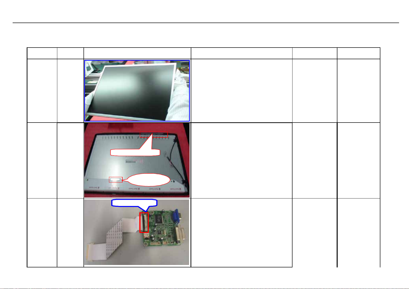
The tool of Assembly and disassembly : 1) Electrostatic gloves 2) Electric screwdriver: the lengthe of screwdriver top is 6±0.5cm and
15±0.5cm ; the diameter of screwdriver top is Φ5*H5mm
Sequence Item Photo Procedures P/N
(1).Take panel out of box and place it on
the foam .
(2).Tear open th e P E bag an d p u t it in
the des ignated c arton.
(3).Place panel on the foam like the
attached p icture.
R emark:Do n ot to u ch th e lamp c ord a n d
place the su rface of panel downsides on
the cushion.
everse the panel by
the su rface of panel upsides an d insert
front b e zel in th e p a n el.
2.Reverse the panel by 180 degree using
both hands,put the surface of panel
downsides and m ake su re FFC interface
is closer to operator.
3.Paste tinfoil on th e p o sition wh ich re fers
to atta ch e d p ictu re,in ord er to co ver th e
g a p in th e pa nel c o mple t ely .
Remark:Make su re the fixed job is
fin ished properly and lam p wire is closer
to right h and ;M ake the tinfoil sm ooth in
egree,pu
631102200450RA
714030023501R
S1
S2
Place
panel
Assemble
fro nt
bezel
FFC cable
keypad
Description
LCP
20.0"LTM200KT01
A02(A)(SAM SUNG
)R O H S
ASSY,
BEZEL,BLACK,SE
C,LE20N9
e
In s e rt F FC w ire in to it s re le va n t in t e rfa c e
of mainb oard properly like attached
picture
S3
LVDS interfac
Fix
m ainboar
d
70
792471300811R
PCBA,I/F
BOARD(EMEA,W /
O),LE20N8-812
ROHS
Page 81
Acer Acer –LCD-BV203H
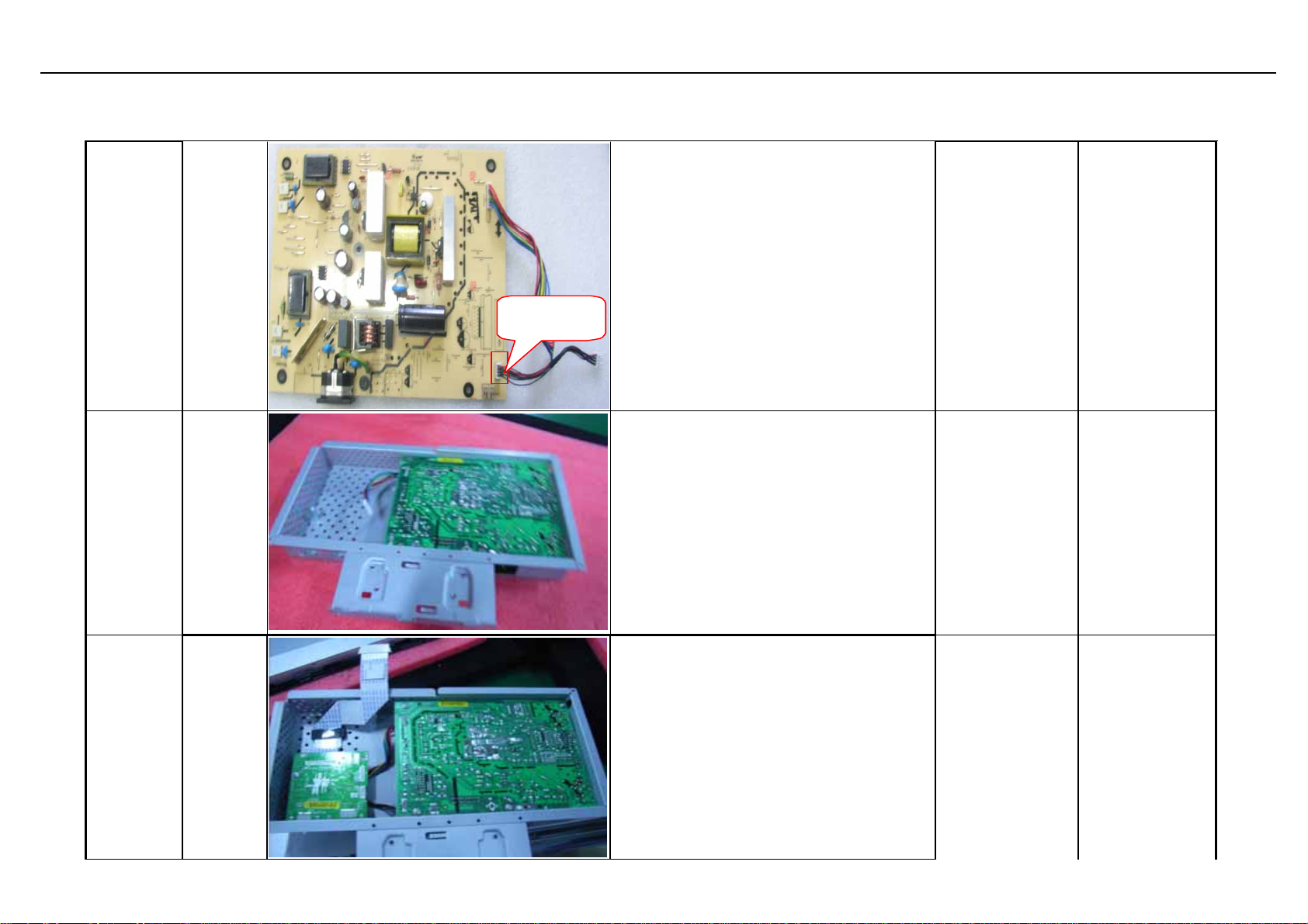
Assembly and Disassembly (continue)
S4
S5
Fix
powerboa
rd
Fix
chassis
&p oweb o
ard
short
keypad
Insert short keypad cable its relevant
interface of powerboard p roperly like
attached pictu re
Place th e chass is on th e cu s h ion after
chec k ing , p u t th e p owerboard into th e
cushion as picture
792291400810R
701000014003R
PCBA,P/I
BOARD,W /O
SPK,LE20M2812 ROHS
ASSY,CHASSIS
,W/O SPK,SEC
,LE 2 0 N 9
1.L ink m ain b oard an d p ower board as
pictu re, an d make s u re th e cab le in th e
correct position
2. P u t th e main board in to th e ch as sis
and mak e su re th e F FC c ab le is OK
S6
link main
board and
powerboa
rd
71
792291400810R
PCBA,P/I
BOARD,W /O
SPK,LE20M2812 ROHS
Page 82
Acer Acer –LCD-BV203H
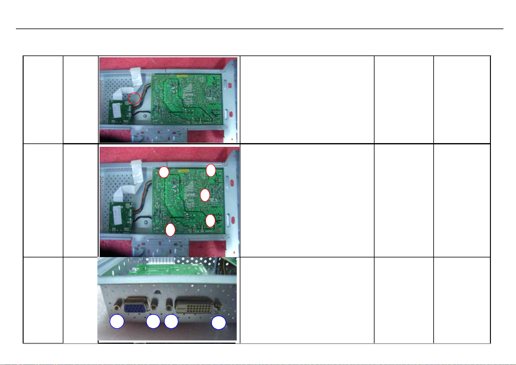
Assembly and Disassembly (continue)
S7
S8
Twist
PCBA
screw
Twist
PCBA
screw
Handle electric opener and on e pcs of
M3*6 screw
3
5
2
4
Fix 5 pcs of screws separately on the
poweboard and mainboard like the
attached Picture1
(1). Handle hexagonal screws and
Twist
S9
Hexagonal
screws
2
34
1
elect ric opener
(2). Twist screw in the interface like the
attached Picture1.
(3). Place cu shi on on the designated
locat ion aft er iron frame is taken away.
72
Page 83
Acer Acer –LCD-BV203H
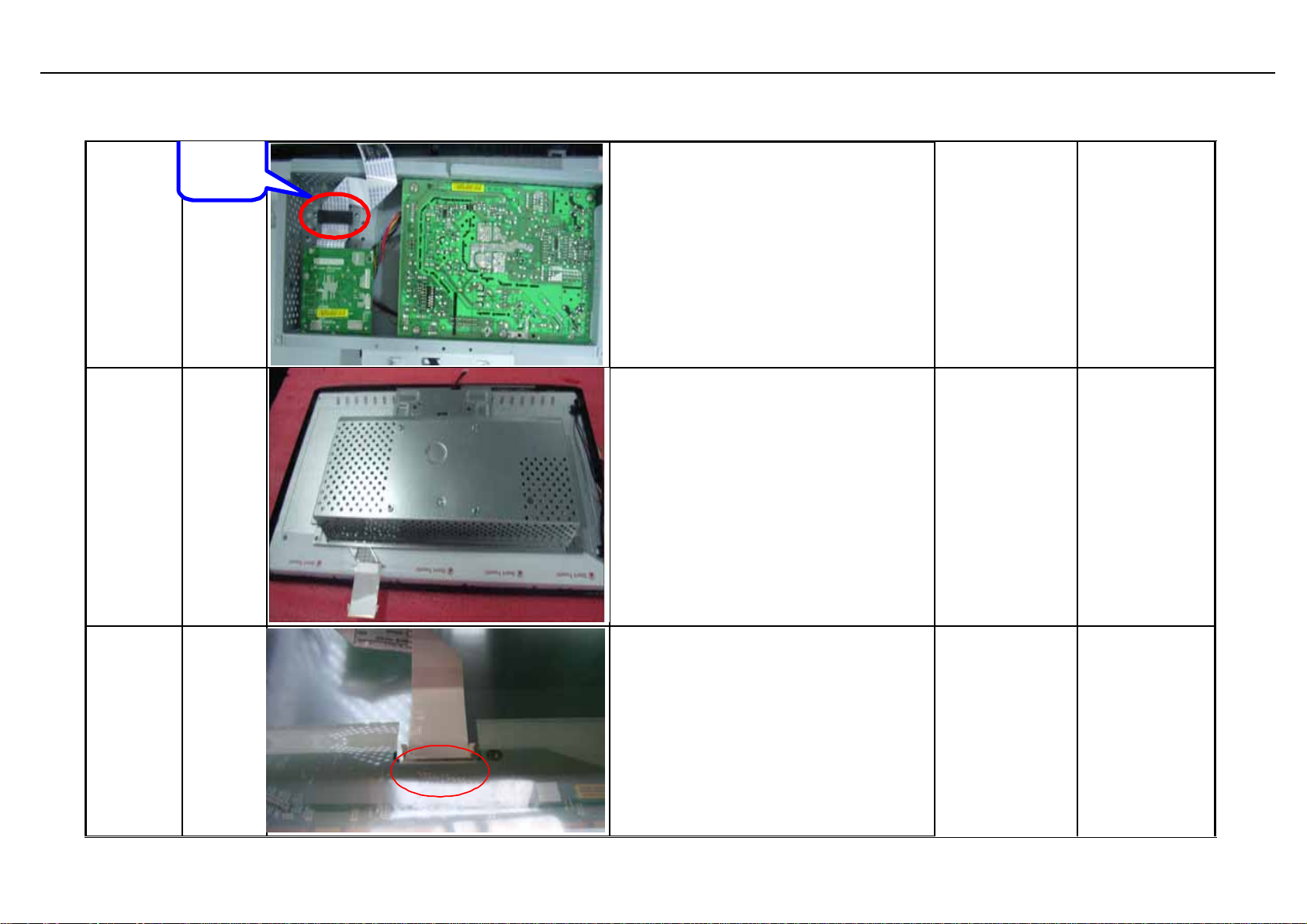
Assembly and Disassembly (continue)
magnet
loop
S10 Fix chassis
Assemble
S11
chassis
Insert FFC
S12
cable
put the magnet loop fix into the front
beze l as picture
1)Fix chassis on the back of panel and
front bezel
2)P u t lamp wire a n d FFC wir e in order as
picture
1.Tear off the adhensive tape of FFC
wire;
2.Insert FF C wi re i n to the in terfa ce of
pane l
3.Put FFC wire in order and paste them
on the panel
4.Fix chassis on the back of panel
701000014003R
701000014003R
430303001500R
ASSY,CH ASSIS
,W/O SPK,SEC
,LE20N9
ASSY,CH ASSIS
,W/O SPK,SEC
,LE20N9
HRN LVDS FFC
30P 182mm
ROHS
73
Page 84
Acer Acer –LCD-BV203H
Assembly and Disassembly (continue)
S13
S14
Insert light
wire
Assemble
Speaker
Inse rt 4pcs l ight wire into the r elev ant
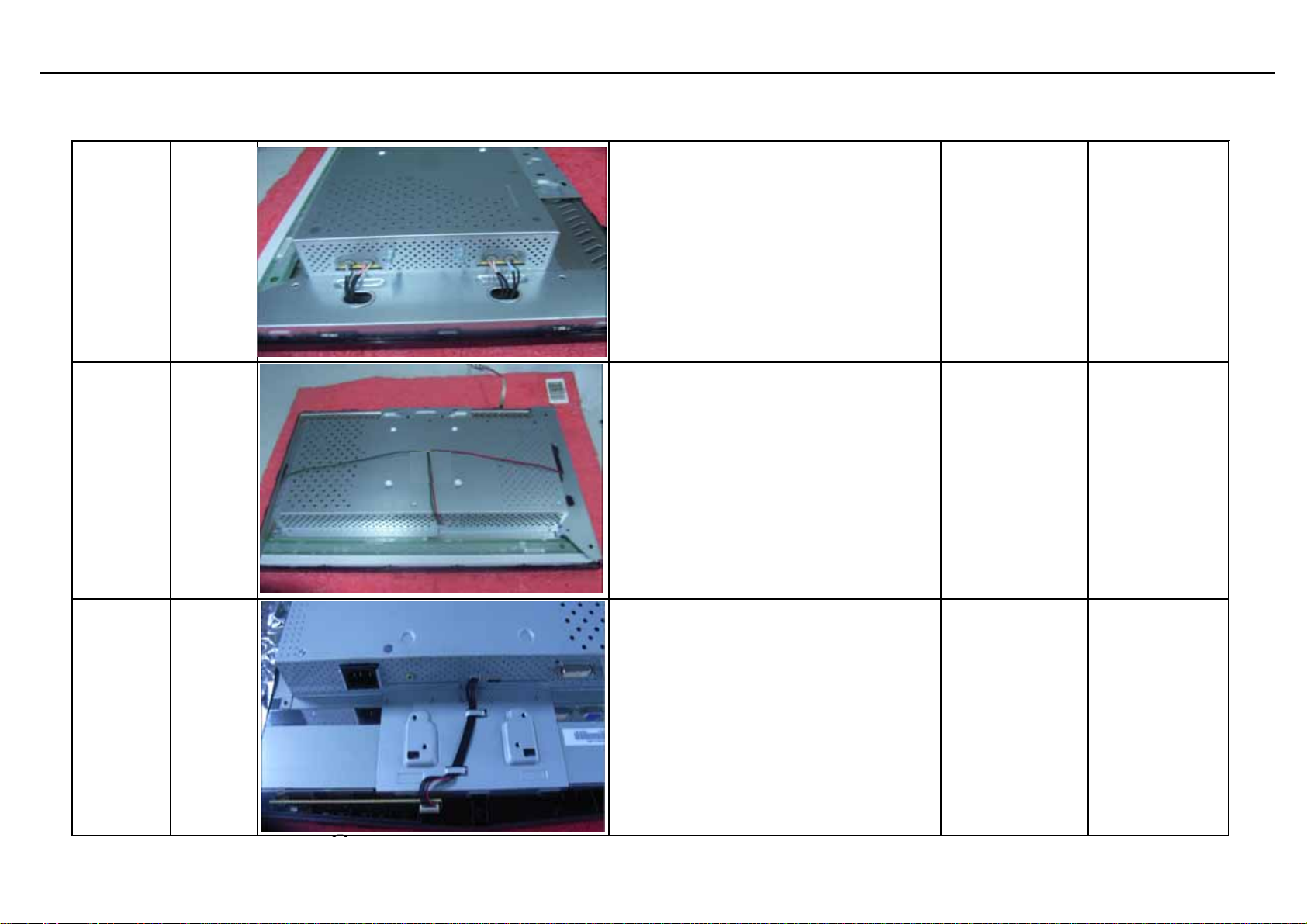
position as picture
Put 2pcs speaker into the chassis of right
and left as picture
S15
Assemble
keypad
cable
Put the kaypad cable into the right
position of chassis as picture
74
Page 85
Acer Acer –LCD-BV203H
3
Assembly and Disassembly
S16
Fix back
cover
S17 Fix stand
3
2
1
4
3
2
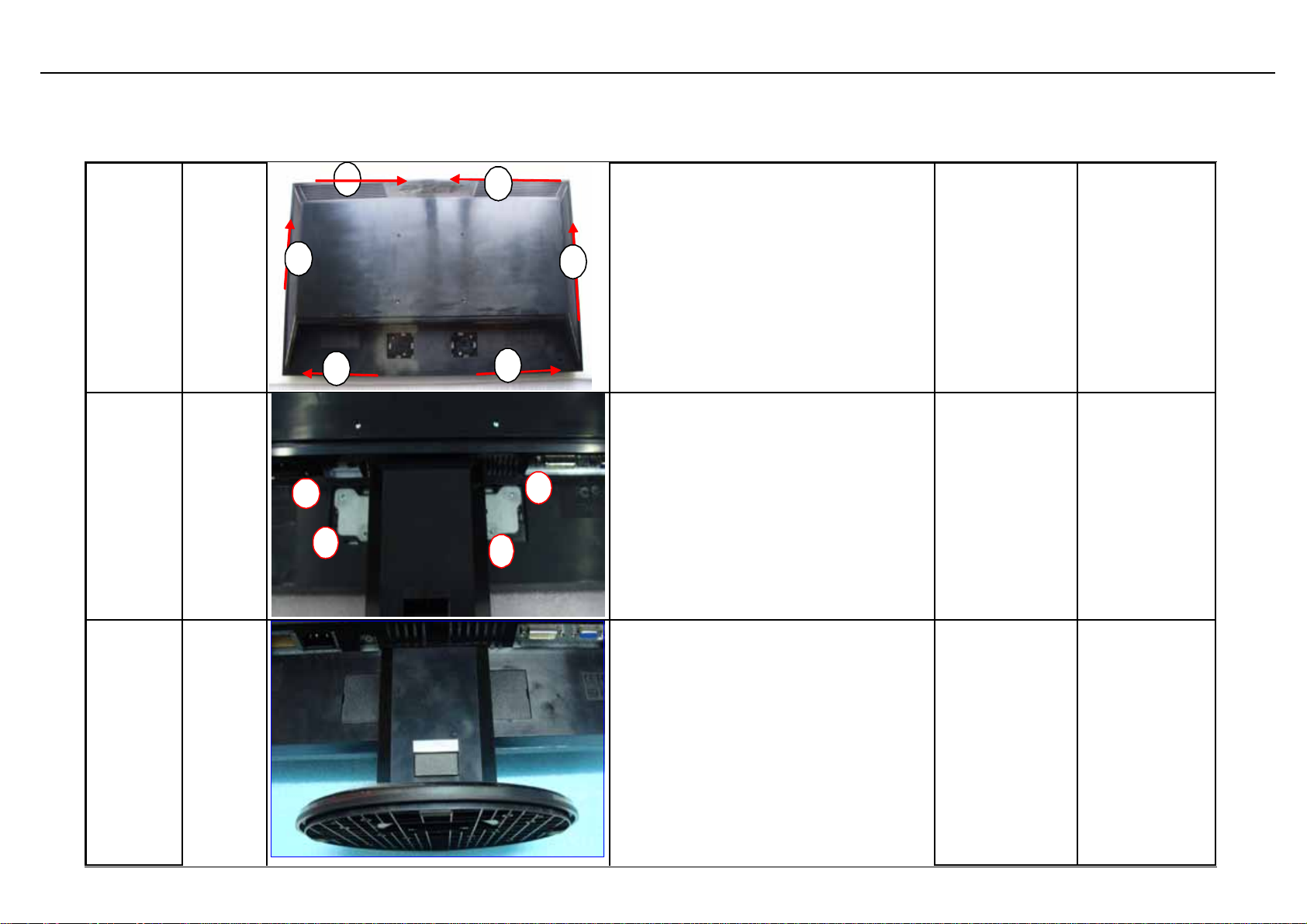
Check if back cover is fixed properly
714050021903R
ASSY
COVER,W/O SPK
,BLACK,LE20N9SEC
1
1
Use 4pc s scr ew fix stand on the back of
assemble like attac hed Picture
501020220020R
COVER
HINGE,BLACK
RIGHT,LE19D1
2
S19
Assemble
cover
Assemble t he cover hin ge into the stan d
as picture
hinge
75
714020017500R
ASSY,BASE,LE21
M4
 Loading...