

Page 1
& K DSWHU
System Housing
This chapter describes the things to consider when setting up and
installing additional components to your system.
1.1 Front and Rear Panel Features
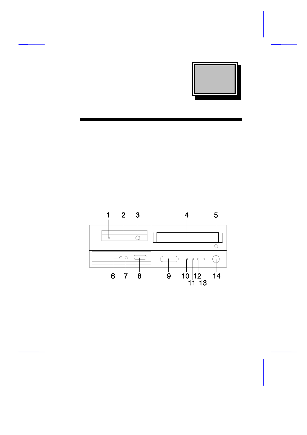
1.1.1 Front Panel Features
Most of the connectors on the computer are f ound at the rear of the
unit. A few connectors are found on the fr ont for easy access. Let’s
take a look at the front and rear of the unit before we make the
connections.
Figure 1-1 Front Panel Features
System Housing 1-1
Page 2

Table 1-1 Front Panel Features
# Item Description
1 Floppy disk drive activity
indicator
2 Floppy disk drive Accepts 3.5-inch, 1.44MB diskette
3 Floppy disk drive eject
button
4 CD-ROM drive Accepts a CD-ROM disc
5 CD-ROM drive open/close
button
6 On/sleep button Turns the computer on and off
7 Power/suspend indicator Lights green when on; lights orange
8 Hard disk/message
indicator
9 Network active indicator Flashes when your computer is
10 Network link indicator Lights when the computer is connected
11 Infrared receiver Receives input from the wireless
12 Game/MIDI port Connects a joystick, game device or
13 Microphone jack Connects a microphone
14 Earphone/headphone jack Connects an earphone or headphone
Lights up when the floppy disk drive is
being accessed
Ejects the diskette from the floppy disk
drive
Opens and closes the CD-ROM drive
when in suspend mode
1
Flashes when your hard disk drive is in
use
communicating with the network
to a network
keyboard or remote control
MIDI device
1
Your computer enters s uspend mode when the suspend timer ti mes out. You can
also put the computer i n suspend mode by selecting t he S uspend command from
the Start menu.
1-2 User’s Guide
Page 3
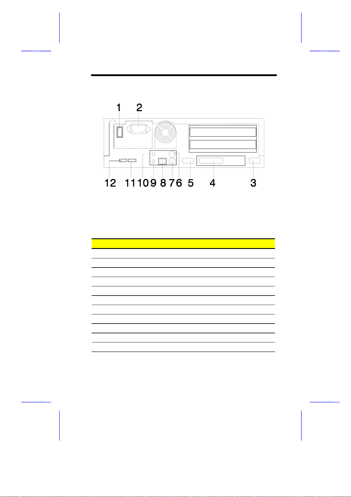
1.1.2 Rear Panel Features
Figure 1-2 Rear Panel Features
Table 1-2 Rear Panel Features
# Item Description
1 On/off switch Turns power on and off
2 Power cord socket Connects a power cord
3 External CRT port Connects an external monitor
4 Parallel port Connects a printer or other parallel device
5 Serial port Connect a serial mouse or other serial device
6 PS/2 keyboard port Connects a PS/2 keyboard
7 PS/2 mouse port Connects a PS/2 mouse
8 Speaker port Connects to speakers
9 Microphone port Connects a microphone
10 USB port 2 Connects a USB device
11 USB port 1 Connects a USB device
System Housing 1-3
Page 4
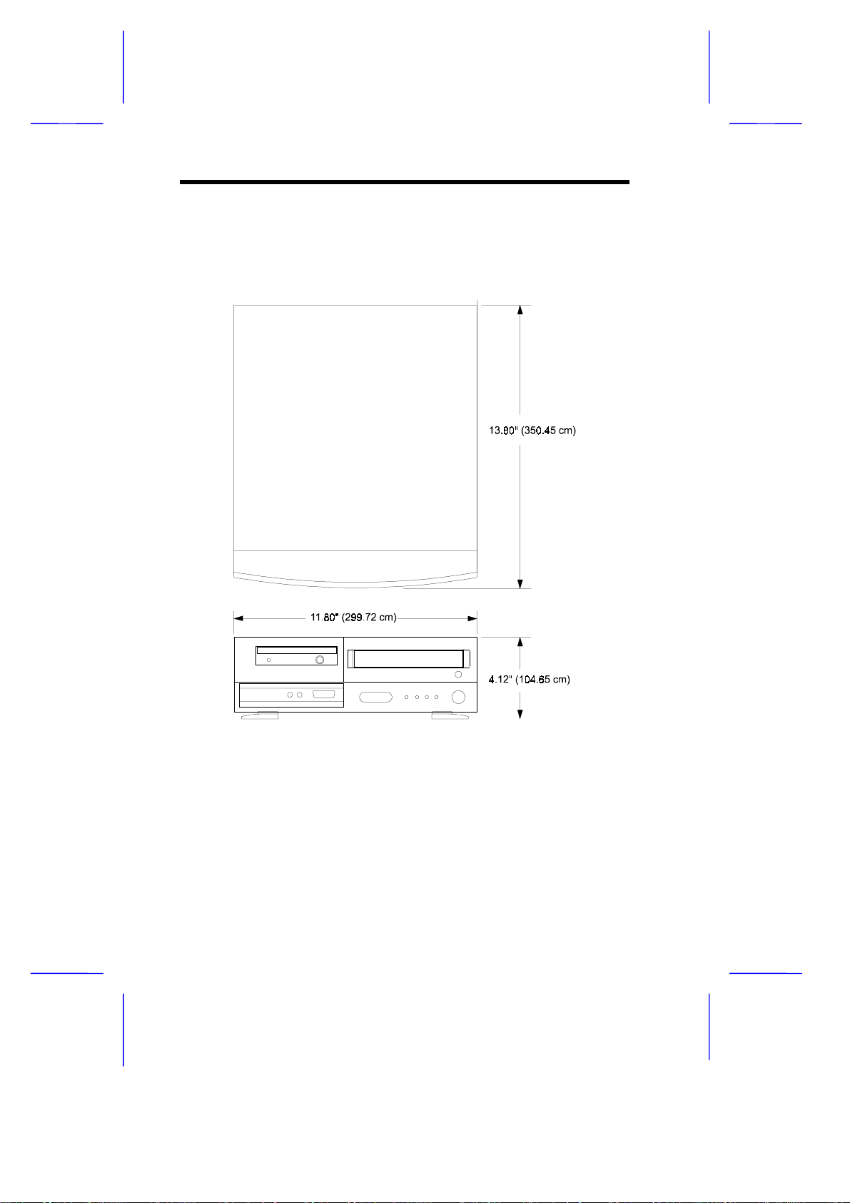
1.2 Finding a Suitable Area to Install the System
This system has the following dimensions.
Figure 1-3 System Dimensions
Locate a suitable area to place the system. Allow ample spac e on all
sides of the unit for cords and cable connections. The system should
also be placed near the devices you will connect to it.
1-4 User’s Guide
Page 5
1.3 Basic Connections
These are the basic connections you need to get your system up and
going. You can also connect options like a printer or the phone line,
described in the following sections.
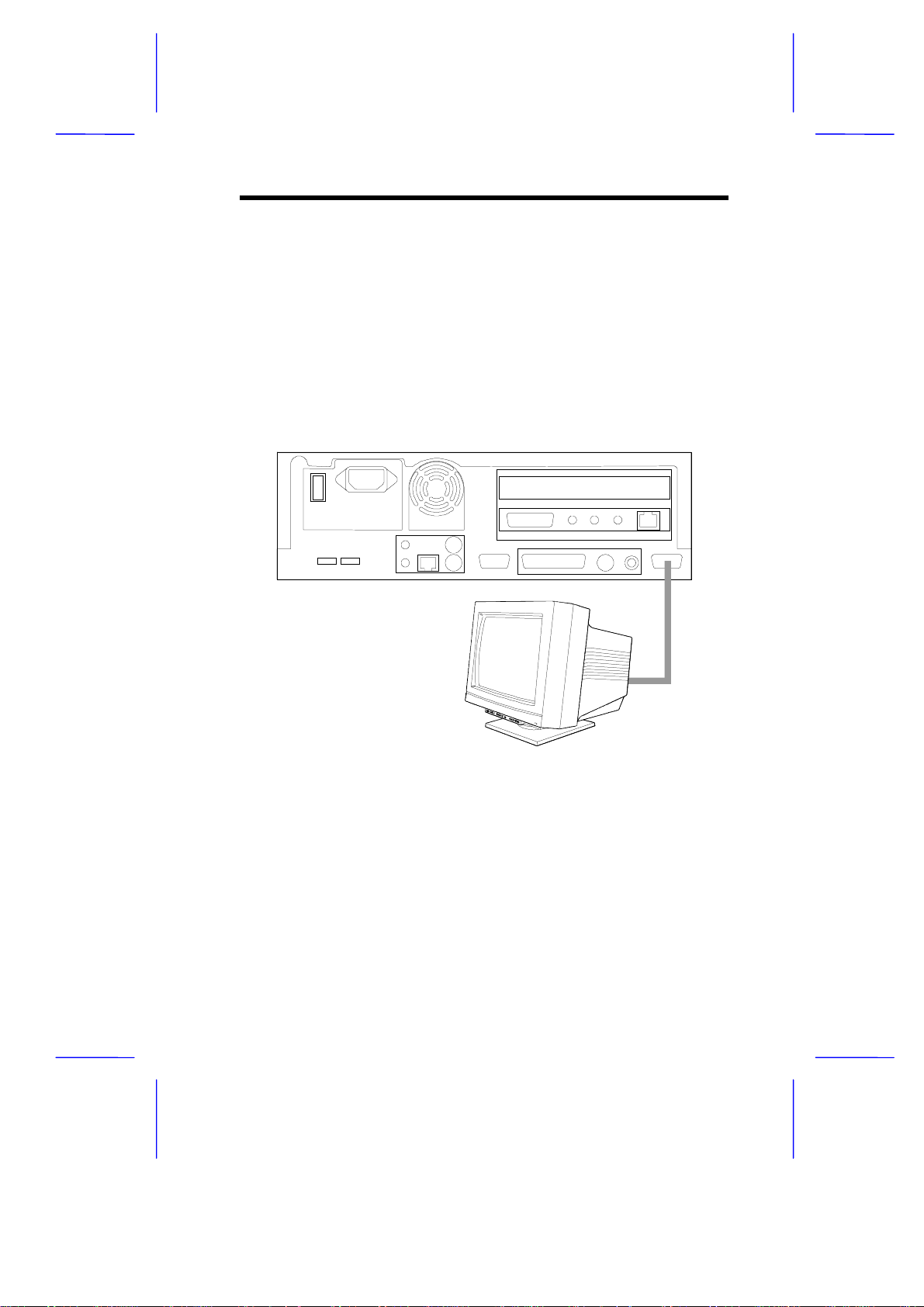
1.3.1 Connecting to a Monitor
First you need to connect an output device to the computer such as a
monitor.
Figure 1-4 Connecting to a TV or Monitor
System Housing 1-5
Page 6
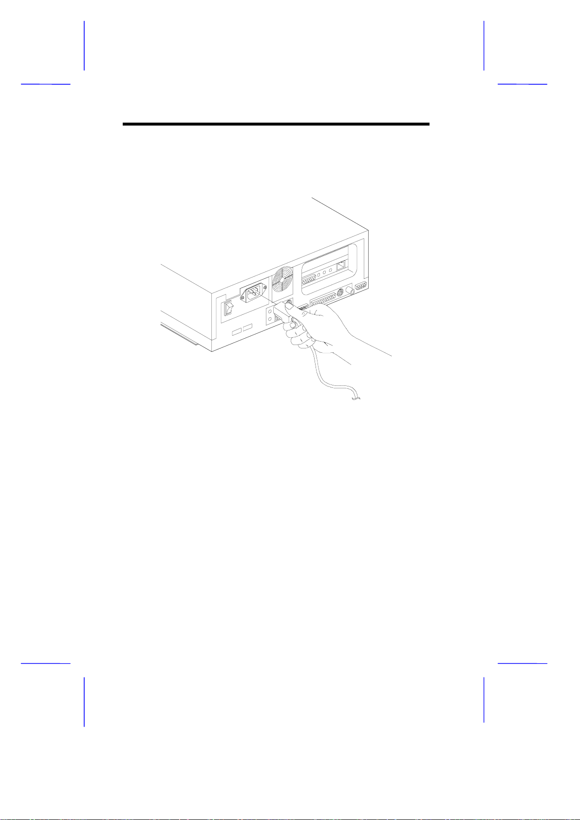
1.3.2 Connecting the Power Cord
Connect the power cord to the power cord socket at the rear of the
unit. Then connect the other end to a properly ground power outlet.
Figure 1-5 Connecting the Power Cord
These basic connections you’ve just made are all you need to get your
system up and running. If you need to make other connec tions such
as a phone line (for connecting to the Internet) or a printer (for printing
documents), read on.
1-6 User’s Guide
Page 7
1.4 Connecting Options
Other connections you make to your computer include the following:
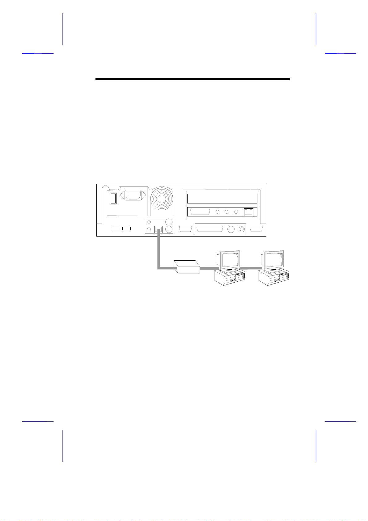
1.4.1 Network Line
You can connect the system to a network with the built-in 10BaseT
(Ethernet) jack found at the rear of the unit. Computers in most
companies are connected on networks to facilitate the transfer of
information.
Figure 1-6 Connecting the System to a Network
If you are using the system in a networked envir onment, contact your
system administrator for details.
System Housing 1-7
Page 8
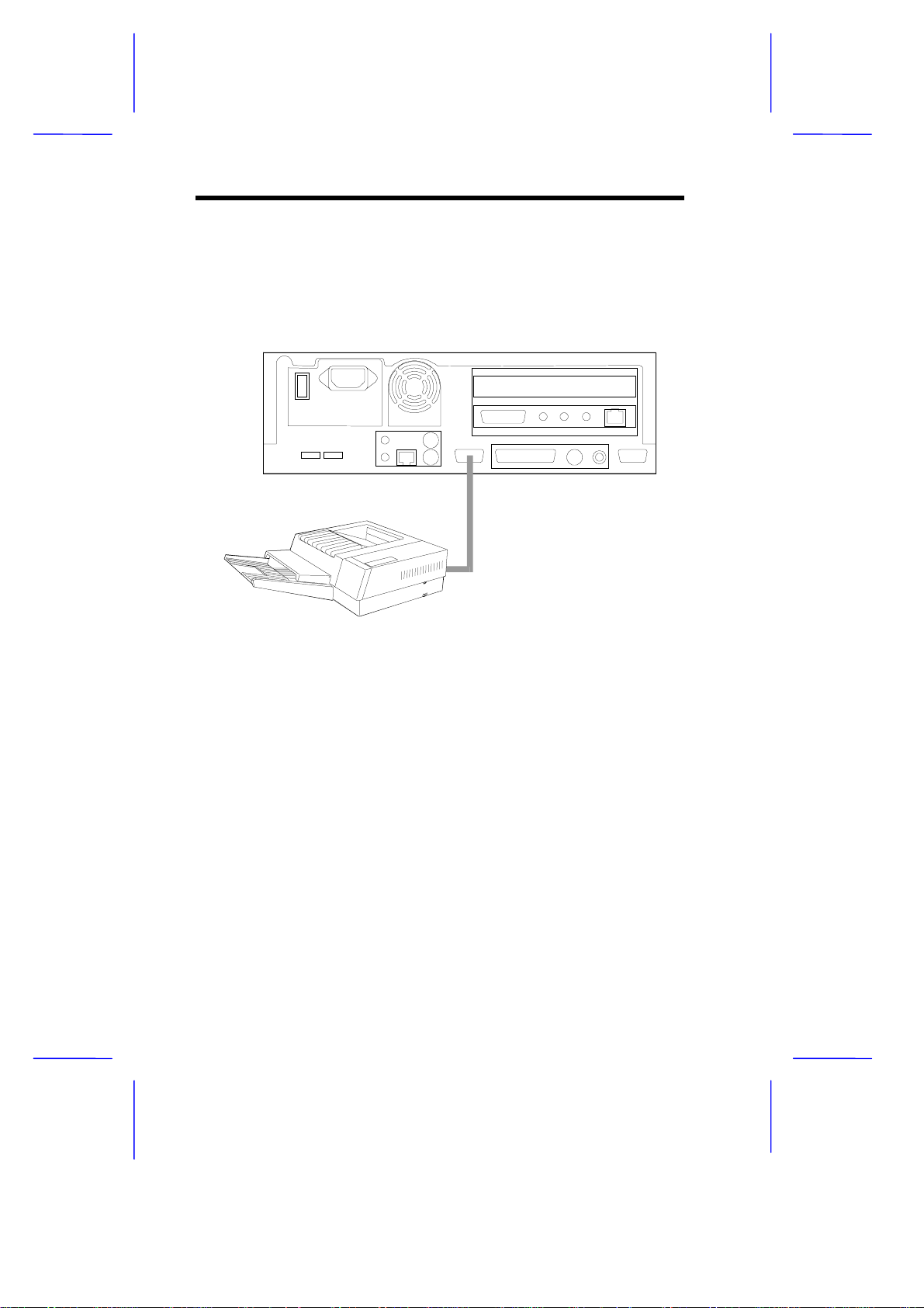
1.4.2 Printer
A printer allows you to print out documents and other data from your
computer to paper. Connect a printer to the parallel port found at the
rear of the unit.
Figure 1-7 Connecting the System to a Printer
1-8 User’s Guide
Page 9
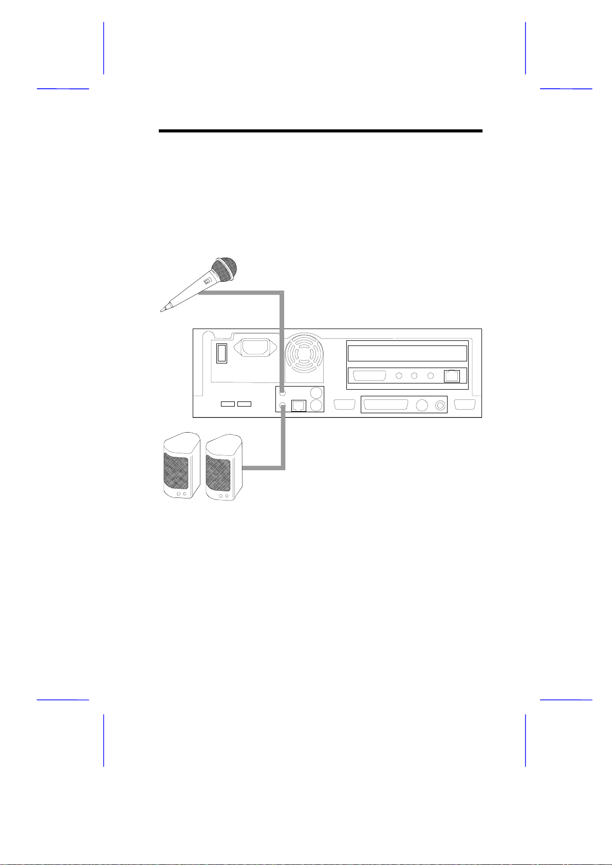
1.4.3 Audio and Game Devices
You can connect various audio and game devices to your com puter.
Some of these ports are duplicated in the front of the unit for easy
connection.
At the rear of the unit:
Figure 1-8 Rear Connector
❍ speakers connect to the speaker out jack
❍ microphone connects to the microphone jack
System Housing 1-9
Page 10

At the front of the unit:
Figure 1-9 Front Connectors
❍ earphones or headphones connect to the earphone/ headphone
jack
❍ microphone connects to the microphone jack
❍ joystick, game or MIDI device connects to the game/MIDI port
1-10 User’s Guide
Page 11

1.4.4 External Keyboard
There are two types of keyboards that you can use with the system:
❍ USB keyboard connects to any of the two USB ports
❍ PS/2 keyboard connects to the PS/2 keyboard port
These ports are found on the rear of the unit.
Figure 1-10 Connecting the Keyboard
System Housing 1-11
Page 12

1.4.5 External Mouse
There are three types of mice that you can use with the system:
❍ USB mouse connects to any of the two USB ports
❍ PS/2 mouse connects to the PS/2 mouse port
❍ Serial mouse connects to the serial port
These ports are found on the rear of the unit.
Figure 1-11 Connecting the Mouse
1-12 User’s Guide
Page 13

1.5 Component Installation
Observe the ESD Precautions before ins talling a
system component.
1.5.1 ESD Precautions
Always observe the following electrostatic discharge (ESD)
precautions before installing a system component:
1. Do not remove a component from its anti-static packaging until
you are ready to install it.
2. Wear a wrist grounding strap before handling electronic
components. Wrist grounding straps are available at most
electronic component stores.
System Housing 1-13
Page 14

1.5.2 Opening the Housing
1.
Use the screw driver to unscrew the cover of the housing, as
shown below.
Figure 1-12 Removing the Housing Screws
2.
Push open the cover then gently lift it up until it detaches from the
body frame.
Figure 1-13 Detaching the Top Cover
1-14 User’s Guide
Page 15

1.5.3 Removing the Disk Drive Metal Frame
The metal frame gives additional support to the housing’s structure.
You can install one 3.5-inch drive, one CD-ROM drive and one hard
disk drive in the disk drive metal frame.
To remove the disk drive metal frame:
1. Insert two fingers into the hole. Gently draw it back as you lift it up.
Figure 1-14 Removing the Metal Frame
2. To remove the metal disk drive frame, first unscrew the frame
using a screw driver. The screw is located on the lower-left side of
the frame. Then gently detach the disk frame from the housing.
System Housing 1-15
Page 16

Figure 1-15 Removing the Disk Frame
3. Unscrew the hard disk drive frame to detach as shown below.
Figure 1-16 Removing the Hard Disk Drive Frame
1-16 User’s Guide
Page 17

Installing a Hard Disk Drive
1.
Attach the hard disk drive to the hard disk drive frame with the
necessary screws as shown below.
Figure 1-17 Installing the Hard Disk into the Hard Disk Drive
Frame
2. Reattached the hard disk drive frame to the disk frame.
Figure 1-18 Reattaching the Hard Disk Drive Frame to the Disk
Frame
System Housing 1-17
Page 18

Installing a 3.5-inch Diskette Drive
1.
Attach the 3.5-inch diskette drive to the 3.5-inch diskette drive with
the necessary screws as shown below.
Figure 1-19 Installing a 3.5-inch Disk Drive into 3.5-inch Drive
Frame
1-18 User’s Guide
Page 19

Installing a CD-ROM Drive
1. Attach the CD-ROM drive to the CD-ROM drive with the necessary
screws as shown below.
Figure 1-20 Installing a CD-ROM Drive
System Housing 1-19
Page 20

1.5.4 Installing a System Board
Installation Procedures
1. Align the board with the pegs on the housing frame.
Figure 1-21 Installing the System Board
2. Gently press the board until it is properly seated.
3. Secure the board with the required screws.
1-20 User’s Guide
Page 21

4. Attached the USB connector cable to the system board. Using a
screw driver, secure the connector to the housing’s opening at the
back. The USB connector opening is located on the lower-left side
of the housing (at the back).
Figure 1-22 Attaching the USB Connector Cable to the System
Board
For more information about the system
board’s connectors, please refer to the
system board’s manual.
5. Secure the Front I/O Board (located in front of the housing) with
the appropriate screw as shown below.
System Housing 1-21
Page 22

Figure 1-23 Installing the Front I/O Board
6. Attach the appropriate cables as shown below.
Figure 1-24 Attaching the Front I/O Board Cables
1-22 User’s Guide
Page 23

1.5.5 Installing the Power Supply
Before you attach the power supply, make sure
that you have installed the system board.
1.
Connect the power supply cables into the onboard power
connector.
2. Install the power supply into the housing frame. To install, sim ply
insert the frame tabs into the appropriate holes on the rear panel.
Figure 1-25 Installing and Securing the Power Supply
3. Secure the power supply with the required screw.
System Housing 1-23
Page 24

1.6 Reinstalling the Disk Drive Metal Frame
1. Reinstall the drive frames with drive(s) to the housing. Secure the
metal frame with the required screw.
Figure 1-26 Reattaching the Disk Drive Metal Frame
2. Attach the power supply and drive cables. Make sure that the
hard disk drive cable is connected to the IDE1 c onnector on the
board.
1-24 User’s Guide
Page 25

1.7 Installing Expansion Boards
Observe the ESD Precautions (see section
1.5.1) before installing a system component.
1. Insert the Riser Card into the system board as shown below.
Figure 1-27 Installing the Riser Card
2. Study the expansion board installation guide and configure any
jumpers as directed.
System Housing 1-25
Page 26

3. Remove a bracket from any empty expansion slot. Save the
screw to secure the new board. Keep the bracket for future use.
Figure 1-28 Removing the Bracket from an Empty Slot
4. Gently insert the board into the expansion slot. Make sure that the
board is properly inserted.
Figure 1-29 Inserting the Board into an Expansion Slot
5. Secure the board with the screw.
Do not neglect this step. The board uses the
1-26 User’s Guide
Page 27

screw for grounding.
1.8 Replacing the Cover
After you install the necessary system components into the housing,
you must reinstall the cover.
To install the cover:
1.
Reinstall the metal frame by gently sliding it in while pushing it
down.. The metal frame should rest perfectly between the
housing’s frame.
Figure 1-30 Reinstalling the Metal Disk Drive Frame
2.
Align the corners of the cover with the fram e of the housing and
push the cover back until it clicks into place..
System Housing 1-27
Page 28

Figure 1-31 Reinstalling the Cover
3.
Secure the cover with the appropriate screws.
Figure 1-32 Securing the Screws to the Cover
1-28 User’s Guide
 Loading...