

Page 1

Acer Acer –LCD-B243HL
Service Manual
LCD Monitor Acer B243HL
- 0 -
Page 2

1
Table of Contents
Important Safety Notice ........................................................................................02
01 Product Specification .......................................................................................... 03
02 Flat Panel Specification ......................................................................................21
03 Exploded Diagram ..............................................................................................47
04 Troubleshooting.................................................................................................... 49
05 Spare Parts List ..................................................................................................54
06 Schematics and Layouts ...................................................................................... 58
07 Assembly and Disassembly ................................................................................ 73
Appendix : User’s manual
Copyright
Copyright 2006 InnoLux Tech. Corp. Ltd
All Rights Reserved
This manual may not, in whole or in part, be copied, Photocopied, reproduced, translated, or converted to any
electronic or machine readable form without prior written permission of InnoLux Tech. Corp. Ltd.
Acer B243HL Service Manual
1
Page 3

Acer Acer –LCD-B243HL
Important Safety Notice
1. Safety precautions
This monitor is manufactured and tested on a ground principle that a user’s safety comes first.
However, improper used or installation may cause damage to the monitor as well as to the user.
Warning:
z This monitor should be operated only at the correct power sources indicated on the label on the
rear of the monitor. If you’re unsure of the power supply in you residence, consult your local dealer
or Power Company.
z Do not try to repair the monitor by yourself, as it contains no user-serviceable parts. This monitor
should only be repaired by a qualified technician.
z Do not remove the monitor cabinet. There are high-voltage parts inside that may cause electric
shock to human bodies.
z Stop using the monitor if the cabinet is damaged. Have it checked by a service technician.
z Put your monitor only in a lean, cool, dry environment. If it gets wet, unplug the power cable
immediately and consult your closed dealer.
z Always unplug the monitor before cleaning it. Clean the cabinet with a clean, dry cloth. Apply
non-ammonia based cleaner onto the cloth, not directly onto the class screen.
z Do not place heavy objects on the monitor or power cord.
2. Product safety notice
Many electrical and mechanical parts in this chassis have special safety visual inspections and the
protection afforded by them cannot necessarily be obtained by using replacement components rated
for higher voltage, wattage, etc. Before replacing any of these components read the parts list in this
manual carefully. The use of substitute replacement parts, which do not have the same safety
characteristics as specified in the parts list, may create shock, fire, or other hazards.
3. Service notes
z When replacing parts or circuit boards, clamp the lead wires around terminals before soldering.
z Keep wires away from high voltage, high temperature components and sharp edges.
z Keep wires in their original position so as to reduce interference.
z Adjustment of this product please refers to the user’ manual.
2
Page 4

Acer Acer –LCD-B243HL
01 Product Specification
1.
General:
Acer B243HL is designed with LVDS interface and VGA/DVI-D input, it featured with embedded
universal AC power supplies and audio input. It’s a green product and meets all ROHS standard. The
power button and display control buttons are on the front of the monitor. The monitors shall
automatically to display lower resolution video modes into 1920x1080 full screen display. The image
can be adjusted through OSD control. It support HDCP and color management function.
1.1 Main Features
1.1.1 For AUO M240HW01-V0 panel
Maximum resolution : 1920(x3) x 1080 @ 60Hz
Back light system : 2 bar Led
Pixel pitch : 276.75 um (H) x 276.75 um (V)
Display area : 531.36mm (H) x 298.89mm (V)
Brightness : 250cd/m² (TYP.)
Contrast ratio : 1000׃1 (TYP.)
ACM :80000:1 (Max)
Response time (Tr+Tf) : 5ms (TYP. ON/OFF)
Viewing angle : 170° (H)/ 160°(V), (TYP.)
Input interface : Analog (D-sub 15 pin)
Digital Option (DVI-D 24 pin )
Power management : Compatible with VESA DPMS
Plug & Play : VESA DDCCI
OSD language : English, French, Spanish, Italian, Deutsch,
Simplified Chinese, Traditional Chinese, Japanese
(Dutch, Finnish, Russian depend on sale region)
Universal AC power supply
1.1.2 Oth er mai n func tio n fe atu res
z Input interface : VGA/DVI/USB upstream
z VGA input : D-Sub
z DVI input : DVI-D
z USB : Support USB2.0 (optional function)
1.2 Accessories
AC Power Cord : 1.8 m. (Black. Cord type depend on sale region)
VGA cable : 1.8 m. (15 pin D-SUB, black cable with blue male connector)
User manual : English (640Mb CD)
DVI cable (option) : 1.8 m. (18+1 pin, black cable with white connector)
3
Page 5
Acer Acer –LCD-B243HL
USB cable(option) : 1.8m.(4pin, black cable with white connector)
Audio cable(option) : 1.8m.( green cable with white connector)
2.
Operation Specifications
The unit should suffer no visible cosmetic damage and should operate with no degradation in display quality
during exposure to the operating conditions and after exposure to the non-operating conditions, in any
sequence.
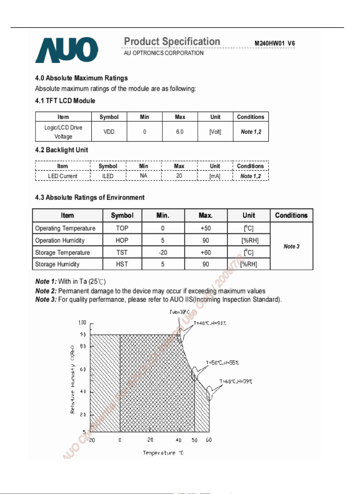
2.1 Environmental conditions
Operating Specification
Low Temperature
High Temperature +40°C / 20% R.H., 12 hrs.
High Humidity +32°C/ 80% R.H., 12 hrs
Altitude 12,000 feet at 25°C (hold 3.5 hrs)
Storage
Low Temperature
0°C (Relative Humidity is as low as possible), 12 hrs.
-30°C / humidity not controlled
High temperature &low humidity +65°C/ 10% R.H.
Test Profile
+25°C/ 50%R.H.(2hrs)-> -30°C/ No R.H.(12hrs).-> +41°C/ 90%
R.H.(12hrs)->+65°C/ 10% R.H.(12 Hrs)->+25°C/ 50% R.H.(2hr)
Max. Wet Bulb Temp 39°C
Altitude 40,000 feet at -30 °C (hold 1 hr)
Notice:1.Altitude Ramp rate: <= 3,500 feet per minute
2. Packed properly with PE bag, cushion material, carton & seal tape
3. power off when test storage
4
Page 6
Acer Acer –LCD-B243HL
g
2.2 Safety, EMC, Ergonomics and Compatibility Requirements
Items Description
Safety
EMC
Ergonomics
Compatibility
Mana
2.3 Electrostatic Discharge Requirements
ement
Item Condition Spec
Electrostatic
Discharge
UL/c CB TUV/G CCC Other
● ● ● ●
FCC CE CCC VCCI-B
● ● ● ●
TCO TCO03
● ●
Windows Windows 2000 Windows Windows
● ● ● ●
Energy Star Power
●
IEC61000-4-2(EN55024)
Contact discharge: 4KV
Contact discharge: 8KV ●
Air discharge : 8KV
Air discharge : 15KV ●
2.4 Reliability
Items Condition Spec Note
Operating condition
MTBF
is 25°C
Stable condition at
LED Life time
25℃
Note1. Operating with fixed driving current.
>15,000 Hours
15,000 Hours(Typ) Note1
5
Page 7
Acer Acer –LCD-B243HL
3.
Electrical and Optical Characteristics and Performance
3.1 Main Power Supply
3.1.1 Input characteristics
Items Condition Spec Note
AC Input Voltage range Universal input full range 90~264Vac
AC Input Voltage rating Universal input full range 100~240Vac
AC input frequency range 90~264Vac 47~63Hz
AC input frequency rating 100~240Vac 50~60Hz
100Vac 1.5A(max) AC Input Current
240Vac 0.6A(max)
Inrush Current
AC-DC power Efficiency
115Vac,cold star,25°C 35A (max)
230Vac,cold star,25°C 70A(max)
DC output full loading ≥80%
Note2. Before each test, the buck capacitor need to be discharged.
Before each test, it must be 10 minutes at least after the latest test.
Hot star not component be damaged.
3.1.2 Output characteristics
Items Condition Spec Note
Ripple and Noise
+25V output <1500mv
+5V output <300mv
Audio 5V output <500mv
USB +5V output <150mv
+25V output <480mv
+5V output <100mv
Audio 5V output <100mv
See Note2
With system See note 3
With dummy Load
USB +5V output <100mv
25V loading:0.1A~0.8A
5V loading:0.75A~3.2A
DC Output Voltage
DC output loading
capability
Rise Time
Dynamic load change
Hold-up time
Overshoot
Turn on delay time
Power management See Table-1
Audio 5V: 0A~1A
USB 5V: 0A~2A
25v loading:0A
5V loading: 0.1A
Vcc5V/3.2A,
<50mS
AC input: 100V~240V >10mS
<10%
2S
Vcc25V:23.5V~29V
Vcc5V: 4.85V~5.35V
Audio 5V: 4.5V~5.5V
USB 5V: 4.75V~5.25V
Vcc25V: 23.5V~30V
Vcc5V: 4.85V~5.35V
Vcc25V/0.8A
Audio 5V: 1A
USB 5V: 2A
For system active
For power saving or DC
off
Note3: Paralleled a 0.1uF ceramic Cap. And 47uF aluminum Cap. Between the end of DC loading side,
Measured band-width=20MHz. Ripple voltage of +25V is less than 1500mv when enter into burst mode.
3.1.3 Protection characteristics
6
Page 8
Acer Acer –LCD-B243HL
Protection Condition Spec
OPP(Over current protection) nominal AC input 60W ( min )
SCP(short circuit protection) with auto-recovery function
OVP(Over voltage protection) Auto recovery <output capacitor voltage
OTP(Over temperature protection) NA
Fuse protection NA
Table-1
Status H-sync V-sync Video Power LED
Power on on on active ≤ 50W Blue
off on blanked < 2W Amber
Power Saving
Power Off -- -- -- < 1W Off
3.2 Backlight Power Supply
on off blanked < 2W Amber
off off blanked < 2W Amber
Panel: M240HW01-V6
Items Specification
Lamp 2 Bar LED
Input Voltage 23.5---29V
Input current
On/Off switch level
Brightness PWM Duty (ACM Off)
Brightness PWM Duty (ACM On)
LED Voltage 42.9Vrms (Typ.), 44.2Vrms(Max)
LED Current
Efficiency
0.6A (Typ.),0.8A (Max.)
3.6V V≧ on 2.0 V (on)≧
-0.3v ≤ V off ≤ 0.8 V (off)
30%~100%
1%~100%
20mA (Type.)
25mA (Max.)
>75%
Note: Other panels please refer to the reference panel specs.
7
Page 9
Acer Acer –LCD-B243HL
3.3 Brightness output
The test to verify specifications in this section shall be performed under the following standard conditions
unless otherwise noted.
Temperature : 25 ± 5°C
Test pattern : white
Video Resolution : 1920 x 1080
Video input level : 700 mV ± 2%
Warm-up time : 30 minutes
Set brightness control and also contrast control at maximum, to measure the screen center, the light
output shall BL ≥ 200 cd/m2 .
3.4 White balance
The test standard conditions refer to Sec 3.3. (Brightness and contrast are under default value)
Mode
Cool
Warm
User
9300K 0.283 ± 0.030 0.297 ± 0.030
6500K 0.313 ± 0.030 0.329 ± 0.030
Panel While x Panel While y
Chromaticity Coordinate
x y
8
Page 10
Acer Acer –LCD-B243HL
3.5 Brightness uniformity
The test standard conditions refer to Sec 3.3.
)(backlight points nine of luminance Min.
%≥75
)(backlight points nine of luminance Max.
4.
Input / Output Signal Specifications
4.1 AC in
4.1.1 AC Input Voltage: 100~240VAC
4.1.2 AC Input Current: 1.2A @100Vac, 0.6A @240Vac
4.1.3 AC Frequency Range: 50~60Hz
4.2 Audio in
4.2.1 Input impedance ﹕ ≧ 10K ohm
4.2.2 Frequency response range ﹕200Hz ~ 10kHz
4.3 USB in
The USB 2.0 includes 4 pins:
pin1:VBUS; pin2:DM; pin3:DP; pin4:GND
4.4DVI-D in
DVI-D Connector Pin assignment:
9
Page 11
Acer Acer –LCD-B243HL
Pin Symbol Pin Symbol
1 TMDS Data 2- 16 Hot Plug Detect
2 TMDS Data 2+ 17 TMDS Data 03 TMDS Data 2/4 shield 18 TMDS Data 0+
4.5 VGA in
4
5
6 DDC Clock 21
7 DDC Data 22 Clock shield
8 Analog Vertical Sync 23 Clock +
9 TMDS Data 1- 24 Clock 10 TMDS Data 1+
11 TMDS Data 1/3 shield
12 TMDS Data 3-
13 TMDS Data 3+
14 +5V Power
15 GND
19 TMDS Data 0/5 shield
20
4.5.1 D-sub Connector Pin assignment:
Pin Symbol
10 Sync. Ground
11 N/C
12 DDC SDA
13 H sync
14 V sync
15 DDC SCL
1 Red Video
2 Green Video
3 Blue Video
4 N/C
5 Ground
6 Red Ground
7 Green Ground
8 Blue Ground
9 PC +3.3/+5V
10
Page 12
Acer Acer –LCD-B243HL
4.5.2
4.6 Timing table
Signal SPEC:
Items Condition Specification
Analog RGB signal Input impedance =75 Ohm 0.7Vp-p
Sync Input impedance ≧1k Ohm TTL level, Separate H/V-sync(+/-)
H-Sync Frequency 30K~80KHz
V-Sync Frequency 55~75Hz
Mode
MAC 640x480@66.66Hz 864x525 35 66.66 30.24 23H
VESA 720x400@70Hz 900x449 31.469 70.087 28.322 23H
SVGA
1024x600@60Hz 1312x622 37.320 60.000 48.964 N/A
XGA
VESA
SXGA 1280x1024@60Hz 1688x1066 63.981 60.020 108.000 2EH~2FH
VESA
WXGA
WXGA+ 1440x900@60Hz 1904x931 55.935 59.887 106.500 2AH~2BH
WSXGA+ 1680x1050@60Hz 2240*1089 65.290 59.954 146.250 N/A
UXGA
Resolution
(active dot)
640x480@60Hz 800 x 525 31.469 59.941 25.175 23H
640x480@72Hz 832 x 520 37.861 72.809 31.500 N/A
800x600@56Hz 1024 x 625 35.156 56.250 36.000 23H
800x600@60Hz 1056 x 628 37.879 60.317 40.000 23H
800x600@72Hz 1040 x 666 48.077 72.188 50.000 N/A
1024x768@60Hz 1344x806 48.363 60.004 65.000 24H
1024x768@70Hz 1328x806 56.476 70.069 75.000 24H
1152x864@75Hz 1600x900 67.5 75 108 26H~27H
1280x960@60Hz 1800x1000 60 60 108 N/A
1280x720@60Hz 1650x750 44.955 59.940 74.176
1280x800@60Hz 1680x831 49.702 59.810 83.500
1360x768@60Hz 1792x795 47.712 60.015 85.500
1600x1200@60Hz 2160x1250 75.000 60.000 162.000 N/A
1920x1080@60Hz 2576x1120 67.158 59.963 173.000 2C~2D
1920x1080@60Hz 2200x1125 67.500 60.000 148.500 36H~46H
1920x1080@60Hz 2080x1111 66.587 59.934 138.500
Resolution
(total dot)
Horizontal
Frequency (KHz)
Vertical
Frequency (Hz)
Nominal Pixel
Clock (MHz)
Write in EDID
N/A
28H~29H
N/A
Note: 1. Non-interlace signals only (An interlace signal cannot be display)
2. Please refer to F/W specification for more detail
3. Each frequency of Power Macintosh and Sun Ultra is a reference value
11
Page 13
Acer Acer –LCD-B243HL
4.7 Audio output SPEC
Items
Min TYP MAX
Output power (W) 1.6 2.0 2.4
Output impedance (Ω) 3.4 4 4.6 AT 1KHz 1Vrms
Total harmonic distortion plus noise --- --- 10%
Signal to noise ratio (dB) 40 --- ---
PWM frequency (KHz)
200 250 300
Specification
TEST CONDITIONS
THD+N = 10%﹐T 1KHz 1Vrms
Po≦ 2.0W
THD+N≦ 5%
Note: The low pass RC Filter (R=100Ω / C=0.047uF) for Class-D Output Power and THD+N Measurement
4.8 DDC data
EDID File Format : VESA’s EDID Standard Version #3, Revision #0,
EDID Structure : Version #1, Revision #3.
EDID Data Table : See the attached table (for example)
12
Page 14
Acer Acer –LCD-B243HL
4.8.1
4.8.2
VGA EDID table
0 1 2 3 4 5 6 7 8 9 A B C D E F
00 FF FF FF FF FF FF 00 04 72 D3 00 40 85 40 85
0
36 12 01 03 08 35 1D 78 EA 60 85 A6 56 4A 9C 25
1
12 50 54 B3 0C 00 71 4F 81 00 95 00 D1 C0 81 80
2
01 01 01 01 01 01 02 3A 80 18 71 38 2D 40 58 2C
3
45 00 13 2A 21 00 00 1A 00 00 00 FC 00 42 32 34
4
33 48 4C 0A 20 20 20 20 20 20 00 00 00 FD 00 37
5
4B 1E 50 12 00 0A 20 20 20 20 20 20 00 00 00 FF
6
00 4C 38 35 34 4C 38 35 34 34 30 31 30 0A 00 CS
7
DVI EDID table
0 1 2 3 4 5 6 7 8 9 A B C D E F
00 FF FF FF FF FF FF 00 04 72 D3 00 40 85 40 85
0
36 12 01 03 80 35 1D 78 EA 60 85 A6 56 4A 9C 25
1
12 50 54 B3 0C 00 71 4F 81 00 95 00 D1 C0 81 80
2
01 01 01 01 01 01 02 3A 80 18 71 38 2D 40 58 2C
3
45 00 13 2A 21 00 00 1A 00 00 00 FC 00 42 32 34
4
33 48 4C 0A 20 20 20 20 20 20 00 00 00 FD 00 37
5
4B 1E 50 12 00 0A 20 20 20 20 20 20 00 00 00 FF
6
00 4C 38 35 34 4C 38 35 34 34 30 31 30 0A 00 CS
7
13
Page 15
Acer Acer –LCD-B243HL
5.
Function Specifications
All the tests to verify specifications in this section shall be performed under the following standard
conditions unless otherwise noted. The standard conditions are:
Temperature : 25 ± 5°C
Warm-up time : 30 minutes minimum
Checking display modes : All the specified modes
5.1 Panel general specifications
5.1.1
General specifications
Item Describe
Supplier AUO
Model name M240HW01-V6
Display Area 531.36 × 298.89
Pixel Pitch 276.75(Per one triad) × 276.75
Display Colors: 16.7M colors (RGB 6-bit + Hi_FRC)
Number of Pixel 1920 × 1080
Pixel Arrangement R.G.B. Vertical Stripe
Brightness 250 cd/m
2
(TYP.)
Contrast Ratio 1000 (TYP.)
Viewing Angle 170(Horizontal) / 160(Vertical)
Display Mode Normally White
Frame rate 75
Response Time 5ms (TYP. ON/OFF)
Surface Treatment Anti-Glare, 3H
Lamp 2 Bar LED
Outline Dimension 556.0(W) ×323.2(H) ×9.9(D) (TYP.)
14
Page 16
Acer Acer –LCD-B243HL
5.1.2
LCD module defects
LCD module defects check follow to the IIS.
5.2 Keypad Function
5.2.1
Control buttons
[POWER] Power on or power off the monitor
[►], [◄]
[MENU]
[AUTO]
[e Color ]
A. When “Main OSD” displays, press these keys to change the contents of an adjustment
item, or change an adjustment value
B. When “Main OSD” un-displays, press [►] to show “Audio” OSD and increase the
volume, press [◄] to show “Audio” OSD and decrease the volume .
A. When “Main OSD” un-displays, press [MENU] to enter OSD interface.
B. When “Main OSD” displays, press [MENU] to perform function of menu icon that is
highlight or enter next level menu.
A. When “Main OSD” un-displays, press [AUTO] to perform auto-adjustment
B. When “Main OSD” displays, press [AUTO] to return to previous level menu
C. When “Empowering Technology OSD” displays, press [AUTO] to exit the OSD
A. When “Main OSD” un-displays, press [e Color] to show “Empowering Technology OSD”.
B. When “Main OSD” displays, press [e Color] to exit the OSD, and to show “Empowering
Technology OSD”
5.2.2
Hot Key Operation
FUNCTION
FACTORY
MODE
HOT KEY OPERATION
e Color AUTO MENU ◄ ► POWER
● ON
DESCRIPTION
Press [e], and then press [POWER]
for DC power on. OSD menu will be
shown with “F” on the left top. Select
“F” for entering factory mode.
15
Page 17
Acer Acer –LCD-B243HL
5.3 OSD Structure
The On-Screen Display (OSD) shall be an easy to use icon based menu through keypad OSD
buttons or remote control unit. The unit shall leave the factory with all OSD controls set to their default
values.
First Second Third Control Range Default Value
e
Brightness
ACER eColor Management
User
mpowering
Technology
Contrast
Brightness
ACM
---
0 ~ 100
0 ~ 100
Standard mode
User mode
50
Text mode 50
Standard mode 50
Graphics mode 60
Movie mode 56
User mode
77
Text mode 44
Standard mode 77
Graphics mode 97
Movie mode 77
OFF
Image
Position
Color
Language
Focus
Clock
H. Position
V. Position
Warm (6500K)
Cool (9300K)
User
NO-EMEA EMEA
English English
Deutsch Deutsch
Español Español
简体中文
繁體中文
Français Français
Italiano Italiano
Dutch
Russian
---
---
---
---
--- ---
--- ---
Red
Green
Blue
--- ---
--- ---
--- ---
--- ---
--- ---
--- ---
--- ---
0 ~ 100
0 ~ 100
0 ~ 100
0 ~ 100
0 ~ 100
0 ~ 100
0 ~ 100
Depend on each timing
50 ○1
50
Depend on each timing
80
80
80
English
日本語
H. Position
OSD
Input Source
(Dual)
V. Position
OSD Timeout
Analog
Digital
Finnish
--- ---
---
---
---
0 ~ 100 50
0 ~ 100 50
10~ 120 20
--- --- ---
--- --- ---
16
Page 18
Acer Acer –LCD-B243HL
Wide Mode Full/ Aspect
Full
DDC/CI ON/OFF
Wide Mode Full/ Aspect
(Analg only)
Info
Reset
Exit
DDC/CI ON/OFF
Resolution
H. Freq
V. Freq
Analog/Digital Input
S/N
--- --- --- ---
--- --- --- ---
Notes: (1) Clock default 50 is for Visa timing. Others depend on timing.
(2) Depend on timing & S/N
6. SOP of firmware upgrade (
6.1 Operational condition:
ON
Full Input Source
ON
--- --- ---
--- --- ---
--- --- ---
--- --- ---
ETL000….0000(22)
Manufacturer of Scaler is Mstar)
Equipment: PC, ISP card, signal cable and power cable.
ESD requirements: antistatic wrists, antistatic gloves (fingers), and connecting cable
Name of ISP program: ISP_Tool_v3.7.5.exe
Manufacture of FW IC:PMC/SST/MX
6.2 Operational steps:
1. Connection: connect PC to PCBA with signal cable, and then keep AC and DC in open state.
One port of ISP
program card
is connected to
PC print port.
2. Adjust ISP programming
Firstly, double click ISP_Tool_v3.7.5EXEI and open ISP program, then select “Device”, next select
manufacturer model of FW IC, which should be correspondent with that of PCBA FW IC. Double click Figure
One.
17
Page 19
Acer Acer –LCD-B243HL
FW IC
Model
Secondly﹐download FW software: first select “READ”, and then load FW software in Rooter
(Fig.2).
Software
Checksum
FW software
rooter
Thirdly, select “Connect” and enter ISP MODE as in the following Figure 3.
18
Page 20
Acer Acer –LCD-B243HL
Fourthly, select “AUTO”, and keep its default value. Click “RUN” for beginning programming. There
will be prompting if programming is OK.
Note: if programming fails or success rate is not high, click “Config” and adjust its speed in
“E2PROM DEVICE SETTING”
19
Page 21

Acer Acer –LCD-B243HL
prog
K
g
After connecting, AC ON,
DC ON
OK
Open ISP program
OK
Choose manufacturer
and model of FW IC
OK
LOAD FW software
OK
Click Connect and enter
ISP MODE
OK
◆Flowing chart
Click AUTO and RUN for
beginning programming
OK
Turn off power if
ramming is O
NG
20
Choose Config
and adjust
programmin
Page 22
Acer Acer –LCD-B243HL
02. Flat Panel Specification
17
Page 23
Acer Acer –LCD-B243HL
19
Page 24
Acer Acer –LCD-B243HL
20
Page 25
Acer Acer –LCD-B243HL
18
Page 26
Acer Acer –LCD-B243HL
21
Page 27

Acer Acer –LCD-B243HL
22
Page 28
Acer Acer –LCD-B243HL
23
Page 29
Acer Acer –LCD-B243HL
24
Page 30
Acer Acer –LCD-B243HL
25
Page 31

Acer Acer –LCD-B243HL
26
Page 32
Acer Acer –LCD-B243HL
27
Page 33
Acer Acer –LCD-B243HL
28
Page 34
Acer Acer –LCD-B243HL
29
Page 35

Acer Acer –LCD-B243HL
30
Page 36
Acer Acer –LCD-B243HL
31
Page 37
Acer Acer –LCD-B243HL
32
Page 38

Acer Acer –LCD-B243HL
33
Page 39
Acer Acer –LCD-B243HL
34
Page 40
Acer Acer –LCD-B243HL
35
Page 41

Acer Acer –LCD-B243HL
36
Page 42
Acer Acer –LCD-B243HL
37
Page 43

Acer Acer –LCD-B243HL
38
Page 44
Acer Acer –LCD-B243HL
03 Exploded Diagram
3.1 B243HL_SCREW_LIST
Fixed
Item Part No. Description Qty
50914630610
1
2R
50900000070
2
0R
50921660811
3
0R
509412610500
4
R
50911260610
5
0R
50914630620
6
0R
SCREW P CROSS W/W-SPR M3*6
Zn
BOLT,#4-40x11.8,Ni 4
SCREW,F,CROSS,M4*8,Zn,ROHS(NYLO
K,35F)
SCREW,B,CROSS,T.T-4*10,BLK ,ROHS 2
SCREW,P,CROSS,T.T4*6,Zn,ROHS 1
SCREW P CROSS W/WAS M3*6 ZN-Cc 6
3.2. LCD Exploded drawing (All)
T(kg*cm
Remark
)
1
4
±
3.75
0.25
4.0±0.25
10.5±0.25
9.0±0.25
±
6.0
0.25
±
3.75
0.25
FOR POWER
D-SUB CON&DVI
For back-cover to STAND ASSY
For hinge to stand-BACK
Plate base to Base
FOR POWER&IF
39
Page 45
Acer Acer –LCD-B243HL
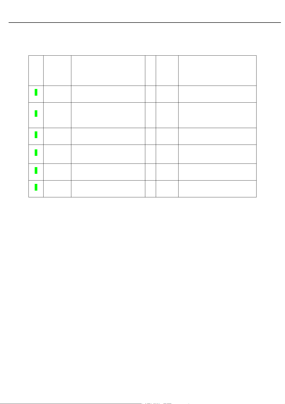
05 Spare Pare parts List
8241Q172A120H
ACER PART NO. OEM PART NO DESCRIPTION
55.LH40J.001 793111300700H PCBA,IF/B(V6,W/SPK,EMEA),LE24Q1-729
19.LH40J.001 793111400720H PCBA,P/I BOARD,W/SPK,LE24Q1-729
NA
19.LBN0J.001 791401500000R PCBA,KEYPAD BOARD,LE9D0-612 ROHS
55.LGK0J.003 792680300000H PCBA,USB BOARD,LE24Q2
40
Page 46
Acer Acer –LCD-B243HL
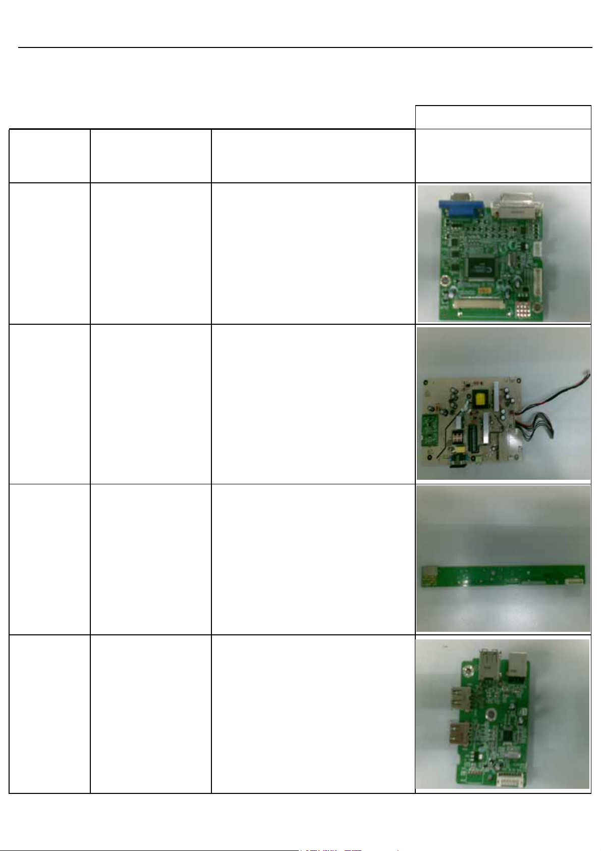
50.L63VF.003 453030300120R CABLE AUDIO 1P 6FT BLACK/GREEN CP03B06P0
50.LA10J.003 453030300370R CABLE,DVI-D 18+1P MALE 6FT BLACK , ROHS
50.LBQ0J.001 453010100380R CABLE,D-SUB 15P MALE 6FT BLACK/BLUE, ROH
50.D030J.001 453030300360R CABLE,USB 6FT BLACK ,
50.LGK0J.001 430303002440H HRN LVDS FFC 30P 166.5MM W/ALUMINUM FO
50.LGK0J.002 430300802940H HRN ASSY 2x4P to 8P 275mm UL3302#28 Con
50.LBP0J.001 430300801800R HRN ASSY 2x4P 75mm UL1571#28,ROHS
60.LH40J.001 714030030100R ASSY,BEZEL,FRONT,B,PRINTING,LE24Q1
41
Page 47
Acer Acer –LCD-B243HL
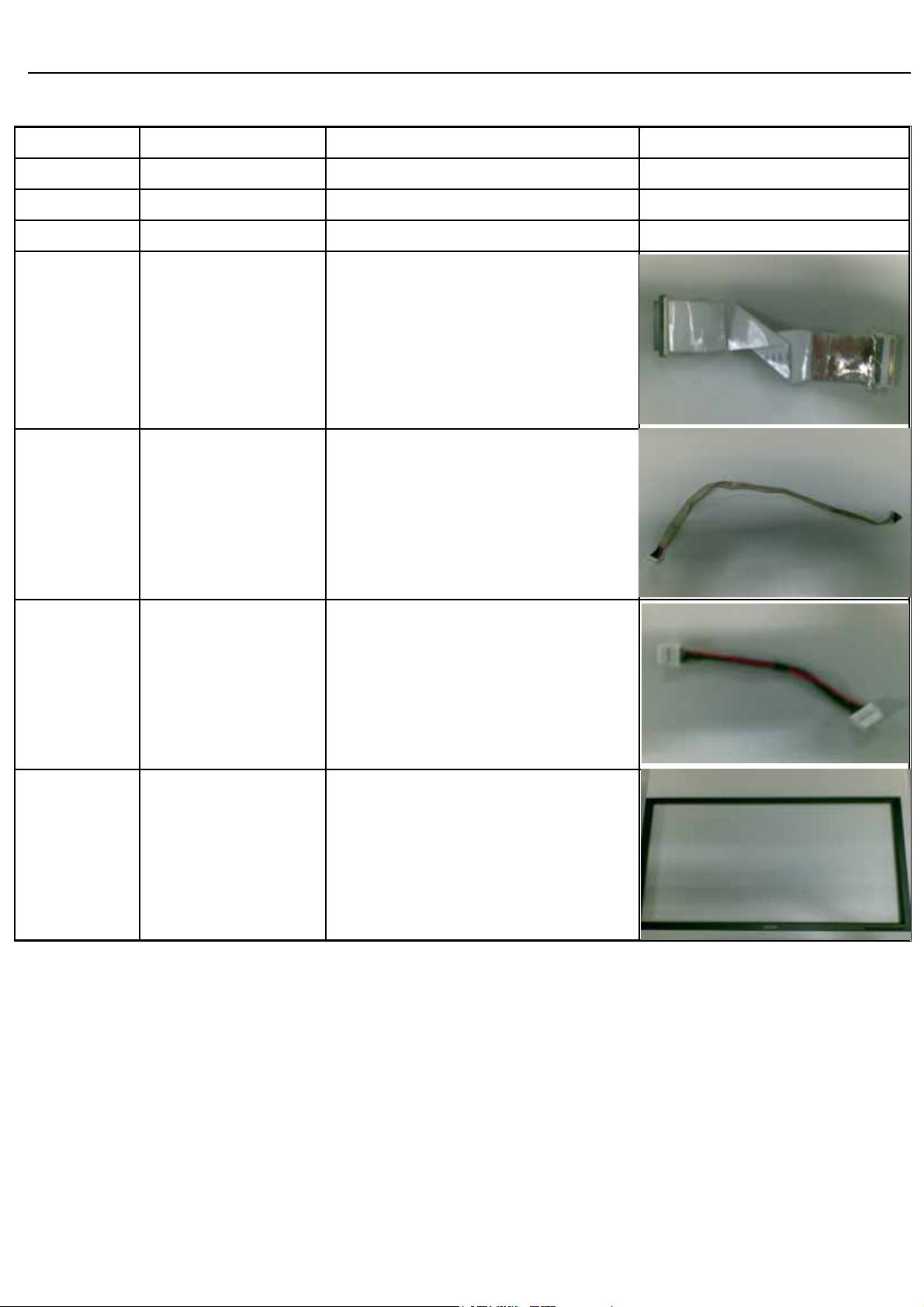
60.LDP0J.006 501020220030R COVER HINGE,BLACK ,RIGHT,FOR ADJUST,LE19D
60.LDP0J.005 501020220031R COVER HINGE,BLACK ,LEFT,FOR ADJUST,LE19D
60.LH40J.002 501020236213R BACK COVER,B,AUO THIN LED,W/DVI+VGA+USB,
60.LH40J.003 501260214700R STAND,B,,LE24Q1
60.LH40J.004 701000018213R ASSY,CHASSIS,B,AUO THIN LED,W/DVI+VGA+US
LK.24005.016 631102240320HA LCP 24"M240HW01-V6-00(A)(AUO)HF
42
Page 48
Acer Acer –LCD-B243HL
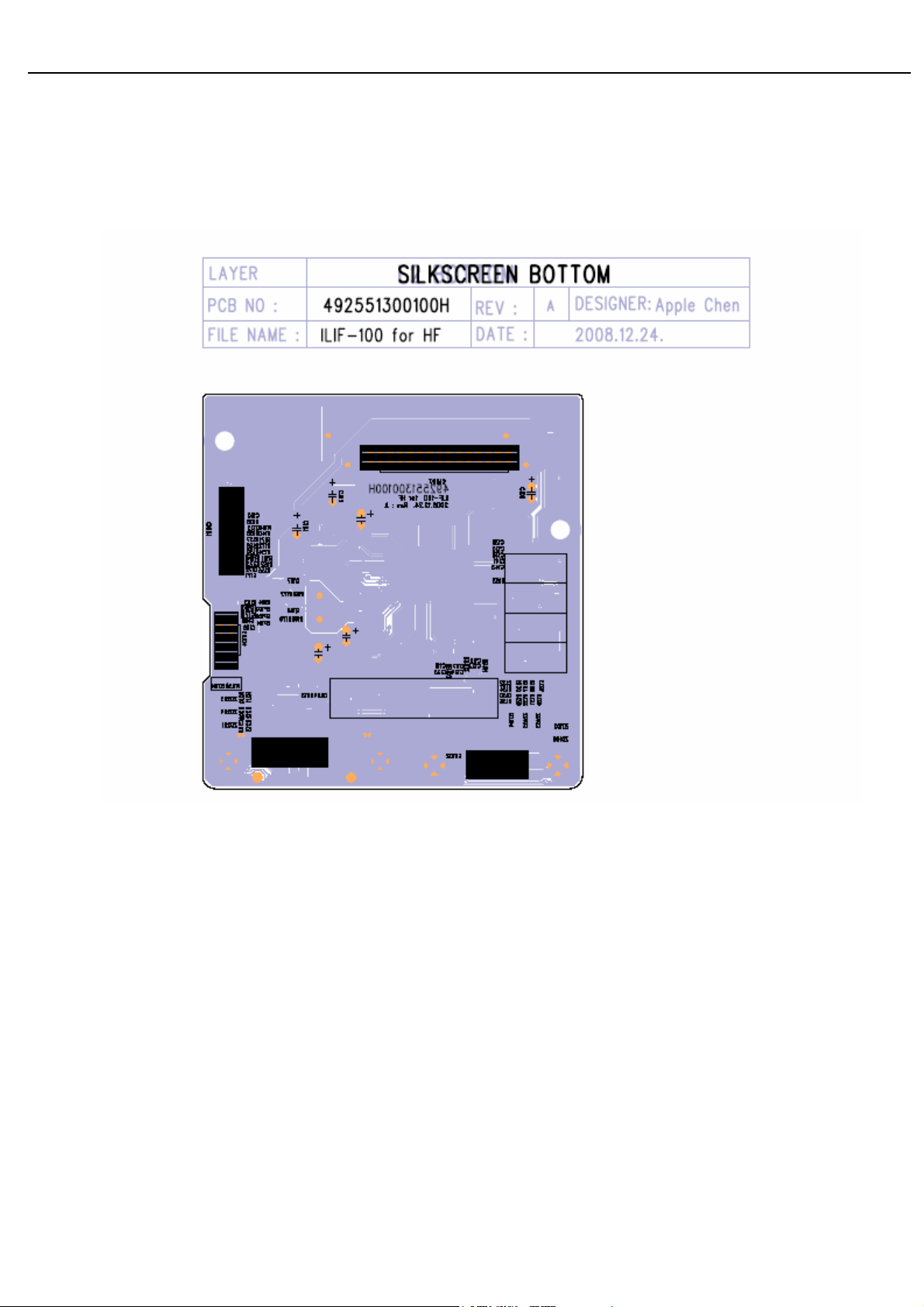
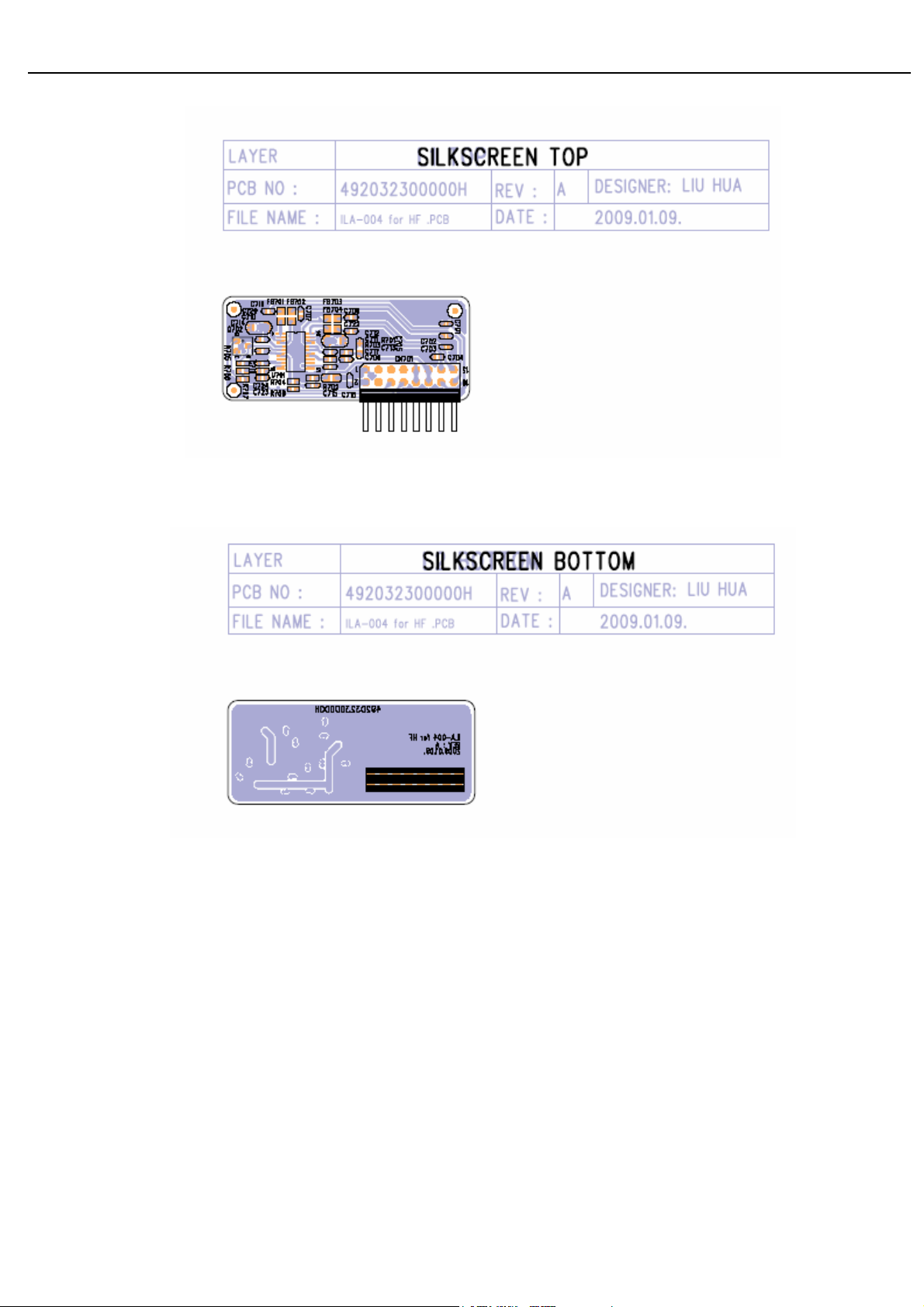
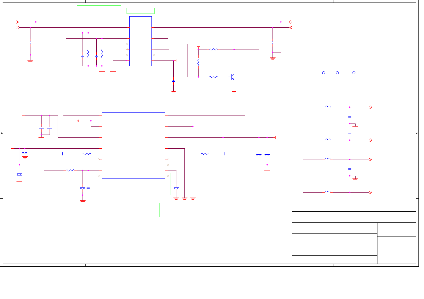
06 Schematics and Layouts
6.1 IF BD Layout
43
Page 49
Acer Acer –LCD-B243HL
I/F BD Layout
44
Page 50
Acer Acer –LCD-B243HL
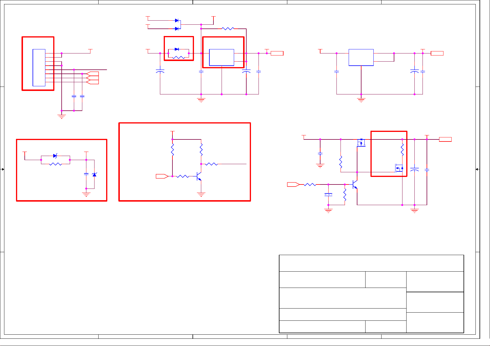
6.2 Switching Mode Power Supply circuit
45
Page 51
5
4
3
2
1
D107
BAT750-LF/NC
DVI5V
Note 1
D D
CN101
8P 2.0mm
1
2
3
4
5
6
7
8
CON--JWT-A2008WV08P-1
VCC5V
CCFL_ON/OFF
BRIGHTNESS 6
VOLUME 6
MUTE 6
C101
100u/16V
1
2
Note 2
D101
SSM24APT/NC
DIO--SMA
R101
0
+
R0805
3
C104
0.1/16V
VCC4.5VVGA5V
Note 3
U101
AP1084K33LA
3
VIN
R173 0/NC
R0805
2
VOUT
4
PAD
ADJ
1
C102
100u/16V
U102
LD1117AL-1.8V
3
+3.3V 6
+
C105
0.1/16V
C106
0.1/16V
VIN
VOUT
PAD
ADJ
1
2
4
C103
22u/16V
+1.8VVCC5V +3.3V+3.3V
+1.8V 6
+
C107
0.1/16V
To Power/Inverter
Board
C C
Note 4
VCC5V VCC_ESD
ZD101
6V2/NC
R113
0
R0805
GND
C162 0.1/16V
C111
0.1/16V
C175 0.1/16V
GND
ZD107 6V2/NC
Note 5
+3.3V
R102
10K
CCFL_ENABLE6
R106
100K
GND GND
R103
1
10K
32
PMBT3904
GND
R105
4K7
Q103
CCFL_ON/OFF
PANEL_ENABLE6
C108
0.1/16V
R107
100K
GND
C112
1u/16V
R109
100K
R108
47K
Q101
AP2305GN
1
1
32
Q104
PMBT3904
Note 6
32
R112
51/NC
R0603
1
Q102
2N7002/NC
VLCDVCC5V
VLCD 6
32
+
C110 0.1/16V
C109 100u/16V
B B
GNDGND
Note:
1. CN101 is no locked packgae for normal model.CN101 is locked packgae for special model(Dell).
2. D101 must be co-layed with R101
3. U101 must contain TO263, TO252 and SOT223 package
4. ZD101 must be co-layed with R113. ZD101 is used for ESD back drive.Reserved C111 for EMI issue.
5. P/I Board High Enable.
Document Number : SIZE :
6. Reserved R111,R112,Q102 for panel power discharge.
A A
TITLE :
DATE :
InnoLux
COMMON
POWER (DC TO DC)
2008-1-30
SHEET OF
5
4
3
2
MSTAR_TSUMU5PEHJ
A4
63
Rev :
V01
APPRO BY :
CHECK BY :
DRAWN BY :
STONE
1
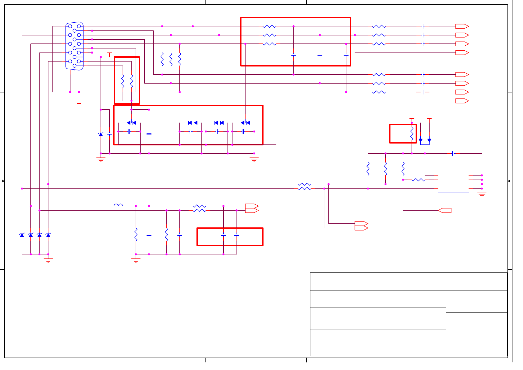
Page 52
5
4
3
2
1
1
0.1/16V/NC
Note 2
3
2
C125
RB101 0
R0603
RB102 0
R0603
RB103 0
R0603
D105
BAV99
1
VCC_ESD
GND
HSYNC 6
VSYNC 6
C116
10p/50V/NC
C117
10p/50V/NC
R131 100
R132 100
C118
10p/50V/NC
R114 75 1%
R115 75 1%
R116 75 1%
R122 75 1%
R123 75 1%
R124 75 1%
R127
R128
4K7
4K7
Note 4
R129
10K
C113 0.047u/16V
C114 0.047u/16V
C115 0.047u/16V
C119 0.047u/16V
C120 0.047u/16V
C121 0.047u/16V
VGA_DET
VCC5V
R126
0/NC
R130
1K
2
VGA5V
1
3
8
7
6
D106
BAV70
U103
AT24C02BN
VCC
WP
SCL
RED+ 6
GREEN+ 6
BLUE+ 6
SOG 6
RED- 6
GREEN- 6
BLUE- 6
VGA_DET 6
C128
0.1/16V
1
A0
2
A1
3
A2
45
GNDSDA
WP_EDID 5,6
GND
CN102
DZ11AA1-H5W6-4F
11
12
13
D D
C C
14
15
VGA_SCL
VGA_SDA
1
6
2
7
3
8
4
9
5
10
17
16
GND
ZD102 6V2
GND
VGA5V
C126 0.1/16V
R
G
B
Note 1
Note 3
FB101
120Ω
R120 0/NC
R121 0
D102
3
BAV99
2
C122
0.1/16V/NC
75 1%
75 1%
R117
R118 75 1%
R119
VGA_DET
D103
3
BAV99
1
1
C127
0.1/16V
2
C123
0.1/16V/NC
R133 1K
R134 1K
D104
3
BAV99
2
C124
0.1/16V/NC
DDC_SCL_VGA 6
DDC_SDA_VGA 6
VGA-INPUT
2008-1-30
2
MSTAR_TSUMU5PEHJ
A4COMMON
STONE
64
Rev :
V01
APPRO BY :
CHECK BY :
DRAWN BY :
1
C130 33p/50V
Note 5
C131
33p/50V/NC
C132
33p/50V/NC
InnoLux
Document Number : SIZE :
B B
ZD103 6V2
ZD104 6V2
ZD105 6V2
ZD106 6V2
GND
R135 2K2
GND
C129 33p/50V
R136 2K2
Note:
1. R120 is reserved for Samsung model.
2. R0603 package for Bead. C116,C117,C118 are reserved for EMI or performance issue.
3. C122,C123,C124,C125 are reserved for ESD or EMI issue.
4. R126 is reserved for Samsung model.
A A
5. C131,C132 are reserved for tuning performance issue.
TITLE :
DATE :
SHEET OF
5
4
3
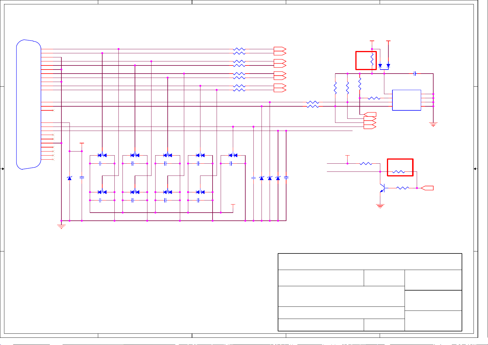
Page 53
5
CN201
DVI-D_CON
D D
C C
RX2-
RX2+
GND
RX1-
RX1+
GND
RX0-
RX0+
GND
RXC+
RXC-
SCL
SDA
VS
5V
GND
HP
RX4-
RX4+
GND
RX3-
RX3+
RX5-
RX5+
1
2
3
9
10
19
17
18
22
23
24
6
7
8
14
15
16
4
5
11
12
13
20
21
DVI_RX2DVI_RX2+
DVI_RX1DVI_RX1+
DVI_RX0DVI_RX0+
DVI_RXC+
DVI_RXC-
DVI_SCL
DVI_SDA
DVI_DET
HPD_DVI
DVI5V
ZD201 6V2
C202 0.1/16V
2
C203
0.1/16V
2
D202
3
BAV99
D203
3
BAV99
2
1
0.1/16V
2
1
C205
D204
3
BAV99
D205
3
BAV99
4
D206
3
2
C207
0.1/16V
2
BAV99
D207
3
BAV99
1
1
1
1
2
C209
0.1/16V
2
D208
3
BAV99
D209
3
BAV99
1
1
3
R201 10
R202 10
R203 10
R204 10
R205 10
R206 10
R207 10
R208 10
D210
3
BAV99
2
C211
0.1/16V
2
VCC5V
4K7
DVI5V
Note 1
R215
0/NC
R213
10K
R214
1K
R217 10K
Q201
PMBT3904
RX2- 6
RX2+ 6
RX1- 6
RX1+ 6
RX0- 6
RX0+ 6
RXC+ 6
RXC- 6
R209 100
R210 100
1
C212 0.1/16V
ZD203 6V2
ZD204 6V2
ZD202 6V2
C213 0.1/16V
R211
4K7
DVI5V
HPD_DVI
R212
DVI_DET
HPD_DVI
DVI5V
2
1
D201
BAV70
3
U201
AT24C02BN
8
VCC
7
WP
6
SCL
WP_EDID 4,6
DDC_SCL_DVI 6
DDC_SDA_DVI 6
DVI_DET 6
Note 2
R218
100/NC
32
R219
4K7
1
C201
0.1/16V
1
1
A0
2
A1
3
A2
45
GNDSDA
GND
HPD_CTRL 6
C204
B B
GND
0.1/16V
C206
0.1/16V
C208
0.1/16V
C210
0.1/16V
VCC_ESD
InnoLux
MSTAR_TSUM5PEHJ
HDCP Function
GND
Note:
1. R215 is reserved for Samsung model.
2. R218 is reserved for some model.
A A
5
4
3
Document Number : SIZE :
TITLE :
DVI-INPUT
DATE :
SHEET OF
2008-1-30
65
2
Rev :
A4COMMON
V01
APPRO BY :
CHECK BY :
DRAWN BY :
STONE
1
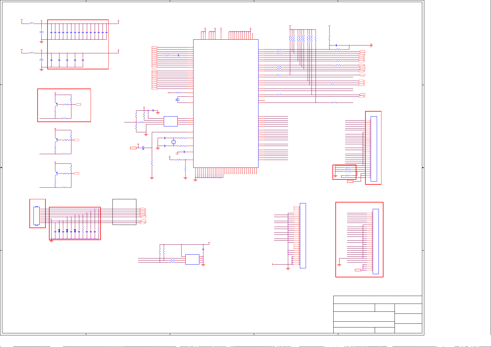
Page 54
5
VDDP_33
60Ω
C150
22u/16V
C142
22u/16V
CN104
2x4P 2.0mm
CON--CLX-CI0108P1VDL-1
To Keypad
Board
VDDC_18
Note 2
+
GND
+
GND
PMBT3906/NC
LED_B
LED_A
LED_G
1
2
3
4
5
6
7
8
Note 1
R163
330/NC
R0603
PMBT3906
R165
330
R0603
PMBT3906
R168
330
R0603
Q106
Q107
Q108
Note 3
GND
C154 0.1/16V
C159 0.1/16V
C134 0.1/16V
C135 0.1/16V
C133 0.1/16V
C143
0.1/16V
VCC5V
VCC5V
VCC5V
C155 0.1/16V
C156 0.1/16V
C144
0.1/16V
2
1
R162
3
10K/NC
R164
2
1
R166
3
10K
R167
2
1
R169
3
10K
R170
100/NC
R0603
C167 0.1/16V
C168 0.1/16V
EP101 5P35V/NC
C136 0.1/16V
C160 0.1/16V
C145
0.1/16V
0R0603
100/NCR0603
EP102 5P35V/NC
C137 0.1/16V
C146
C147
0.1/16V
0.1/16V
R161
10K
LED_B_C
R177
10K
LED_A_C
R176
10K
LED_G_C
C170 0.1/16V
C169 0.1/16V
R193 0/NC
C171 0.1/16V
EP103 5P35V/NC
C138 0.1/16V
C172 0.1/16V
C149 0.1/16V
C139 0.1/16V
PLUS-MINUS
R194 0/NC
C173 0.1/16V
C141 0.1/16V
C161 0.1/16V
+3.3V
FB102
D D
C C
B B
+1.8V
FB105
60Ω
Note4
4
AVDD_33
AVDD_18
R189
10K/NC
WP_FW
R192
10K
VCC4.5V
3
Define for X203H
MENU
RIGHT/LEFT
AUTO
E-color
LED_A
LED_G
POWER
DDC_SDA_VGA4
DDC_SCL_VGA4
DDC_SDA_DVI5
DDC_SCL_DVI5
R190
10K
R191
1K
VCC4.5V
C164 1u/16V
SCL_OSD
SDA_OSD
+3.3V
GREEN+4
GREEN-4
BLUE+4
BLUE-4
HSYNC4
VSYNC4
GND
RED+4
RED-4
SOG4
RX2+5
RX2-5
RX1+5
RX1-5
Rx0+5
RX0-5
RXC+5
RXC-5
KEY1
ADC_KEY1
ADC_KEY2
LED_B
LED_A
LED_G
KEY2
C165
0.1/16V
R175 100K
R138
4K7
R159 470
AVDD_33
GND
8
7
3
4 5
C157 22p/50V
14.31818MHz
C158 22p/50V
C152 0.047u/16V
R144
U108
SO
VCC
CS#
HOLD#
WP#
SCK
GND SI
PM25LV010A-100SCE
R147 0
X101
R148 0
VDDP_33
R149 10K/NC
R137
4K7
WP_OSD
R142 100
R143 100
390 1%
C148
1u/16V
SDO
2
SCZ
1
SCK
6
SDI
C153 0.1/16V
R180 10K
U106
8
7
6
AT24C16AN
28
27
25
24
26
23
22
32
33
34
35
9
10
12
13
15
16
18
19
5
6
7
31
30
41
42
43
44
108
128
127
102
VCC
WP
SCL
AVDD_33
8
14
20
RIN0P
AVDD_33
AVDD_33
AVDD_33
RIN0M
GIN0P
GIN0M
SOGIN0
BIN0P
BIN0M
HSYNC0
VSYNC0
DDCA_SDA/RS232_TX
DDCA_SCL/RS232_RX
RX2P
RX2N
RX1P
RX1N
RX0P
RX0N
RXCKP
RXCKN
DDCD_SDA
DDCD_SCL
REXT
REFP
REFM
SDO
CSZ
SCK
SDI
RST
XIN
XOUT
BYPASS
MODE
GND
GND
GND
GND
GND
GND
1
11
172952
7288101
GND
C140
0.1/16V
1
A0
2
A1
3
A2
45
GNDSDA
GND
3
VDDC_18
AVDD_18
104
53
74
126
21
VDDC
VDDC
VDDC
VDDC
AVDD_18
GPIO_P13/PWM2/GPIO_P26/PWM2
TSUMU58EHJ-LF-1
GND
GND
+3.3V
GND
GND
GND
106
105
686963
LVA4M/GPO[6]
LVA4P/GPO[7]
GND
GND
GND
GND
76
75
113565557616470
62
VDDP_33
8737103
112
107
40
59
114
606566
54
58
VDDP
VDDP
GPIO_P00/SAR0/GPIO_P17/SAR0
GPIO_P01/SAR1/GPIO_P00/SAR1
GPIO_P02/SAR2/GPIO_P01/SAR2
GPIO_P03/SAR3/GPIO_P02/SAR3
GPIO_P22/PWM1/GPIO_P23/PWM1
GPIO_P24/PWM2/GPIO_P27/PWM2
LVB4M/NC
LVB4P/NC
90
89
71
VDDP
VDDP
VDDP
VDDP
VDDP
VDDP
VDDP
VDDP
VDDP
VDDP
GPIO_P06
GPIO_P07
GPIO_P14/PWM0
GPIO_P15
GPIO_P16
GPIO_P44/GPIO_P41
GPIO42/GPIO_P24
GPIO_P04/GPIO_P03/PWM3
GPIO_P25/GPIO_P12/PWM3
I2C_MCL/GPIO_P10
I2C_MDA/GPIO_P11
GPIO_P43/GPIO_P42
GPIO_P45/GPIO_P04
GPIO_P46/GPIO_P05
GPIO_P47/GPIO_P22
LVB0M
LVB0P
LVB1M
LVB1P
LVB2M
LVB2P
LVBCKM
LVBCKP
LVB3M
LVB3P
LVA0M
LVA0P
LVA1M
LVA1P
LVA2M
LVA2P
LVACKM
LVACKP
LVA3M
LVA3P
NC/GPIO_P25
NC/GPIO_P43
NC/GPO[2]
NC/GPO[4]
NC/GPO[0]NCNCNCNC
116
115
111
110
67
VCTRL
117
2
+3.3V
R172 10K
R139 10K/NC
R151
R184 10K
R152 10K
R174 10K
RXO0RXO0+
RXO1RXO1+
RXO2RXO2+
RXOCRXOC+
RXO3RXO3+
R150 10K
GND
VCC5V_DET
119
R154 1K
120
R155 1K
121
122
123
124
2
3
R125 1K
4
R160 1K
36
48
R153 1K
50
51
73
109
125
39
38
R216 1K
49
47
46
45
RXO0-
100
RXO0+
99
RXO1-
98
RXO1+
97
RXO2-
96
RXO2+
95
RXOC-
94
RXOC+
93
RXO3-
92
RXO3+
91
RXE0-
86
RXE0+
85
RXE1-
84
RXE1+
83
RXE2-
82
RXE2+
81
RXEC-
80
RXEC+
79
RXE3-
78
RXE3+
77
NC
NCNCNC
118
VLCD
R171 10K
CN105
FFC-CON/NC
30
29
28
27
26
25
24
23
22
21
20
19
18
17
16
15
14
13
12
11
10
9
8
7
6
5
4
3
2
1
CON--PI-AL230C
R140 10K
FOR SINGLE LVDS INPUT
VCC5V
C166 0.1/16V/NC
R220 10K
R181 10K/NC
R179 10K
R182 20K/NC
R157 100
R158 100
WP_FW
R188
4K7
SCL_OSD
SDA_OSD
Note5
GND
GND
WP_OSD
RL111 0/NC
RL112 0/NC
RL113 0/NC
RL114 0/NC
VLCD3
VLCD3
RXO0RXO0+
RXO1RXO1+
RXO2RXO2+
RXOCRXOC+
RXO3RXO3+
RXE0RXE0+
RXE1RXE1+
RXE2RXE2+
RXECRXEC+
RXE3RXE3+
R0603
RXO0RXO0+
RXO1RXO1+
RXO2RXO2+
RXOCRXOC+
RXO3RXO3+
RXE0RXE0+
RXE1RXE1+
RXE2RXE2+
RXECRXEC+
RXE3RXE3+
LPIN6
LPIN5
LPIN6
LPIN5
CON--HR-200PHD2X15ST
R146 1K
GND
ADC_KEY1
ADC_KEY2
LED_B_C
LED_A_C
LED_G_C
VOLUME 3
MUTE 3
KEY2
VGA_DET 4
HPD_CTRL 5
KEY1
PANEL_ENABLE 3
CCFL_ENABLE 3
BRIGHTNESS 3
DVI_DET 5
WP_EDID 4,5
Note6
CN103
FFC-CON
30
29
28
27
26
25
24
23
22
21
20
19
18
17
16
15
14
13
12
11
10
9
8
7
6
5
4
3
2
1
CON--PI-AL230C
CN107
FFC-CON/NC
30
29
28
27
26
25
24
23
22
21
20
19
18
17
16
15
14
13
12
11
10
9
8
7
6
5
4
3
2
1
1
A A
Note:
1. Each bypass capacitor (0.1u/16V) must be respectively closed to pin that is DC power input of scaler IC.
2. LED blue dr iving circuit is reserved for BenQ model.
3. Bypass capacitor C167,C168,C169,C170,C171,C172,C173 are for ESD and EMI issue. ESD component
EP101,EP102,EP103 are for GPIO direct driving LED. Reserved R193&R194 for Dell 18.5W
4. CN104 is no locked packgae for normal model.CN104 is locked packgae for special model(Dell).
5. RL111,RL112,RL113,RL114 are reserved for some panel spec.
6. CN103 is no locked packgae for normal model.CN103 is locked packgae for special model(Dell).
5
InnoLux
Document Number : SIZE :
TITLE :
DATE :
4
3
2
SHEET OF
SCALER
2008-1-30
MSTAR_TSUM5PEHJ
CustomCOMMON
Rev :
66
V01
1
APPRO BY :
CHECK BY :
DRAWN BY :
Page 55
5
D D
4
3
2
1
32
DP
DM
Q302
PMBT3904
EP301ESD
5V_USB
U301
Q301
LD1117AL-3.3V
AP2305GN
312
32
VOUT
VIN
ADJ
1
C304 0.1/16V
C305 0.1/16V
R316 0
41
32
R320 0
L301
NC/20mH
EP302ESD
CN302
UC11123-LK1
56
4
12
DP
3
DM
2
VBUSPWR
1
34
CN301
8P 2.0mm 90°
5V_USB
FB303
120Ω 3A
OVRP1#
+
C324 220u/10V
R326 22K
C C
OVRP1#
OVRP1#
OVRP1#
B B
PWR1
DD1M
C325 0.1/16V
DD1P
FB304
120Ω 3A
PWR2
DD2M PWR2_USB
C326 0.1/16V
DD2P
FB305
120Ω 3A
DD3M
C327 0.1/16V
DD3P
FB306
120Ω 3A
PWR4
DD4M
C328 0.1/16V
DD4P
R336 NC/0
R337 NC/0
DD1P
41
32
L306
DD1M
NC/20mH
R338 NC/0
R325 0
41
R327 0
32
R328 0
R329 0
41
R330 0
R331 0
R332 0
R333 0
R334 0
R335 0
PWR1_CAMER A
NC/EP312ESD
NC/EP311ESD
PWR1
D1M
L302
NC/20mH
D1P
EP303ESD
EP304ESD
32
L303
NC/20mH
41
32
L304
NC/20mH
41
32
L305
NC/20mH
D1P0
D1M0
D2M
D2P
GND
EP306ESD
EP305ESD
EP308ESD
EP307ESD
EP310ESD
EP309ESD
Note:change D1P0 to pin2
change D1M0 to pin3
Date:2008/09/01
PWR1_CAMER A
D1P0
D1M0
CN303
1
VCC1
2
DD1-
3
DD1+
4
GND1
5
VCC2
6
DD2-
7
DD2+
8
GND2
9
SHELL
PWR3
CN304
D3M
UB111234K5
D3P
4321
GND
6 5
PWR4_USB
D4M
D4P
4321
GND
6 5
CN306
1
2
3
4
5
5P 2.0mm 90° /NC
To Camera Module.
CN305
UB111234K5
+5V_USB
+
R301
C301
100u/16V
4K7
+5V_USB
R311 10K
1
Delete R315;R317
for Acer X233H
Date: 08/09/01
Tomxiao
R313 10K
NC/R315 0
NC/R317 0
1
2
3
4
VBUSPWR
5
6
7
8
10p/50V
30.000MHz
C321
3.3V_USB
+
C302
C3030.1/16V
10u/25V
DP0
DM0
3.3V_USB
R302 0/NC
R304 0/NC
R306 0
R308 0
R31010K
VBUSPWR
3.3V_USB
R3190
R3180
R3220/NC
R3210/NC
R323 0
VDD25OUT
X301
C322
10p/50V
C306
1u/16V
VDD25OUT
VSSREG
AVDD33
R312
15K
U302
1
VDD25OUT
2
VSSREG
3
LED4
4
LED3
5
LED2
6
LED1
7
GREEN
8
AMBER
9
VDD33
X1
10
X1
X2
11
X2
12
VDD25
3.3V_USB
C323
0.1/16V
AVDD33
48
VBUSM
VDD33REG
BUS_B
TEST
1314151617181920212223
R303 0
R305 0
R307 0/NC
R309 0/NC
VSS
PPB2
PPB1
CSB3
CSB2
CSB1
NEC-uPD720114
HTQFP48
RREF
AVSS(R)
AVDD
AVSS
AVDD
ADD33
R3242K43 1%
AVDD
AVDD33
AVSS
C307
1u/16V
VDD25OUT
DD3P
DD3M
DD4P
DD4M
AVDD33
DD2P
DD2M
DD1P
DD1M
3.3V_USB
R31410K
AVDD33
VSSREG
AVDD
AVSS
C308
4.7u/10V
C314
0.1/16V
VDD25OUT
22u/16V
C309
0.1/16V
C315
4.7u/10V
C317
3.3V_USB
C311
C310
C312
0.1/16V
0.1/16V
0.1/16V
FB30160Ω
VDD25OUT
C313
C316
0.1/16V
4.7u/10V
FB30260Ω
+
C319
C320
C318
0.1/16V
0.1/16V
0.1/16V
OVRP1#
3738394041424344454647
PPB4
PPB3
CSB4
SYSRSTB
36
VSS
35
DP4
34
DM4
33
VDD25
32
DP3
31
DM3
30
VDD33
29
DP2
28
DM2
27
VSS
26
DP1
25
DM1
DMU
DPU
VSS
VDD25
24
VDD25OUT
DP0
DM0
A A
InnoLux
USB HUB
2008-09-01
1
X233H
11
Document Number : SIZE :
TITLE :
DATE :
5
4
3
2
SHEET OF
APPRO BY :
A1
CHECK BY :
DRAWN BY :
Rev :
V01
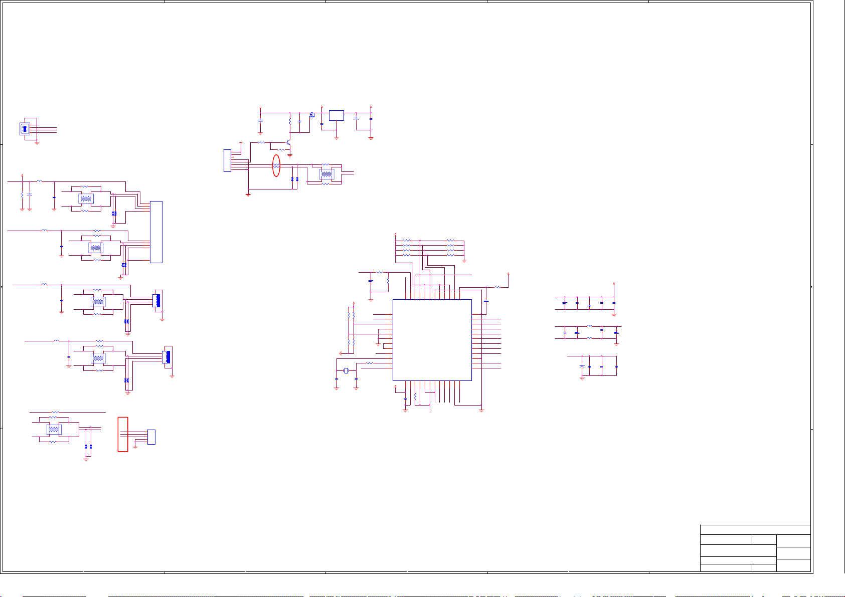
Page 56
5
change for FHD2102
ID from 90 degree to
180 degree
ROUT-
ROUT+ LOUT+
D D
C703 100p/50V
C704 100p/50V
AR_IN
AL_IN
C705 1500p/50V
R701 10K
C706 1500p/50V
R702 10K
R_OUT-
R_OUT+
GND
4
CN701
2*8P 2.54mm 180°
15
ROUT-
13
ROUT+
9
AL
7
EO_R
5
EO_L
3
Hp/Sp
1
GND
LOUT-
LOUT+
ARAR
SHUT
VOL
AGND
+5V
Power Board
16
14
1211
10
AL
8
6
4
2
L_OUT-
L_OUT+
AR
AL
MUTE
VOL
Audio5V
C718 0.1/16V
+5V
3
+5V
R705 10K
R70615K
R707 15K
2
LOUT-
MUTE_IC
32
Q702
PMBT3904
1
C701 100p/50V
C702 100p/50V
Mark
Z1
Z2
Mark
Z3
Mark
1
C C
ROUT_P
ROUT_NLOUT_N
AR_IN
C711 1u/16V
+5V
C712 10u/25V
C710 1u/16V
C715 0.47/16V
LOUT_P
MUTE_IC
R704 10K
R708 10K
C723 1u/16V
+5V
C720 10u/25V
+5V
B B
C716
1u/16V
C714
1u/16V
AL_IN
VOL
C724 0.1/16V
1
+OUT_L
2
PGNDL
4
-OUT_L
5
PVDD
7
VDD
8
INL
10
VDC
11
Volume
12
NC
U701
PAM8603M
+OUT_R
PGNDR
PGNDRPGNDL
-OUT_R
PVDD
SHDNMUTE
GND
INR
VREF
24
23
223
21
20
196
18
17
169
NCNC
15
NC
14
13
NC
C717 4.7u/10V
R703 10K
C713 0.47/16V
LOUT_P
LOUT_N
ROUT_N
ROUT_P
FB701
120Ω 3A
FB702
120Ω 3A
FB703
120Ω 3A
FB704
120Ω 3A
LOUT+
C719
470p/50V
C707
470p/50V
LOUT-
ROUT-
C708
470p/50V
C722
470p/50V
ROUT+
AC OFF PoP noise
solution change C717
form 0.1u to 4.7u
Document Number : SIZE :
A A
TITLE :
InnoLux
Audio
PAM8603M
APPRO BY :
BAUDIO COMMON BOARD
CHECK BY :
DATE :
SHEET OF
5
4
3
2
2008-10-07
22
Rev :
DRAWN BY :
V05
1
Page 57
Acer Acer –LCD-B243HL
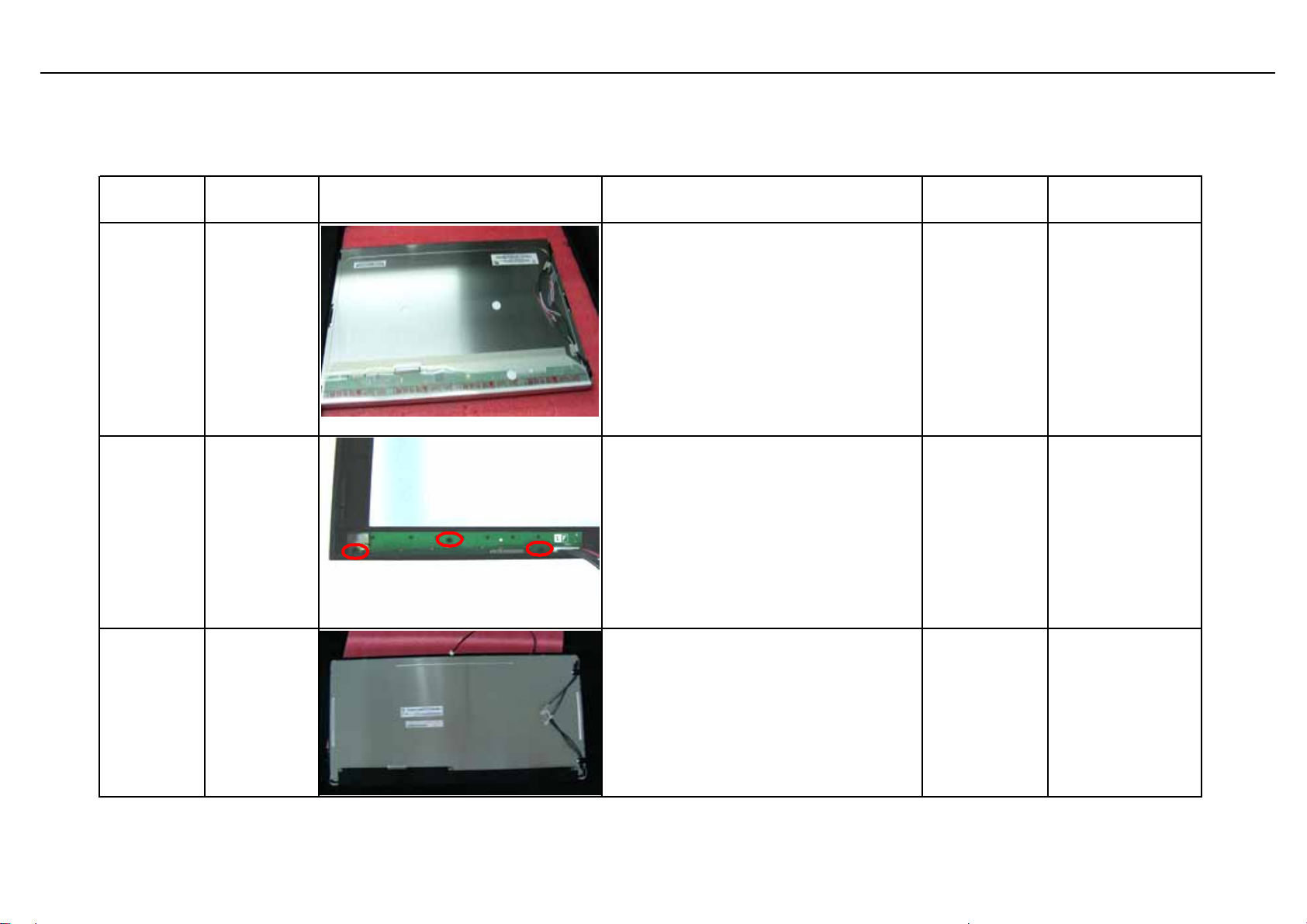
7.0 Assembly and Disassembly
The tool of Assembly and disassembly : 1) Electrostatic gloves 2) Electric screwdriver: the length of screwdriver top is 6±0.5cm and 15±0.5cm ;
the diameter of screwdriver top is Φ5*H5mm
Sequence Item Photo Procedures PN Description
1.Take panel out of box and place it
on the foam;
2.Tear open the PE bag and put it in
S1 Place panel
the designated carton;
3. Place panel on the foam like the
attached picture.
Remark: Do not touch the lamp cord
and place the surface of panel
downsides on the cushion.
631102240320HALCP 24"M240HW 01-
V6-00(A)(AUO)HF
S2
Assemble
Keypad Pad
and Bezel
Assemble the key board designated
location on the Bezel , like the
attached picture
1.Put the bezel on the form,withing it's
key board is on the right hands.
S3
Assemble
front bezel
2.Put the panel with two hands and
put into the bezel carefully , without
scratching the panel
46
791401500000R
714030030100R
PCBA,KEYPAD
BOARD,LE9D0-612
ROHS
ASSY,BEZEL,FRON
T,B,PRINTING,LE24
Q1
Page 58

Acer Acer –LCD-B243HL
C
4
6
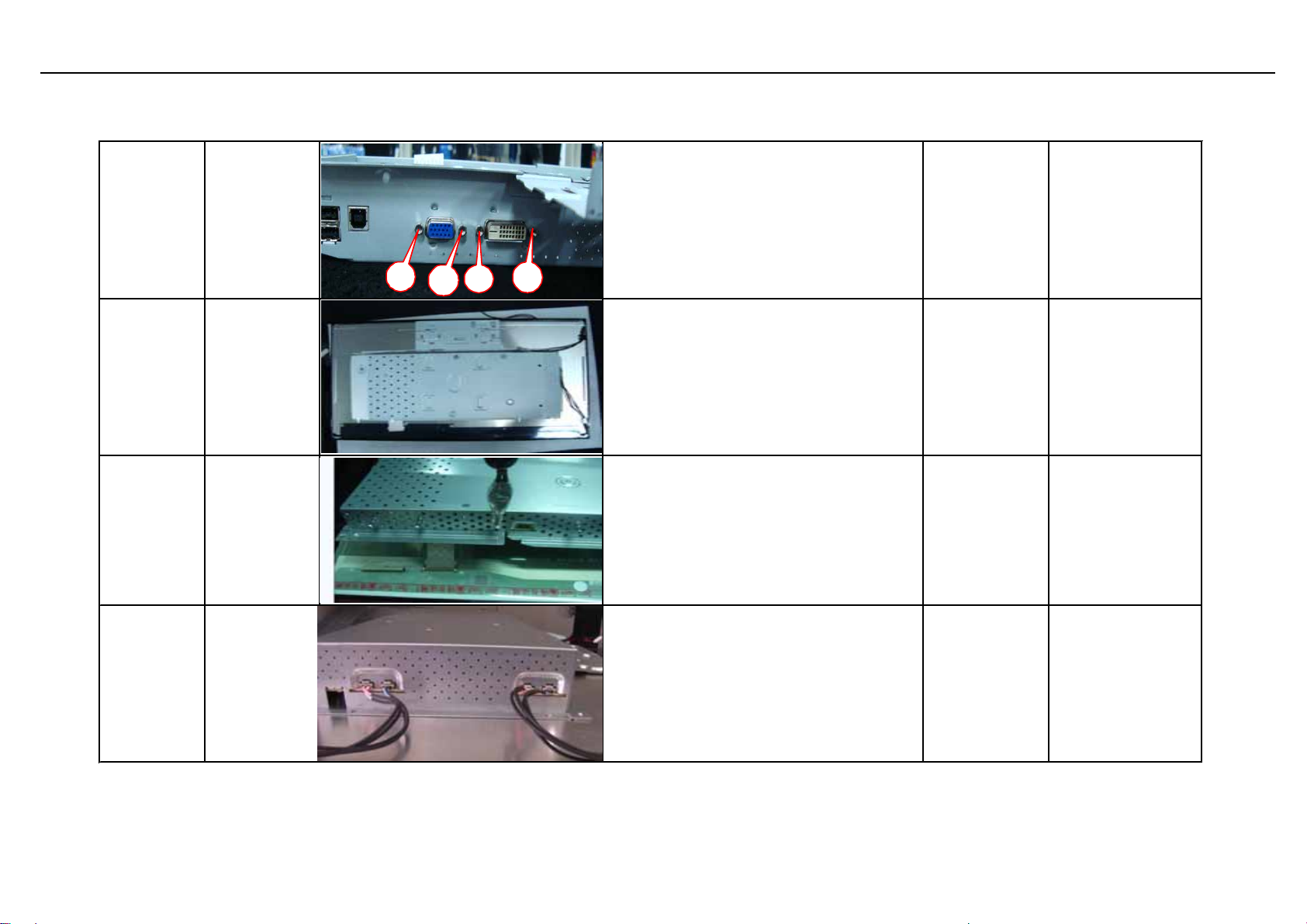
Assembly and Disassembly (continue)
Insert IPC
electric foam on
the chassis like
1.Place the chassis on the cushion
after check, like the attached picture.
2.Insert power board into the
designated location of chassis,like the
attached picture.
701000018213R
ASSY,CHASSIS,B,A
UO THIN
LED,W /DVI+VGA+U
S
S4
the attached
Assemble
chassis and
PI board
S5
S6
Insert FF
cable into
mainboard
and Connect
USB board
mainboard
and power
board
Fix USB
board
mainboard
and power
board
FFC
7
connect usb
1
boad and
P/I bord
2
5
1. Take FFC cable & main board,
check the board if OK;
2. Insert FFC cables into designated
location ;
3.connect USB board ,I/Fboard P/I
board and like the picture location
4.Check the FFC cable if OK
3
Fix USB board mainboard and power
board like the picture.
430303002440H
792680300000H
HRN LVDS FFC
30P 166.5MM
W/ALUMINUM FO
PCBA,USB
BOARD,LE24Q2
47
Page 59
Acer Acer –LCD-B243HL
Assembly and Disassembly (continue)
1. Handle hexagonal screws and
Twist
S7
S8 Fix chassis
hexagonal
screws
4
2
3
electric opener;
2. Twist screw in the interface as
attached picture;
3. Place cushion on the designated
location after iron frame is taken away.
fix chassis into bezel hook as
attached picture.
701000018213R
ASSY,CHASSIS,B,A
UO THIN
LED,W /DVI+VGA+U
S
1. Insert FFC cable into desiganted
connector and use jig to insert it;;
2. Tear off foil to stick the cable for fix.
Insert 4pcs lamp wire into the relevant
position and make sure the red one is
on the left and the blue is on the right
as attached picture.
S9
S10
Insert
FFCcable
Insert lamp
wire
48
Page 60
Acer Acer –LCD-B243HL
p
1.insert the speaker cable into the PIN
location of chassis like the attached
picture
2.be sure the red cable is on the left
and the green one is on the right.
3.be sure the cable is outside of the
eaker.
s
S11
Assemble
the speaker
Insert
S12
keypad
cable
S13
Assemble
back cover
S14 Fix stand
Insert keypad cable into designated
location as attached picture.
Buckle back cover according to the
sequence as attached picture and
check if the cover is fixed properly.
1.Place stand on the location ,tear
open the PE bag ,check if ok and take
4pcs screws to lock the stand as
attched picture
HRN ASSY 2x4P to
430300802940H
501020236213R
501260214700R STAND,B,,LE24Q1
8P 275mm
UL3302#28 Con
BACK
COVER,B,AUO THIN
LED,W/DVI+VGA+U
SB,
S15 Packing
Release monitor the packing like and
pack it like attached picture
49
 Loading...