


AT150 F1 Series
User Guide

© 2010. All Rights Reserved.
Acer AT150 F1 Series
User Guide
Acer AT150 F1
Model Number :
Serial Number:
Purchase Date:
Place of Purchase:

iii
Information for your safety and comfort
Safety instructions
Read these instructions carefully. Keep this document for future reference.
Follow all warnings and instructions marked on the product.
Turning the product off before cleaning
Unplug this product from the wall outlet before cleaning. Do not use liquid
cleaners or aerosol cleaners. Use a damp cloth for cleaning.
CAUTION for plug as disconnecting device
Observe the following guidelines when connecting and disconnecting power to
the power supply unit:
• Install the power supply unit before connecting the power cord to the AC
power outlet.
• Unplug the power cord before removing the power supply unit from the
computer.
• If the system has multiple sources of power, disconnect power from the
system by unplugging all power cords from the power supplies.
CAUTION for accessibility
Be sure that the power outlet you plug the power cord into is easily accessible
and located as close to the equipment operator as possible. When you need to
disconnect power to the equipment, be sure to unplug the power cord from the
electrical outlet.
Warnings
• Do not use this product near water.
• Do not place this product on an unstable cart, stand or table. If the product
falls, it could be seriously damaged.

iv
• Slots and openings are provided for ventilation to ensure reliable
operation of the product and to protect it from overheating. These
openings must not be blocked or covered. The openings should never be
blocked by placing the product on a bed, sofa, rug or other similar surface.
This product should never be placed near or over a radiator or heat
register, or in a built-in installation unless proper ventilation is provided.
• Never push objects of any kind into this product through cabinet slots as
they may touch dangerous voltage points or short-out parts that could
result in a fire or electric shock. Never spill liquid of any kind onto or into
the product.
• To avoid damage of internal components and to prevent battery leakage,
do not place the product on a vibrating surface.
• Never use it under sporting, exercising, or any vibrating environment
which will probably cause unexpected short current or damage rotor
devices, HDD, Optical drive, and even exposure risk from lithium battery
pack.
• This product is not suitable for use with visual display workplace devices
according to B2 of the German Ordinance for Work with Visual Display
Units.
Using electrical power
• This product should be operated from the type of power indicated on the
marking label. If you are not sure of the type of power available, consult
your dealer or local power company.
• Do not allow anything to rest on the power cord. Do not locate this
product where people will walk on the cord.
• If an extension cord is used with this product, make sure that the total
ampere rating of the equipment plugged into the extension cord does not
exceed the extension cord ampere rating. Also, make sure that the total
rating of all products plugged into the wall outlet does not exceed the fuse
rating.
• Do not overload a power outlet, strip or receptacle by plugging in too
many devices. The overall system load must not exceed 80% of the branch
circuit rating. If power strips are used, the load should not exceed 80% of
the power strip's input rating.
• This product's power supply is equipped with a three-wire grounded plug.
The plug only fits in a grounded power outlet. Make sure the power outlet
is properly grounded before inserting the power supply plug. Do not insert
the plug into a non-grounded power outlet. Contact your electrician for
details.
Warning! The grounding pin is a safety feature. Using a power outlet that is
not properly grounded may result in electric shock and/or injury.

v
Note: The grounding pin also provides good protection from unexpected
noise produced by other nearby electrical devices that may interfere with
the performance of this product.
• Use the product only with the supplied power supply cord set. If you need
to replace the power cord set, make sure that the new power cord meets
the following requirements: detachable type, UL listed/CSA certified, VDE
approved or its equivalent, 4.6 meters (15 feet) maximum length.
Product servicing
Do not attempt to service this product yourself, as opening or removing covers
may expose you to dangerous voltage points or other risks. Refer all servicing to
qualified service personnel.
Unplug this product from the wall outlet and refer servicing to qualified service
personnel when:
• the power cord or plug is damaged, cut or frayed
• liquid was spilled into the product
• the product was exposed to rain or water
• the product has been dropped or the case has been damaged
• the product exhibits a distinct change in performance, indicating a need
for service
• the product does not operate normally after following the operating
instructions
Note: Adjust only those controls that are covered by the operating
instructions, since improper adjustment of other controls may result in
damage and will often require extensive work by a qualified technician to
restore the product to normal condition.
Disposal instructions
Do not throw this electronic device into the trash when discarding.
To minimize pollution and ensure utmost protection of the global
environment, please recycle. For more information on the Waste
www.acer-group.com/public/Sustainability/sustainability01.htm.
from Electrical and Electronics Equipment (WEEE) regulations, visit

vi
Regulations and safety notices
FCC notice
This device has been tested and found to comply with the limits for a Class A
digital device pursuant to Part 15 of the FCC rules. These limits are designed to
provide reasonable protection against harmful interference in a residential
installation. This device generates, uses, and can radiate radio frequency energy
and, if not installed and used in accordance with the instructions, may cause
harmful interference to radio communications.
However, there is no guarantee that interference will not occur in a particular
installation. If this device does cause harmful interference to radio or television
reception, which can be determined by turning the device off and on, the
user is encouraged to try to correct the interference by one or more of the
following measures:
• Reorient or relocate the receiving antenna.
• Increase the separation between the device and receiver.
• Connect the device into an outlet on a circuit different from that to which
the receiver is connected.
• Consult the dealer or an experienced radio/television technician for help.
Notice: Shielded cables
All connections to other computing devices must be made using shielded cables
to maintain compliance with FCC regulations. In compliance with FCC
regulations, use shielded cables to connect to other computing devices. A duallink cable is recommended for DVI output.
Notice: Peripheral devices
Only peripherals (input/output devices, terminals, printers, etc.) certified to
comply with the Class A limits may be attached to this equipment. Operation
with non-certified peripherals is likely to result in interference to radio and TV
reception.
Caution
Changes or modifications not expressly approved by the manufacturer could
void the user's authority, which is granted by the Federal Communications
Commission, to operate this computer.

vii
Operation conditions
This device complies with Part 15 of the FCC Rules. Operation is subject to the
following two conditions: (1) this device may not cause harmful interference,
and (2) this device must accept any interference received, including interference
that may cause undesired operation.
Notice: Canadian users
This Class A digital apparatus complies with Canadian ICES-003.
Remarque à l'intention des utilisateurs canadiens
Cet appareil numérique de la classe B est conforme a la norme NMB-003 du
Canada.
Compliant with Russian regulatory certification
Notice: BSMI
Laser compliance statement
The CD or DVD drive used with this computer is a laser product.
The CD or DVD drive's classification label (shown below) is located on the drive.
CLASS 1 LASER PRODUCT
CAUTION: INVISIBLE LASER RADIATION WHEN OPEN. AVOID EXPOSURE
TO BEAM.
Appareil à laser de classe 1
Attention : Radiation laser visible et invisible en cas d’ouverture. Éviter toute
exposition aux rayons.
Laserprodukt der Klasse 1
Achtung: Beim Öffnen werden unsichtbare Laserstrahlen freigelegt. Setzen Sie
sich diesen Strahlen nicht aus.

viii
Prodotto laser di classe 1
Attenzione: Radiazioni laser invisibili in caso d’apertura. Evitare l’esposizione ai
raggi.
Producto láser de Clase 1
Precaución: Cuando está abierta, hay radiación láser. Evite una exposición al haz
de luz.
Produto Laser de Classe 1
Precaução: Radiação laser invisível quando aberto. Evite exposição ao feixe.
Laserproduct klasse 1
Voorzichtig: Onzichtbare laserstraling indien geopend. Voorkom blootstelling
aan straal.
Declaration of Conformity for EU countries
Hereby, Acer, declares that this system is in compliance with the essential
requirements and other relevant provisions of Directive 1999/5/EC.
List of applicable countries
This device must be used in strict accordance with the regulations and
constraints in the country of use. For further information, please contact local
office in the country of use. Please see http://ec.europa.eu/enterprise/rtte/
implem.htm for the latest country list.

Information for your safety and comfort iii
Regulations and safety notices vi
1 System tour 1
System notes 2
External and internal structure 3
Front panel 3
Rear panel 7
Internal components 9
Mainboard Layout 10
Mainboard jumper settings 14
2 System setup 17
Setting up the system 18
Pre-installation requirements 18
Connecting peripherals 19
Turning on the system 21
To power on the system 21
Power-on problems 22
Configuring the system OS 23
Turning off the system 24
3 System upgrades 25
Installation precautions 26
ESD precautions 26
Pre-installation instructions 27
Post-installation instructions 27
Opening the server 28
Removing and installing the side panel 28
Configuring the hard disk drive 30
Accessing the drive bays 30
Hard disk drive configuration guidelines 31
Determining the drive status 32
Configuring a 5.25-inch storage device 38
Installing an optional 5.25-inch storage device 38
Removing a 5.25-inch storage device 41
Replacing the processor and heatsink fan assembly 42
Removing and installing the heatsink fan assembly 42
Removing and installing the processor 47
Upgrading the system memory 50
System memory interface 50
Contents

x
Installing an expansion card 61
Installing a SAS card 61
4 System BIOS 65
BIOS overview 66
Entering BIOS Setup 67
BIOS setup primary menus 67
BIOS setup navigation keys 68
Main menu 69
Advanced menu 71
Processor Configuration 72
ATA Controller Configuration 75
Serial Port Configuration 79
USB Configuration 80
USB Mass Storage Device Configuration 80
PCI/PnP Configuration 81
Advanced Chipset Control 82
Power Configuration 89
Security Settings 91
Server Management 94
System Information 94
Console Redirection 96
Boot Configuration 98
Boot Setting Configuration 98
Boot Device Priority 99
Hard Disk Drives 99
Removable Drives 99
CD/DVD Drives 99
Network Drives 100
Exit Options 101
5 System troubleshooting 103
Resetting the system 104
Initial system startup problems 104
BIOS error beep codes 105
Initial troubleshooting checklist 106
Hardware diagnostic testing 107
Checking the boot-up status 107
Verifying the condition of the storage devices 108
Confirming loading of the operating system 108
Specific problems and corrective actions 109

Appendix A Server management tools 113
Server management overview 114
RAID configuration utilities 115
Intel Onboard SATA RAID Creation 115
Adaptec Onboard SATA RAID Creation 116
MegaRAID SAS 8204ELP Creation 118
MegaRAID SAS 8708EM2 RAID Creation 120
Flex IO SAS RAID Creation 122
Appendix B Rack mount configuration 125
Rack installation information 126
System rack installation 128
Vertical mounting hole pattern 129
Installing the system into the rack 130
Appendix C Acer Smart Console 137
Using Acer Smart Console 138
Software requirements 138
Accessing Acer Smart Console 139
Acer Smart Console user interface 140
System Information 140
Server Health 141
Configuration 143
Remote Control 153
Launch SOL 155
Virtual Media 156
Maintenance 158
KVM function description 159
Exit 165
xi
Index 167

xii

1 System tour

2
1 System tour
System notes
The AT150 F1 is an outstanding 4U dual socket rack-mountable tower
server that supports up to two new generations of Intel architecture
processors (Intel
technology, PCI Express Gen2 (5.0Gb/s), dual onboard gigabit Ethernet
controllers with Intel
and iSCSI boot and integrated BMC management feature.
The AT150 F1 targets small and medium businesses that require server
solution combined with performance, reliability and expandability.
AT150 F1 is a flexible and high reliability tower server that satisfies
growing businesses and customers’ needs.
System features and support
• Supports up to four 3.5-inch or eight 2.5-inch SAS/SATA hard disk
drives
• Six USB ports (four on the rear panel and two on the front panel)
• Supports dual Intel
• Twelve DIMM slots that support a maximum of 96 GB (registered)
or 48 GB (unbuffered) memory
®
Xeon 5500 / 5600 series processors), DDR3 memory
®
I/O Acceleration Technology 2 (IOAT 2), VT-d
®
Xeon 5500 / 5600 series processors
External and internal structure
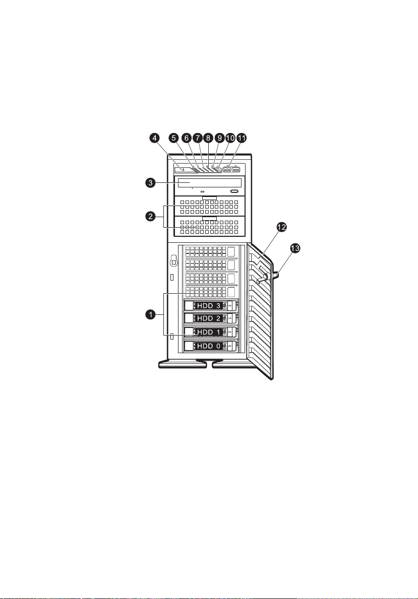
Front panel
With 3.5-inch HDD bays
3
4
1 System tour
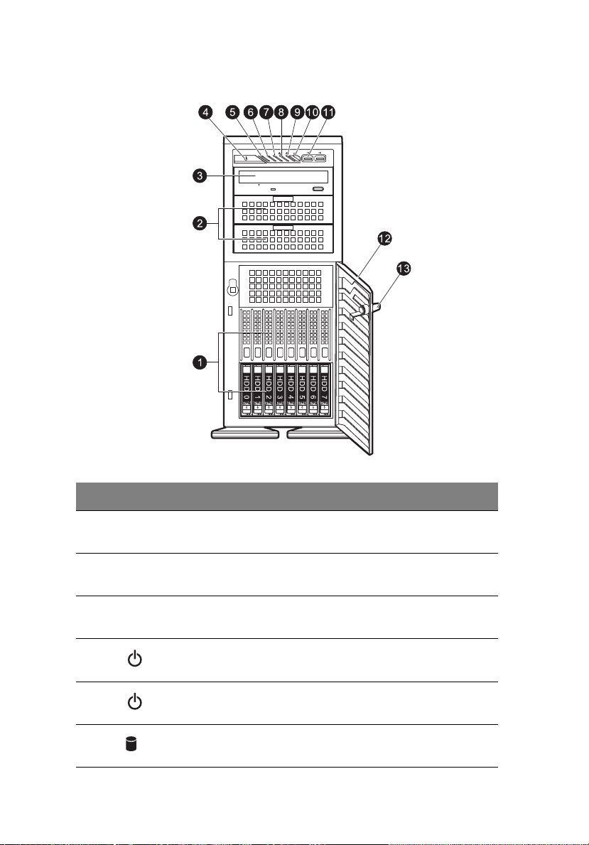
With 2.5-inch HDD bays
No. Icon Component Description
1 Hard disk drive
bays
2 5.25-inch drive
bays
3 Optical drive Disk drive for reading CD, VCD, and
4 Power button Press to turn the server on/off, or to
5 Power indicator Indicates the system power status.
6 HDD activity
indicator
Drive bays for 2.5-inch or 3.5-inch
hard disk drives.
Drive bays for 5.25-inch devices (i.e.
ODD, tape drives, etc.)
DVD contents.
put it in standby mode
Indicates the status of a system hard
disk drive.

No. Icon Component Description
5
7 System status/fault
indicator
8 LAN port 1 activity
indicator
9 LAN port 2 activity
indicator
10 System ID switch/
indicator
11 USB 2.0 ports Connect to USB devices.
12 Bezel door Unlock and open the bezel door to
13 Security keylock Secures the bezel door to protect the
Indicates the status of the system
operations.
Indicates the system network 1
connection status.
Indicates the system network 2
connection status.
Indicates if the system ID button is
pressed or activated through IPMI.
power on the server and access the
server’s hard drives and USB ports.
server unit from unauthorized access.
6
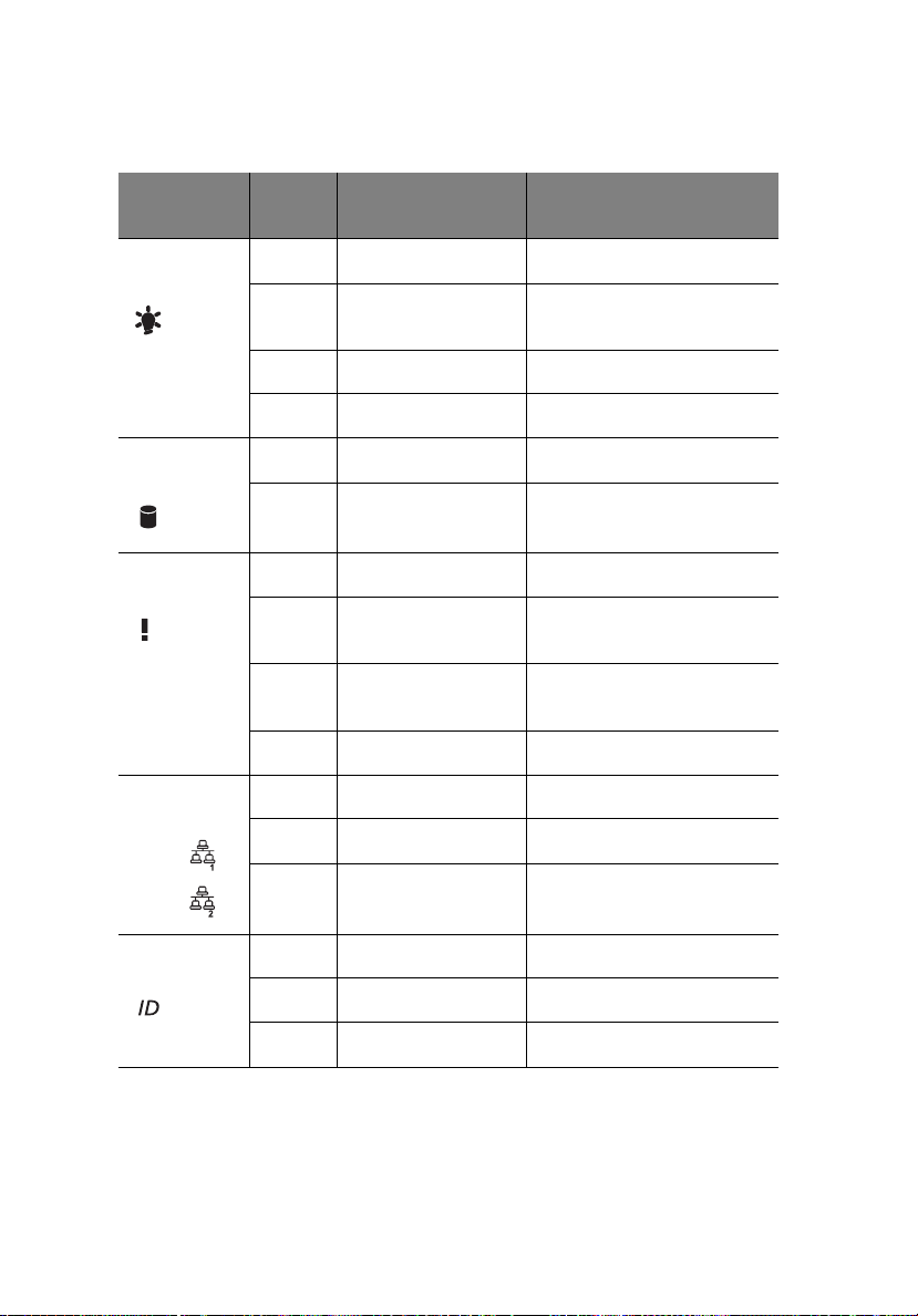
Front panel LED indicator status
1 System tour
LED
indicator
Power state
indicator
HDD activity
indicator
System
status
LAN activity
indicators
LAN1
LAN2
LED
color
Green On S0: Power On
Green Blink (1 Hz with at
N/A Off S4
N/A Off S5
Amber Blink HDD access
N/A Off No access and
Red On CPU overheat
Red Fast blink (once per
Red Slow blink (once
N/A Off Normal
Green On LAN link/No access
Green Blink LAN access
N/A Off Disconnect/Idle
LED state Status
S1: Sleep
50% duty cycle)
No HDD fault
Fan failure
second)
Power failure
every 4 seconds)
System ID
indicator
N/A Off Normal
Blue On System Identification
Blue Blinking IPMI-activated system ID
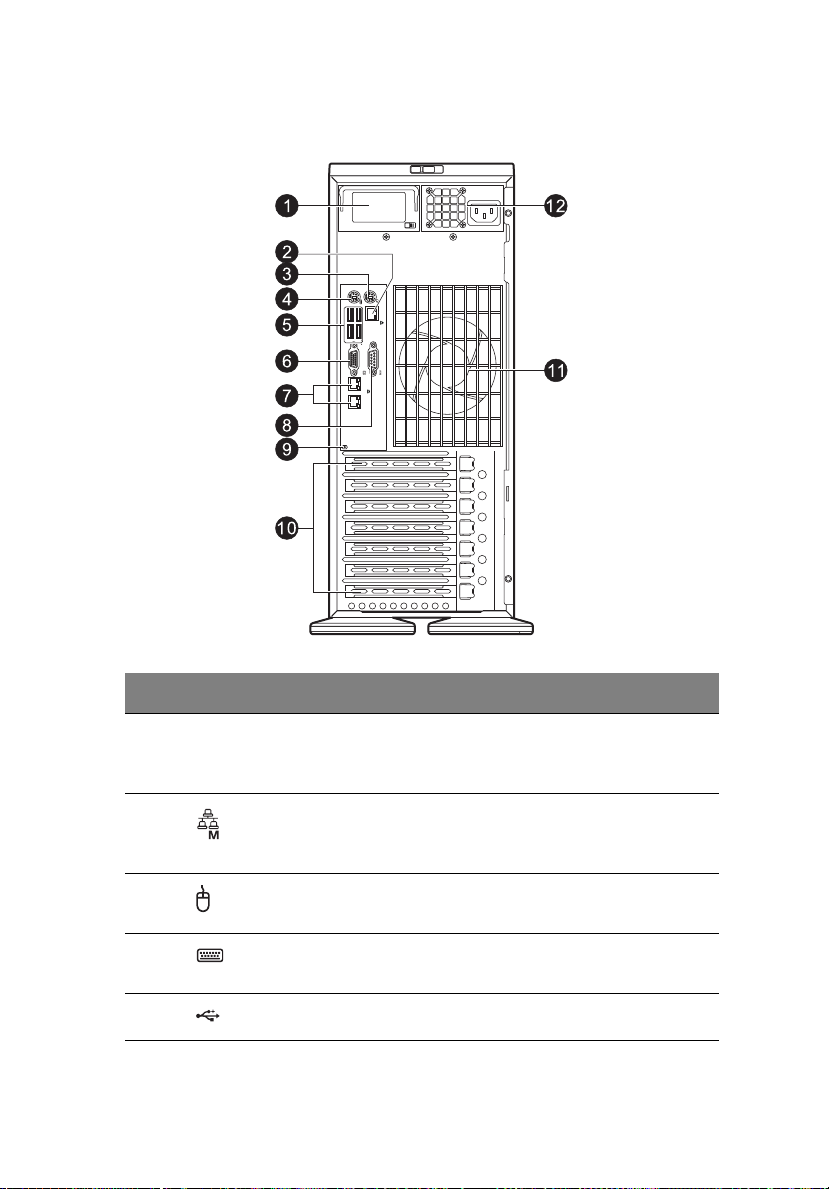
Rear panel
7
No. Icon Component Description
1Dummy
power supply
module
2Server
management
port (10/100)
3 PS/2 mouse
port
4 PS/2 keyboard
port
5 USB 2.0 ports Connect to USB devices.
Reserved for remote management of
server.
Connects to a PS/2 mouse.
Connects to a PS/2 keyboard.
8
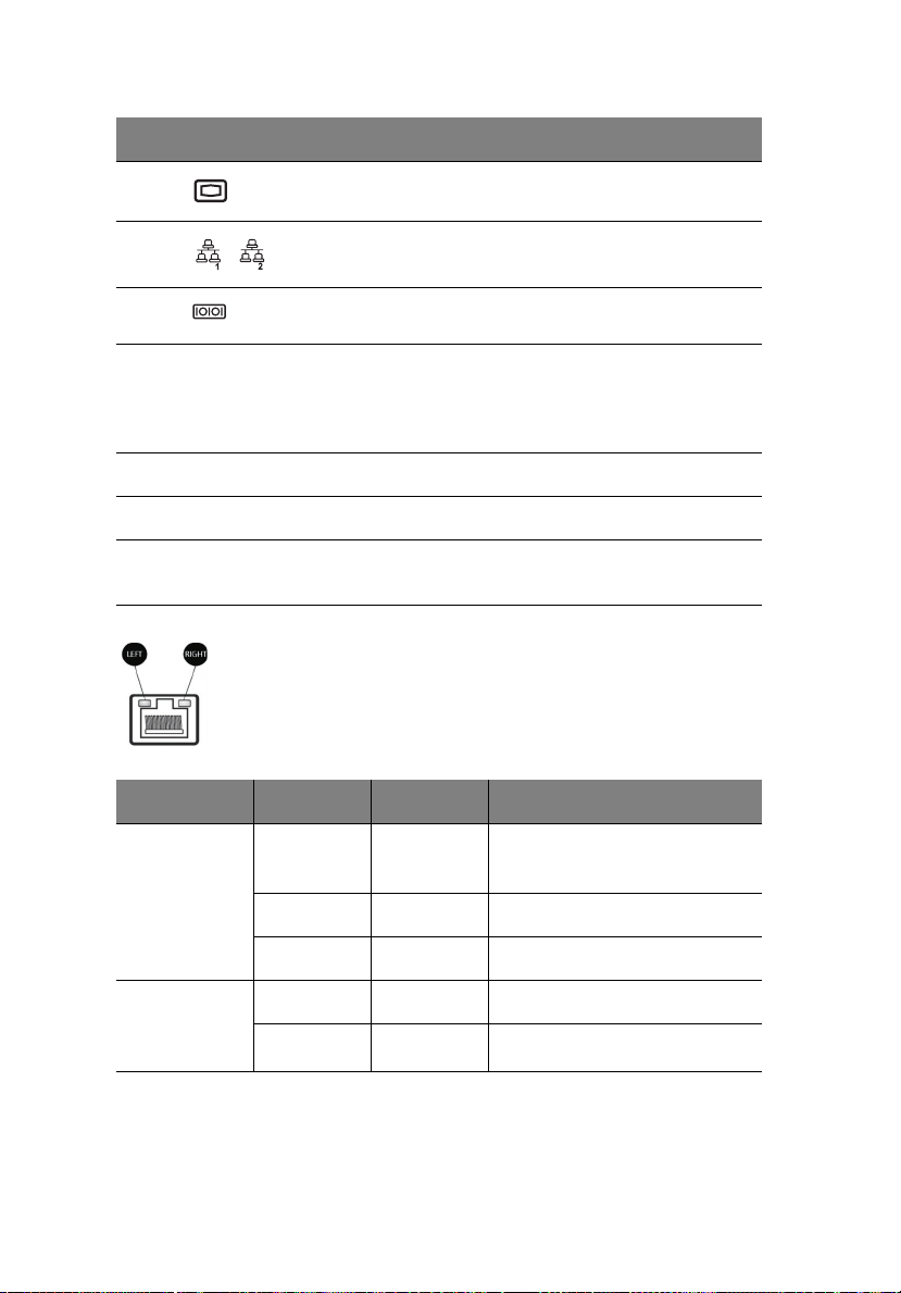
No. Icon Component Description
6 Monitor port Connects to monitors.
1 System tour
7 Gigabit LAN
port
8 Serial port Connects to serial devices.
9 Rear system ID
switch
10 PCI slot covers Protect the vacant expansion slots.
11 System fans Regulate the system airflow.
12 Power supply
module
Connects to an internet or intranet
network.
Press to mark the server unit within a
server group (when rack mounted) for
purpose of identification during
servicing or maintenance procedures.
Provides power to the system.
LAN port LED indicator status
LED indicator LED color LED state Status
RJ45 LED
(left)
N/A Off No connection or
10 Mbps
RJ45 LED
(right)
Green On 100 Mbps
Amber On 1000 Mbps
Yellow On Active connection
Yellow Blinking Transmit/Receive activity
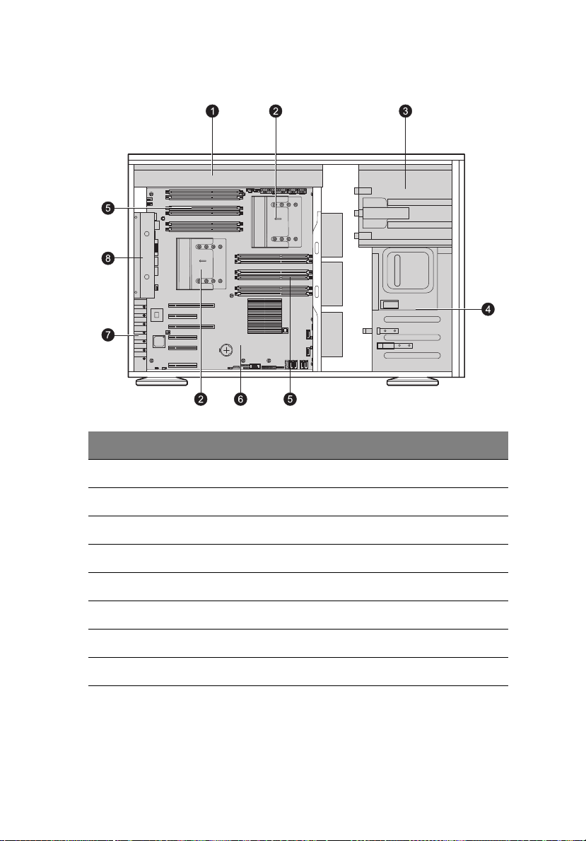
Internal components
No. Component
9
1 Power supply
2 Heat sink fan (HSF) assemblies
3 Sliders for the 5.25" devices
4 HDD carriers
5 DIMM modules
6 Mainboard
7 PCI slot lock
8 System fans
10
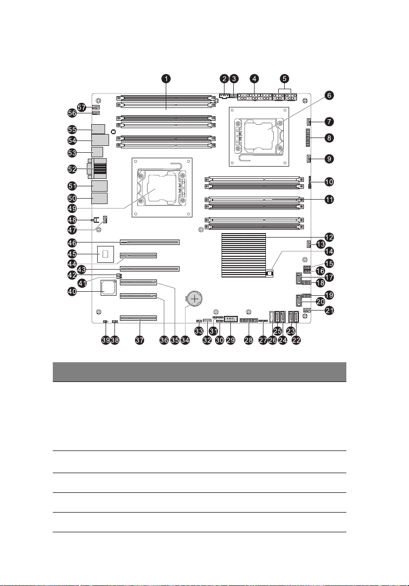
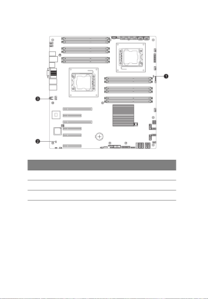
Mainboard Layout
1 System tour
No. Code Description
1 P1 DIMM 3A,
P1 DIMM 3B,
P1 DIMM 2A,
P1 DIMM 2B,
P1 DIMM 1A,
P1 DIMM 1B,
2
3 FAN7/CPU2 CPU2 fan header
4 JPW1 24-pin ATX power connector
5 JPW2/JPW3 8-pin 12V power connectors
2
JI
C1 Power supply SMBbus I2C header
DDR3 DIMM slots for processor 1

No. Code Description
6 CPU2 Processor 2 socket
7 FAN1 System fan header
8 JF1 Front panel control header
9 FAN2 System fan header
10 JD1 Speaker/power LED indicator
11
11 P2 DIMM 3A,
P2 DIMM 3B,
P2 DIMM 2A,
P2 DIMM 2B,
P2 DIMM 1A,
P2 DIMM 1B
12 Intel IOH36 Chip
13 FAN3 System fan header
14 Bios Chip/ Bios ROM
15-16 T-SGPIO 1/2 Serial_Link General Purpose I/O Headers
17 I-SATA0 Intel SB SATA connector 0
18 USB 4/5 Front panel accessible USB connections
19 USB 6/7 Front panel accessible USB connections
20 I-SATA1 Intel SB SATA connector 1
21 FAN4 System fan header
22 I-SATA2 Intel SB SATA connector 2
23 I-SATA3 Intel SB SATA connector 3
DDR3 DIMM slots for processor 2
24 I-SATA4 Intel SB SATA connector 4
25 I-SATA5 Intel SB SATA connector 5
26 USB8 Front panel accessible USB connection

12
No. Code Description
27 USB10 Front panel accessible USB connections
28 JTPM1 Trusted Platform Support Header
29 COM2 Serial connector 2
30 JL1 Chassis intrusion header
31 JP1 For debug only
32 IPMB IPMB header (for an IPMI card)
33 JWD Watch Dog jumper
34 JBAT1 Onboard battery holder
35 Slot3 PCI-E x8 slot (x4 signal)
36 Slot2 PCI-E x8 slot (x4 signal)
37 Slot0 Flex IO slot
38 JPL1 GLAN ports enable/disable jumper
1 System tour
39 JWOR1 Wake-On-Ring header
40 BMC CTRL BMC controller
41 JPG1 VGA enable/disable jumper
42 JPB BMC enable/disable jumper
43 Slot4 PCI-E x16 slot (x8 signal)
44 Slot5 PCI-E x8 slot (x4 signal)
45 LAN CTRL LAN controller
46 Slot6 PCI-E x16 slot (x8 signal)
47 FAN8/CPU1 CPU1 fan header
48 UID SW1 System ID button
49 CPU1 Processor 1 socket

No. Code Description
50 LAN2 LAN2 port
51 LAN1 LAN1 port
13
52 COM1
VGA
53 USB2/3 Rear panel USB ports
54 USB0/1 Rear panel USB ports
55 KB
MS
56 FAN6 System fan header
57 FAN5 System fan header
Serial port (top)
VGA port (bottom)
PS/2 keyboard port
PS/2 mouse port
14
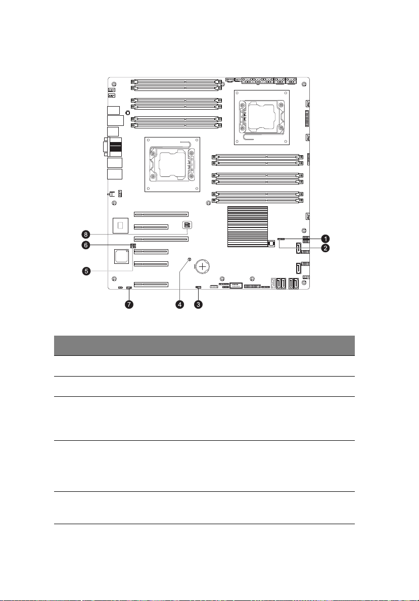
Mainboard jumper settings
1 System tour
No. Code Jumper Default Setting
1 JP7 ME Mode Select Open (Normal)
2 JP5 ME Recovery Open (Normal)
3 JWD Watch Dog 1-2 Close: Reset (default setting)
2-3 Close: NMI
Open: Disabled
4 JBT1 Clear CMOS To clear CMOS, use a metal object
such as a small screwdriver to touch
both pads at the same time to
short the connection.
5 JPG1 Enable VGA 1-2 Close: Enabled (default setting)
2-3 Close: Disabled

No. Code Jumper Default Setting
6 JPB Enable BMC 1-2 Close: Enabled
2-3 Close: Normal (default setting)
7 JPL1 Enable GLAN ports 1-2 Close: Enabled (default setting)
2-3 Close: Disabled
15
8
2
C1/
JI
2
C2
JI
System
Management Bus
(I2C) to PCI and
Close: Enabled
Open: Disabled (default setting)
PCI-Express slots
16
Mainboard LEDs
1 System tour
No. LED Description State Status
1 LE1 Standby power LED Green: On Power on
2 LEM1 BMC heartbeat LED Green: blinking BMC normal
3 LE2 System ID switch LED Blue Unit identified

2 System
setup

18
2 System setup
Setting up the system
Pre-installation requirements
Selecting a site
Before unpacking and installing the system, select a suitable site for
the system for maximum efficiency. Consider the following factors
when choosing a site for the system:
• Near a grounded power outlet.
• Clean and dust-free.
• Stable surface free from vibration.
• Well-ventilated and away from sources of heat.
• Protected from electromagnetic fields produced by electrical
devices such as air conditioners, radio and TV transmitters, etc.
Package contents
Ensure you have the following items:
• Acer AT150 system
• Acer AT150 accessory box
If any of the above items is damaged or missing, contact your dealer
immediately.
Save the boxes and packing materials for future use.

19
Connecting peripherals
Refer to the illustration below for specific connection instructions on
the peripherals you want to connect to the system.
Front connections

20
Rear connections
2 System setup
Note: Consult the operating system manual for information on
how to configure the network setup.
Caution: Do not route the power cord where it will be walked on
or pinched by items placed against it. The server is designed to be
electrically grounded (earthed). To ensure proper operation, plug
the power cord into a properly grounded AC outlet only.

21
Turning on the system
After making sure that you have properly set up the system and
connected all the required cables, you can now power on the system.
To power on the system
After plugging in the power cord, press the power button.
The system starts up and displays a welcome message on the monitor.
After that, a series of POST messages appears. The POST messages
indicate if the system is running well or not.
Note: If the system does not turn on or boot after pressing the
power button(s), go to the next section for the possible causes of
the boot failure.
Aside from the POST messages, you can determine if the system is in
good condition by checking if the following occurred.
• The power indicator on the front panel lights up green.
• The Num Lock, Caps Lock, and Scroll Lock indicators on the
keyboard light up.

22
2 System setup
Power-on problems
If the system does not boot after you have applied power, check
thefollowing factors that might have caused the boot failure.
• The external power cord may be loosely connected.
Check the power cord connection from the power source to the
power supply module AC input connector on the rear panel. Make
sure that the power cord is properly connected to the power
source and to the AC input connector.
• No power comes from the grounded power outlet.
Have an electrician check your power outlet.
• Loose or improperly connected internal power cables.
Check the internal cable connections. If you are not confident to
perform this step, ask a qualified technician to assist you.
Warning! Make sure all power cords are disconnected from the
electrical outlet before performing this task.
Note: If you have gone through the preceding actions and the
system still fails to boot, ask your dealer or a qualified technician
for assistance.

23
Configuring the system OS
Acer Smart Setup assists you to conveniently install your choice of
operating system.
To start using Smart Setup, follow the steps below.
1 Locate the Smart Setup included in the system package.
2 If an optional DVD drive is not installed in the server, connect an
external DVD drive to your system. Press the Stop/Eject button on
the DVD drive to eject the disc tray.
3 When the disc tray slides open, insert the Smart Setup DVD with
the label or title side of the disc facing upward.
Note: When handling the disc, hold it by the edges to avoid
smudges or fingerprints.
4 Gently press the disc down to make sure that it is properly
inserted.
Caution! While pressing the disc, be careful not to bend the disc
tray. Make sure that the disc is properly inserted before closing
the disc tray. Improper insertion may damage both the disc and
the CD-ROM drive.
5 Gently press the drive Stop/Eject button again to close the disc
tray.
6 On the Acer Smart Setup window, select OS Installation.
7 Follow all onscreen instructions.
For more information, refer to the Smart Setup Help file.
Note: The Windows or Linux OS disc is needed when you install
the OS with the Smart Setup.

24
2 System setup
Turning off the system
There are two ways to turn off the server — via software or via
hardware. The software procedure below applies to a system running
the Windows operating system. For further operating system
shutdown procedures, refer to the related user documentation.
To turn off the system via software:
1 Press <Ctrl> + <Alt> + <Delete> on the attached keyboard or click
Start on the Windows taskbar.
2 Select Shut Down.
3 Select Shut down from the drop-down window then click on OK.
To turn off the system via hardware:
If you cannot shut down the server using the software, press and hold
the power button for at least four seconds. Quickly pressing the button
may put the server in a Suspend mode only.

3 System upgrades

26
3 System upgrades
Installation precautions
Before you install any server component, it is recommended that you
read the following sections first. These sections contain important ESD
precautions along with pre-installation and post-installation
procedures.
ESD precautions
Electrostatic discharge (ESD) can damage static-sensitive hardware
components, such as the processor, disk drives, and the system board.
Always observe the following precautions before you install a server
component:
• Do not remove a component from its protective packaging until
you are ready to install it.
• Do not touch the component pins, leads, or circuitry.
• Components with a Printed Circuit Board (PCB) assembly should
always be laid with the assembly-side down.
• Wear a wrist grounding strap and attach it to a metal part of the
server before handling components. If a wrist strap is not
available, maintain contact with the server throughout any
procedure requiring ESD protection.
• Keep the work area free of nonconductive materials, such as
ordinary plastic assembly aids and foam packing.

27
Pre-installation instructions
Perform the steps below before you open the server or before your
remove or replace any component.
Warning! Failure to properly turn off the server before you start
perform any hardware configuration may cause serious damage
and bodily harm. Do not attempt the procedures described in the
following sections unless you are a qualified service technician.
1 Turn off the server and all connected peripherals.
2 Unplug all power cables from their outlets.
3 Disconnect all telecommunication cables from their ports.
4 Place the server on a flat, stable surface.
5 Open the server according to the instructions on page 38.
6 Follow the ESD precautions described in the previous section when
handling a server component.
Post-installation instructions
Perform the steps below after installing a server component.
1 See to it that all components are installed according to the
described step-by-step instructions.
2 Reinstall any expansion board(s), peripheral(s), bracket(s) and
system cable(s) that have previously been removed.
3 Reinstall the side panel.
4 Reconnect the power, peripheral, and telecommunication cables.
5 Turn on the system.

28
3 System upgrades
Opening the server
Caution: Before you proceed, make sure that you have turned off
the system and all peripherals connected to it. Read the
Pre-installation instructions section on page 27.
You need to open the server before you can install upgrade
components. The left side panel is removable to allow access to the
server’s internal components. Refer to the following sections for
instructions.
Removing and installing the side panel
Removing the side panel
1 Observe the ESD precautions described on page 26.
2 Observe the pre-installation instructions described on page 26.
3 Remove the two screws (1) on the rear edge of the side panel.
4 Slide and hold the locking switch (2).
5 Slide the side panel toward the rear of the server to disengage it
then lift the panel away from the server (3).

29
Installing the side panel
1 Observe the pre-installation instructions described on page 26.
2 Position the side panel so that the tabs on the cover align with the
slots on the server, then slide the side panel toward the front of
the server until you hear a click sound.
3 Replace the two screws.
Configuring the hard disk drive
The AT150 F1 accommodates up to four 3.5-inch or eight 2.5-inch hotplug SATA/SAS hard disk drives.
By default, the system is shipped with only one hard disk drive bay. To
install additional hard disk drives in the second hard disk drive bay, you
need to purchase the optional bay and SAS RAID controller.
Note: Maximum HDD support is SKU-dependent.

30
3 System upgrades
Accessing the drive bays
Since SATA/SAS drives have hot-plug capability, you do not need to
access the inside of the chassis or power down the system to install or
replace SATA/SAS drives. Access the HDD bay door as follows:
1 Unlock the drive bay door.
2 Open the HDD bay door as shown.
Note: The operating system you use must have RAID support to
enable the hot-plug capability of the SATA drives.
Caution! When working around the SATA backplane, do not
touch the backplane with any metal objects and make sure no
cables touch the backplane. Also, regardless of how many SATA
drives are installed, all four drive carriers must remain in the
chassis to maintain proper airflow.

31
2.5-inch HDD bays
3.5-inch HDD bays
Hard disk drive configuration guidelines
Observe these guidelines when replacing or installing a hard disk drive.
• Use only qualified SAS or SATA HDDs. To purchase a SAS or SATA
HDD, contact your local representative.
• Install hard disk drives in the special drive carriers that fit in the
hard drive bays.
• Before removing an HDD, make sure to back up all important
system files.
• Check HDD status by checking the status LED indicators on the
HDD carrier.
• The hard disk drive carriers must be installed in the following
order:

32
3 System upgrades
Determining the drive status
Each HDD carrier features two status LED indicators (see page 6) to
display the hard drive status. If you are replacing a failed HDD,
determine which drive has failed by checking the hot-plug HDD status
indicators.
3.5-inch HDD
2.5-inch HDD
Description
Green Red
Onboard SATA or RAID card without SGPIO support
HDD present On Off
HDD access Blink Off
RAID card with SGPIO support
HDD present no access SAS: On
SATA:Off
HDD access Blink
HDD failure On
HDD removal Off Off
HDD insertion and rebuilding Blink (1 Hz)
HDD locate Blink (4 Hz)

Removing a hard disk drive with carrier
System with 2.5-inch
HDD
System with 3.5-inch
HDD
If you intend to replace a HDD and need to remove the old drive,
proceed to the instructions below.
1 Observe the ESD precautions described on page 26.
2 Observe the pre-installation instructions described on page 26.
3 If necessary, unlock (1) the bezel door then pull it open (2).
33

34
4 Remove the hard disk drive with carrier.
(1) Unlock the HDD carrier latch.
(2) Slide the HDD carrier latch to release the lever.
(3) Pull the lever and slide the carrier from the server.
3.5-inch HDD with carrier
3 System upgrades

2.5-inch HDD with carrier
5 If you have no plans of installing a new HDD to the server, you
must reinstall the blank HDD carrier or HDD cover to maintain
proper airflow.
6 Close the bezel door.
7 Observe the post-installation instructions on page 27.
35

36
System with 2.5-inch
HDD
System with 3.5-inch
HDD
Installing a hard disk drive with carrier
1 Observe the ESD precautions described on page 26.
2 If necessary, unlock the bezel door then pull it open.
3 System upgrades
3 Remove the hard disk drive cover.
Pull the HDD cover straight out of the drive bay.
4 Install the hard disk drive with carrier.

37
(1) Use the lever to push the HDD carrier in the empty bay until it
locks into place.
(2) Close the HDD carrier lever.
(3) Lock the HDD carrier.
3.5-inch HDD with carrier
2.5-inch HDD with carrier
5 Close the bezel door.
6 Observe the post-installation instructions on page 27.

38
3 System upgrades
Configuring a 5.25-inch storage device
The three 5.25-inch device bays support a variety of storage devices for
additional storage capacity and scalability.
By default, the system ships with a DVD-ROM drive installed on the
topmost device bay. You can choose to replace these default drives, or
you can install a new storage device on the second device bay.
Please ensure all installed devices support the SATA interface.
Installing an optional 5.25-inch storage device
1 Perform the pre-installation instructions described on page 26.
2 Remove the side panel described on page 28.
3 Pull the locking tab (1) to release the empty 5.25-inch drive cage.
4 Pull out the dummy 5.25-inch drive cage (2).

39
5 Remove the four screws (1) that attach the metal brackets to the
empty 5.25-inch drive cage. Detach the metal brackets (2).
6 Align the metal brackets with the new storage device and make
sure the arrow (1) is pointing to the front. Align the notches on
the brackets with the holes (2) on the device.
7 Use four screws to secure the metal brackets to the new 5.25-inch
storage device.

40
3 System upgrades
8 Insert the new 5.25-inch storage device with brackets into the
bay (1). The drive is properly inserted if you hear a click and the
locking tab locks into place.
9 Connect the power (2) and SATA cables (3) to their connectors on
the main board.
10 Re-install the side panel and close the bezel door.
11 Observe the post-installation instructions described on page 27.

Removing a 5.25-inch storage device
1 Perform the pre-installation instructions described on page 26.
2 Remove the side panel described on page 28.
3 Disconnect the SATA (2) and power (1) cables connected to the
storage device. Pull out the tab (3) and pull out the device from
the drive bay (4).
41
4 If you intend to install a new storage device, refer to the previous
section.
5 Re-install the side panel and close the bezel door.
6 Observe the post-installation instructions described on page 27.

42
3 System upgrades
Replacing the processor and heatsink fan assembly
Notes:
• Always connect the power cord last and always remove it before
adding, removing or changing any hardware components. Make
sure that you install the processor in the CPU socket before you
install the CPU heatsink fan assembly.
• If you buy a processor separately, make sure that you use an
Intel-certified multidirectional heatsink fan assembly only.
• Make sure to install the mainboard in the server before you
install the CPU heatsink fan assembly.
• When receiving a mainboard without a processor pre-installed,
make sure that the plastic CPU socket cap is in place and none of
the socket pins is bent; otherwise, contact your retailer
immediately.
Removing and installing the heatsink fan assembly
Removing the heatsink fan assembly
Warning! We do not recommend that the processor or the
heatsink assembly be removed. However, if you do need to
uninstall the heatsink fan assembly, please follow the instructions
below to prevent damage to the processor or the CPU socket.
1 Observe the pre-installation instructions on page 26.
2 Remove the side panel described on page 28.
3 Lay the server on its side (components showing).

4 Disconnect the heatsink fan cable (1) from its mainboard
connector and lift the heatsink fan (2).
43

44
3 System upgrades
5 Use a screwdriver to loosen the four heatsink screws from the
mainboard by turning it counter-clockwise (1).
6 Lift the heatsink (2) away from the processor.
7 Lay down the heatsink in an upright position — with the thermal
patch facing upward. Do not let the thermal patch touch the work
surface.
8 Observe the post-installation instructions described on page 27.

45
Installing the heatsink and fan assembly
Caution! The heatsink fan assembly has a thermal interface
material (TIM) on the underside. Use caution so that you do not
damage the TIM. If a protective film is installed on the TIM,
remove it.
1 Perform the pre-installation instructions described on page 26.
2 Remove the side panel described on page 28.
3 Lay the server on its side (components showing).
4 Do not apply any thermal grease to the heatsink or the processor
die; the required amount has already been applied.
5 Place the heatsink on top of the processor (1) so that the four
mounting holes are aligned with those on the (preinstalled)
heatsink retention mechanism.
6 Use a screwdriver to tighten the four heatsink screws. Do not fully
tighten the screws or you may damage the CPU.

46
Air Flow
Arrow
3 System upgrades
7 Insert the heatsink fan (1) and connect the heatsink fan cable (2)
to its connector on the mainboard.
Note: When inserting the heatsink fan, make sure the air flow
arrow on the fan is pointing up.
8 Observe the post-installation instructions described on page 27.

47
Removing and installing the processor
Processor configuration guidelines
This server has two LGA 1366 processor sockets for supporting Intel®
Xeon® 5500 / 5600 series series processors. The supplied processor may
be upgraded.
Observe the following guidelines when replacing or installing a
processor.
• The CPU socket must always be populated. If no processor is
installed in this socket, the system will fail to boot.
• Before removing the processor, make sure to back up all important
system files.
• Handle the processor and the heatsink fan assembly carefully.
Damage to either may prevent the system from functioning
properly.
Replacing the processor
Warning! The processor becomes very hot when the system is on.
Allow it to cool off first before handling.
1 Perform the pre-installation instructions described on page 26.
2 Remove the side panel described on page 28.
3 Lay the server on its side (components showing).
4 Remove the heatsink fan assembly (see "Removing and installing
the heatsink fan assembly" on page 42).
5 Remove the default processor.
(1) Press down on the load lever then release out of the retention
tab.
(2) Rotate the load lever to the fully open position until the
retention plate is completely lifted.

48
3 System upgrades
(3) Grasp the processor by its edges and lift it out of its socket.
(4) Store the old processor inside an anti-static bag.
6 Remove the new processor from its protective packaging.
7 Install the new processor.
(1) Make sure that the alignment tabs on the socket fit the two
notches located on the edges of the processor. The pins are

keyed in such a way that you cannot install the processor in
the wrong orientation without bending the pins.
(2) Hold the processor by its edges then insert it in the socket.
(3) Close the retention plate.
(4) Engage the load lever back in place and secure the load lever
under the load lever retention tab .
8 Apply the thermal interface material.
(a) Use an alcohol pad to wipe off the old thermal grease from
both the HSF assembly and the processor socket retention
plate.
(b) Apply a thin layer of thermal interface material before
installing the HSF.
Make sure that only a very thin layer is applied so that both
contact surfaces are still visible.
9 Install the heatsink fan assembly (see "Installing the heatsink and
fan assembly" on page 45).
10 Observe the post-installation instructions described on page 27.
49

50
3 System upgrades
Upgrading the system memory
System memory interface
The server has a total of twelve DIMM slots. Each CPU controls three
channels and each channel has two slots. The DIMM slots support
DDR3-1333 registered/unbuffered ECC memory modules.
In each channel, the slot farthest from the CPU is slot A (1A, 2A and 3A
in blue) while the nearest one is slot B (1B, 2B and 3B in black).
Independent mode
• For all memory modes, slot A in each channel should be populated
first and then slot B. If slot A is empty, then slot B cannot be used.
• For a single-processor server configuration, install the processor in
CPU1 socket and the memory modules in slots P1DIMM 1A to
P1DIMM 3B.
• If there is a processor installed in CPU2 socket, the system will
enable the slots P2DIMM 1A to P2DIMM 3B.

• It is recommended to install the DIMM modules in the following
sequence:
For single processor
• Populate slot 1A first, followed by slots 2A, 3A,1B, 2B and 3B.
• The memory slots for processor 2 are not available.
For dual processors
• Populate DIMM slots 1A of each CPU first, followed by slots
2A, 3A,1B, 2B and 3B.
• If mixing different DIMMs in one channel, the DIMM with higher
rank and density should be populated from slot A.
Memory population for independent mode
Single processor configuration
Channel 1
DIMM slots
Configuration 1B 1A 2B 2A 3B 3A
AX
BXX
CXXX
DXXXX
E X X X X X X SR, DR RDIMMs
Channel 2
DIMM slots
Channel 3
DIMM slots
Notes
only
51
Notes: 1. Place DIMMs in “X” location.
2. DIMM population must correspond to the above tables.
3. DIMM modules support 1 GB, 2 GB and 4 GB DIMMs.
4. DIMM modules support 8 GB (support depends on
availability).
5. Do not mix UDIMMs with RDIMMs.

52
3 System upgrades
Dual processors configuration
CPU 1 CPU 2
Configuration 1B1A2B2A3B3A1B1A2B2A3B3A
AX X
B XXX
CXX XX
D XXXXXX
E XXXX XXXX
F XXXXXXXXX
G XXXXXXXXXXXX
Notes: 1. Place DIMMs in “X” location.
2. DIMM population must correspond to the above tables.
3. DIMM modules support 1 GB, 2 GB and 4 GB DIMMs.
4. DIMM modules support 8 GB DIMMs (support depends
on availability).
5. Do not mix UDIMMs with RDIMMs.

Mirroring mode
• For mirroring mode, the memory contains a primary image and a
copy of the primary image. Therefore, the effective size of the
memory is reduced by at least one-half.
• Channel 3 has no function and cannot be populated under this
mode.
• Follow the population rules described in independent mode.
• DIMM modules installed in channels 1 and 2 must be identical —
memory modules in slots 1A and 2A should be the same type, size
and manufacturer. The same applies to slots 1B and 2B. However,
it is not necessary for slot A to have the same memory module as
slot B within a channel.
• The same rule applies to the processor 2.
Memory population for mirroring mode
Single processor configuration
Channel 1
DIMM
slots
Configuration 1B 1A 2B 2A 3B 3A
AXXNANA
B XXXXNANASR, DR RDIMMs only
Channel 2
DIMM
slots
Channel 3
DIMM
slots
Notes
53
Notes: 1. Place DIMMs in “X” location.
2. DIMM population must correspond to the above tables.
3. DIMM modules support 1 GB, 2 GB and 4 GB DIMMs.
4. DIMM modules support 8 GB DIMMs (support depends
on availability).
5. Do not mix UDIMMs with RDIMMs.

54
3 System upgrades
Dual processors configuration
CPU 1 CPU 2
Configuration
A
B
C
D
1B 1A 2B 2A 3B 3A 1B 1A 2B 2A 3B 3A
XX
XX XX
XXXX X X
XXXX XXXX
Notes: 1. Place DIMMs in “X” location.
2. DIMM population must correspond to the above tables.
3. DIMM modules support 1 GB, 2 GB and 4 GB DIMMs.
4. DIMM modules support 8 GB DIMMs (support depends
on availability).
5. Do not mix UDIMMs with RDIMMs.
Lockstep mode
• In Lockstep Channel Mode, each memory access is a 128-bit data
access that spans Channel 1 and Channel 2. This is done to support
SDDC for DRAM devices with 8-bit wide data ports. The same
address is used on both channels such that an address error on any
channel is detectable by ECC. Lockstep Channel mode is the only
RAS mode that supports x8 SDDC.
• Channel 3 has no function and cannot be populated in this mode.
• Follow the population rules described in independent mode.
• DIMM modules installed in channels 1 and 2 must be identical —
1A and 2A should be the same type, size and manufacturer.
1B and 2B memory should be the same type, size and
manufacturer. However, it is not necessary for slot A to have the
same memory module as slot B within a channel.
• The same rule applies to processor 2.

Memory population for lockstep mode
Single processor configuration
Channel 1
DIMM slots
Configuration 1B 1A 2B 2A 3B 3A
AXXNANA
BXXXXNANA
Notes: 1. Place DIMMs in “X” location.
2. DIMM population must correspond to the above tables.
3. DIMM modules support 1 GB, 2 GB and 4 GB DIMMs.
4. DIMM modules support 8 GB DIMMs (support depends
on availability).
5. Do not mix UDIMMs with RDIMMs.
Channel 2
DIMM slots
Channel 3
DIMM slots
Notes
Dual processors configuration
CPU 1 CPU 2
Configuration 1B1A2B2A3B3A1B1A2B2A3B3A
A X X NANA NANA
B X X NANA X X NANA
C XXXXNANA X XNANA
D XXXXNANAXXXXNANA
55
Notes: 1. Place DIMMs in “X” location.
2. DIMM population must correspond to the above tables.
3. DIMM modules support 1 GB, 2 GB and 4 GB DIMMs.
4. DIMM modules support 8 GB DIMMs (support depends
on availability).
5. Do not mix UDIMMs with RDIMMs.

56
3 System upgrades
Sparing mode
• In this mode, if the system detects degrading memory and did not
crash, the data in the failed channel will be copied to the spare
channel. The failed channel is then isolated and the spare channel
becomes active. However, any uncorrectable error that happens
before the isolation will still cause the system to stop normal
operation.
• Channel 3 is the spare channel. Therefore, the effective size will be
reduced by one-third.
• Follow the population rules described in the independent mode.
• Sparing mode requires that all three channels use identical DIMMs.
1A, 2A and 3A should be the same type, size and manufacturer,
likewise for 1B, 2B and 3B. The same rule applies to processor 2.
• Intel® Xeon® Processor 5500 Series CPUs do NOT support the
memory sparing mode.
Memory population for sparing mode
Single processor configuration
Channel 1
DIMM slots
Configuration 1B 1A 2B 2A 3B 3A
AXXX
BXXXXXX
Channel 2
DIMM slots
Channel 3
DIMM slots
Notes
Notes: 1. Place DIMMs in “X” location.
2. DIMM population must correspond to the above tables.
3. DIMM modules support 1 GB, 2 GB and 4 GB DIMMs.
4. DIMM modules support 8 GB DIMMs (support depends
on availability).
5. Do not mix UDIMMs with RDIMMs.

Dual processors configuration
CPU 1 CPU 2
Configuration1B1A2B2A3B3A1B1A2B2A3B3A
A XXX
B XXXXXX
C XXXXXXXXX
D XXXXXXXXXXXX
Notes: 1. Place DIMMs in “X” location.
2. DIMM population must correspond to the above tables.
3. DIMM modules support 1 GB, 2 GB and 4 GB DIMMs.
4. DIMM modules support 8 GB DIMMs (support depends
on availability).
5. Do not mix UDIMMs with RDIMMs.
57

58
Density
Rank
Bit organization
Speed
3 System upgrades
Memory identification
Generally, there are some memory information printed on the label of
the DIMM module. Different vendors may have different formats but
the convention is usually like this:
Item Description
Density 1 GB, 2 GB, 4 GB, 8 GB.
• Intel Xeon 5500 series processor supports DIMM
organized by 1Gb or 2Gb DRAM chips.
• Intel Xeon 5600 series processor supports DIMM
organized by 1Gb, 2Gb or 4Gb DRAM chips.
Rank 1R = Single Rank
2R = Dual Rank
4R = Quad Rank
Note: If quad rank DIMM is used, a maximum of only two
DIMMs per channel can be supported.
Bit
Organization
Speed PC3 - 6400 => DDR3- 800
This platform supports x4 and x8.
Note: It is not recommended to mix DIMMs with different
ranks in one system.
PC3 - 8500 => DDR3- 1066
PC3 - 10600 => DDR3- 1333
PC3 - 12800 => DDR3- 1600

Installing a memory module
Warning! Memory of the identical size, speed, and organization
must be installed in the same colored DIMM slots.
1 Observe the pre-installation instructions on page 26.
2 Remove the side panel described on page 28.
3 Lay the server on its side (components showing).
4 Locate the DIMM slot on the mainboard.
5 Install the memory module.
(a) Align then insert the DIMM into the socket (1).
(b) Push the DIMM to the socket until the retaining clips snap
inward (2).
59
Note: The DIMM slot is slotted to ensure proper installation. If you
insert a DIMM but it does not fit easily into the socket, you may
have inserted it incorrectly. Reverse the orientation of the DIMM
and insert it again.
6 Observe the post-installation instructions described on page 27.
The system automatically detects the amount of memory installed.
Run the BIOS setup to view the new value for total system memory
and make a note of it.

60
3 System upgrades
Removing a memory module
Important: Before removing any DIMM from the mainboard,
make sure to create a backup file of all important data.
1 Perform steps 1 through 3 of the previous section.
2 Remove the memory module.
(a) Press the holding clips on both sides of the slot outward to
release the DIMM (1).
(b) Gently pull the DIMM upward to remove it from the slot (2).
3 If you intend to install a new DIMM, refer to the previous section,
otherwise observe the post-installation instructions described on
page 27.

61
Installing an expansion card
I/O interface
The AT150 F1 has six PCI bus slots with separate bus segments, namely:
®
• Two PCI Express
• Two PCI Express
• One PCI Express
• One PCI Express
2.0 x8 in x16 (slots 4 and 6)
®
2.0 x4 in x8 (slots 2 and 3)
®
1.0 x4 in x8 (slot 5)
®
2.0 x8 (slot 0 - Flex IO)
Installing a SAS card
1 Observe the pre-installation instructions on page 26.
2 Remove the side panel described on page 28.
3 If necessary, remove any cables that prevent access to the PCI slot.
4 Locate an empty expansion slot that is compatible with the
specification of the card you intend to install.
5 Unclip the restraining latch (1) and open in the direction (2) shown
below .
6 Remove the screw holding the slot in place (3).
7 Slide out the slot shield (4).

62
Caution: Do not discard the slot cover. If the expansion card is
removed in the future, the slot cover must be reinstalled to
maintain proper system cooling.
3 System upgrades
Remove the expansion card from its protective packaging,
handling it by the edges.
8 Insert the card in the selected slot (5) making sure that the card is
properly seated.
9 Insert the screw holding the card in place (6).

10 Close the restraining latch (7).
11 Connect the appropriate cables to the card.
12 Observe the post-installation instructions described on page 27.
When you turn on the system, the BIOS setup automatically
detects and assigns resources to the new device (applicable only to
Plug-and-Play expansion cards).
63

64
3 System upgrades

4 System BIOS

66
4 System BIOS
BIOS overview
BIOS setup is a hardware configuration program built into the system's
Basic Input/Output System (BIOS). Since most systems are already
properly configured and optimized, there is no need to run this utility.
You will need to run this utility under the following conditions.
• When changing the system configuration settings.
• When redefining the communication ports to prevent any
conflicts.
• When modifying the power management configuration.
• When changing the password or making other changes to the
security setup.
• When a configuration error is detected by the system and you are
prompted ("Run Setup" message) to make changes to the BIOS
setup.
Note: If you repeatedly receive Run Setup messages, the battery
may be bad. In this case, the system cannot retain configuration
values in CMOS. Ask a qualified technician for assistance.
BIOS setup loads the configuration values in a battery-backed
nonvolatile memory called CMOS RAM. This memory area is not part of
the system RAM, which allows configuration data to be retained when
power is turned off.
Before you run the AMI BIOS Setup Utility, make sure that you have
saved all open files. The system reboots immediately after you close the
Setup.
Note: AMI BIOS Setup Utility will be simply referred to as "Setup"
"Setup Utility" in this guide.
or
The screenshots used in this guide display default system values.
These values may not be the same those found in your system.

67
Entering BIOS Setup
1 Turn on the server and the monitor.
If the server is already turned on, close all open applications, then
restart the server.
2 During POST, press <F2>.
If you fail to press <F2> before POST is completed, you will need to
restart the server.
The Setup Main menu will be displayed showing the menu bar.
Use the left and right arrow keys to move between selections on
the menu bar.
BIOS setup primary menus
The tabs on the Setup menu bar correspond to the seven primary BIOS
Setup menus, namely:
•Main
•Advanced
•Power
•Security
• Server Management
•Boot
• Exit
In the descriptive table following each of the menu screenshots,
settings in boldface are the default and suggested settings.

68
4 System BIOS
BIOS setup navigation keys
Use the following keys to move around the Setup Utility:
• Left and Right arrow keys – Move between selections on the menu
bar.
• Up and Down arrow keys – Move the cursor to the field you want.
• PgUp and PgDn keys – Move the cursor to the previous and next
page of a multiple page menu.
• Home – Move the cursor to the first page of a multiple page menu.
• End – Move the cursor to the last page of a multiple page menu.
• + and - keys – Select a value for the currently selected field (only if
it is user-configurable). Press these keys repeatedly to display each
possible entry, or the Enter key to choose from a pop-up menu.
Note: Grayed-out fields are not user-configurable.
• Enter key – Display a submenu screen.
Note: Availability of submenu screen is indicated by a (>).
• Esc – If you press this key:
• On one of the primary menu screens, the Exit menu displays.
• On a submenu screen, the previous screen displays.
• When you are making selections from a pop-up menu, closes
the pop-up without making a selection.
• F1 – Display the BIOS setup General Help panel.
• F9 – Press to load default system values.
• F10 – Save changes made the Setup and close the utility.

Main menu
Parameter Description Option
69
System
Overview
System BIOS
Version
Build Date
Processor
CPU Type
Speed
Physical Count
Logical Count
System Memory
Size
Version of the BIOS used in your system.
Date when the BIOS Setup Utility was created.
Displays the type of CPU detected by the BIOS.
Displays the speed of the CPU detected by the BIOS.
Displays the number of processors detected by the BIOS.
Displays the number of CPU cores detected by the BIOS.
Displays the amount of memory detected by the BIOS.

70
Parameter Description Option
4 System BIOS
Quiet Boot Modifies the bootup screen options
between POST messages or the OEM
logo. Select Disabled to display the
POST messages. Select Enabled to
display the OEM logo instead of the
normal POST messages.
System Date Sets the date following the weekday-month-day-year
format.
System Time Sets the system time following the hour-minute-second
format.
Enabled
Disabled

Advanced menu
The Advanced menu display submenu options for configuring the
function of various hardware components. Select a submenu item,
then press <Enter> to access the related submenu screen.
71

72
4 System BIOS
Processor Configuration
This submenu displays the status of the processor as detected by the
BIOS, including items such as the processor's type, frequency, and
Cache L1, L2, L3 settings.
Parameter Description Options
Ratio CMOS Setting This option allows the user to set
C1E Support Select Enabled to enable Enhanced
Hardware
Prefetcher
(Available when
supported by the
CPU)
Adjacent Cache
Line Prefetch
(Available when
supported by the
CPU)
MPS and ACPI
MADT Ordering
the ratio between the CPU Core
Clock and the FSB Frequency.
Halt State support. C1E significantly
reduces the CPU's power
consumption by reducing the CPU's
clock cycle and voltage during a
Halt State.
If set to Enabled, the hardware
prefetcher will prefetch streams of
data and instructions from the main
memory to the L2 cache to improve
CPU performance.
The CPU prefetches the cache line
for 64 bytes if this feature is set to
Disabled.
The CPU will prefetch both cache
lines for 128 bytes as comprised if
this feature is set to Enabled.
This feature allows the user to
configure the MPS (Multi-Processor
Specifi cations) and ACPI settings
for the main board. Select Modern
Ordering if you are using XP or a
newer version of the Windows OS.
Select Legacy Ordering if you are
using 2000 or an earlier version of
the Windows OS.
Enabled
Disabled
Enabled
Disabled
Enabled
Disabled
Modern
Ordering
Legacy
Ordering

Parameter Description Options
73
Intel®
Virtualization
Technology
(Available when
supported by the
CPU)
Execute-Disable Bit
Capability
(Available if
supported by the
OS & the CPU)
Simultaneous
Multi-Threading
(Available when
supported by the
CPU)
Active Processor
Cores
Select Enabled to enable Intel
Virtualization Technology support,
which will allow one platform to
run multiple operating systems and
applications in independent
partitions, creating multiple
"virtual" systems in one physical
computer.
Select Enabled to enable the
Execute Disable Bit which will allow
the processor to designate areas in
the system memory where an
application code can execute and
where it cannot, thus preventing a
worm or a virus from flooding
illegal codes to overwhelm the
processor or damage the system
during an attack.
Set to Enabled to use the
Simultaneous Multi-Threading
Technology, which will result in
increased CPU performance.
Set to Enabled to use a processor's
Second Core and above. (Please
refer to Intel's web site for more
information.)
Enabled
Disabled
Enabled
Disabled
Enabled
Disabled
All
1
2
Intel® EIST
Technology
Intel® Turbo Boost
(Available when
Intel® EIST
Technology is
enabled)
EIST (Enhanced Intel SpeedStep
Technology) allows the system to
automatically adjust processor
voltage and core frequency to
reduce power consumption and
heat dissipation.
Select Enabled to use the Turbo
Mode to boost system performance.
Enabled
Disabled
Enabled
Disabled

74
Parameter Description Options
4 System BIOS
Performance/Watt
Select
Intel® C-State Tech When this item is set to enabled,
C3 State This feature allows the user to
C6 State This feature allows the user to
C-State package
limit setting
C1 Auto Demotion When this feature is enabled, the
C3 Auto Demotion When this feature is enabled, the
Power Optimized: Turbo Boost
engages after P0 state is sustained
for more than 2 seconds.
Traditional: Turbo Boost engages
even for P0 state for less than 2
seconds.
the system will automatically set CState to C2, C3, or C4 state.
decide how the onboard 5500
Series processor will act at C3 State.
decide how the onboard 5500
Series processor will act at C6 State.
If set to Auto, the AMI BIOS will
automatically set the limit on the CState package register.
CPU will conditionally demote C3,
C6 or C7 requests to C1 based on
un-core auto-demote information.
CPU will conditionally demote C6 or
C7 requests to C3 based on un-core
auto-demote information.
Power
Optimized
Traditional
Enabled
Disabled
ACPI 2
ACPI 3
Disabled
Enabled
Disabled
Auto, C1, C3,
C6, and C7
Enabled
Disabled
Enabled
Disabled
ACPI T State When this feature is enabled, CPU
Throttling state will be reported in
the ACPI (Advanced Confi guration
and Power Interface) protocol.
Intel AES-NI Select Enabled to enable CPU new
instructions for AES. These
instructions can be utilized by
software to accelarate performance
of AES applications.
Enabled
Disabled
Enabled
Disabled

Parameter Description Options
75
Clock Spread
Spectrum
Select Enable to enable Clock
Spectrum support, which will allow
the BIOS to monitor and attempt to
reduce the level of Electromagnetic
Interference caused by the
components whenever needed.
Enabled
Disabled
ATA Controller Configuration
When this submenu is selected, the AMI BIOS automatically detects the
presence of IDE or SATA devices and displays the following items.
Parameter Description Options
SATA#1
Configuration
Configure
SATA#1 as
ICH RAID
CodeBase
(Available
when the
option-RAID
is selected.)
Select Compatible to set SATA#1 to
legacy compatibility mode. Select
Enhanced to set SATA#1 to native SATA
mode.
This feature allows the user to select the
drive type for SATA#1.
Select Intel to enable Intel's SATA RAID
fi rmware to confi gure Intel's SATA
RAID settings. Select Adaptec to enable
Adaptec's SATA RAID firmware to
configure Adaptec's SATA RAID settings.
Compatible
Disabled,
Enhanced
IDE
RAID
AHCI
Intel
Adaptec
SATA#2
Configuration
(Available when
the option IDE is
selected.)
SATA PORT0~
SATA PORT5
Select Enhanced to set SATA#2 to native
SATA mode.
These settings allow the user to set the parameters of
the slots indicated above.
Press <Enter> to activate the following submenu. Set
the correct confi gurations accordingly. The items
included in the submenu are listed below.
Enhanced
Disabled

76
Parameter Description Options
4 System BIOS
Type This feature allows the user to select the
LBA/Large
Mode
Block (Multi Sector
Transfer)
type of device connected to the system.
LBA (Logical Block Addressing) is a
method of addressing data on a disk
drive In the LBA mode. The maximum
drive capacity is 137 GB. For drive
capacities over 137 GB, your system
must support 48-bit LBA mode If not,
contact your manufacturer or install an
ATA/133 IDE controller card that
supports 48-bit LBA mode.
Block Mode boosts the performance of
the IDE drive by increasing the amount
of data transferred. Only 512 bytes of
data can be transferred per interrupt if
Block Mode is not used. Block Mode
allows transfers of up to 64 KB per
interrupt. Select Disabled to allow data
to be transferred from and to the device
one sector at a time. Select Auto to
allow data transfer from and to the
device multiple sectors at a time if the
device supports it.
Auto, Not
Installed,
CD/DVD,
ARMD
Auto
Disabled
Auto
Disabled

Parameter Description Options
77
PIO Mode The IDE PIO (Programmable I/O) Mode
programs timing cycles between the IDE
drive and the programmable IDE
controller. As the PIO mode increases,
the cycle time decreases.
Select Auto to allow the AMI BIOS to automatically
detect the PIO mode. Use this value if the IDE disk drive
support cannot be determined.
Select 0 to allow the AMI BIOS to use PIO mode 0. It has
a data transfer rate of 3.3 MB/s.
Select 1 to allow the AMI BIOS to use PIO mode 1. It has
a data transfer rate of 5.2 MB/s.
Select 2 to allow the AMI BIOS to use PIO mode 2. It has
a data transfer rate of 8.3 MB/s.
Select 3 to allow the AMI BIOS to use PIO mode 3. It has
a data transfer rate of 11.1 MB/s.
Select 4 to allow the AMI BIOS to use PIO mode 4. It has
a data transfer bandwidth of 32 Bits. Select Enabled to
enable 32-Bit data transfer.
Auto, 0, 1,
2, 3, 4

78
Parameter Description Options
4 System BIOS
DMA Mode Auto,
Select Auto to allow the BIOS to automatically detect
IDE DMA mode when the IDE disk drive support cannot
be determined.
Select SWDMA0 to allow the BIOS to use Single-Word
DMA mode 0. It has a data transfer rate of 2.1 MB/s.
Select SWDMA1 to allow the BIOS to use Single-Word
DMA mode 1. It has a data transfer rate of 4.2 MB/s.
Select SWDMA2 to allow the BIOS to use Single-Word
DMA mode 2. It has a data transfer rate of 8.3 MB/s.
Select MWDMA0 to allow the BIOS to use Multi-Word
DMA mode 0. It has a data transfer rate of 4.2 MB/s.
Select MWDMA1 to allow the BIOS to use Multi-Word
DMA mode 1. It has a data transfer rate of 13.3 MB/s.
Select MWDMA2 to allow the BIOS to use Multi-Word
DMA mode 2. It has a data transfer rate of 16.6 MB/s.
Select UDMA0 to allow the BIOS to use Ultra DMA mode
0. It has a data transfer rate of 16.6 MB/s. It has the
same transfer rate as PIO mode 4 and Multi-Word DMA
mode 2.
Select UDMA1 to allow the BIOS to use Ultra DMA mode
1. It has a data transfer rate of 25 MB/s.
Select UDMA2 to allow the BIOS to use Ultra DMA mode
2. It has a data transfer rate of 33.3 MB/s.
Select UDMA3 to allow the BIOS to use Ultra DMA mode
3. It has a data transfer rate of 66.6 MB/s.
Select UDMA4 to allow the BIOS to use Ultra DMA mode
4. It has a data transfer rate of 100 MB/s.
Select UDMA5 to allow the BIOS to use Ultra DMA mode
5. It has a data transfer rate of 133 MB/s.
Select UDMA6 to allow the BIOS to use Ultra DMA mode
6. It has a data transfer rate of 133 MB/s.
SWDMAn,
MWDMAn,
UDMAn

Parameter Description Options
79
S.M.A.R.T. Self-Monitoring Analysis and Reporting
32Bit Data
Transfer
IDE Detect
Timeout (sec)
Technology (SMART) can help predict
impending drive failures. Select Auto to
allow the AMI BIOS to automatically
detect hard disk drive support. Select
Disabled to prevent the AMI BIOS from
using S.M.A.R.T. Select Enabled to allow
the AMI BIOS to use S.M.A.R.T. to
support the hard-drive disk.
Select Enable to enable the function of
32-bit IDE data transfer.
Use this feature to set the timeout value
for the BIOS to detect the ATA, ATAPI
devices installed in the system.
Serial Port Configuration
Parameter Description Options
Serial Port 1
Address
Serial Port 2
Address
This feature allows the user to
specify the base I/O port address and
the Interrupt Request address for
Serial Port 1 or Serial Port 2. Select
Disabled to prevent the serial port
from accessing system resources.
When this option is set to Disabled,
the serial port will become
physically unavailable. Select 3F8/
IRQ4 to allow the serial port to use
3F8 as its I/O port address and IRQ 4
for the interrupt address.
Disabled,
3F8/IRQ4,
3E8/IRQ4,
2E8/IRQ3,
2F8/IRQ3
Disabled,
2F8/IRQ3,
3E8/IRQ4,
2E8/IRQ3,
3F8/IRQ4
Auto,
Disabled,
Enabled,
Enabled
Disabled
0 (sec), 5,
10, 15, 20,
25, 30, 35
Serial Port 2
Attribute
Select COM to configure the
onboard COM 2 port as a normal
serial port. Select SOL (Serial
Over_LAN) to confi gure the
onboard COM 2 port as a virtual
COM port for SOL use.
SOL
COM

80
USB Configuration
Parameter Description Options
4 System BIOS
USB Controller Select Enabled to enable the onboard
USB controller.
Legacy USB
Support
(Available when
USB Functions is
not Disabled)
USB 2.0
Controller
USB 2.0
Controller
Mode
Select Enabled to use Legacy USB
devices. If this item is set to Auto,
Legacy USB support will be
automatically enabled if a legacy USB
device is installed on the
motherboard.
This item indicates if the onboard USB
2.0 controller is activated.
This setting allows you to select USB
2.0 Controller mode.
Enabled
Disabled
Enabled
Disabled
Auto
Enabled
Disabled
Hi-Speed (480
Mbps)
Full Speed (12
Mbps)
USB Mass Storage Device Configuration
This feature allows the user to configure the USB Mass Storage Device
Settings.
Parameter Description Options
USB Mass
Storage Reset
Delay
This setting allows you to decide how
long the system should wait in an
attempt to detect the presence of a
USB Mass Storage Device before it
issues a start command the system to
proceed with the next operation
during POST.
10 seconds
20 seconds
30 seconds
40 seconds
Device#1 This setting allows the BIOS to display the USB Device#1
detected in the system.

Parameter Description Options
81
Emulation Type If set to Auto, USB devices that are
smaller than 530MB will be emulated
as floppy and the remaining will be
emulated as an HDD. The Forced FDD
option will allow you to confi gure an
HDD formatted drive to boot as an
FDD (eg. Zip Drive).
Auto
Floppy
Forced FDD
Hard Disk
CD ROM
PCI/PnP Configuration
Parameter Description Options
Plug & Play OS Select Yes to allow the OS to
configure Plug & Play devices. (This is
not required for system boot if your
OS supports Plug & Play.) Select No to
allow the AMI BIOS to confi gure all
devices in the system.
SR-IOV
Supported
Select Enabled to enable Single-Root
I/O Virtualization (SR-IOV) support,
which works in conjunction with the
Intel Virtualization Technology to
allow multiple operating systems to
run simultaneously within a single
computer via natively shared PCIExpress devices in order to enhance
network connectivity and
performance.
Yes
No
Enabled
Disabled
PCI-U Slot0
Option ROM/
PCI-E Slot2
Option
ROM~PCI-E Slot6
Option ROM
Load Onboard
LAN1 Option
ROM/Load
Onboard LAN2
Option ROM
Select Enabled to enable Option ROM
support for the user to boot
computer using a network interface
from the slots specified above.
Select Enabled to enable the onboard
LAN1 or LAN2 Option ROM. This is to
boot the computer using a network
interface.
Enabled
Disabled
Enabled
Disabled

82
Parameter Description Options
4 System BIOS
Onboard LAN
Option ROM
Select
Boots Graphic
Adapter Boot
Priority
Select iSCSI to use iSCSI Option ROMs
to boot the computer using a
network device. Select iSCSI to use
PXE Option ROMs to boot the
computer using a network device.
This feature allows the user to select
the graphics adapter to be used as
the primary boot device.
PXE
iSCSI
Onboard VGA
Add-on VGA
Advanced Chipset Control
This submenu is used to configure the following sub-items:
CPU Bridge Configuration
Parameter Description Options
QPI Links Speed This feature selects QPI's data
QPI Frequency
(Available if QPI
Links Speed is set
to Full Speed)
transfer speed.
This feature is used to select the
desired QPI frequency.
Slow-mode
Full Speed
Auto
4.800 GT
5.866GT
6.400 GT
QPI L0s and L1 Select Enabled to lower the QPI
Memory
Frequency
power state. L0s and L1 are
automatically selected by the
motherboard.
Use this feature to force a DDR3
memory module to run at a
frequency other than what the
system has detected.
Enabled
Disabled
Auto, Force DDR800, Force DDR1066, Force DDR1333, and Force
SPD

Parameter Description Options
83
Memory Mode If Independent is selected, all
Demand
Scrubbing
Patrol Scrubbing This is a memory error-correction
DIMMs are available to the
operating system.
If Channel Mirror is selected, the
motherboard maintains two
identical copies of all data in
memory for data backup.
If Lockstep is selected, the
motherboard uses two areas of
memory to run the same set of
operations in parallel.
This is a memory error-correction
scheme in which the processor
writes corrected data back into
the memory block from where it
was read by the processor.
scheme that works in the
background, looking for and
correcting resident errors.
Independent
Channel Mirror
Lockstep
Sparing
Enabled
Disabled
Enabled
Disabled
NorthBridge Chipset Control
Parameter Description Options
Intel I/OAT The Intel I/OAT (I/O Acceleration
Technology) significantly reduces CPU
overhead by leveraging CPU
architectural improvements, freeing
resources for other tasks.
Enabled
Disabled
DCA Technology Select Enabled to use Intel's DCA (Direct
Cache Access) Technology to enhance
data transfer efficiency.
Enabled
Disabled

84
Parameter Description Options
4 System BIOS
DCA Prefetch
Delay
Intel VT-d Select Enabled to enable Intel
Active State
PowerManagement
A DCA Prefetch is used with TOE
components to prefetch data in order to
shorten execution cycles and maximize
data processing effi ciency. A TOE device
is a specialized, dedicated processor that
is installed on an add-on card or a
network card to handle some or all
packet processing of this add-on card.
Prefetching too frequently can saturate
the cache directory and delay necessary
cache accesses. This feature reduces or
increases the frequency the system
prefetches data.
Virtualization Technology support for
Direct I/O VT-d by reporting the I/O
device assignments to the VMM (Virtual
Working Memory) through the DMAR
ACPI Tables. This feature offers fullyprotected I/O resource sharing across
Intel platforms, providing greater
reliability, security and availability in
networking and data-sharing.
Select Enabled to use the power
management for signal transactions
between the PCI Express L0 and L1 Links.
Select Enabled to configure PCI-Exp. L0
and L1 Link power states.
8, 6, 32,
40, 48, 56
64, 72, 80
88, 96,104
112, 120
Enabled
Disabled
Enabled
Disabled
IOH PCI-E Max
Payload Size
Some add-on cards perform faster with
the coalesce feature, which limits the
payload size to 128B; while others, with
a payload size of 256B which inhibits the
coalesce feature. Please refer to your
add-on card user guide for the desired
setting.
256B
128B

ME Subsystem Configuration
Parameter Description Options
85
ME-HECI
Support
Select Enabled to enable ME-HECI (Host
Embedded Controller Interface) support,
which will allow the Host OS to
Enabled
Disabled
communicate directly with the
Management Engine (ME) in a standard
method for system management,
effectively replacing the SMbus.
System Acoustic & Performance Configuration
Parameter Description Options
Throttling Closed Loop
Hysteresis
Temperature
(Available
when Closed
Loop is
enabled.)
Guardband
Temperature
(Available
when Closed
Loop is
enabled.)
Throttling improves reliability and
reduces power consumption in the
processor by automatic voltage control
during processor idle states.
Temperature Hysteresis is the
temperature lag (in degrees Celsius)
after the predefi ned DIMM
temperature threshold is reached before
Closed Loop Throttling begins.
This is the temperature that applies to the DIMM
temperature threshold. Each step is in 0.5
The default is [006]. Press <+> or <-> on your keyboard to
change this value.
Enabled
Disabled
Disabled
o
1.5
C
o
3.0
C
o
6.0
C
o
C increments.
Inlet
Temperature
Temperature
Rise
This is the temperature detected at the chassis inlet. Each
step is in 0.5
o
C increments. The default is [070].
This is the temperature rise to the DIMM thermal zone.
Each step is in 0.5
o
C increments. The default is [020].
Air Flow This is the air fl ow speed to the DIMM modules. Each step
is one mm/sec. The default is [1500].

86
Parameter Description Options
4 System BIOS
Altitude This feature defi nes how many meters
DIMM Pitch This is the physical space between two DIMM modules.
Fan Speed
Control
Modes
above or below sea level the system is
located.
Each step is in 1/1000 of an inch. The default is [400].
This feature allows the user to decide
how the system controls the speeds of
the onboard fans. The CPU temperature
and the fan speed are correlated. When
the CPU on-die temperature increases,
the fan speed will also increase for
effective system cooling. Select "Full
Speed/FS" to allow the onboard fans to
run at full speed for maximum cooling.
The FS setting is recommended for
special system confi guration or
debugging. Select "Performance/PF" for
better system cooling. The PF setting is
recommended for high-powerconsuming and high-density systems.
Select "Balanced/BL" for the onboard
fans to run at a speed that will balance
the needs between system cooling and
power saving. The BL setting is
recommended for regular systems with
normal hardware configurations. Select
"Energy Saving/ES" for best power
efficiency and maximum quietness.
Sea Level or
Below, 1~300,
301~600,
601~900,
901~1200,
1201~1500,
1501~1800,
1801~2100,
2101~2400,
2401~2700,
2701~3000.
Full Speed/FS,
Performance/
PF,
Balanced/BL,
Energy
Saving/ES

ACPI Configuration
Use this feature to confi gure Advanced Confi guration and Power
Interface (ACPI) power management settings for your system.
Parameter Description Options
87
ACPI Aware O/S Select Yes to enable ACPI support for an
operating system that supports ACPI.
Select No to disable ACPI support for an
OS that does not support ACPI.
ACPI Version
Features (Available
when ACPI Aware
OS is set to Yes)
ACPI APIC Support
(Available when
ACPI Aware OS is
set to Yes)
APIC ACPI SCI IRQ When this item is set to Enabled, APIC
Headless Mode
(Available when
ACPI Aware OS is
set to Yes)
NUMA Support Select Enabled to use the feature of
High-Performance
Event Timer
This feature is used to select the ACPI Version. The
options are ACPI v1.0, ACPI v2.0, and ACPI v3.0. Refer
to the website at http://www.acpi.info/ for details.
Select Enabled to include the ACPI APIC
Table Pointer in the RSDT (Root System
Description Table) pointer list.
ACPI SCI IRQ is supported by the system.
When this feature is set to Enabled, a
system will function without a keyboard,
monitor, or mouse attached.
Non-Uniform Memory Access to improve
CPU performance.
Select Enabled to activate the HighPerformance Event Timer (HPET) which
will produce periodic interrupts at a
much higher frequency than a Real-time
Clock (RTC) does in synchronizing
multimedia streams, providing smooth
playback and reducing the dependency
on other timestamp calculation devices,
such as an x86 RDTSC Instruction
embedded in the CPU. The High
Performance Event Timer is used to
replace the 8254 Programmable Interval
Timer.
Yes
No
Enabled
Disabled
Enabled
Disabled
Enabled
Disabled
Enabled
Disabled
Enabled
Disabled

88
Parameter Description Options
4 System BIOS
WHEA Support Select Enabled to enable Windows
Hardware Error Architecture (WHEA)
support which will provide a common
infrastructure for the system to handle
hardware errors on Windows platforms
in order to reduce system crashes due to
hardware errors and to enhance system
recovery and health monitoring.
Enabled
Disabled
 Loading...