

Page 1

User's Guide
Page 2

Copyright © 2008. Acer Incorporated.
All Rights Reserved.
Aspire G7700 Series User's Guide
Original Issue: 04 / 2008
Changes may be made periodically to the information in this publication without obligation
to notify any person of such revisions or changes. Such changes will be incorporated in new
editions of this manual or supplementary documents and publications. This company makes
no representations or warranties, either expressed or implied, with respect to the contents
hereof and specifically disclaims the implied warranties of merchantability or fitness for a
particular purpose.
Record the model number, serial number, purchase date, and place of purchase information in
the space provided below. The serial number and model number are recorded on the label
affixed to your computer. All correspondence concerning your unit should include the serial
number, model number, and purchase information.
No part of this publication may be reproduced, stored in a retrieval system, or transmitted, in
any form or by any means, electronically, mechanically, by photocopy, recording, or otherwise,
without the prior written permission of Acer Incorporated.
Aspire G7700 Series Desktop Computer
Model number: __________________________________
Serial number: ___________________________________
Purchase date: ___________________________________
Place of purchase: ________________________________
Acer and the Acer logo are registered trademarks of Acer Incorporated. Other companies'
product names or trademarks are used herein for identification purposes only and belong to
their respective companies.
Page 3

Information for your safety and comfort
Safety instructions
Read these instructions carefully. Keep this document for future reference.
Follow all warnings and instructions marked on the product.
Turning the product off before cleaning
Unplug this product from the wall outlet before cleaning. Do not use liquid
cleaners or aerosol cleaners. Use a damp cloth for cleaning.
Warnings
• Do not use this product near water.
• Do not place this product on an unstable cart, stand or table. If the product
falls, it could be seriously damaged.
• Slots and openings are provided for ventilation to ensure reliable
operation of the product and to protect it from overheating. These
openings must not be blocked or covered. The openings should never be
blocked by placing the product on a bed, sofa, rug or other similar surface.
This product should never be placed near or over a radiator or heat
register, or in a built-in installation unless proper ventilation is provided.
• Never push objects of any kind into this product through cabinet slots as
they may touch dangerous voltage points or short-out parts that could
result in a fire or electric shock. Never spill liquid of any kind onto or into
the product.
• To avoid damage of internal components and to prevent battery leakage,
do not place the product on a vibrating surface.
iii
Using electrical power
• This product should be operated from the type of power indicated on the
marking label. If you are not sure of the type of power available, consult
your dealer or local power company.
• Do not allow anything to rest on the power cord. Do not locate this
product where people will walk on the cord.
• If an extension cord is used with this product, make sure that the total
ampere rating of the equipment plugged into the extension cord does not
exceed the extension cord ampere rating. Also, make sure that the total
rating of all products plugged into the wall outlet does not exceed the fuse
rating.
Page 4

iv
• Do not overload a power outlet, strip or receptacle by plugging in too
many devices. The overall system load must not exceed 80% of the branch
circuit rating. If power strips are used, the load should not exceed 80% of
the power strip's input rating.
• This product's AC adapter is equipped with a three-wire grounded plug.
The plug only fits in a grounded power outlet. Make sure the power outlet
is properly grounded before inserting the AC adapter plug. Do not insert
the plug into a non-grounded power outlet. Contact your electrician for
details.
Warning! The grounding pin is a safety feature. Using a power
outlet that is not properly grounded may result in electric shock
and/or injury.
Note: The grounding pin also provides good protection from
unexpected noise produced by other nearby electrical devices that
may interfere with the performance of this product.
• Use the product only with the supplied power supply cord set. If you need
to replace the power cord set, make sure that the new power cord meets
the following requirements: detachable type, UL listed/CSA certified, type
SPT-2, rated 7 A 125 V minimum, VDE approved or its equivalent, 4.6
meters (15 feet) maximum length.
Product servicing
Do not attempt to service this product yourself, as opening or removing covers
may expose you to dangerous voltage points or other risks. Refer all servicing to
qualified service personnel.
Unplug this product from the wall outlet and refer servicing to qualified service
personnel when:
• The power cord or plug is damaged, cut or frayed
• Liquid was spilled into the product
• The product was exposed to rain or water
• The product has been dropped or the case has been damaged
• The product exhibits a distinct change in performance, indicating a need
for service
• The product does not operate normally after following the operating
instructions
Page 5
Note: Adjust only those controls that are covered by the operating
instructions, since improper adjustment of other controls may
result in damage and will often require extensive work by a
qualified technician to restore the product to normal condition.
CAUTION: Danger of explosion if battery is incorrectly replaced.
Replace only with the same or equivalent type recommended by the
manufacturer. Dispose of used batteries according to the
manufacturer’s instructions.
Telephone line safety
• Disconnect all telephone lines from the equipment when not in use and/or
before servicing.
• To avoid the remote risk of electric shock from lightning, do not connect
the telephone line to this equipment during lightning or thunderstorms.
Disposal instructions
Do not throw this electronic device into the trash when discarding.
To minimize pollution and ensure utmost protection of the global environment,
please recycle. For more information on the Waste from Electrical and
Electronics Equipment (WEEE) regulations, visit
http://global.acer.com/about/
sustainability.htm.
v
Mercury advisory
For projectors or electronic products containing an LCD/CRT monitor or display:
Lamp(s) inside this product contain mercury and must be recycled or disposed of
according to local, state or federal laws. For more information, contact the
Electronic Industries Alliance at www.eiae.org
information, check www.lamprecycle.org
. For lamp-specific disposal
.
Page 6

vi
Tips and information for comfortable use
Computer users may complain of eyestrain and headaches after prolonged use.
Users are also at risk of physical injury after long hours of working in front of a
computer. Long work periods, bad posture, poor work habits, stress,
inadequate working conditions, personal health and other factors greatly
increase the risk of physical injury.
Incorrect computer usage may lead to carpal tunnel syndrome, tendonitis,
tenosynovitis or other musculoskeletal disorders. The following symptoms may
appear in the hands, wrists, arms, shoulders, neck or back:
• numbness, or a burning or tingling sensation
• aching, soreness or tenderness
• pain, swelling or throbbing
• stiffness or tightness
• coldness or weakness
If you have these symptoms, or any other recurring or persistent discomfort
and/or pain related to computer use, consult a physician immediately and
inform your company's health and safety department.
The following section provides tips for more comfortable computer use.
Finding your comfort zone
Find your comfort zone by adjusting the viewing angle of the monitor, using a
footrest, or raising your sitting height to achieve maximum comfort. Observe
the following tips:
• refrain from staying too long in one fixed posture
• avoid slouching forward and/or leaning backward
• stand up and walk around regularly to remove the strain on your leg
muscles
• take short rests to relax your neck and shoulders
• avoid tensing your muscles or shrugging your shoulders
• install the external display, keyboard and mouse properly and within
comfortable reach
• if you view your monitor more than your documents, place the display at
the center of your desk to minimize neck strain
Taking care of your vision
Long viewing hours, wearing incorrect glasses or contact lenses, glare, excessive
room lighting, poorly focused screens, very small typefaces and low-contrast
displays could stress your eyes. The following sections provide suggestions on
how to reduce eyestrain.
Eyes
• Rest your eyes frequently.
Page 7

vii
• Give your eyes regular breaks by looking away from the monitor and
focusing on a distant point.
• Blink frequently to keep your eyes from drying out.
Display
• Keep your display clean.
• Keep your head at a higher level than the top edge of the display so your
eyes point downward when looking at the middle of the display.
• Adjust the display brightness and/or contrast to a comfortable level for
enhanced text readability and graphics clarity.
• Eliminate glare and reflections by:
• placing your display in such a way that the side faces the window or
any light source
• minimizing room light by using drapes, shades or blinds
• using a task light
• changing the display's viewing angle
• using a glare-reduction filter
• using a display visor, such as a piece of cardboard extended from the
display's top front edge
• Avoid adjusting your display to an awkward viewing angle.
• Avoid looking at bright light sources, such as open windows, for extended
periods of time.
Developing good work habits
Develop the following work habits to make your computer use more relaxing
and productive:
• Take short breaks regularly and often.
• Perform some stretching exercises.
• Breathe fresh air as often as possible.
• Exercise regularly and maintain a healthy body.
Warning! We do not recommend using the computer on a couch
or bed. If this is unavoidable, work for only short periods, take
breaks regularly, and do some stretching exercises.
Note: For more information, please refer to “FCC notice” on page
112.
Page 8

viii
Page 9

Information for your safety and comfort iii
Safety instructions iii
Disposal instructions v
Tips and information for comfortable use vi
1 First things first 1
Specifications 2
Package contents 5
Accessing the User's Guide 5
2 System tour 7
External and internal structure 8
Closed front panel 8
Front panel 10
Using the memory card reader 12
Rear panel 14
Internal components 16
System board 18
Mainboard 18
Audio card (optional) 21
System board switches and connectors 22
Power button 22
Reset button 22
IDE connector 23
Serial ATA connector: SATA1~6 23
Fan power connectors 24
Front panel connectors 24
Serial port connector 25
System LED indicators 26
Front and rear panel LED indicators 26
Mainboard LED indicators 27
Contents
3 Setting up your computer 29
Arranging a comfortable work area 30
Adjusting your chair 30
Positioning your PC 30
Positioning your monitor 31
Positioning your keyboard 31
Page 10

x
Positioning your mouse 31
Connecting the computer 32
Connect your mouse and keyboard 32
PS/2 interface 32
Connect a monitor 33
Connect to a broadband network 34
Individual network configuration 34
Combined network configuration 35
Connect to power 35
Turning on your computer 36
Turning off your computer 38
4 Using your desktop 39
Using the keyboard 40
Using the mouse 42
Using the optical drive 43
Taking care of your optical disks 44
Connecting options 45
Printer 45
IEEE 1394 devices 45
eSATA devices 46
Audio devices 46
Audio devices to an optional audio card 50
USB devices 55
Connecting a video game console 56
5 Advanced hardware setup 57
Video card configuration 58
Enabling SLI Antialiasing 58
Setting up an SLI configuration 60
Setting up multiple monitors 61
Setting up the multichannel audio output
(optional) 62
Setting up RAID 63
RAID arrays 63
Enabling RAID 64
Creating a RAID array 66
Installing the RAID drivers 72
Overclocking the CPU 74
Page 11

Clearing the CMOS settings 76
Adjusting event logging and monitoring settings77
System tuning 79
Acer Empowering Technology 80
Empowering Technology password 80
Acer eRecovery Management 80
6 Upgrading your computer 83
Installation precautions 84
ESD precautions 84
Preinstallation instructions 84
Post-installation instructions 85
Opening your Aspire G7700 86
Removing and installing the bezel door 86
Removing and installing the side panel 88
Removing and installing a hard drive 90
Removing and installing an optical drive 93
Upgrading the system memory 95
System memory interface 95
System memory configuration guidelines 96
Installing an expansion card 99
PCI bus slots interface 99
xi
7 Frequently asked questions 103
Frequently asked questions 104
Recovering your system 106
8 Regulations and safety notices 111
Regulations and safety notices 112
FCC notice 112
Modem notices 113
Laser compliance statement 115
LCD pixel statement 116
Radio device regulatory notice 116
General 116
European Union (EU) 116
The FCC RF safety requirement 118
Canada — Low-power license-exempt radio
Page 12

xii
communication devices (RSS-210) 118
Federal Communications Commission
Declaration of Conformity 119
Index 123
Page 13

1 First things
first
Page 14

Specifications
1 First things first2
English
Operating
system
Genuine Windows Vista® Ultimate (32/64-bit)
Genuine Windows Vista® Home Premium (32/64-bit)
Processor Intel® Core™2 Extreme quad-core processor (up to
1333 MHz FSB)
Intel® Core™2 Quad processor
Overclock capable (CPU, RAM, and GPU)
Chipset
NVIDIA® nForce® 780i SLI
®
System memory Up to 8 GB DDR2 800/1066 MHz SDRAM (dual-channel
support on four DIMMs)
Hard drives Serial ATA hard disk up to 1 TB
RAID 0, 1, 5, 0+1— capable with NVIDIA® MediaShield™
Storage Technology
1
Four 3.5" Easy-swap HDD drive bays
Optical drive Two 5.25" drive bays
Optical drive options:
• BD/HD DVD reader + SuperMulti DVD burner
•SuperMulti
Card reader Multi-in-one card reader, supporting:
®
• CompactFlash
™
•CF+
Microdrive
(Type I and II)
• MultiMediaCard (MMC)
™
•MMC
mobile
• Reduced-Size MultiMediaCard (RS-MMC)
™
Card
™
(SD) Card
™
®
™
™
™
• Secure Digital
• miniSD
• xD-Picture Card
• Memory Stick
• Memory Stick PRO
• Memory Stick Duo
• Memory Stick PRO Duo
Page 15

3
Graphics
Enabled NVIDIA
®
3-way SLI®, Enabled NVIDIA® 2-way SLI
PCI Express® 2.0 x16 graphics card support
2
TV-tuner card
Hybrid analog (NTSC/PAL/SECAM) and digital (DVB-T or
ATSC format) TV-tuner card, supporting software MPEG-2
stream encoding
Audio
Dolby
®
system
Embedded high-definition audio with 7.1-channel and EAX
4.0 audio support
Optional Creative
®
Sound Blaster® X-Fi audio card
S/PDIF (Sony/Philips Digital Interface) support
Networking Gigabit Ethernet, Wake-on-LAN ready
WLAN: IEEE 802.11b/g
Modem: 56K ITU V.92, Wake-on-Ring ready
I/O ports Front I/O ports:
• Four USB 2.0 ports
• Multi-in-one card reader
[one USB 2.0 port and one IEEE 1394 port (4-pin)
included]
• Headphone and microphone jacks
Rear I/O ports:
• Four USB 2.0 ports
• IEEE 1394 port (6-pin)
• PS/2 keyboard and mouse ports
• Two Ethernet (RJ-45) ports
• Two eSATA ports
• Six audio jacks
• S/PDIF jack
• Clear CMOS button
®
English
I/O ports Graphics card I/O ports (each card):
• Two DVI ports (up to six with three-way SLI
• TV-out port (optional)
®
)
Page 16

1 First things first4
English
I/O expansion
Three PCI Express
®
x16 slots (including two PCI Express® 2.0
with 5 Gb/s)
®
x8 slot
®
x1 slots
Two PCI Express
PCI Express
PCI 2.3 5V slot
Software Acer Empowering Technology (Acer eRecovery
Management)
™
Acer Arcade
McAfee
Adobe
™
eSobi
NTI MediaMaker
Live
®
Internet Security Suite 2008 Trial version
®
Reader
®
™
Dimensions 490 (L) x 430 (H) x 190 (W) mm
BIOS AMI PnP BIOS compatible with SMBIOS 2.4
Power supply 1000 W/750 W
System
PC 2001
compliance
Certification FCC, CE, BSMI, CCC, C-tick, Nemko (CB & Bauart), UL, VCC1
Optional
accessories
Logitech
Acer G series LCD monitor
®
G11 gaming keyboard and G5 gaming mouse
Acer stereo speakers
Remote control
1 Support for RAID 0 and 1 requires two hard drives, RAID 5 requires three, RAID
0+1 requires four or more (in multiple drives of two).
2 Optional.
Note: The specifications listed above are for reference only. The exact
configuration of your PC depends on the model purchased.
Page 17

5
Package contents
Before you unpack your computer, make sure that you have enough space to
set up your computer.
Carefully unpack the carton and remove the contents. If any of the following
items are missing or damaged, contact your dealer immediately:
• Aspire G7700
• Items contained in the accessory box
• USB keyboard
• USB mouse
• User's Guide and installation poster
• Other user documentation and third-party software
Accessing the User's Guide
This User's Guide is also available on your computer as an Adobe Acrobat
PDF file.
To access the User's Guide
1 On the Windows Vista taskbar, click on the Start button then select All
Programs.
2 Double-click AcerSystem User’s Guide.
English
Page 18

English
1 First things first6
Page 19

2 System tour
Page 20
2 System tour8
External and internal structure
English
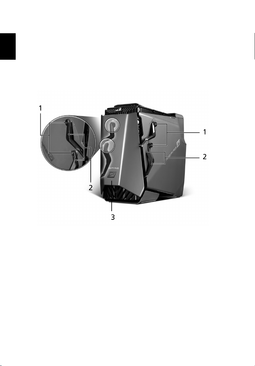
Closed front panel
Page 21

No Component
1 Hinge screws x 4
2 Door hinges x 4
3 Bezel door
9
English
Page 22
English
2 System tour10
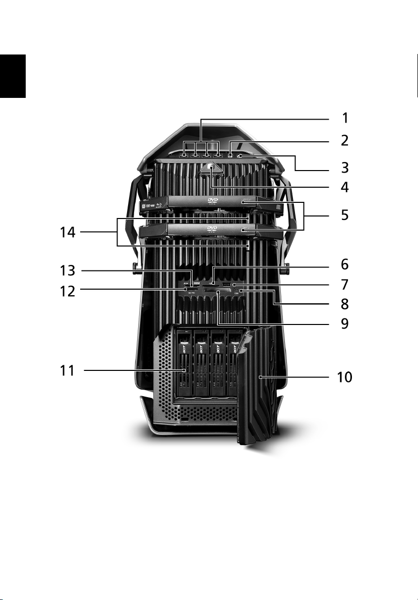
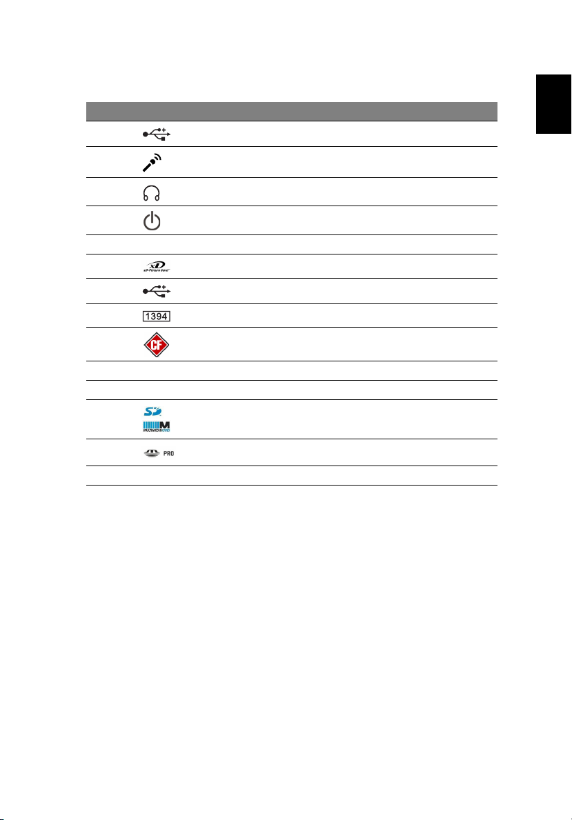
Front panel
Page 23
11
No Icon Component
1 USB 2.0 ports
2 Microphone/line-in jack
3 Headphone/line-out jack
4 Power button/power indicator
5 Optical disk drives
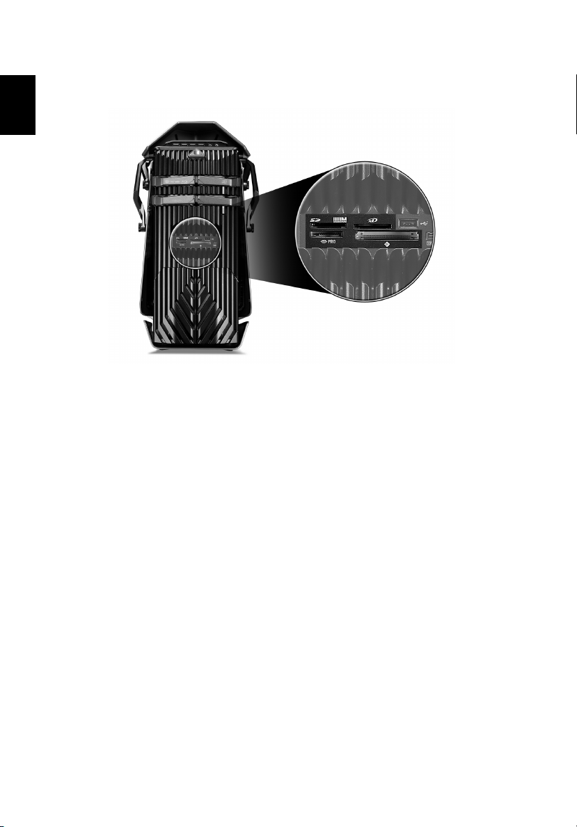
6 XD (eXtreme Digital) slot
7 USB 2.0 port
8 IEEE 1394 port (4-pin)
9 CF I/II (CompactFlash Type I/II) slot
10 Drive bay door
11 Easy-swap hard disk drive (1~4)
12 SD/MMC (SecureDigital/MultimediaCard) slot
13 MS/MS Pro (Memory Stick/Memory Stick Pro Duo) slot
14 Optical disk drive eject buttons
English
Page 24
English
2 System tour12
Using the memory card reader
Your computer supports multi-media card slots.
These slots are useful for transferring data to and from the following memory
cards to your computer.
™
®
™
™
Card
®
(Type I and II)
(SD) Card
™
™
™
™
• CompactFlash
•CF+
™
Microdrive
• MultiMediaCard (MMC)
•MMC
mobile
• Reduced-Size MultiMediaCard (RS-MMC)
•Secure Digital
• miniSD
•xD-Picture Card
• Memory Stick
• Memory Stick PRO
• Memory Stick Duo
• Memory Stick PRO Duo
Memory cards are used in a variety of digital devices such as digital camera,
digital camcorders, handheld game consoles, and mobile phones.
To insert a memory card:
1 Hold the card label-side up with the card facing the computer.
2 Slide the card into the slot until it is seated.
Page 25

13
To remove a memory card:
1 Before ejecting a card:
• Exit the application using the card.
• Left-click on the Safely Remove Hardware icon on the Windows
taskbar and stop the card operation.
2 Gently press the card further into the slot to pop it out.
3 Pull out the card from the slot.
English
Page 26
English
2 System tour14
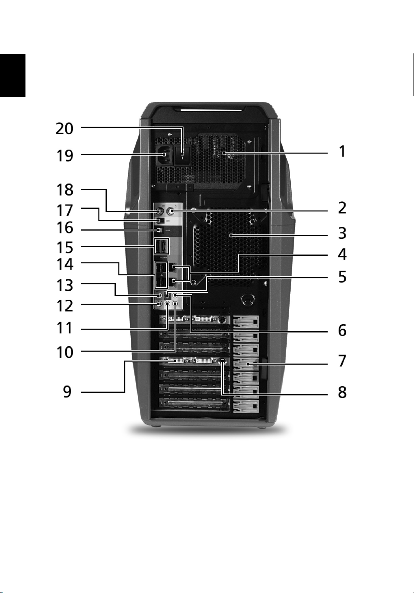
Rear panel
Page 27
No Icon Component
1 Power supply
2 PS/2 mouse port
3 System fan
4 Network ports
5 Rear speaker jack
6 Center speaker/subwoofer jack
7 Expansion slot locks
8 S-video port
9DVI port
10 Audio-in/line-in jack
11 Headphone/line-out/front speaker jack
12 Microphone/line-in jack
15
English
13 Side speaker/line-out jack
14 USB ports
15 eSATA (External Serial Advanced Technology
Attachment) ports
16 CL_CMOS CMOS (Complementary Metal Oxide Semiconductor)
reset button
17 IEEE 1394 port (6-pin)
18 PS/2 keyboard port
19 Power connector
20 Main power switch
Page 28

English
2 System tour16
Internal components
Page 29

No Component
1 Liquid cooling
2 Mainboard
3 System memory
4 Release sliders for optical drives
5 Hard drive backplane board
6 Release sliders for HDD drives
7 Expansion slot lock levers
8 Expansion card
9 System fan
10 Power supply module
17
English
Page 30
System board
2 System tour18
English
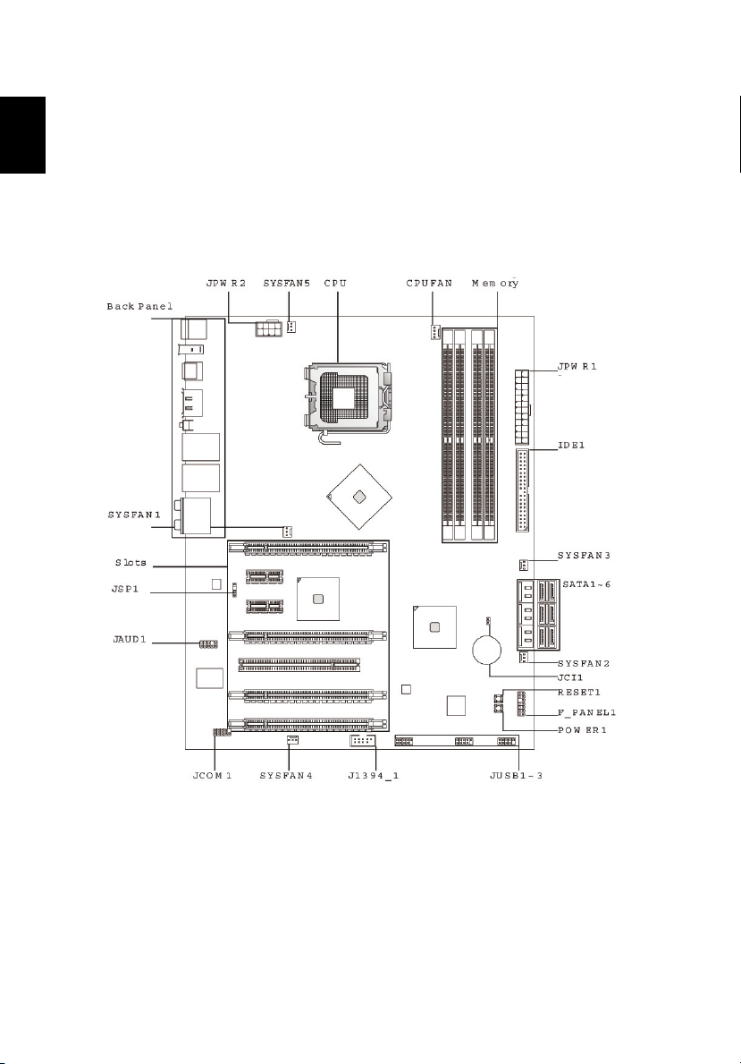
Mainboard
Page 31

19
Code Component
JPWR2 8-pin ATX power connector
SYSFAN5 System fan 5 cable connector
CPU Processor socket
CPUFAN Processor fan cable connector
Memory System memory slots
JPWR1 24-pin ATX power connector
IDE1 IDE cable connector
SYSFAN3 System fan 3 cable connector
SATA1-6 SATA data cable connectors
SYSFAN2 System fan 2 cable connector
JCI1 Chassis intrusion connector
RESET1 Reset button
F PANEL_1 Front panel connector
POWER1 Power button
JUSB1-3 Front USB connectors
J1394_1 IEEE 1394 connector
SYSFAN4 System fan 4 cable connector
JCOM1 Serial port connector
JAUD1 Front panel audio connectors
JSP1 S/PDIF-Out connector
Slots PCI Express x8 slot (PCI_E6)
PCI Express x16 slot (PCI_E5)
PCI 2.3 5V slot (PCI1)
PCI Express x16 expansion slots (supports PCI-E 2.0x
16 speed) (PCI_E1 and PCI_E4)
PCI Express x1 slots (PCI_E2 and PCI_E3)
SYSFAN1 System fan 1 cable connector
English
Page 32

English
2 System tour20
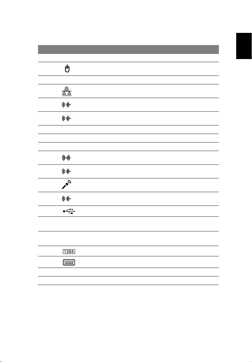
Back panel I/O
Code Color Component
Mouse Green PS/2 mouse port
Keyboard Purple PS/2 keyboard port
1394 port IEEE 1394 port (6-pin)
S/PDIF-out jack USB ports
eSATA ports eSATA ports
Clear CMOS
Button
LAN Jacks Network ports
USB ports USB ports
CS-Out Orange Center speaker/subwoofer jack (in 5.1/7.1
RS-Out Black Rear speaker/surround out jack (in 4/5.1/7.1
SS-Out Gray Side speaker/surround out jack (in 7.1 channel
Line-In Blue Audio-in/line-in/side-surround out jack (in 7.1
Line-Out Green Headphone/line-out/front speaker jack
Mic Pink Microphone/line-in jack
CMOS reset button
channel mode)
channel mode)
mode)
channel mode)
This jack connects to an external CD player, tape
player, or other audio devices.
This jack connects to speakers or headphones.
This jack connects to a microphone.
Page 33

21
Audio card (optional)
No Component
1 S/PDIF line-in jack
2 S/PDIF line-out jack
3 Rear speaker/line-out jack
4 Center speaker/subwoofer/line-out jack
5 Side speaker/line-out jack
6 Front speaker/line-out jack
7 Microphone/line-in jack
8 Front panel header audio connector
9 HDMI (High-Definition Multimedia Interface) header audio connector
English
Page 34

System board switches and
2 System tour22
English
connectors
The System board switches are easy to turn off or reset the computer when user
testing the system.
Power button
Press the power button (POWER1) on the mainboard to turn the system on or
off.
Reset button
Press this reset button (RESET1) on the mainboard to reset the system.
Page 35

23
IDE connector
The IDE1 connector supports IDE hard disk drives, optical disk drives, and other
IDE devices.
Important: If you install two IDE devices on the same cable, you
must configure the drives separately to master / slave mode by
setting jumpers. Refer to IDE device's documentation supplied by
the vendors for jumper setting instructions.
Serial ATA connector: SATA1~6
The six serial ATA connectors (SATA1-6) is a high-speed Serial ATA interface
port. Each connector can connect to one Serial ATA device.
English
Important: Please do not fold the Serial ATA cable into 90-degree angle.
Otherwise, data loss may occur during transmission.
Page 36

English
2 System tour24
Fan power connectors
The fan power connectors (CPUFAN and SYSFAN1-5) support system cooling fan
with +12V. When connecting the wire to the connectors, always note that the
red wire is the positive and should be connected to the +12V; the black wire is
ground and should be connected to GND.
Important: CPUFAN supports fan control. You can install Dual Core Center
utility that will automatically control the these fan speed according to the
actual CPU and system temperature. Fan/heat sink with 3 or 4 pins are both
available for CPUFAN.
Front panel connectors
The front panel connectors (F_PANEL1) are for electrical connection to the front
panel switches and LEDs.
F_PANEL1 front panel pin definition
PIN SIGNAL DESCRIPTION
1 Storage_LED + Hard disk LED pull-up
2 FP PWR/SLP MSG LED pull-up
3 Storage_LED - Hard disk active LED
4 FP PWR/SLP MSG LED pull-up
5 RST_SW - Reset Switch low reference pull-down to GND
6 PWR_SW+ Power Switch high reference pull-down to GND
Page 37

25
PIN SIGNAL DESCRIPTION
7 RST_SW + Reset Switch high reference pull-up
8 PWR_SW- Power Switch low reference pull-up
9 RSVD_DNU Reserved. Do not use
10 None No pin
12 LAN_LED+ LAN LED pull-up
14 LAN_LED- LAN LED pull-up
Serial port connector
The serial port connector (JCOM1) is a 16550A high speed communication port
that sends/receives 16 bytes FIFOs and connects to a serial device.
Serial port pin definition
Pin Signal Description
1 DCD Data Carry Detect
2 SIN Serial In or Receive Data
3 SOUT Serial Out or Transmit Data
4 DTR Data Terminal Ready
5 GND Ground
6 DSR Data Set Ready
7 RTS Request To Send
8 CTS Clear To Send
9 RI Ring Indicate
English
Page 38

System LED indicators
2 System tour26
English
Front and rear panel LED indicators
Indicator Location Color Status Description
Power Front panel
(Power
button)
HDD Front panel
(Easy-swap
HDD)
Network
activity
Network link Rear panel
Rear panel
(Network
port)
(Network
port)
Blue On System has AC power
and is powered on
Blinking System is in standby
mode
Green Blinking Ongoing HDD activity
Amber On Easy-swap HDD failure
Green/
Amber
Orange Off Off-line network
Green Off 10 Mbps link network
Orange On 1000 Mbps link
Flashing HDD is rebuilding
On Active network link
Blinking Ongoing network data
activity.
access
On 100 Mbps link network
access
network access
Page 39

27
Mainboard LED indicators
The mainboard LED indicators are easy to check the system status when user
open the cover or testing the system board...
English
Indicator Status
PCIE1 (blue) Lights when PCI E1 slot is functional.
PCIE2 (blue) Lights when PCI E2 slot is functional.
PCIE3 (blue) Lights when PCI E3 slot is functional.
PCIE4 (blue) Lights when PCI E4 slot is functional.
PCI (blue) Lights when PCI1 slot is functional.
PCIE5 (blue) Lights when PCI E5 slot is functional.
PCIE6 (blue) Lights when PCI E6 slot is functional.
DIMM1 (orange) Lights when the DIMM1 slot is functional.
DIMM2 (green) Lights when the DIMM2 slot is functional.
DIMM3 (green) Lights when the DIMM3 slot is functional.
DIMM4 (orange) Lights when the DIMM4 slot is functional.
HDD (pink) Lights when the HDD is functional.
Page 40

English
2 System tour28
Indicator Status
Power (blue) Lights when the system is powered on.
Standby (pink) Lights when the system is in standby mode.
Page 41

3 Setting up your
computer
Page 42

3 Setting up your computer30
Arranging a comfortable work area
English
Working safely and comfortably begins with the arrangement of your work
space and the proper use of equipment. For this reason, it is very important to
take time and think about how you are going to arrange your work area. Refer
to the diagram on the following page as you set up your system.
Here are some points to consider:
Adjusting your chair
Having the right kind of chair does not necessarily mean you'll be properly
supported. It is necessary to adjust your chair to fit your body. Proper body
posture will make you more comfortable and productive.
• Avoid tilting your chair. If you have a chair that tilts, lock the tilt knobs so
that your chair will not tilt forward or backward while you are using your
computer.
• Adjust your chair height in such a way that you can sit on it with your
thighs parallel to the floor and your feet resting flat on the floor.
• Rest your body on the chair back. Your torso works harder to maintain
balance if you do not rest your body on the chair back.
Positioning your PC
Page 43

31
Take note of the following when selecting a location for your computer:
• Do not put your computer near any equipment that might cause
electromagnetic or radio frequency interference, such as radio
transmitters, televisions, copy machines or heating and air-conditioning
equipment.
• Avoid dusty areas and extremes of temperature and humidity.
• You may place your computer beside your desk or under your table, as
long as it does not block the space you need for working and moving.
Positioning your monitor
Place your monitor at a comfortable viewing distance, usually 50 to 60 cm away.
Adjust the display in such a way that the top of the screen is at or slightly below
eye level.
Positioning your keyboard
The location of the keyboard is a very important factor for your posture.
Placing it too far away will make your body lean forward, forcing you to sit
in an unnatural position. Placing it too high will add tension to your
shoulder muscles.
• The keyboard should be placed just above your lap. Adjust the keyboard
height by flipping the folding stands located under the keyboard.
• Keep your lower arms parallel to the floor as you type. Your upper arms
and shoulders should be relaxed. Then try typing with a light touch. If you
feel any shoulder or neck strain, stop for a while and check your posture.
• Position your keyboard in front of your monitor. Putting your keyboard
beside your monitor will make you turn your head while you type which
could add tension to your neck muscles.
English
Positioning your mouse
• The mouse should be placed on the same surface as your keyboard so that
you can reach it with ease.
• Adjust its position to allow enough space for movement without making
you stretch or lean over.
• Use your arm to move the mouse. Do not rest your wrist on the table when
moving the mouse.
Page 44

3 Setting up your computer32
Connecting the computer
English
Setting up your computer is easy. For the most part, you only have four things
to connect: the mouse, the keyboard, the monitor, and the power cable.
Note: The peripherals shown in the connections below are
for your reference only. Actual device models may vary in
select countries.
Connect your mouse and keyboard
PS/2 interface
Plug the PS/2 mouse and keyboard cable into the PS/2 keyboard port (purple
port) and mouse port (green port) located on the rear panel of your computer.
USB interface
You can also plug a USB mouse or a USB keyboard cable into any of the USB
ports located on the front and rear panels of your computer.
Page 45

33
Connect a monitor
To connect a monitor, simply plug the monitor cable into the DVI port
located on the rear panel of your computer. If you have a monitor that supports
S-video, plug the monitor cable to the S-video port located on the rear panel of
your computer.
English
Note: Refer to the monitor manual for additional instructions
and information.
Page 46

English
3 Setting up your computer34
Connect to a broadband network
The two Gigabit Ethernet ports on the rear of the computer can be used individually,
combined, or configured in a number of ways depending on your needs. With the system’s
onboard NVIDIA nForce chipset and DualNet technology, you can combine the two
network ports to work as one. It also allows your computer to serve as a home gateway and
it provides advanced networking features including teaming, load balancing, fail-over, and
TCP/IP acceleration.
Individual network configuration
Connect one end of the network cable on the network port on the rear of the
computer, then connect the other end of the network cable into the cable
modem or network jack or hub on your network.
Note: Consult your network system administrator or operating system
manual for information on how to configure your network setup.
Installing the WLAN antenna
(optional)
Locate an unused PCI slot and place the card on top. Gently push card down
into the slot. When the card is correctly in position, screw the card securely on
to the case.
1 Install antenna to the system by fastening the threaded end of the antenna into the
WLAN antenna connector on the rear panel of the system.
Page 47

35
2 Rotate the antenna clockwise until tight.
3 Flip up the antenna.
Combined network configuration
One way sharing an Internet connection is connecting a video game console to
your computer. See page 56 for more information.
Note: Refer to the documentation that came with your video game console
for detailed connection and configuration information.
Connect to power
Caution: Before you proceed, check the voltage range in your area. Make
sure that it matches your computer's voltage setting. If they don't match,
change your computer's voltage setting according to your area's voltage
range.
1 Plug the power cable into the power cable socket located on the rear panel
of your computer.
English
2 Plug the other end of the power cable into a power outlet.
Page 48

3 Setting up your computer36
Turning on your computer
English
After making sure that you have properly set up the system, applied power, and
connected all the necessary peripherals, you can now power on the system.
Follow the procedure below.
1 Turn on the main power switch located on the rear of the computer.
Page 49

37
2 Press the power button.
Important: Make sure that the power cable is properly plugged into an
electrical outlet. If you are using a power strip or an AVR (Auto-Voltage
Regulator), make sure that it is plugged in and turned on.
English
Page 50

3 Setting up your computer38
Turning off your computer
English
The software procedure below applies to system running a Windows OS. For
other OS shutdown procedures, refer to the related user documentation.
1 On the Windows Vista taskbar, click on the Start button, and click ,
then click Shut Down.
2 Turn off all peripherals connected to your computer.
If you cannot shut down your computer normally, press and hold the power
button for at least four seconds. Quickly pressing the button may put the
computer in suspend mode only.
Page 51

4 Using your
desktop
Page 52

Using the keyboard
4 Using your desktop40
English
The gaming keyboard has several types of keys and buttons. It features bluebacklit characters on every key, 18 programmable G keys, convenient media
control buttons, Macro button, separate cursor keys, and 12 function keys that
takes care of your everyday keyboarding and gaming requirements.
1
12
11
10
No. Item Description
1 USB ports Plug USB gaming devices to these ports.
2 Multimedia keys Allow you to conveniently play, pause, stop,
advance or rewind a song or movie using your
keyboard.
A volume control dial allows you to increase or
decrease the volume.
3 Backlight key Toggles the backlight key on or off.
4 Indicators Show if the Num Lock, Caps Lock, or Scroll lock
keys are activated. Press the corresponding keys
to activate the function.
5 Function keys
(F1 - F12)
6 Numeric keypad Press these keys to type numbers when Num
7 Cursor keys Also called the arrow keys, let you move the
8 Application/Shortcut
key
Lets you perform specific functions, depending
on the application that uses them.
Lock is turned on.
cursor around the screen. They serve the same
function as the arrow keys on the numeric
keypad when the Num Lock is toggled off.
This key has the same effect as clicking the right
mouse button; it opens the application's
context menu.
2
3
4
5
6
7
89
Page 53

41
No. Item Description
9 Windows logo
key
10 Programmable
G keys
11 Macro keys Creates and saves new macros while playing a
12 Game mode switch Puts the keyboard in normal computer or
Pressed alone, this key has the same effect as
clicking on the Windows Start button; it
launches the Start menu. It can also be used
with other keys to provide a variety of
functions:
• < > + <Tab> — Activates the next
Taskbar button.
• < > + <E> — Opens the My Computer
window.
• < > + <F1> — Opens Help and Support.
• < > + <F> — Opens the Find: All Files
dialogue box.
•< > + <R> — Opens the Run dialogue
box.
• < > + <M> — Minimizes all windows.
• <Shift> + < > + <M> — Undoes the
minimize all windows action.
Execute complex macros with a single keypress.
Allows you to set 54 custom programmed keys
per game.
game.
gaming mode.
When in gaming mode, the Start and
Application/Shortcut keys are disabled. All
other keys in the keyboard will function
normally.
When in normal mode, the Start and
Application/Shortcut keys are enabled.
English
For more information on how to use the Logitech G11 keyboard, refer to the
Logitech help files.
Page 54

Using the mouse
4 Using your desktop42
English
The mouse controls the pointer movement on the computer display.
No. Item Description
1 Tilt wheel Push wheel to either side to scroll horizontally.
Program wheel to mimic keyboard commands.
2 In-game dpi
increase
3 In-game dpi
decrease
4
5 Programmable
6 Programmable
dpi LEDs
side buttons
left and right
mouse buttons
1
Press button to increase dpi (tracking sensitivity).
Press button to decrease dpi (tracking sensitivity).
Activated by dpi buttons.
Launch Logitech SetPoint
Launch Logitech SetPoint
and tilt wheel assignments.
2
to customize button
2
to customise button
1 The dpi LEDs show dpi settings of mouse when dpi buttons are used. For more
information about the dpi LEDs refer to the documentation that came with the
mouse.
2 Refer to the software help system to learn more about the SetPoint software.
For more information on how to use the gaming mouse, refer to the Logitech
help files.
Page 55

43
Using the optical drive
Your computer may come with a Blu-ray/HD reader + SuperMulti burner. This
drive is located on the front panel of your computer. The BD and HD drive
allows you to play not only old CD-ROMs, CD-I disks, and video CDs, DVD-RAM/RW, DVD-ROMs, DVD+R/-R disks, but play BD disks and HD DVD disk as well.
CDs, DVDs, BDs, HD DVDs are also compact, lightweight and easy to carry
around. However, they are more delicate and must be handled with extra care.
To insert a disk into your computer's optical drive:
1. Press the optical drive’s eject button located on the front panel.
English
Page 56

English
4 Using your desktop44
2. When the disk tray slides open, place the disk gently on the tray. Make
sure that the label or title side of the disk is facing upward.
When holding a disk, hold it by the edges to avoid leaving smudges
or fingerprints.
3. Push the tray and it will close automatically or press the eject/load button.
Taking care of your optical disks
• Keep your disk in its case when not in use to avoid scratches or other
damage. Any kind of dirt or damage can affect the data on the disk, impair
the disk lens reader on the optical drive, or stop the computer from
successfully reading the disk.
• When handling disks, always hold them by the edges to avoid smudges
or fingerprints.
• When cleaning disks, use a clean, dust-free cloth and wipe in a straight line
from the center to the edge. Do not wipe in a circular motion.
• Clean you optical drive periodically with a cleaning kit; cleaning kits may
be purchased at any computer or electronics shop.
Page 57

45
Connecting options
Your computer offers excellent expansion capabilities with its built-in ports and
connectors. This section describes how to make connections through various
options. When connecting peripherals, read the manual included with the
peripheral for operating instructions.
Printer
You can connect a USB printer to an available USB port . See your printer
manual for operating instructions.
IEEE 1394 devices
You can connect IEEE 1394 supported devices like a digital video camera,
external storage devices, or external optical drives to the 4-pin and 6-pin fast
IEEE 1394 located on the front and rear panel of your computer.
English
Page 58

English
4 Using your desktop46
eSATA devices
The computer’s eSATA (External Serial ATA) port allows you to connect
external SATA device.
Audio devices
Note: The audio devices shown below are for reference only. Actual device
models may vary in select countries.
Audio devices are easy to connect with the audio ports accessible from the front
and rear of the computer.
• Microphone — Plug an external microphone (or an audio line-in device)
into the microphone/line-in jack (pink jack) located on the front and rear
of the computer.
• Amplified stereo speakers, headset, or heaphone — Plug amplified
speakers, headset, or headphone to the headphone/line-out/front speaker
Page 59

47
jack (green jack) located on the front and rear of the computer.
English
Page 60

English
4 Using your desktop48
• Analog speaker system — You can connect the front left and right speaker
to the headphone/line-out/front speaker jack (green jack), center speaker
or subwoofer to the center speaker/subwoofer jack (orange jack), rear left
and right speaker to the rear speaker jack (black jack), and side left and
right speaker to the side speaker/line-out jack (gray jack).
Page 61

49
Refer to the table below for different channel speaker setup.
Audio ports
Speaker
system
1.1XXX O O
2.1XXO X O
4.1OOX X O
5.1 X O O X O
7.1OOX X O
Side
speaker/
line-out
(Gray)
O - Denotes an audio device connection to an audio jack
X - Denotes no connection made
Rear
speaker
(Black)
Center
speaker/
subwoofer
(Orange)
Microphone
/line-in
(Pink)
Headphone
/line-out/
front
speaker
(Green)
English
Page 62

English
4 Using your desktop50
Audio devices to an optional audio card
The optional Sound Blaster X-Fi 2 audio card allows you to connect a wide
variety of audio devices and speaker system transforming your computer into
entertainment center. You can also enjoy digital audio surround sound with
Dolby Digital Live in your games, music, and movies.
Note: The audio devices shown below are for reference only. Actual device
models may vary in select countries.
• Headphone — Plug the headphone to the front speaker/line-out jack
(green jack).
• Headset — Plug the headset to the speaker/line-out jack (green jack) (1)
and the microphone/line-out jack (blue jack) (2) located on the front and
rear of the computer.
Page 63

51
• Digital speakers — Plug one end of the optical cable (2) to the S/PDIF lineout jack cable on the audio card (1) then plug the other end of the optical
cable to the S/PDIF line-out jack on the digital speaker (3).
• Analog speaker system
The audio card supports analog systems up to 7.1 channels. To learn more
about different channel speaker systems, consult the following sections.
• 2.1 channel analog speakers
(1) Plug one end of the 2 channel audio cable (2) to the front
speaker/line-out jack (green jack) (1)
(2) Plug the other end of the audio cable (2) to the audio input jack
on the analog speaker (3).
English
Page 64

English
4 Using your desktop52
• 4.1 channel analog speakers
(1) Plug the gray end of the 4 channel audio cable (3) to the rear
speaker/line-out jack (gray jack) (1) then plug the other end of
the audio cable to the rear (audio input) jack on the analog
speaker (5).
(2) Plug the green end of the audio cable (3) to the front speaker/
line-out jack (green jack) (2) then plug the other end of the audio
cable to the front (audio input) jack on the analog speaker (4).
Page 65

53
• 5.1 channel analog speakers
(1) Plug the gray end of the 5.1 channel audio cable (4) to the rear
speaker/line-out jack (gray jack) (1) then plug the other end of
the audio cable to the rear (audio input) jack on the analog
speaker (7).
(2) Plug the orange end of the audio cable (4) to the center speaker/
subwoofer/line-out jack (orange jack) (2) then plug the other end
of the audio cable to the center/subwoofer (audio input) jack on
the analog speaker (5).
(3) Plug the green end of the audio cable (4) to the front speaker/
line-out jack (green jack) (3) then plug the other end of the audio
cable to the front (audio input) jack on the analog speaker (6).
English
Page 66

English
4 Using your desktop54
• 7.1 channel analog speakers
(1) Plug the gray end of the 7.1 channel audio cable (5) to the rear
speaker/line-out jack (gray jack) (1) then plug the other end of
the audio cable to the rear (audio input) jack on the analog
speaker (8).
(2) Plug the orange end of the audio cable (5) to the center speaker/
subwoofer/line-out jack (orange jack) (2) then plug the other end
of the audio cable to the center/subwoofer (audio input) jack on
the analog speaker (6).
(3) Plug the gray end of the audio cable (5) to the side speaker/line-
out jack (green jack) (3) then plug the other end of the audio
cable to the side (audio input) jack on the analog speaker (9).
(4) Plug the green end of the audio cable (5) to the front speaker/
line-out jack (green jack) (4) then plug the other end of the audio
cable to the front (audio input) jack on the analog speaker (7).
Page 67

55
USB devices
Universal Serial Bus (USB) is a serial bus design capable of cascading peripherals
such as a digital camera, keyboard, mouse, scanner, printer, modem, flash
drives, VoIP phones, and gaming devices (such as joystick, steering wheels,
rumble pads, or foot pedals). With USB, complex cable connections can be
eliminated.
Your computer comes with several external USB ports: one on the multi-media
card slot, four on the front and four on the rear panel. These ports support USB
2.0 high-performance external devices such as webcams and digital still
cameras. They also allow you to connect additional USB devices to your
computer without using up its resources.
To connect a USB device, simply plug the device cable into any of the USB ports
located on the front and rear panels of your computer.
English
Note: The USB devices shown below are for reference only. Actual device
models may vary by geographic region.
Note: Some USB devices have a built-in USB port which permits you to
connect more USB devices.
Page 68

English
4 Using your desktop56
Connecting a video game console
The computer’s DualNet feature allows you to use your computer as a router
and share Internet connection with a video game console, such as an Xbox
console.
To connect and share Internet connection with a video game
console:
1. Before connecting any cables, turn off your computer and video game
console.
2. Connect the computer to the network. See page 34 for detailed
instructions.
3. Connect one end of the network cable on the network port on the rear of
the computer, then connect the other end of the network cable to the
network jack on the rear of the video game console.
4. Turn on your computer.
5. Configure the Windows ICS (Internet Connection Sharing) to share your
Internet connection. Refer to the help documentation of your operating
system for more information.
Note: Refer to the documentation that came with your video game console
for detailed connection and configuration information.
Page 69

5 Advanced
hardware
setup
Page 70

5 Advanced hardware setup58
Video card configuration
English
When you have two identical graphics cards supporting NVIDIA SLI® (Scalable
Link Interface) technology installed in your computer, you can set the SLI
configuration to share the workload between the two graphic cards when
rendering a 3D scene.
This section includes procedures for setting up video cards to support SLI
Antialiasing, SLI technology, and multiple displays.
Enabling SLI Antialiasing
SLI Antialiasing is a standalone rendering mode that doubles anti-aliasing
performance by splitting the workload between two graphic cards, offering
superior picture quality. When SLI Antialiasing is enabled, it offers two new anti
aliasing settings: SL18x and SL16x.
To enable SLI Antialiasing:
1 Open the NVIDIA Control Panel by right-clicking on the desktop and
selecting NVIDIA Control Panel.
2Select 3D Settings.
Page 71

59
3Select Manage 3D settings.
4 Click on Antialiasing settings and select your desired mode.
English
5 Click Apply.
Note: Remember, when you use one of the SLI Antialiasing modes, your SLI
performance mode will no longer be active. The modes cannot be applied
together.
Page 72

5 Advanced hardware setup60
Setting up an SLI configuration
English
To enable the SLI technology:
1 When you reboot the computer after installing the SLI components, you
will be greeted with a "pop up" bubble in the lower right hand corner,
telling you that you have an SLI-enabled PC.
2 Click on the SLI capable system message to open the following window.
1
1
2 Select the Enable SLI technology checkbox, then click Apply.
Note: Currently, SLI technology does supports one display when enabled. If
you have multiple displays and wish to use more than 1 display, you will
need to disable SLI technology in the same desktop properties menu. You
can enable SLI technology at any time, but note that you will only be able
to power 1 display when enabled.
You can also access the Set SLI Configuration page by opening the NVIDIA
Control Panel. Perform steps 1 through 3 of the "Enabling SLI Antialiasing" on
page 58.
Page 73

61
Setting up multiple monitors
To enable, disable, or configure multiple-monitor support:
Note: Before you can enable an additional monitor, make sure the monitor
is connected to your system’s video card and powered on.
1 Open Display Properties.
• Right-click an empty area of the desktop and select Properties.
• Click Start > Control Panel > Display icon.
2 Click the Settings tab to display the multiple -monitor configuration dialog
box.
3 Enable the secondary monitor.
a Click on the Monitor icon or click the Display drop-down menu to
select the monitor.
b Click the Extend my Windows desktop onto this monitor check box.
4 Select a primary monitor.
By default, the first monitor is recognized by Windows OS as the primary
monitor. If you want to set a different monitor as a primary, click the “Use
this device as the primary monitor” check box.
If you change your primary monitor, you might want to drag the monitor
icons to match the physical layout of the new primary/secondary monitor
assignments.
5 Click OK.
English
Page 74

5 Advanced hardware setup62
Setting up the multichannel audio
English
output
(optional)
Select the correct speaker setup option in the Creative® Media Source utility to
get the best audio experience.
To select the correct speaker setup to support multichannel audio:
1 Launch Creative Media Source Go by performing either of the following:
• Double-click on the Creative volume control audio icon on the system
tray.
• Move the mouse cursor on top of screen. The Creative MediaSource
Go quick start bar appears on the desktop.
2 Click the Entertainment Mode icon.
3 Click the Speaker button.
4 In the Speakers and Headphone
speaker system.
5 Exit the application.
For more information and usage details of the Creative Media Source Go utility,
refer to its online help.
drop-down menu, select the type of your
Page 75

63
Setting up RAID
RAID technology uses multiple drives to either increase total disk space or to
offer data protection. RAID techniques are divided into different levels and it
optimizes storage solutions by using multiple disks grouped together and
treating them as single storage resource. With NVIDIA MediaShield storage
technology you can easily set up and configure the SATA drives for even higher
performance and security.
RAID arrays
NVIDIA MediaShield supports the following types of RAID arrays:
• RAID 0 (Stripe): Defines a disk striping scheme that improves the disk read
and write times for many applications. Data is split up across all the drives,
delivering unmatched storage performance and capability.
English
• RAID 1 (Mirror) : Defines techniques for mirroring data. Data is stored
twice on both the data disk and mirror disk.
Page 76

English
5 Advanced hardware setup64
• RAID 5 : Defines techniques for parity data. Data is striped and parity is
distributed across three or more drives, improving disk performance and
fault tolerance.
• RAID 0+1 : Combines RAID 0 and RAID 1 in a single system with disk
striping for optimized performance and disk mirroring for fault tolerance.
RAID 0 RAID 1
Enabling RAID
The RAID feature must be enabled in the BIOS before you can configure RAID.
To enable RAID:
1 Reboot your computer.
2 Press the Delete key to enter the BIOS setup.
Page 77

65
3 Use the arrow keys to select Integrated Peripherals, then press Enter.
4Select On-Chip ATA Devices, then Enter.
English
5Select RAID Mode, then press RAID.
6 Use the arrow keys to select Enabled option for each SATA port.
Page 78

English
5 Advanced hardware setup66
7 Press F10 to save the configuration and exit.
Creating a RAID array
You can use RAID BIOS or the MediaShield utility to create the following types
of RAID array.
• Non-bootable array
This is the standard method of using non bootable disks in a RAID array.
•Bootable array
You can configure a RAID array and then install the OS over it.
To create a non-bootable RAID array using RAID BIOS:
1 Enable RAID in the system BIOS. See page 64.
2 After rebooting the system, wait until you see the RAID software
prompting you to press F10.
The RAID prompt appears as part of the system POST and boot process
prior to loading of the OS. You have a few seconds to press F10 before the
prompt disappears.
3 Press F10 to save the configuration and exit.
4 Create the RAID array.
Note: If you have not already created a RAID array, the Define a New Array
screen appears. By default, RAID mode is set to Mirroring and Stripe Block is
set to Optimal.
If you have already created a RAID array, the MediaShield BIOS- Array List
screen appears, listing the arrays in the system. Press N to go to the
MediaShield BIOS- Define a New Array screen.
Page 79

67
a In the RAID Mode box, select the mode you want — either Mirroring,
Stripe, Spanning, Stripe Mirroring, or RAID 5.
b In the Stripe Block
box, enter the stripe block size. It is recommended
to leave this value at the default Optimal, which is 64 KB, but the
values can be between 4 KB and 128 KB (4, 8, 16, 32, 64, 128 KB).
Note: Stripe block size selection is not available for Mirroring or Spanning
RAID arrays.
c In the Free Disks section, select a disk and click the arrow key to move
it to the Array Disks section.
d Continue until all disks that you want to use as RAID array appear in
the Array Disks section.
English
e Press F7.
Page 80

English
5 Advanced hardware setup68
f Press Y to clear the disk data.
g Press Y to clear MBR (Master Boot Record).
The Array List screen appears, where you can review the RAID arrays
that you have set up.
h Press F10 to save the configuration and exit.
Page 81

69
5 Initialize the RAID array.
After creating the array, reboot the computer and then initialize the newly
created array under Windows as follows:
a Launch Computer Management by clicking Start > Control Panel >
Administrative Tools > Computer Management.
b Click Disk Management.
Under Windows Vista, the Initialize Disk dialog box appears, follow
the instructions on the dialog box to initialize your disk.
English
6 Format the unallocated disk space.
Page 82

English
5 Advanced hardware setup70
For additional information on initializing, partitioning, and formatting the
newly created array, refer to the section on Disk Management in your
system’s Help and Support Center.
To create a non-bootable RAID array using MediaShield:
1 Enable RAID in the system BIOS. See page 64.
2 Create the RAID array.
a Install the NVIDIA RAID drivers.
Page 83

71
(1) Start the nForce Setup program to open the NVIDIA Windows
nForce Drivers page.
(2) Select the modules you want to install, then follow the onscreen
instructions to finish installation.
b Open the NVIDIA Control Panel by right-clicking on the desktop and
selecting NVIDIA Control Panel.
c From the Select a Task
array to start the Create Array Wizard and follow the onscreen
instructions to complete disk array creation.
Press F1 to access the online help for more information on array
creation process.
3 Perform steps 5 and 6 of the “To create a non-bootable RAID array using
the RAID BIOS” section.
pane under the Storage category, select Create
English
To create a bootable RAID array using RAID BIOS:
1 Perform steps 1 through 4 of the “To create a non-bootable RAID array
using the RAID BIOS” section.
2 Create a bootable array.
a Use the arrow keys to select the array that you want to set up as a
bootable disk.
b Press B to specify the array as bootable.
c Press Enter to view and verify details for the selected array.
The Array Detail screen shows various information about the array
that you selected, such as Stripe block, RAID mode, Stripe width, Disk
model name, and Disk capacity.
From the Array Detail screen, you can do the following:
Page 84

English
5 Advanced hardware setup72
• Rebuild the array - Press R then use the arrow keys to select the
disk to rebuild and then press F7.
• Delete the array - Press D then press Y at the prompt.
• Clear the MBR - Press C then press Y at the prompt.
• Remove the volume - Press V, then use the arrow keys to select
the disk volume to remove and then press F7.
For Mirroring (RAID 1), single-disk Stripe (RAID 0), and single-disk
Spanning arrays, removing a volume is a way to remove a disk
from an array and convert it to a basic disk without deleting any
data. In Mirroring array, the array becomes degraded (if there
are still disks in the array) and must be rebuilt.
The Remove Vol option is not available with systems that do not
support NVIDIA’s RAID pass-through disk management.
d Press Enter to go back to the previous screen.
e Press F10 to save the configuration and exit.
3 Install the RAID drivers. See page 72.
4 Initialize the RAID array. Perform step 5 of the “To create a non-bootable
RAID array using the RAID BIOS” section.
Installing the RAID drivers
To install a RAID driver under Windows Vista:
1 After you complete the RAID BIOS setup, boot from the Windows CD.
2 Click Install Now then continue the installation process until you get to the
Which type of installation do you want screen.
3 Click Custom (advanced).
4 Click Load Driver.
5 At the Load Driver
containing the installation files.
6Select NVIDIA nForce RAID Controller, then click Next.
7 Click Load Driver.
8 At the Load Driver
containing the installation files.
9Select NVIDIA nForce Serial ATA Controller, then click Next.
dialog box, click Browse then navigate to the folder
dialog box, click Browse then navigate to the folder
Note: You do not need to install the nForce RAID Device. Windows handles
it automatically as part of the RAID and SATA controller installation process.
Page 85

73
10 Select the disk where you want to install Windows and follow all onscreen
instructions to complete installation.
Important: After Windows Vista is completely installed, it is recommended
to install the nForceWare software in order to access the MediaShield
Storage interface.
For more information on how to use NVIDIA MediaShield, refer to its online
help.
English
Page 86

Overclocking the CPU
5 Advanced hardware setup74
English
An overclocking option is available for manually changing CPU clock speed and
memory clock speed.
Important: Your system is designed to support overclocking. However,
make sure your components are able to tolerate an abnormal setting, while
doing overclocking. Any attempt to operate beyond product specifications
is not recommended. Overclocking may result in system instability.
To manually change the clock speed of your CPU:
1 Reboot your computer.
2 Press Delete to enter the BIOS setup.
3 Use the arrow keys to select Frequency Control, then press Enter.
4 Use the arrow keys to set the System Clock Mode to Manual, then press
Enter.
5 Use the arrow keys to select FSB Clock, then press Enter.
Page 87

75
6 Use the arrow keys to select the value overclocking, then press Enter.
7 Press F10 to save the configuration and exit.
Note: You can also use NVIDIA nTune to overclock your system. To launch
NVIDIA nTune, click Start > All Programs > NVIDIA Control Panel >
Performance. Refer to the online help for more information.
English
Page 88

5 Advanced hardware setup76
Clearing the CMOS settings
English
The onboard CMOS RAM stores the system configuration data and has an
onboard battery power supply. The CMOS RAM records the correct time and
setting of the system hardware configuration. If you want to clear the system
configuration data, such as power-on password or the setup password from the
CMOS RAM, do the following.
1 On the rear panel of your computer, locate the CMOS reset button.
2 Press the CMOS reset button.
3 Reboot the computer and run the Setup utility to reconfigure the system.
Page 89

77
Adjusting event logging and monitoring settings
Use NVIDIA monitor to monitor and log system events. NVIDIA can display
dynamic graphs that track various performance usage and temperatures, and
the voltages, fan speeds, and bus speeds for various system hardware
components.
To adjust the event logging settings:
1 Launch NVIDIA Monitor.
From the Windows desktop, click Start > All Programs > NVIDIA
Corporation > NVIDIA Monitor.
2 Right-click the NVIDIA Monitor then select Settings.
3 On the left pane, select Event Log.
4 Under the Update log file
for tracking selections.
5 Under the Set maximum file size to
maximum file length of the log file settings.
NVMonitor starts a new log file when the maximum file length of the
current log file is reached.
6 Under Log these events
track — profile changes, bus speeds, and temperature.
7 Click Apply.
every drop-down menu, specify the time interval
drop-down menu, specify the
, check one or more of the items that you want to
English
To launch the event logger:
1 Launch NVIDIA Monitor.
2 Right-click the NVIDIA Monitor then select Start event logging.
To view a log file:
1 Launch NVIDIA Monitor.
2 Right-click the NVIDIA Monitor then select View event log.
To adjust the NVIDIA monitoring settings:
1 Launch NVIDIA Monitor.
From the Windows desktop, click Start > All Programs > NVIDIA
Corporation > NVIDIA Monitor.
2 Right-click the NVIDIA Monitor then select Settings.
3 On the Update monitor display every
utility will update the temperature values.
drop-down list, specify how often the
Page 90

English
5 Advanced hardware setup78
Note: Because of SMI traffic and CPU utilization, faster polling times may
impact performance. This may be particularly noticeable when playing WAV
files.
4 Select the Always on top check box if you want to display NVIDIA monitor
application in the foreground while running other tasks.
5 Move the Transparency level
slider to adjust the transparency of the
NVIDIA Monitor window.
6 Choose which temperature scale to use - Celsius or Fahrenheit.
7 Select the check boxes of the components that you want to track - CPU,
System, and chipset temperatures. If unavailable, the check box is grayed-
out.
8 Specify how the system alerts you when a measured temperature exceeds
the limit specified in the BIOS - either with a visual or audio alert.
9 Click Apply.
Page 91

79
System tuning
The NVIDIA tuning engine lets you tune the system using NVIDIA developed
benchmarks to determine the current performance level of the system. You can
also tune the system to various performance criteria. The tuning takes effect
during the current Windows session only. To use the tuned settings in future
Windows sessions, you can create a profile.
Note: Close all applications and save all work before performing any
benchmarking tests or tuning processes.
To tune your system:
1 Open the NVIDIA Control Panel by right-clicking on the desktop and
selecting NVIDIA Control Panel.
2 From the Select a Category
3 Select a tuning type.
4 Click Tune.
During the course of tuning, the system may stop responding or reboot.
NVIDIA recommends checking Automatically continue at reboot ... to
disable prompts on reboot during the tuning process.
A progress bar shows the tuning progress. You can cancel at any time by
clicking Stop.
The tuning results appear in the Results box as a text description of the
number of passes and adjustments made. To view a graph of the results,
click Graph View.
The effects of the tuning apply to the current Windows session only.
5 To use the tuned settings in another Windows session, do the following:
a Click Save to save the tuned settings in a profile.
b When needed, click Load to load the tuned settings.
Options available to customize tuning process, refer to the NVIDIA nTune
online help.
page, click Performance.
English
Page 92

5 Advanced hardware setup80
Acer Empowering Technology
English
The Empowering Technology toolbar makes it easy for you to access frequently
used functions and manage your new Acer system. Displayed by default in the
upper half of your screen, it provides access to the following utility:
Acer eRecovery Management backs up and recovers data flexibly, reliably
and completely.
For more information, right click on the Empowering Technology toolbar, then
select the Help or Tutorial function.
Empowering Technology password
Before using Acer eRecovery Management, you must initialize the Empowering
Technology password. Right-click on the Empowering Technology toolbar and
select Password Setup to do so. If you have not initialized the Empowering
Technology password and run Acer eRecovery Management, you will be asked
to create it.
Note: If you lose the Empowering Technology password, there is no way to
reset it except by reformatting your system. Make sure to remember or
write down your password!
Acer eRecovery Management
Acer eRecovery Management is a versatile backup utility. It allows you to create
full or incremental backups, burn the factory default image to optical disc, and
restore from previously created backups or reinstall applications and drivers. By
default, user-created backups are stored to the D:\ drive.
Acer eRecovery Management provides you with:
• Password protection (Empowering Technology password)
• Full and incremental backups to hard disk or optical disc
• Creating of backups
• Factory default image
• User backup image
• Current system configuration
• Application backup
Page 93

81
• Restore and recovery
• Factory default image
• User backup image
• From previously-created CD/DVD
• Reinstall applications/drivers
English
Page 94

English
5 Advanced hardware setup82
Page 95

6 Upgrading
your
computer
Page 96

Installation precautions
6 Upgrading your computer84
English
Before you install any computer component, we recommend that you read the
following sections. These sections contain important ESD precautions along
with preinstallation and post-installation instructions.
ESD precautions
Electrostatic discharge (ESD) can damage your processor, disk drives, expansion
boards, and other components. Always observe the following precautions
before you install a computer component:
1 Do not remove a component from its protective packaging until you are
ready to install it.
2 Wear a wrist grounding strap and attach it to a metal part of the computer
before handling components. If a wrist strap is not available, maintain
contact with the computer throughout any procedure requiring ESD
protection.
Preinstallation instructions
Always observe the following before you install any component:
1 Turn off your computer and all the peripherals connected to it before
opening it. Then unplug all cables from the power outlets.
2 Open your computer according to the instructions on page 86.
3 Follow the ESD precautions described above before handling a
computer component.
4 Remove any expansion boards or peripherals that block access to the
DIMM sockets or component connectors.
5 See the following sections for specific instructions on the component you
wish to install.
Warning! Not turning off the computer properly before you start installing
the components may cause serious damage. Do not attempt the procedures
described in the following sections unless you are a qualified service
technician.
Page 97

85
Post-installation instructions
Observe the following after installing a computer component:
1 See to it that the components are installed according to the step-by-step
instructions in their respective sections.
2 Replace any expansion boards or peripherals that you removed earlier.
3 Replace the side panel.
4 Replace the bezel door.
5 Connect the necessary cables.
6 Turn on your computer.
English
Page 98

English
6 Upgrading your computer86
Opening your Aspire G7700
Caution: Before you proceed, make sure that you have turned off your
computer and all peripherals connected to it. Read the "Preinstallation
instructions" on page 84.
You need to open your computer before you can install upgrade components.
The side panel is removable to allow access to the computer’s internal
components. Refer to the following section for instructions.
Removing and installing the bezel door
To remove the bezel door:
1 Turn off your computer and unplug all cables.
2 Remove the four screws that hold the door hinges to the side panels.
3 Detach the bezel door and hinges from the system.
Page 99

87
To install the bezel door:
1 Perform the preinstallation instructions described on page 84.
2 Align the door hinges to the screw holes on the side panels.
3 Secure the hinges on the panels with the four screws you removed earlier.
English
Page 100

6 Upgrading your computer88
Removing and installing the side panel
English
To remove the side panel:
1 Remove the bezel door. Refer to the previous section for instructions.
2 Remove the side panel.
(1) Release the locks on the rear side
(2) Hold the rear edge of the panel with both hands then slide the panel
towards the rear of the chassis.
(3) Lift the panel upward to detach it.
 Loading...