

Page 1

Aspire AS5333/AS5733/AS5733Z
SERVICE GUIDE
i
Page 2

Revision History
Refer to the following table for the updates made to this service guide.
Date Chapter Updates
Service guide files and updates are available on the ACER/CSD Website. For more
information, go to http://csd.acer.com.tw
without notice.
.The information in this guide is subject to change
Copyright
Copyright © 2011 by Acer Incorporated. All rights reserved. No part of this publication may be
reproduced, transmitted, transcribed, stored in a retrieval system, or translated into any
language or computer language, in any form or by any means, electronic, mechanical,
magnetic, optical, chemical, manual or otherwise, without the prior written permission of Acer
Incorporated.
Disclaimer
The information in this guide is subject to change without notice.
There are no representations or warranties, either expressed or implied, with respect to the
contents hereof and specifically disclaims any warranties of merchantability or fitness for any
particular purpose. The software described in this manual is sold or licensed "as is". Should
the programs prove defective following their pur ch as e, th e bu ye r (n ot the ma n uf ac tur e r,
distributor, or its dealer) assumes the entire cost of all necessary servicing, repair, and any
incidental or consequential damages resulting from any defect in the software.
ii
Page 3

Conventions
WARNING:
!
CAUTION:
!
IMPORTANT:
+
IMPORTANT:
+
The following conventions are used in this manual:
Indicates a potential for personal injury.
Indicates a potential loss of data or damage to equipment.
Indicates information that is important to know for the proper completion of a
procedure, choice of an option, or completing a task.
Follow local regulations for battery and circuit board disposal. Batteries and
Circuit Boards >10 cm² have been highlighted with a yellow rectangle.
The following typographical conventions are used in this document:
Book titles, directory names, file names, path names, and program/process names are
shown in italics.
Example:
the DRS5 User's Guide
/usr/local/bin/fd
the /TPH15spool_M program
Computer output (text that represents information displayed on a computer screen,
such as menus, prompts, responses to input, and error messages) are shown in
constant width.
Example:
[01] The server has been stopped
User input (text that represents information entered by a computer user, such as
command names, option letters, and words) are shown in constant width bold.
Variables contained within user input are shown in angle brackets (< >).
Example:
At the prompt, type run <file name> -m
Keyboard keys are shown in bold italics.
Example:
After entering data, press Enter.
iii
Page 4

General Information 0
This service guide provides all technical information relating to the basic configuration for Acer
global product offering. To better fit local market requirements and enhance product
competitiveness, your regional office may have decided to extend the functionality of a
machine (such as add-on cards, modems, or extra memory capabilities). These localized
features are not covered in this generic service guide. In such cases, contact your regional
offices or the responsible personnel/channel to provide further technical details.
When ordering FRU parts:
Check the most up-to-date information available on your regional Web or channel. If, for
whatever reason, a part number change is made, it may not be noted in this printed service
guide.
Acer-authorized Service Providers:
Your Acer office may have a differ ent part num ber code than those given in the FRU list in this
service guide. The list provided by your regional Acer office must be used to order FRU parts
for repair and service of customer machines.
iv
Page 5

CHAPTER 1
Hardware Specifications
Features . . . . . . . . . . . . . . . . . . . . . . . . . . . . . . . . . . . . . . . . . . . .1-5
Operating System. . . . . . . . . . . . . . . . . . . . . . . . . . . . . . . . . . 1-5
CPU and Chipset . . . . . . . . . . . . . . . . . . . . . . . . . . . . . . . . . . . 1-5
System Memory . . . . . . . . . . . . . . . . . . . . . . . . . . . . . . . . . . . 1-5
Display. . . . . . . . . . . . . . . . . . . . . . . . . . . . . . . . . . . . . . . . . . . 1-5
Audio. . . . . . . . . . . . . . . . . . . . . . . . . . . . . . . . . . . . . . . . . . . . 1-5
Graphics . . . . . . . . . . . . . . . . . . . . . . . . . . . . . . . . . . . . . . . . . 1-6
Storage . . . . . . . . . . . . . . . . . . . . . . . . . . . . . . . . . . . . . . . . . . 1-6
Optical Media Drive . . . . . . . . . . . . . . . . . . . . . . . . . . . . . . . . 1-6
Webcam . . . . . . . . . . . . . . . . . . . . . . . . . . . . . . . . . . . . . . . . . 1-6
Wireless and Networking. . . . . . . . . . . . . . . . . . . . . . . . . . . . 1-6
Privacy Control . . . . . . . . . . . . . . . . . . . . . . . . . . . . . . . . . . . . 1-6
Dimensions and Weight. . . . . . . . . . . . . . . . . . . . . . . . . . . . . 1-7
Power Adapter and Battery. . . . . . . . . . . . . . . . . . . . . . . . . . 1-7
Input and Control. . . . . . . . . . . . . . . . . . . . . . . . . . . . . . . . . . 1-7
Input and Output . . . . . . . . . . . . . . . . . . . . . . . . . . . . . . . . . . 1-7
Environment . . . . . . . . . . . . . . . . . . . . . . . . . . . . . . . . . . . . . . 1-8
Options and Accessories. . . . . . . . . . . . . . . . . . . . . . . . . . . . . 1-8
Warranty . . . . . . . . . . . . . . . . . . . . . . . . . . . . . . . . . . . . . . . . . 1-8
Software . . . . . . . . . . . . . . . . . . . . . . . . . . . . . . . . . . . . . . . . . 1-8
Notebook Tour. . . . . . . . . . . . . . . . . . . . . . . . . . . . . . . . . . . . . . . 1-10
Top View. . . . . . . . . . . . . . . . . . . . . . . . . . . . . . . . . . . . . . . . . 1-10
Closed Front View . . . . . . . . . . . . . . . . . . . . . . . . . . . . . . . . . 1-12
Left View. . . . . . . . . . . . . . . . . . . . . . . . . . . . . . . . . . . . . . . . . 1-13
Right View . . . . . . . . . . . . . . . . . . . . . . . . . . . . . . . . . . . . . . . 1-14
Base View . . . . . . . . . . . . . . . . . . . . . . . . . . . . . . . . . . . . . . . . 1-15
Touchpad Basics . . . . . . . . . . . . . . . . . . . . . . . . . . . . . . . . . . . 1-16
Using the Keyboard . . . . . . . . . . . . . . . . . . . . . . . . . . . . . . . . 1-17
Windows Keys. . . . . . . . . . . . . . . . . . . . . . . . . . . . . . . . . . . . . 1-18
HotKeys. . . . . . . . . . . . . . . . . . . . . . . . . . . . . . . . . . . . . . . . . . 1-19
System Block Diagram . . . . . . . . . . . . . . . . . . . . . . . . . . . . . . 1-21
Specification Tables . . . . . . . . . . . . . . . . . . . . . . . . . . . . . . . . . . . 1-22
Computer specifications . . . . . . . . . . . . . . . . . . . . . . . . . . . . . 1-22
System Board Major Chips . . . . . . . . . . . . . . . . . . . . . . . . . . . 1-23
Processor. . . . . . . . . . . . . . . . . . . . . . . . . . . . . . . . . . . . . . . . . 1-23
Processor Specifications . . . . . . . . . . . . . . . . . . . . . . . . . . . . . 1-24
CPU Fan True Value Table (Tj=105). . . . . . . . . . . . . . . . . . . . 1-24
CPU Fan True Value Table (Tj=90). . . . . . . . . . . . . . . . . . . . . 1-25
System Memory. . . . . . . . . . . . . . . . . . . . . . . . . . . . . . . . . . . . 1-25
Memory Combinations. . . . . . . . . . . . . . . . . . . . . . . . . . . . . . . 1-26
Video Interface. . . . . . . . . . . . . . . . . . . . . . . . . . . . . . . . . . . . . 1-26
BIOS . . . . . . . . . . . . . . . . . . . . . . . . . . . . . . . . . . . . . . . . . . . . 1-27
1
Page 6

LAN Interface. . . . . . . . . . . . . . . . . . . . . . . . . . . . . . . . . . . . . . 1-27
Keyboard . . . . . . . . . . . . . . . . . . . . . . . . . . . . . . . . . . . . . . . . . 1-28
Hard Disk Drive (AVL components). . . . . . . . . . . . . . . . . . . . . 1-28
Super-Multi Drive. . . . . . . . . . . . . . . . . . . . . . . . . . . . . . . . . . . 1-29
BD Drive . . . . . . . . . . . . . . . . . . . . . . . . . . . . . . . . . . . . . . . . . 1-30
LED 15.6”. . . . . . . . . . . . . . . . . . . . . . . . . . . . . . . . . . . . . . . . . 1-31
Display Supported Resolution (LCD). . . . . . . . . . . . . . . . . . . . 1-32
Graphics Controller . . . . . . . . . . . . . . . . . . . . . . . . . . . . . . . . . 1-32
Camera . . . . . . . . . . . . . . . . . . . . . . . . . . . . . . . . . . . . . . . . . . 1-33
Mini Card . . . . . . . . . . . . . . . . . . . . . . . . . . . . . . . . . . . . . . . . . 1-33
Audio Codec and Amplifier . . . . . . . . . . . . . . . . . . . . . . . . . . . 1-34
Audio Interface. . . . . . . . . . . . . . . . . . . . . . . . . . . . . . . . . . . . . 1-34
Wireless Module 802.11b/g/n . . . . . . . . . . . . . . . . . . . . . . . . . 1-35
Battery . . . . . . . . . . . . . . . . . . . . . . . . . . . . . . . . . . . . . . . . . . . 1-35
USB Port . . . . . . . . . . . . . . . . . . . . . . . . . . . . . . . . . . . . . . . . . 1-36
AC Adapter . . . . . . . . . . . . . . . . . . . . . . . . . . . . . . . . . . . . . . . 1-36
System Power Management . . . . . . . . . . . . . . . . . . . . . . . . . . 1-37
Card Reader . . . . . . . . . . . . . . . . . . . . . . . . . . . . . . . . . . . . . . 1-37
System LED Indicator . . . . . . . . . . . . . . . . . . . . . . . . . . . . . . . 1-38
System DMA Specification . . . . . . . . . . . . . . . . . . . . . . . . . . . 1-38
System Interrupt Specification. . . . . . . . . . . . . . . . . . . . . . . . . 1-39
System IO Address Map . . . . . . . . . . . . . . . . . . . . . . . . . . . . . 1-40
System I/O Address Specifications . . . . . . . . . . . . . . . . . . . . . 1-41
CHAPTER 2
System Utilities
BIOS Setup Utility. . . . . . . . . . . . . . . . . . . . . . . . . . . . . . . . . . . . . 2-3
Navigating the BIOS Utility . . . . . . . . . . . . . . . . . . . . . . . . . . 2-3
BIOS . . . . . . . . . . . . . . . . . . . . . . . . . . . . . . . . . . . . . . . . . . . . . . . 2-4
Information. . . . . . . . . . . . . . . . . . . . . . . . . . . . . . . . . . . . . . . 2-4
Main . . . . . . . . . . . . . . . . . . . . . . . . . . . . . . . . . . . . . . . . . . . . 2-6
Security . . . . . . . . . . . . . . . . . . . . . . . . . . . . . . . . . . . . . . . . . . 2-8
Boot. . . . . . . . . . . . . . . . . . . . . . . . . . . . . . . . . . . . . . . . . . . . . 2-13
Exit. . . . . . . . . . . . . . . . . . . . . . . . . . . . . . . . . . . . . . . . . . . . . . 2-14
BIOS Flash Utilities . . . . . . . . . . . . . . . . . . . . . . . . . . . . . . . . . . . . 2-15
Remove HDD/BIOS Password Utilities . . . . . . . . . . . . . . . . . . . . . 2-16
Clearing HDD Passwords . . . . . . . . . . . . . . . . . . . . . . . . . . . . 2-16
Removing BIOS Passwords . . . . . . . . . . . . . . . . . . . . . . . . . . . 2-18
Miscellaneous Tools . . . . . . . . . . . . . . . . . . . . . . . . . . . . . . . . . . . 2-19
Using Boot Sequence Selector. . . . . . . . . . . . . . . . . . . . . . . . 2-19
Using Boot Manager . . . . . . . . . . . . . . . . . . . . . . . . . . . . . . . 2-20
Using DMITools. . . . . . . . . . . . . . . . . . . . . . . . . . . . . . . . . . . . 2-20
Using LAN EEPROM Utility. . . . . . . . . . . . . . . . . . . . . . . . . . . 2-22
2
Page 7

CHAPTER 3
Machine Maintenance Procedures
Introduction . . . . . . . . . . . . . . . . . . . . . . . . . . . . . . . . . . . . . . . . . 3-5
General Information . . . . . . . . . . . . . . . . . . . . . . . . . . . . . . . . . . 3-5
Recommended Equipment . . . . . . . . . . . . . . . . . . . . . . . . . . . . . 3-5
Screw Table . . . . . . . . . . . . . . . . . . . . . . . . . . . . . . . . . . . . . . . . . 3-6
Maintenance Flowchart. . . . . . . . . . . . . . . . . . . . . . . . . . . . . . . . 3-7
Getting Started . . . . . . . . . . . . . . . . . . . . . . . . . . . . . . . . . . . . . . 3-8
Battery Pack Removal. . . . . . . . . . . . . . . . . . . . . . . . . . . . . . . 3-9
Battery Pack Installation . . . . . . . . . . . . . . . . . . . . . . . . . . . . 3-9
Dummy Card Removal . . . . . . . . . . . . . . . . . . . . . . . . . . . . . . 3-10
Dummy Card Installation . . . . . . . . . . . . . . . . . . . . . . . . . . . . 3-10
Lower Logic Door Removal . . . . . . . . . . . . . . . . . . . . . . . . . . 3-11
Lower Logic Door Installation . . . . . . . . . . . . . . . . . . . . . . . . 3-11
HDD Module Removal . . . . . . . . . . . . . . . . . . . . . . . . . . . . . . 3-12
HDD Module Installation . . . . . . . . . . . . . . . . . . . . . . . . . . . . 3-13
DIMM Module Removal. . . . . . . . . . . . . . . . . . . . . . . . . . . . . 3-14
DIMM Module Installation. . . . . . . . . . . . . . . . . . . . . . . . . . . 3-14
WLAN Module Removal. . . . . . . . . . . . . . . . . . . . . . . . . . . . . 3-15
WLAN Module Installation . . . . . . . . . . . . . . . . . . . . . . . . . . 3-15
RTC Battery Removal . . . . . . . . . . . . . . . . . . . . . . . . . . . . . . . 3-16
RTC Battery Installation . . . . . . . . . . . . . . . . . . . . . . . . . . . . . 3-16
Optical Disk Drive (ODD) Module Removal . . . . . . . . . . . . . 3-17
ODD Module Installation. . . . . . . . . . . . . . . . . . . . . . . . . . . . 3-18
Keyboard Removal . . . . . . . . . . . . . . . . . . . . . . . . . . . . . . . . . 3-20
Keyboard Installation. . . . . . . . . . . . . . . . . . . . . . . . . . . . . . . 3-21
Upper Cover Removal . . . . . . . . . . . . . . . . . . . . . . . . . . . . . . 3-22
Upper Cover Installation . . . . . . . . . . . . . . . . . . . . . . . . . . . . 3-24
Power Board Removal . . . . . . . . . . . . . . . . . . . . . . . . . . . . . . 3-25
Power Board Installation . . . . . . . . . . . . . . . . . . . . . . . . . . . . 3-26
Speakers Removal. . . . . . . . . . . . . . . . . . . . . . . . . . . . . . . . . . 3-27
Speakers Installation . . . . . . . . . . . . . . . . . . . . . . . . . . . . . . . 3-27
USB Module Removal. . . . . . . . . . . . . . . . . . . . . . . . . . . . . . . 3-28
USB Module Installation . . . . . . . . . . . . . . . . . . . . . . . . . . . . 3-28
ODD Board Removal . . . . . . . . . . . . . . . . . . . . . . . . . . . . . . . 3-29
ODD Board Installation . . . . . . . . . . . . . . . . . . . . . . . . . . . . . 3-29
Mainboard Removal. . . . . . . . . . . . . . . . . . . . . . . . . . . . . . . . 3-30
Mainboard Installation . . . . . . . . . . . . . . . . . . . . . . . . . . . . . 3-32
FAN Module Removal . . . . . . . . . . . . . . . . . . . . . . . . . . . . . . 3-33
FAN Module Installation . . . . . . . . . . . . . . . . . . . . . . . . . . . . 3-33
Thermal Module Removal . . . . . . . . . . . . . . . . . . . . . . . . . . . 3-34
Thermal Module Installation . . . . . . . . . . . . . . . . . . . . . . . . . 3-34
CPU Removal. . . . . . . . . . . . . . . . . . . . . . . . . . . . . . . . . . . . . . 3-36
CPU Installation . . . . . . . . . . . . . . . . . . . . . . . . . . . . . . . . . . . 3-36
3
Page 8

LCD (Liquid Crystal Display) Module Removal . . . . . . . . . . . 3-37
LCD Module Installation . . . . . . . . . . . . . . . . . . . . . . . . . . . . 3-39
LCD Bezel Removal. . . . . . . . . . . . . . . . . . . . . . . . . . . . . . . . . 3-40
LCD Bezel Installation . . . . . . . . . . . . . . . . . . . . . . . . . . . . . . 3-41
Camera Module Removal. . . . . . . . . . . . . . . . . . . . . . . . . . . . 3-42
Camera Module Installation . . . . . . . . . . . . . . . . . . . . . . . . . 3-42
LCD Panel Removal. . . . . . . . . . . . . . . . . . . . . . . . . . . . . . . . . 3-43
LCD Panel Installation . . . . . . . . . . . . . . . . . . . . . . . . . . . . . . 3-43
LVDS Cable Removal . . . . . . . . . . . . . . . . . . . . . . . . . . . . . . . 3-44
LVDS Cable Installation . . . . . . . . . . . . . . . . . . . . . . . . . . . . . 3-45
LCD Brackets Removal . . . . . . . . . . . . . . . . . . . . . . . . . . . . . . 3-46
LCD Brackets Installation . . . . . . . . . . . . . . . . . . . . . . . . . . . . 3-47
WLAN Antenna Cables and Microphone Set Removal . . . . 3-48
WLAN Antenna Cables and Microphone Set Installation . . 3-48
CHAPTER 4
Troubleshooting
Introduction . . . . . . . . . . . . . . . . . . . . . . . . . . . . . . . . . . . . . . . . . 4-3
General Information . . . . . . . . . . . . . . . . . . . . . . . . . . . . . . . . . . 4-3
Power On Issues . . . . . . . . . . . . . . . . . . . . . . . . . . . . . . . . . . . 4-4
No Display Issues. . . . . . . . . . . . . . . . . . . . . . . . . . . . . . . . . . . 4-5
LCD Failure . . . . . . . . . . . . . . . . . . . . . . . . . . . . . . . . . . . . . . . 4-7
Keyboard Failure . . . . . . . . . . . . . . . . . . . . . . . . . . . . . . . . . . 4-8
Touchpad Failure . . . . . . . . . . . . . . . . . . . . . . . . . . . . . . . . . . 4-9
Internal Speaker Failure. . . . . . . . . . . . . . . . . . . . . . . . . . . . . 4-10
Microphone Failure . . . . . . . . . . . . . . . . . . . . . . . . . . . . . . . . 4-12
ODD Failure . . . . . . . . . . . . . . . . . . . . . . . . . . . . . . . . . . . . . . 4-13
USB Failure . . . . . . . . . . . . . . . . . . . . . . . . . . . . . . . . . . . . . . . 4-17
Wireless Function Failure. . . . . . . . . . . . . . . . . . . . . . . . . . . . 4-18
2 in 1 Card Fucntion Failure. . . . . . . . . . . . . . . . . . . . . . . . . . 4-19
Thermal Unit Failure . . . . . . . . . . . . . . . . . . . . . . . . . . . . . . . 4-20
Other Functions Failure . . . . . . . . . . . . . . . . . . . . . . . . . . . . . 4-21
Cosmetic Failure . . . . . . . . . . . . . . . . . . . . . . . . . . . . . . . . . . . 4-22
Intermittent Problems . . . . . . . . . . . . . . . . . . . . . . . . . . . . . . . . .4-24
Undetermined Problems . . . . . . . . . . . . . . . . . . . . . . . . . . . . . . . 4-24
Post Codes . . . . . . . . . . . . . . . . . . . . . . . . . . . . . . . . . . . . . . . . . . 4-25
POST Code Range. . . . . . . . . . . . . . . . . . . . . . . . . . . . . . . . . . 4-25
4
Page 9

CHAPTER 5
Jumper and Connector Locations
Jumper and Connector Locations . . . . . . . . . . . . . . . . . . . . . . . .5-3
Mainboard . . . . . . . . . . . . . . . . . . . . . . . . . . . . . . . . . . . . . . . . . . 5-3
Clearing Password Check and BIOS Recovery. . . . . . . . . . . . . . . 5-5
Clearing Password . . . . . . . . . . . . . . . . . . . . . . . . . . . . . . . . . 5-5
BIOS Recovery by Crisis Disk. . . . . . . . . . . . . . . . . . . . . . . . . . 5-7
CHAPTER 6
FRU (Field Replaceable Unit) List
Exploded Diagrams . . . . . . . . . . . . . . . . . . . . . . . . . . . . . . . . . . . 6-4
Main Assembly . . . . . . . . . . . . . . . . . . . . . . . . . . . . . . . . . . . . 6-4
Upper Cover Assembly . . . . . . . . . . . . . . . . . . . . . . . . . . . . . . 6-5
LCD Assembly . . . . . . . . . . . . . . . . . . . . . . . . . . . . . . . . . . . . . 6-6
FRU List . . . . . . . . . . . . . . . . . . . . . . . . . . . . . . . . . . . . . . . . . . . . . 6-7
Screw List . . . . . . . . . . . . . . . . . . . . . . . . . . . . . . . . . . . . . . . . . . . 6-17
CHAPTER 7
Model Definition and Configuration
Aspire AS5333 . . . . . . . . . . . . . . . . . . . . . . . . . . . . . . . . . . . . . . . 7-3
Aspire AS5733 . . . . . . . . . . . . . . . . . . . . . . . . . . . . . . . . . . . . . . . 7-4
Aspire AS5733Z . . . . . . . . . . . . . . . . . . . . . . . . . . . . . . . . . . . . . . 7-9
CHAPTER 8
Test Compatible Components
Microsoft® Windows® 7 Environment Test. . . . . . . . . . . . . . . . 8-4
CHAPTER 9
Online Support Information
Introduction . . . . . . . . . . . . . . . . . . . . . . . . . . . . . . . . . . . . . . . . . 9-3
5
Page 10

6
Page 11

CHAPTER 1
Hardware Specifications
Page 12

Features . . . . . . . . . . . . . . . . . . . . . . . . . . . . . . . . . . . . . . . . . . . . 1-5
Operating System. . . . . . . . . . . . . . . . . . . . . . . . . . . . . . . . . . 1-5
CPU and Chipset . . . . . . . . . . . . . . . . . . . . . . . . . . . . . . . . . . . 1-5
System Memory . . . . . . . . . . . . . . . . . . . . . . . . . . . . . . . . . . . 1-5
Display. . . . . . . . . . . . . . . . . . . . . . . . . . . . . . . . . . . . . . . . . . . 1-5
Audio. . . . . . . . . . . . . . . . . . . . . . . . . . . . . . . . . . . . . . . . . . . . 1-5
Graphics . . . . . . . . . . . . . . . . . . . . . . . . . . . . . . . . . . . . . . . . . 1-6
Storage . . . . . . . . . . . . . . . . . . . . . . . . . . . . . . . . . . . . . . . . . . 1-6
Optical Media Drive . . . . . . . . . . . . . . . . . . . . . . . . . . . . . . . . 1-6
Webcam . . . . . . . . . . . . . . . . . . . . . . . . . . . . . . . . . . . . . . . . . 1-6
Wireless and Networking. . . . . . . . . . . . . . . . . . . . . . . . . . . . 1-6
Privacy Control . . . . . . . . . . . . . . . . . . . . . . . . . . . . . . . . . . . . 1-6
Dimensions and Weight. . . . . . . . . . . . . . . . . . . . . . . . . . . . . 1-7
Power Adapter and Battery. . . . . . . . . . . . . . . . . . . . . . . . . . 1-7
Input and Control. . . . . . . . . . . . . . . . . . . . . . . . . . . . . . . . . . 1-7
Input and Output . . . . . . . . . . . . . . . . . . . . . . . . . . . . . . . . . . 1-7
Environment . . . . . . . . . . . . . . . . . . . . . . . . . . . . . . . . . . . . . . 1-8
Options and Accessories. . . . . . . . . . . . . . . . . . . . . . . . . . . . . 1-8
Warranty . . . . . . . . . . . . . . . . . . . . . . . . . . . . . . . . . . . . . . . . . 1-8
Software . . . . . . . . . . . . . . . . . . . . . . . . . . . . . . . . . . . . . . . . . 1-8
Notebook Tour. . . . . . . . . . . . . . . . . . . . . . . . . . . . . . . . . . . . . . . 1-10
Top View. . . . . . . . . . . . . . . . . . . . . . . . . . . . . . . . . . . . . . . . . 1-10
Closed Front View . . . . . . . . . . . . . . . . . . . . . . . . . . . . . . . . . 1-12
Left View. . . . . . . . . . . . . . . . . . . . . . . . . . . . . . . . . . . . . . . . . 1-13
Right View . . . . . . . . . . . . . . . . . . . . . . . . . . . . . . . . . . . . . . . 1-14
Base View . . . . . . . . . . . . . . . . . . . . . . . . . . . . . . . . . . . . . . . . 1-15
Touchpad Basics . . . . . . . . . . . . . . . . . . . . . . . . . . . . . . . . . . . 1-16
Using the Keyboard . . . . . . . . . . . . . . . . . . . . . . . . . . . . . . . . 1-17
Windows Keys. . . . . . . . . . . . . . . . . . . . . . . . . . . . . . . . . . . . . 1-18
HotKeys. . . . . . . . . . . . . . . . . . . . . . . . . . . . . . . . . . . . . . . . . . 1-19
System Block Diagram . . . . . . . . . . . . . . . . . . . . . . . . . . . . . . 1-21
Specification Tables . . . . . . . . . . . . . . . . . . . . . . . . . . . . . . . . . . . 1-22
Computer specifications . . . . . . . . . . . . . . . . . . . . . . . . . . . . . 1-22
System Board Major Chips . . . . . . . . . . . . . . . . . . . . . . . . . . . 1-23
Processor. . . . . . . . . . . . . . . . . . . . . . . . . . . . . . . . . . . . . . . . . 1-23
Processor Specifications . . . . . . . . . . . . . . . . . . . . . . . . . . . . . 1-24
CPU Fan True Value Table (Tj=105). . . . . . . . . . . . . . . . . . . . 1-24
CPU Fan True Value Table (Tj=90). . . . . . . . . . . . . . . . . . . . . 1-25
System Memory. . . . . . . . . . . . . . . . . . . . . . . . . . . . . . . . . . . . 1-25
Memory Combinations. . . . . . . . . . . . . . . . . . . . . . . . . . . . . . . 1-26
Video Interface. . . . . . . . . . . . . . . . . . . . . . . . . . . . . . . . . . . . . 1-26
BIOS . . . . . . . . . . . . . . . . . . . . . . . . . . . . . . . . . . . . . . . . . . . . 1-27
LAN Interface. . . . . . . . . . . . . . . . . . . . . . . . . . . . . . . . . . . . . . 1-27
Keyboard . . . . . . . . . . . . . . . . . . . . . . . . . . . . . . . . . . . . . . . . . 1-28
Hard Disk Drive (AVL components). . . . . . . . . . . . . . . . . . . . . 1-28
Super-Multi Drive. . . . . . . . . . . . . . . . . . . . . . . . . . . . . . . . . . . 1-29
BD Drive . . . . . . . . . . . . . . . . . . . . . . . . . . . . . . . . . . . . . . . . . 1-30
LED 15.6”. . . . . . . . . . . . . . . . . . . . . . . . . . . . . . . . . . . . . . . . . 1-31
1-2
Page 13

Display Supported Resolution (LCD Supported Resolution). . 1-32
Graphics Controller . . . . . . . . . . . . . . . . . . . . . . . . . . . . . . . . . 1-32
Camera . . . . . . . . . . . . . . . . . . . . . . . . . . . . . . . . . . . . . . . . . . 1-33
Mini Card . . . . . . . . . . . . . . . . . . . . . . . . . . . . . . . . . . . . . . . . . 1-33
Audio Codec and Amplifier . . . . . . . . . . . . . . . . . . . . . . . . . . . 1-34
Audio Interface. . . . . . . . . . . . . . . . . . . . . . . . . . . . . . . . . . . . . 1-34
Wireless Module 802.11b/g/n . . . . . . . . . . . . . . . . . . . . . . . . . 1-35
Battery . . . . . . . . . . . . . . . . . . . . . . . . . . . . . . . . . . . . . . . . . . . 1-35
USB Port . . . . . . . . . . . . . . . . . . . . . . . . . . . . . . . . . . . . . . . . . 1-36
AC Adapter . . . . . . . . . . . . . . . . . . . . . . . . . . . . . . . . . . . . . . . 1-36
System Power Management . . . . . . . . . . . . . . . . . . . . . . . . . . 1-37
Card Reader . . . . . . . . . . . . . . . . . . . . . . . . . . . . . . . . . . . . . . 1-37
System LED Indicator . . . . . . . . . . . . . . . . . . . . . . . . . . . . . . . 1-38
System DMA Specification . . . . . . . . . . . . . . . . . . . . . . . . . . . 1-38
System Interrupt Specification. . . . . . . . . . . . . . . . . . . . . . . . . 1-39
System IO Address Map . . . . . . . . . . . . . . . . . . . . . . . . . . . . . 1-40
System I/O Address Specifications . . . . . . . . . . . . . . . . . . . . . 1-41
1-3
Page 14

1-4
Page 15

Hardware Specifications and Configurations
Features 0
The following is a brief summary of the computer’s many features:
Operating System 0
Genuine Windows
Genuine Windows
CPU and Chipset 0
Mobile Intel
Aspire 5333 0
®
7 Home Premium 64-bit
®
7 Home Basic 64-bit
®
HM55 Express Chipset
Intel
®
Celeron® processor P4600 (2 MB L3 cache, 2 GHz, DDR3 1066 MHz, 35 W), supporting
®
64 architecture, Intel® Smart Cache
Intel
Aspire 5733 0
i3-370M/i3-380M/i3-390M processor (3 MB L3 cache, 2.40/2.53/2.66, DDR3 1066 MHz, 35 W),
supporting Intel
®
64 architecture, Intel® Smart Cache
Aspire 5733Z 0
Intel
®
Pentium® processor P6200/P6300 (3 MB L3 cache, 2.13/2.27 GHz, DDR3 1066 MHz, 35
W), supporting Intel
®
64 architecture, Intel® Smart Cache
System Memory 0
Dual-channel DDR3 SDRAM support:
Up to 4 GB of DDR3 system memory, upgradable to 8 GB using two soDIMM modules
Display 0
15.6" HD 1366 x 768 pixel resolution, high-brightness (200-nit) Acer CineCrystal™ TFT LCD
16:9 aspect ratio
Audio 0
High-definition audio support
Two built-in stereo speakers
MS-Sound compatible
Built-in microphone
Hardware Specifications and Configurations 1-5
Page 16

Graphics 0
Intel
Dual independent display support
16.7 million colors
External resolution / refresh rates:
MPEG-2/DVD decoding
WMV9 (VC-1) and H.264 (AVC) decoding
®
HD Graphics with 128 MB of dedicated system memory, supporting Microsoft®
®
DirectX
10
VGA port up to 2560 x 1600: 60 Hz
Storage 0
Hard disk drive:
250/320/500/640/750 GB or larger
2-in-1 card reader, supporting:
Secure Digital™ (SD) Card, MultiMediaCard™ (MMC)
Optical Media Drive 0
8X DVD-Super Multi double-layer drive:
Read: 24X CD-ROM, 24X CD-R, 24X CD-RW, 8X DVD-ROM, 8X DVD-R, 8X DVD+R, 6X
DVD-ROM DL, 6X DVD-R DL, 6X DVD+R DL, 6X DVD-RW, 6X DVD+RW, 5X DVD-RAM
Write: 24X CD-R, 16X CD-RW, 8X DVD-R, 8X DVD+R, 4X DVD-R DL, 4X DVD+R DL, 6X
DVD-RW, 8X DVD+RW, 5X DVD-RAM
Webcam 0
Acer Video Conference, featuring:
Acer Crystal Eye webcam
Wireless and Networking 0
WLAN:
Acer InviLink™ Nplify™ 802.11b/g/n Wi-Fi CERT IF IED ™
Supporting Acer SignalUp™ wireless technology
LAN:
Fast Ethernet, Wake-on-LAN ready
Privacy Control 0
BIOS user, supervisor, HDD passwords
Kensington lock slot
1-6 Hardware Specifications and Configurations
Page 17

Dimensions and Weight 0
Dimensions
381 (W) x 253 (D) x 25/34 (H) mm (15 x 9.96 x 0.98/1.33 inches)
Weight
2.6 kg (5.74 lbs.)10 with 6-cell battery pack
Power Adapter and Battery 0
ACPI 3.0 CPU power management standard: supports Standby and Hibernation power-saving
modes
Power adapter
2-pin 40 W Acer MiniGO AC adapter:
93.2 (W) x 48 (D) x 32.2 (H) mm (3.66 x 1.88 x 1.26 inches)
180 g (0.39 lbs.) with 250 cm DC cable
205 g (0.39 lbs.) with 250 cm DC cable and one AC power plug
Battery
48.8 W 4400 mAh 6-cell Li-ion standard battery pack
Battery life: 3.0 hours
ENERGY STAR
®
Input and Control 0
Keyboard
103-/104-/107-key Acer FineTip keyboard with independent standard numeric keypad,
international language support
Touchpad
Multi-gesture touchpad, supporting two-finger scroll, pinch, rotate, flip
Media keys
Media control keys (printed on keyboard): play/pause, stop, previous, next, volume up, volume
down
Input and Output 0
2-in-1 card reader (SD™, MMC)
Three USB 2.0 ports
External display (VGA) port
Headphone/speaker/line-out jack
Microphone-in jack
Ethernet (RJ-45) port
DC-in jack for AC adapter
Hardware Specifications and Configurations 1-7
Page 18

Environment 0
Temperature
Operating: 5°C to 35°C
Non-operating: -20°C to 65°C
Humidity (non-condensing)
Operating: 20% to 80%
Non-operating: 20% to 80%
Options and Accessories 0
1/2/4 GB DDR3 soDIMM module
6-cell Li-ion battery pack
2-pin 40 W AC adapter
Warranty 0
One-year International Travelers Warranty (ITW)
Software 0
Productivity
Acer Backup Manager
Acer ePower Management
Acer eRecovery Management
Adobe
Adobe
Bing™ Bar
eSobi™
Kobo™ (Canada only)
Microsoft
Microsoft
New York Times Reader (US only)
NOOK for PC (US only)
Norton™ Online Backup
Security
McAfee
MyWinLocker
Multimedia
Acer Clear.fi
NTI Media Maker™
®
Flash® Player 10
®
Reader® 9.1
®
Office 2010 preloaded (purchase a product key to activate)
®
Office Starter 2010
®
Internet Security Suite Trial
®
(except China, Hong Kong)
1-8 Hardware Specifications and Configurations
Page 19

Gaming
Oberon GameZone (except US, Canada, Hong Kong, Korea)
WildTangent
®
(US, Canada only)
Communication and ISP
Acer Crystal Eye
Microsoft
Skype™
Windows Live™ Essentials 2011
®
Silverlight™
Web links and utilities
Acer Accessory Store (Belgium, France, Germany, Italy, Netherlands, Spain, Sweden, UK only)
Acer Identity Card
Acer Registration
Acer Updater
eBay
Netflix shortcut (US only)
®
shortcut 2009 (Canada, France, Germany, Italy, Mexico, Spain, UK, US only)
Hardware Specifications and Configurations 1-9
Page 20
Notebook Tour 0
Top View 0
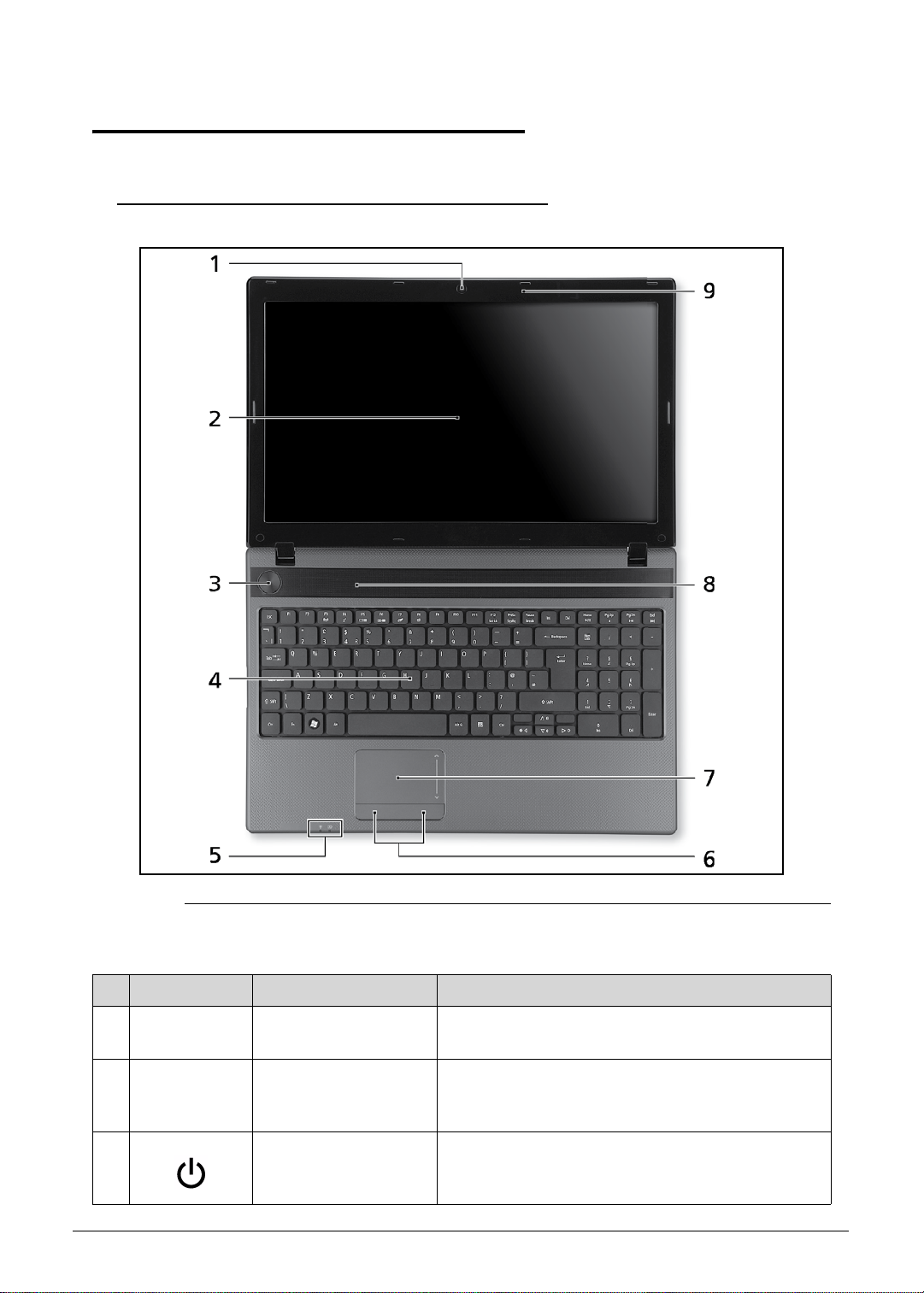
Figure 1-1. Top View
Table 1-1. Top View
No Icon Item Description
1 Integrated webcam Web camera for video communication (only for
certain models).
2 Display screen Also called Liquid-Crystal Display (LCD), displays
computer output (Configuration may vary by
models).
3 Power button /
indicator
1-10 Hardware Specifications and Configurations
Turns the computer on and off. Indicates the
computer's power status.
Page 21
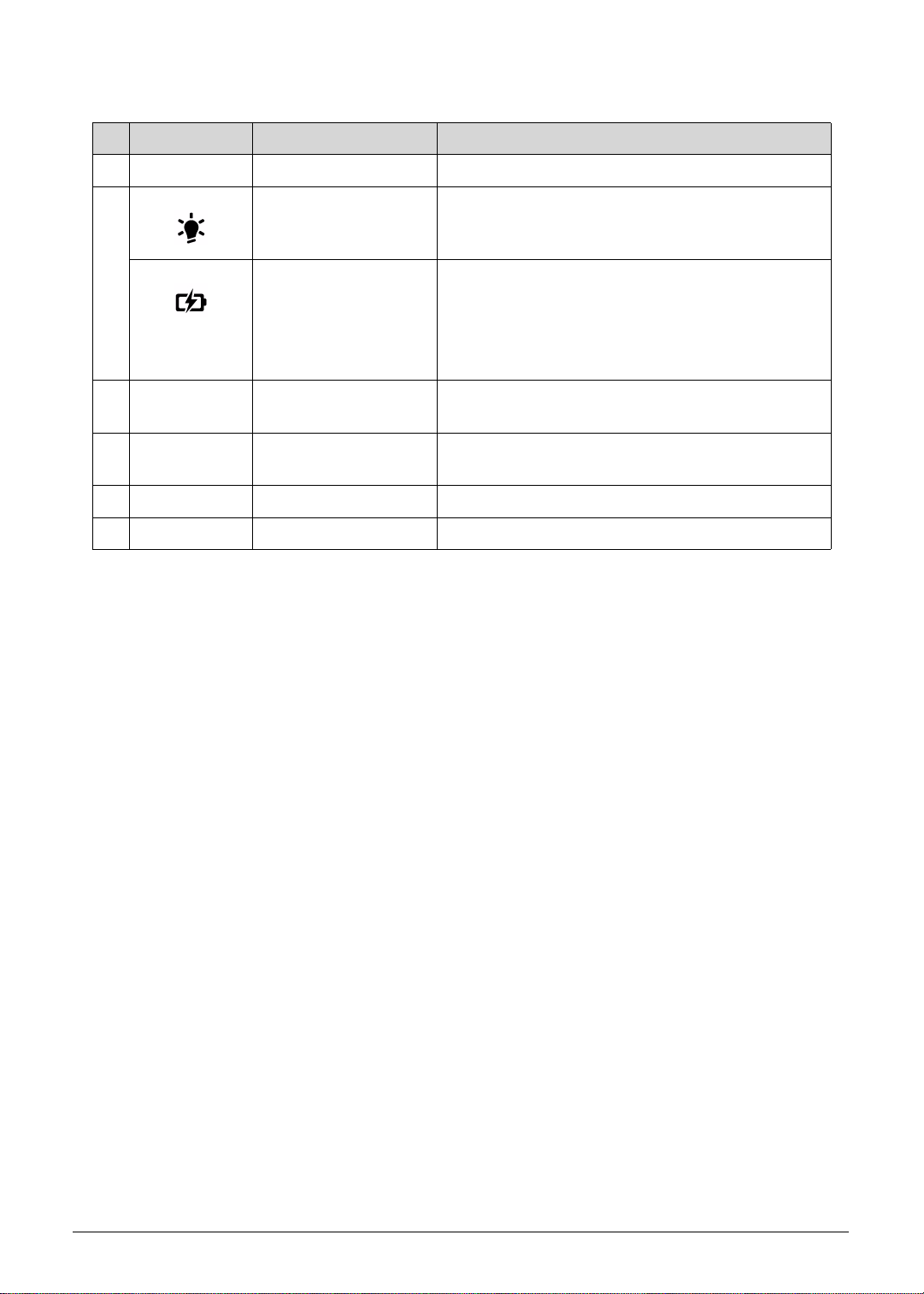
Table 1-1. Top View
No Icon Item Description
4 Keyboard For entering data into your computer.
5 Power indicator Indicates the computer's power status.
Battery indicator Indicates the computer's battery status.
Charging: The light shows amber when the
battery is charging.
Fully charged: The light shows blue when in AC
mode.
6 Click buttons (left and
right)
The left and right buttons function like the lef t and
right mouse buttons.
7 Touchpad Touch-sensitive pointing device which functions
like a computer mouse.
8 Speakers Deliver stereo audio output.
9 Microphone Internal microphone for sound recording.
Hardware Specifications and Configurations 1-11
Page 22
Closed Front View 0
NOTE:
Figure 1-2. Closed Front View
Table 1-2. Closed Front View
No Icon Item Description
1 2-in-1 card reader Accepts Secure Digital (SD), MultiMediaCard
(MMC).
Push to remove/install the card. Only one card
can operate at any given time.
1-12 Hardware Specifications and Configurations
Page 23
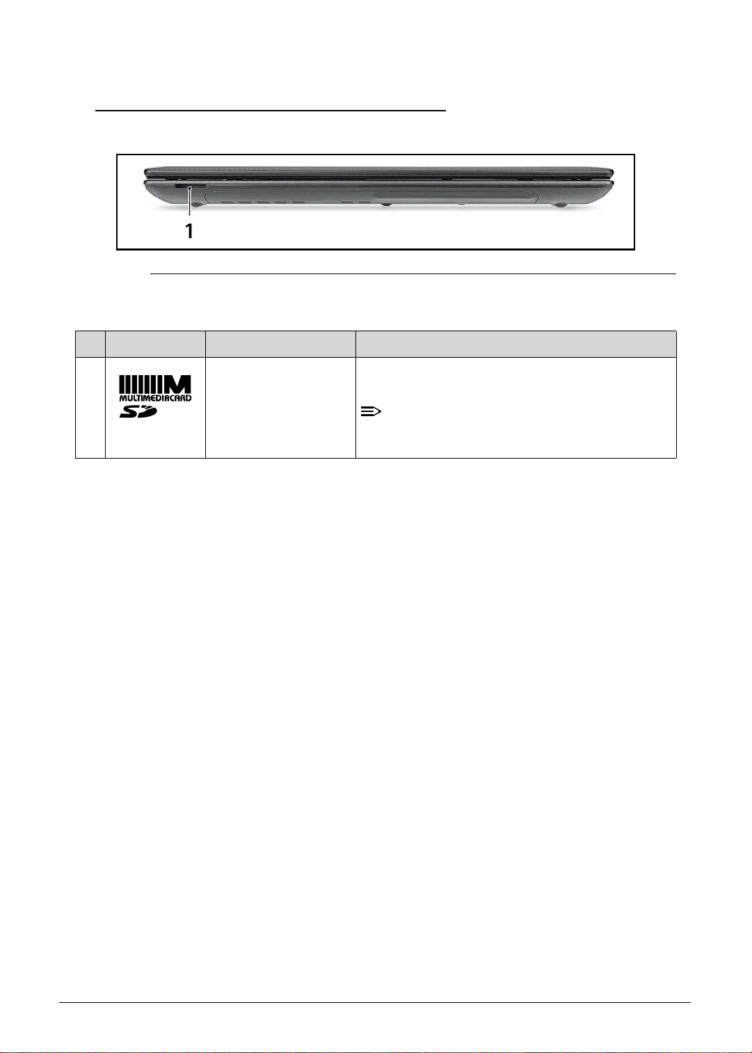
Left View 0
NOTE:
Figure 1-3. Left View
Table 1-3. Left View
No Icon Item Description
1 DC-in jack Connects to an AC adapter.
2 External display
(VGA) port
3 Ethernet (RJ-45) port Connects to an Ethernet 10/100/1000-based
4 USB 2.0 port Connects to USB 2.0 devices (e.g., USB mouse,
5 Microphone jack Accepts inputs from external microphones.
Headphones/speaker
jack
Connects to a display device (e.g., external
monitor, LCD projector).
network.
USB camera).
Connects to audio devices (e.g., speakers,
headphones).
Supports compatible 3.5 mm headsets with
built-in microphone (e.g. Acer smart handheld
headsets).
Hardware Specifications and Configurations 1-13
Page 24
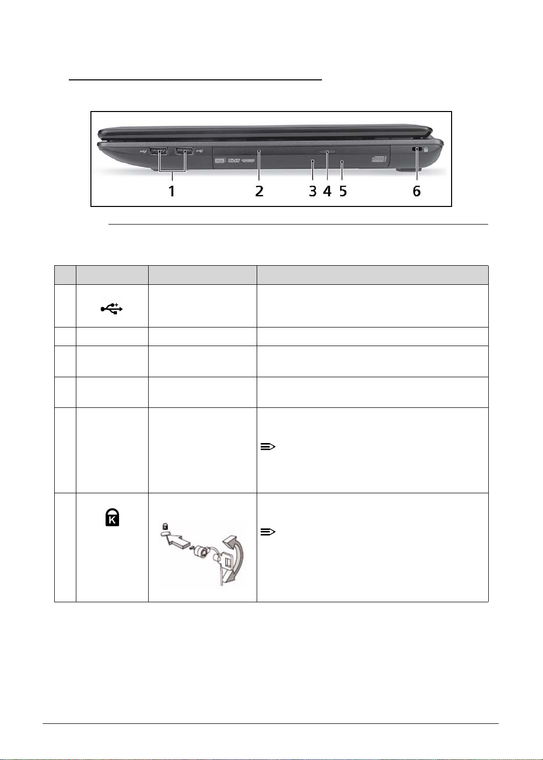
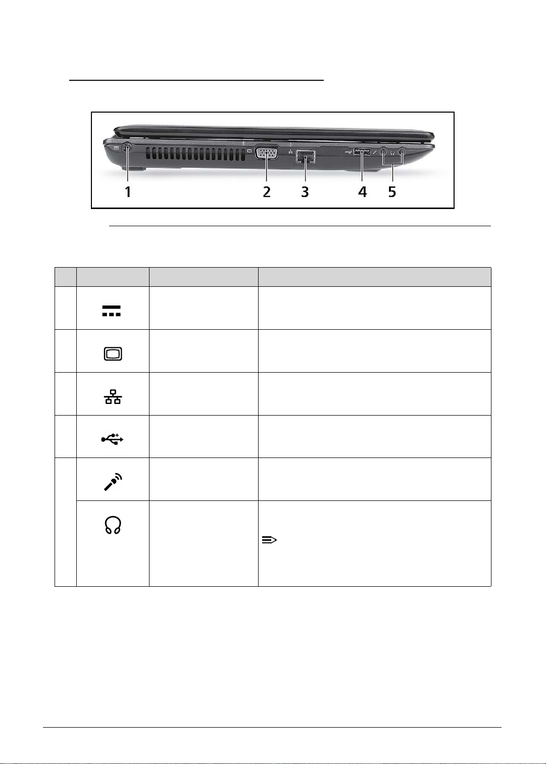
Right View 0
NOTE:
NOTE:
Figure 1-4. Right View
Table 1-4. Right View
No Icon Item Description
1 USB 2.0 ports Connect to USB 2.0 devices (e.g., USB mouse,
USB camera).
2 Optical drive Internal optical drive; accepts CDs or DVDs.
3 Optical drive access
indicator
4 Optical drive eject
button
5 Emergency eject hole Ejects the optical drive tray when the computer is
6 Kensington lock slot Connects to a Kensington-compatible computer
Lights up when the optical drive is active.
Ejects the optical disc from the drive.
turned off.
Insert a paper clip to the emergency eject hole
to eject the optical drive tray when the
computer is off.
security lock.
Wrap the computer security lock cable ar ound
an immovable object such as a table or handle
of a locked drawer. Insert the lock into the
notch and turn the key to secure the lock.
Some keyless models are also available.
1-14 Hardware Specifications and Configurations
Page 25
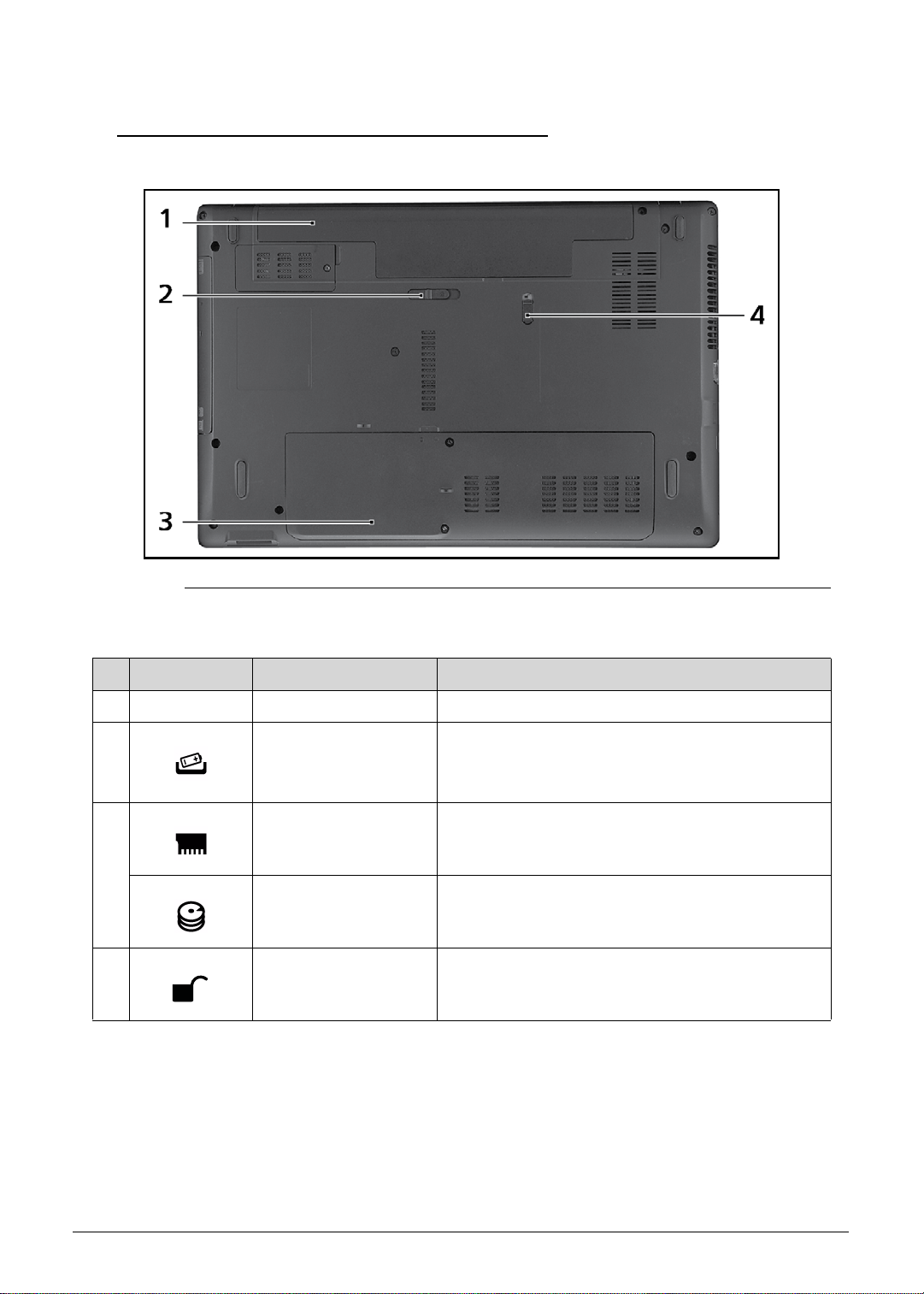
Base View 0
Figure 1-5. Base View
Table 1-5. Base View
No Icon Item Description
1 Battery bay Houses the computer's battery pack.
2 Battery release latch/
lock
3 Memory compartment Houses the computer's main memory.
Hard disk bay Houses the computer's hard disk (secured with
4 Battery lock Locks the battery in position.
Releases the battery for removal.
Insert a suitable tool into the latch and
slide to release.
screws).
Hardware Specifications and Configurations 1-15
Page 26
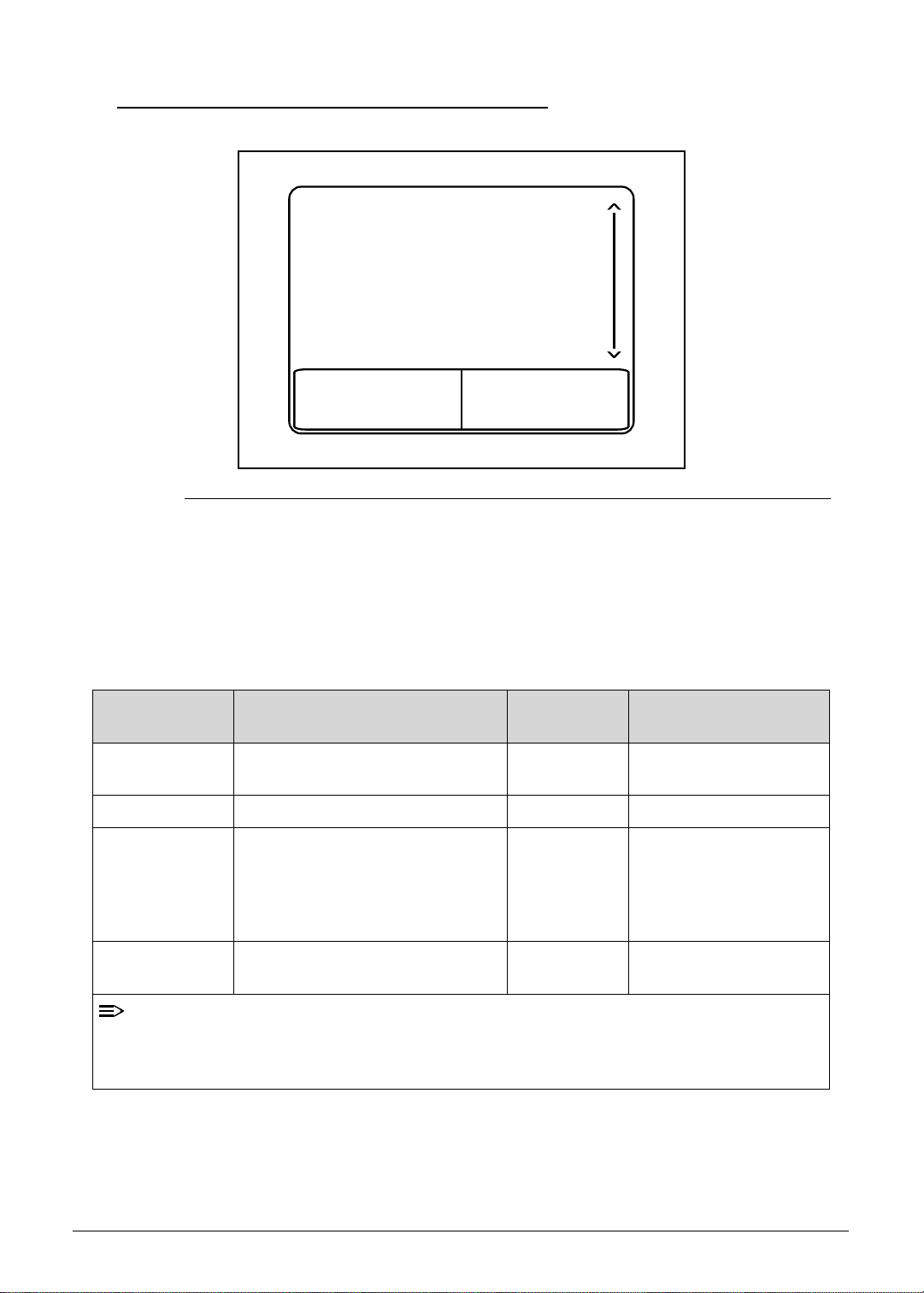
Touchpad Basics 0
NOTE:
1
23
Figure 1-6. Touchpad
Move finger across the Touchpad (1) to move the cursor.
Press the right (2) and left (3) buttons located beneath the Touchpad to perform selection and
execution functions. These two buttons are the equivalent of the left and right buttons on a
mouse. Tapping on the Touchpad is the same as clicking the left button.
Table 1-6. Touchpad
Function Main TouchPad (1) Right Button
(2)
Execute Tap twice (at the same speed as
double-clicking a mouse button).
Select Tap once. Click once.
Drag Tap twice (at the same speed as
double-clicking a mouse button);
rest your finger on the TouchPad
on the second tap and drag the
cursor.
Access context
menu
When using the TouchPad, keep it - and fingers - dry and clean. The TouchPad is sensitive
to finger movement; hence, the lighter the touch, the better the response. Tapping too hard
will not increase the TouchPad’s responsiveness.
Click once.
Left Button (3)
Quickly click twice.
Click and hold, then use
finger on the Touchpad
to drag the cursor.
1-16 Hardware Specifications and Configurations
Page 27

Using the Keyboard 0
Figure 1-7. Keyboard Lock Keys
The keyboard has three lock keys which can be toggled on and off. (Table 1-7)
Table 1-7. Keyboard Lock Keys
Lock key Description
Caps Lock When Caps Lock is on, all alphabetic characters typed are in uppercase.
Num Lock When Num Lock is on, the embedded keypad is in numeric mode. The keys
function as a calculator (complete with the arithmetic operators +, -, *, and /).
Use this mode when doing a lot of numeric data entry. A better solution would
be to connect an external keypad.
Scroll Lock
<Fn> + <F12>
The embedded numeric keypad functions like a desktop numeric keypad. It is indicated by
small characters located on the upper right corner of the key caps. To simplify the keyboard
legend, cursor-control key symbols are not printed on the keys. (Ta b le 1-8)
Table 1-8. Embedded Numeric Keypad
Desired access Num Lock on Num Lock off
Number keys on embedded
keypad
Cursor-control keys on
embedded keypad
When Scroll Lock is on, the screen moves one line up or down when the up or
down arrow keys are pressed respectively. Scroll Lock does not work with
some applications.
Type nu mbers in a normal
manner.
Hold <Shift> while using
cursor-control keys.
Hold <Fn> while using
cursor-control keys.
Main keyboard keys Hold <Fn> while typing letters
on embedded keypad.
Hardware Specifications and Configurations 1-17
Type the letters in a normal
manner.
Page 28
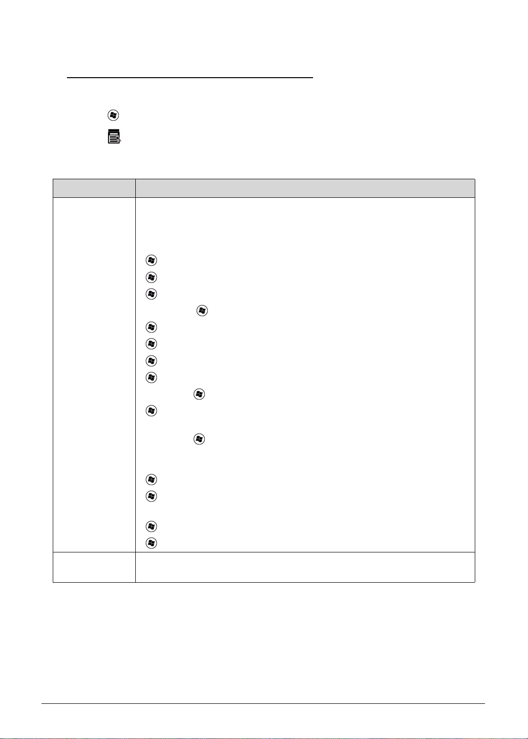
Windows Keys 0
The keyboard has two keys that perform Windows-specific functions.
Windows Logo key
Application key
Table 1-9. Windows Keys
Key Description
Windows Logo
key
Pressed alone, this key has the same ef fect as clicking on the Windows Start
button; it launches the Start menu. It can also be used with other keys to
provide a variety of functions.
Functions supported by Windows XP, Windows Vista, and Windows 7:
< >: Open or close the Start menu
< > + <R>: Open the Run dialog box
< > + <M>: Minimizes all windows
<SHIFT> + < > + M: Undo minimize all windows
< > + <F1>: Show the help window
< > + <E>: Open Windows Explorer
< > + <F>: Search for a file or folder
< > + <D>: Show the desktop
<CTRL> + < > + <F>: Search for computers (if you are on a network)
< > + <L>: Lock your computer (if you are connected to a network
domain), or switch users (if you're not connected to a network domain)
<CTRL> + < > + <TAB>: Moves focus from Start menu, to the Quick
Launch toolbar , to the system tray (use RIGHT ARROW or LEFT ARROW to
move focus to items on the Quick Launch toolbar and the system tray)
< > + <TAB>: Cycle through programs on the taskbar
< > + <BREAK>: Display the System Properties dialog box
Functions supported by Windows XP:
< > + <BREAK>: Show the System Properties dialog box
< > + <U>: Open Ease of Access Center
Application key This key has the same effect as clicking the right mouse button; it opens the
application's context menu.
1-18 Hardware Specifications and Configurations
Page 29
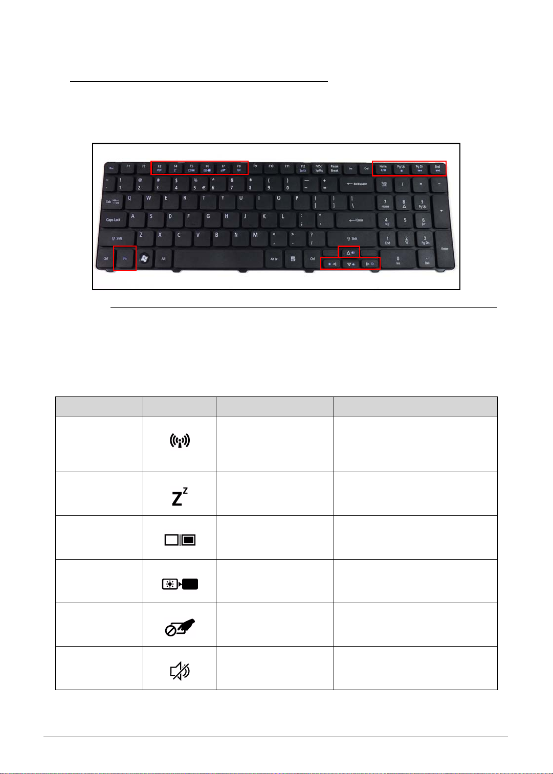
HotKeys 0
Hotkeys or key combinations can be used to access most of the computer's controls like
screen brightness and volume output.
Figure 1-8. Keyboard HotKeys
To activate hotkeys, press and hold the <Fn> key before pressing the other key in the hotkey
combination.
Table 1-10. Keyboard HotKeys
Hotkey Icon Function Description
<Fn> + <F3> Communication switch Enables/disables the computer’s
communication devices.
(Communication devices may
vary by configuration.)
<Fn> + <F4> Sleep Puts the computer in Sleep
mode.
<Fn> + <F5> Display toggle Switches display output between
the display screen, external
monitor (if connected) and both.
<Fn> + <F6> Screen blank Turns the display screen
backlight off to save power. Press
any key to return.
<Fn> + <F7> Touchpad toggle Turns the touchpad on and off.
<Fn> + <F8> Speaker toggle Turns the speakers on and off.
Hardware Specifications and Configurations 1-19
Page 30

Table 1-10. Keyboard HotKeys (Continued)
Hotkey Icon Function Description
<Fn> + <>
<Fn> + <
<Fn> + <
<Fn> + <
<Fn> + <Home> Play/Pause Plays or pauses media files
<Fn> + <Pg Up> Stop Stops media file
<Fn> + <Pg Dn> Previous Plays the previous media file in
>
>
>
Brightness up Increases the screen brightness.
Brightness down Decreases the scree n brig htne ss.
Volume up Increases audio volume.
Volume down Decreases audio volume.
the play sequence
<Fn> + <End> Next Plays the next media file in the
play sequence
1-20 Hardware Specifications and Configurations
Page 31

System Block Diagram 0
USB port 9
Card
Reader
HDA Codec
Mini card
USB port 12
USB port 8
CMOS
Camera
ALC272X
Audio AMP
TPA6017
Int. Speaker
BANK 0, 1, 2, 3
204pin DDRIII-SO-DIMM X2
Dual Channel
6.4G/8.5G/10.6G
100M/133M/166M(CFD)
1.5V DDRIII 800/1066/1333
Memory BUS(DDRIII)
Intel
Processor
Arrandale (UMA)
rPGA988A
USB port 0 (Right Low)
USB Port 1 (Left)
USB conn x3
DMI x4
FDI x8
(UMA)
100MHz
USB port 2 (Right High)
1GB/s x4
100MHz
PCH
100MHz
SPI
port 1
port 0
10/100M LAN
SATA ODD
Conn.
SATA HDD
Conn.
SPI ROM
BCM57780
RJ45 Conn.
LPC BUS
33MHz
ENE KB926
Int.KBD
Touch Pad
BIOS ROM
100MHz
3.3V 48MHz
3.3V 24MHz
HD Audio
USBx14
SATA x 6 (GEN1 1.5GT/S ,GEN2 3GT/S)
Intel
Ibex Peak-M
2.7GT/s
CRT(UMA)
LVDS(UMA)
LVDS Conn.
port 2,4 port 1
MINI Card x1
WLAN
CRT Conn.
Figure 1-9. System Block Diagram
Hardware Specifications and Configurations 1-21
Page 32

Specification Tables 0
NOTE:
Computer specifications
Item Metric Imperial
Dimensions
Length 25.30 cm 9.96 in
Width 38.16 cm 15.02 in
Height
(front to rear)
Weight (equipped with optical
drive, flash drive, and battery)
Input power
Operating voltage 19.0 V dc @ 4.74 A - 90 W
Operating current 4.74 A
Temperature
Operating (not writing to
optical disc)
Operating (writing to optical
disc)
Nonoperating -20°C to 60°C -4°F to 140°F
Relative humidity
Operating 10% to 90%
Nonoperating 5% to 95%
Maximum altitude (unpressurized)
2.74 to 3.40 cm 1.08 to 1.34 in
2.5 kg 5.51 lbs
0°C to 35°C 32°F to 95°F
5°C to 35°C 41°F to 95°F
Operating -15 m to 3,048 m -50 ft to 10,000 ft
Nonoperating -15 m to 12,192 m -50 ft to 40,000 ft
Shock
Operating 125 g, 2 ms, half-sine
Nonoperating 200 g, 2 ms, half-sine
Random vibration
Operating 0.75 g zero-to-peak, 10 Hz to 500 Hz, 0.25 oct/min sweep rate
Nonoperating 1.50 g zero-to-peak, 10 Hz to 500 Hz, 0.25 oct/min sweep rate
Applicable product safety standards specify thermal limits for plastic surfaces. The comp uter
operates well within this range of temperatures.
1-22 Hardware Specifications and Configurations
Page 33

System Board Major Chips
Item Specification
Core logic
VGA
®
HM55
Intel
®
Intel
Arrandale (MCP Processor)
LAN Broadcom BCM57780A1KMLG for 10/100M LAN Controller
USB 2.0
Super I/O controller
Intel
Intel
®
HM55
®
HM55
Bluetooth N/A
Wireless Atheros HB93/HB95/HB97, Broadcom 943225/43225/4313/4312,
RTL8192
PCMCIA N/A
Audio codec Realtek ALC272-X
Card reader Realtek RTS-5137-GR
Processor
Item Specification
CPU type
®
Intel
Core (i3, i5) Processor/Intel® Pentium
CPU package rPGA988A
Core Logic Two execution cores
A 32-KB instruction and 32-KB data first-level cache (L1) for each
core
A 256-KB shared instruction/data second-level cache (L2) for each
core
Up to 4-MB shared instruction/data third-level cache (L3), shared
among all cores
Chipset
Mobile Intel
®
HM55 Express Chipset
Hardware Specifications and Configurations 1-23
Page 34

Processor Specifications
Item CPU Speed
(GHz)
Cores/
Threads
Bus Speed
(FSB/
DMI/QBI)
P6100 2 2 FSB:NA
QPI:NA
DMI: 2.5 GT/s
P6200 2.13 2 FSB:NA
QPI:NA
DMI: 2.5 GT/s
I3-350M 2.26 2/4 FSB:NA
QPI:NA
DMI: 2.5 GT/s
I3-370M 2.4 2/4 FSB:NA
QPI:NA
DMI: 2.5 GT/s
I3-380M 2.53 2/4 FSB:NA
QPI:NA
DMI: 2.5 GT/s
I5-460M 2.53 2/4 FSB:NA
QPI:NA
DMI: 2.5 GT/s
Mfg
Tech
(nm)
Cache
Size
(MB)
Package Voltage
32 3 rPGA988A 0.8-1.4V
32 3 rPGA988A 0.8-1.4V
32 3 rPGA988A 0.8-1.4V
32 3 rPGA988A 0.8-1.4V
32 3 rPGA988A 0.8-1.4V
32 3 rPGA988A 0.8-1.4V
I5-560M 2.66 2/4 FSB:NA
32 3 rPGA988A 0.8-1.4V
QPI:NA
DMI: 2.5 GT/s
CPU Fan True Value Table (Tj=105)
CPU Temperature Fan Speed (RPM) SPL Spec (dBA)
60 2500 28
70 2900 31
80 3200 34
90 3600 37
100 4000 40
Throttling 50%: On= 95 °C; OFF=80 °C
OS shut down at 100 °C; H/W shut down at 90 °C
1-24 Hardware Specifications and Configurations
Page 35

CPU Fan True Value Table (Tj=90)
CPU Temp Fan Speed (RPM) SPL Spec (dBA)
57 2500 28
64 2900 31
70 3200 34
78 3600 37
85 4000 40
Throttling 50%: On= 85 °C; OFF=72 °C
OS shut down at 104 °C; H/W shut down at 92°C
System Memory
Item Specification
Memory controller Built in at CPU
Memory size 512MB, 1GB, 2GB, 4GB DDR3 RAM
DIMM socket number 2
Supports memory size per socket 4 GB
Supports maximum memory size 8 GB
Supports DIMM type Support DDR III 800/1066/1333Mhz
Supports DIMM Speed 800/1066Mhz SDRAM
Support DIMM voltage +1.5V
Supports DIMM package 204pin DDRIII-SO-DIMM
Hardware Specifications and Configurations 1-25
Page 36

Memory Combinations
Slot 1 (MB) Slot 2 (MB) Total Memory (MB)
0 512 512
0 1024 1024
0 2048 2048
0 4096 4096
512 0 512
512 512 1024
512 1024 1536
512 2048 2560
512 4096 4608
1024 0 1024
1024 512 1536
1024 1024 2048
1024 2048 3072
1024 4096 5120
2048 0 2048
2048 512 2560
2048 1024 3072
2048 2048 4096
2048 4096 6144
4096 0 4096
4096 512 4608
4096 1024 5120
4096 2048 6144
4096 4096 8192
Video Inte rface
Item Specification
Chipset
®
Intel
Arrandale (MCP Processor)
Package rPGA package (Rpga 988A)
Interface
®
Intel
Flexible Display Interface (FDI)
Compatibility 8 bpp
Sampling rate Each channel transports at a rate of 2.7Gbps
1-26 Hardware Specifications and Configurations
Page 37

BIOS
Item Specification
BIOS vendor Insyde
BIOS Version 1.00
BIOS ROM type MX25L3205D, MX25L3206E, W25Q32BV, EN25F32
BIOS ROM size 4MB
Features
Insyde code base
Flash ROM 4 MB
Support ISIPP
Support Acer UI
Support multi-boot
Suspend to RAM (S3)/Disk (S4)
Various hot-keys for system control
Support SMBIOS 2.3, PCI2.2.
DMI utility for BIOS serial number configurable/asset tag
Support PXE
Support WinFlash
Wake on LAN from S3
Wake on LAN from S5 in AC mode
System information
HDD password
Refer to Acer BIOS specification.
LAN Interface
Item Specification
LAN Chipset BCM57780
LAN connector type RJ45
LAN connector location JRJ45 at the left side
Features Supports 10/100
Hardware Specifications and Configurations 1-27
Page 38

Keyboard
Item Specification
Type New Acer TM7T flat keyboard
Total number of keypads 105-US/106-UK keys
Windows logo key Yes
Internal & external keyboard
Plug USB keyboard to the USB port directly: Yes
work simultaneously
Features
Phantom key auto detect
Overlay numeric keypad
Support independent pgdn/pgup/home/end keys
Support reverse T cursor keys
Factory configurable different languages by OEM customer
Hard Disk Drive (AVL components)
Item Specification
Vendor & Model
Name
Capacity (GB)
Western Digital
WD3200BEVT22A23T0
HITACHI
HTS545032B9A
300
SEAGATE
ST9320315AS
320 320 320 320
TOSHIBA
MK3265GSX
Bytes per sector 512 512 512 512
Data heads 2332
Drive Format
Disks 1221
Spindle speed
5400
(RPM)
Performance Specifications
Buffer size 8MB
Interface SATA
Fast data transfer
3.03.03.03.0
rate (Gbits/sec,
max)
Media data transfer
106 875 1175 1273.3
rate
(Mbytes/sec max)
DC Power Requirements
Voltage tolerance 5V
1-28 Hardware Specifications and Configurations
Page 39

Super-Multi Drive
Item Specification
Vendor & Model name HLDS Super-Multi Drive DL 8X GT32N LF/SONY Super-Multi
Drive DL 8X AD-7585H LF/Panasonic Super-Multi Drive DL 8X
UJ890/PLDS Super-Multi Drive DL 8X DS-8A4SH/HLDS
Super-Multi Drive DL 8X GT30N LF/HLDS Super-Multi Drive
DL 8X GT31N LF
Performance Specification With CD Diskette With DVD Diskette
Transfer rate (Mbytes/sec) Sustained: Max 3.6 Sustained: Max 10.08
Buffer Memory 2MB
Interface SATA
Applicable disc format Applicable disc format CD: CD-DA, CD-ROM, CD-ROM XA,
Photo CD (multi-session), Video CD, Cd-Extra (CD+), CD-text
DVD: DVD-VIDEO, DVD-ROM, DVD-R (3.9GB, 4.7GB)
DVD-R DL, DVD-RW, DVD-RAM, DVD+R, DVD+RDL,
DVD+RW CD: CD-DA (Red Book) - Standard Audio CD &
CD-TEXT CD-ROM (Yellow Book Mode1 & 2) - Standard Data
CD-ROM XA (Mode2 Form1 & 2) - Photo CD, Multi-Session
CD-I (Green Book, Mode2 Form1 & 2, Ready, Bridge)
CD-Extra/ CD-Plus (Blue Book) - Audio & T ext/V ideo Video-CD
(White Book) - MPEG1 Video CD-R (Orange Book Part)
CD-RW & HSRW (Orange Book Part Volume1 & Volume 2
Super Audio CD (SACD) Hybrid type US & US+ RW DVD:
DVD-ROM (Book 1.02), DVD-Dual DVD-Video (Book 1.1)
DVD-R (Book 1.0, 3.9G) DVD-R (Book 2.0, 4.7G) - General &
Authoring DVD+R (Version 1.0) DVD+RW DVD-RW (Non
CPRM & CPRM) DVD°"R Dual
Loading mechanism Load: Manual Release: (a) Electrical Release (Release Button)
(b) Release by ATAPI command (c) Emergency Release
Power Requirement
Input Voltage 5 V +/- 5% (Operating)
Hardware Specifications and Configurations 1-29
Page 40

BD Drive
Items Specifications
Vendor & Model
name
Performance
Specification
Transfer rate
(Mbytes/sec)
Buffer Memory 2MB 4.5MB
Interface SATA
Applicable disc
format
PLDS BD COMBO DRIVE TRAY DL DS-4E1S LF/HLDS BD COMBO
12.7mm Tray DL CT21N/SONY BD COMBO DRIVE TRAY DL
BC-5500H-AR
With CD Disc With DVD Disc With Blu-ray Disc
Sustained: Max 3.6 Sustained: Max 10.08 Sustained: M ax 11
Applicable disc format CD: CD-DA, CD-ROM, CD-ROM XA, Photo CD
(multi-session), Video CD, Cd-Extra (CD+), CD-text DVD:
DVD-VIDEO, DVD-ROM, DVD-R (3.9GB, 4.7GB) DVD-R DL,
DVD-RW, DVD-RAM, DVD+R, DVD+R DL, DVD+RW CD: CD-DA
(Red Book) - Standard Audio CD & CD-TEXT CD-ROM (Yellow Book
Mode1 & 2) - Standard Data CD-ROM XA (Mode2 Form1 & 2) - Photo
CD, Multi-Session CD-I (Green Book, Mode2 Form1 & 2, Ready,
Bridge) CD-Extra/ CD-Plus (Blue Book) - Audio & T ext/Video Video -CD
(White Book) - MPEG1 Video CD-R (Orange Book Part) CD-RW &
HSRW (Orange Book Part Volume1 & Volume 2 Super Audio CD
(SACD) Hybrid type US & US+ RW DVD: DVD-ROM (Book 1.02),
DVD-Dual DVD-Video (Book 1.1) DVD-R (Book 1.0, 3.9G) DVD-R
(Book 2.0, 4.7G) - General & Authoring DVD+R (V er sion 1.0) DVD+RW
DVD-RW (Non CPRM & CPRM) DVD+/-R Dual Blu-Ray: BD-R, BD-R
DL, BD-RE, BD-RE DL
Loading mechanism Load: Manual Rele as e: (a ) Electrical Release (Release Button) (b)
Release by ATAPI command (c) Emergency Release
Power Requirement
Input Voltage 5 V +/- 5% (Operating)
1-30 Hardware Specifications and Configurations
Page 41

LED 15.6”
Item Specification
Vendor/Model name
AUO/B156XW02 V3
Samsung/LTN156AT02-101
LG/LP156WH2-TLF1
LG/LP156WH2-TLFA
AUO/B156XW02 V2 (HW:4A)
Samsung/LTN156AT02-A02
LG/LP156WH2-TLE1
LG/LP156WH2-TLEA
CMO/N156B6-L0B
INNOLUX/BT156GW01 V2
Screen Diagonal (mm) 394.91 mm
Active Area (mm) 344.23 mm x 193.54 mm
Display resolution (pixels) 1366 x 3(RGB) x 768
Pixel Pitch (mm) 0.252mm × 0.252 mm
Typical White Luminance
2
(cd/m
) also called Brightness
220 cd/m
2
Contrast Ratio 400 min / 500 type
Response Time (Optical Rise
8 ms / 16 ms
Time/Fall Time) msec
Typical Power Consumption
5.15 W
(watt)
Weight (without inverter) 460 max
Physical Size (mm) 360 mm x 210mm x 5.5 max
Electrical Interface 1 channel LVDS
Viewing Angle (degree)
40 (Right) / 40 (Left) / 10 (Upper) / 30 (Lower) min.
Horizontal (Right) CR = 10
(Left)
Vertical (Upper) CR = 10
(Lower)
Hardware Specifications and Configurations 1-31
Page 42

LCD Inverter (not available in this model)
Item Specification
Vendor & Model name
Brightness conditions
Input voltage (v)
Input current (mA)
Output voltage (V, RMS)
Output current (mA, RMS)
Output voltage frequency
(KHz)
Display Supported Resolution (LCD)
Resolution 16 bits 32 bits 36 bits 48 bits other
800x600p/60Hz 16:9 V V V V V
1024x768p/60Hz 16:9 V V V V V
1280x600/60Hz 16:9 V V V X X
1280x720/60Hz 16:9 V V V V V
1280x768/60Hz 16:9 V V V V V
1360x768/60Hz 16:9 V V V V V
1366x768/60Hz 16:9 V V V V V
Graphics Controller
Item Specification
VGA Chip Intel Arrandale (MCP Processor)
Supports
Intel
Intel
®
Hyper-Threading technology
®
64 architecture
Display Supported Resolution (GPU)
Resolution 16 bits 32 bits 36 bits 48 bits other
800x600p/60Hz 16:9 V V X X X
1024x768p/60Hz 16:9 V V X X X
1280x600/60Hz 16:9 V V X X X
1280x720/60Hz 16:9 V V X X X
1280x768/60Hz 16:9 V V X X X
1360x768/60Hz 16:9 V V X X X
1366x768/60Hz 16:9 V V X X X
1-32 Hardware Specifications and Configurations
Page 43

Bluetooth Interface (not available in this model)
Item Specifications
Chipset
Data throughput
Protocol
Interface
Connector type
Supported protocol
Bluetooth Module (not available in this model)
Item Specifications
Controller
Features
Camera
Item Specification
Vendor and Model Lite-on 10P2SF005, Suyin HF0319-M08C-OV01, Suyin
CN1014-S36D-OV05
Type 0.3M
Mini Card
Item Specification
Number supported 1
Features 1 mini card slot (for WLAN or WLAN/WiMax)
3G Card (not available in this model)
Item Specification
Features
Hardware Specifications and Configurations 1-33
Page 44

Audio Codec and Amplifier
Item Specification
Audio Controller Audio codec: Realtek ALC272X-GR
Features
Two stereo DAC support 16/20/24-bit PCM for two
independent playback (multiple streaming)
Two stereo ADC supports 16/20/24-bit PCM format for two
independent recording
All DACs support independent 44.1k/48k/96k/192kHz sample
rate
All ADCs support independent 44.1k/48k/96k/192kHz sample
rate
Two independent SPDIF outputs support 16/20/24-bit format
and 44.1k/48k/88.2k/96k/192kHz rate
Supports line level mono output
Supports analog PCBEEP input, and features an integrated
digital BEEP generator
Support two stereo digital microphone input for microphone
array AEC/BF application
Supports legacy analog mixer architecture
Supports two GPIO (General Purpose Input/Output) pins (pin
sharing with digital microphone interface)
Supports EAPD (External Amplifier Power Down) control for
external amplifier
Supports anti-pop mode when analog power AVDD is on and
digital power is off
Supports 1.5V~3.3V scalable I/O for HD Audio link
48-pin LQFP 'Green' package
Amplifier TI TPA6017A2PWPR,
Features
4 step gain control
2-W/Ch Output Power Into 3-? Load From 5-V Supply
Fully Differential Input
Low Supply Current and Shutdown selection
Embedded de-pop circuit
Audio Interface
Item Specification
Audio Controller Realtek ALC272X-GR
Audio onboard or optional On board
Mono or Stereo Stereo
Resolution Support 16/24bit PCM
Compatibility HD audio Interface;
Sampling rate Sample rate up to 192Khz resolution VSR (Variable Sampling
Rate)
1-34 Hardware Specifications and Configurations
Page 45

Item Specification
Audio Interface (continue d )
Internal microphone Yes
Internal speaker/quantity Yes/(1W speakers x2)
Wireless Module 802.11b/g/n
Item Specification
Chipset Atheros HB93/HB95/HB97, BCM943225/ BCM4312, Intel
6200/1000
Data throughput 11~54 Mbps, up to 270 Mbps for Draft-N
Protocol 802.11 b+g, Drat-N
Interface PCI bus (mini PCI socket for wireless module)
Battery
Item Specification
Vendor & Model na me SANYO AS10D31 SIMPLO AS10D71/75
Battery Type Li-ion Li-ion
Pack capacity 2200 mAh 2200 mAh
Number of battery cell 6 6
Package configuration 3S2P 3S2P
Item Specification
Vendor & Model name SONY AS10D41 SAMSUNG AS10D61
Battery Type Li-ion Li-ion
Pack capacity 2200 mAh 2200 mAh
Number of battery cell 6 6
Package configuration 3S2P 3S2P
Item Specification
Vendor & Model name PANASONIC AS10D51 PANASONIC AS10D56
Battery Type Li-ion Li-ion
Pack capacity 2200 mAh 2900 mAh
Number of battery cell 6 4
Package configuration 3S2P 4S1P
Hardware Specifications and Configurations 1-35
Page 46

VRAM (not available in this model)
NOTE:
Item Specification
Chipset N/A
Memory size N/A
Interface N/A
USB Port
Item Specification
USB compliance level USB 2.0
EHCI EHCI
Number of USB port(s) 3
Location one at the left side, and two at the right side
Output Current
1.5A
2.0A
2.5A
HDMI Port (not available in this model)
Item Specification
Compliance level
Data thoroughput
Number of HDMI port(s)
Location
AC Adapter
Item Specification
Input rating 65W*
Maximum input AC current 1.7A at 100V
Inrush current 12t at 264V no damage
Efficiency Refer to EP A 2.0
*The information is from the Approved Vendor List (AVL).
1-36 Hardware Specifications and Configurations
Page 47

System Power Management
Item Specification
Mech. Off (G3) All devices in the system are turned off completely.
Soft Off (G2/S5) OS initiated shutdown. All devices in the system are turned off
completely.
Working (G0/S0) Individual devices such as the CPU and har d disc may be
power managed in this state.
Suspend to RAM (S3)
CPU set power down
VGA Suspend
PCMCIA Suspend
Audio Power Down
Hard Disk Power Down
CD-ROM Power Down
Super I/O Low Power mode
Save to Disk (S4) Also called Hibernation Mode. System saves all system states
and data onto the disc prior to power off the whole system.
Card Reader
Item Specification
Chipset Realtek RTS5137-GR
Package LQFP 24P
Maximum supported size
SD: 16G
MMC: 16G
miniSD: 16G
Features 2 in 1 card reader, supporting:
Secure Digital™ (SD) Card, MultiMediaCard™ (MMC)
Storage cards with adapter: miniSD™
Hardware Specifications and Configurations 1-37
Page 48

System LED Indicator
Item Specification
Lock N/A
System state Blue color solid on: System on
Blue color off: System off
HDD access state N/A
Wireless stat e N/A
Power button backlight N/A
Battery state Charging
Amber solid on - Battery charging with AC
Blue color solid on - Battery full
Amber blinking - Battery abnormal stop charge or batter in
low power state
Discharging
Amber and blinking - Battery in critical low state
Amber color off - Discharging state
System DMA Specification
Legacy Mode Power Management
DMA0 Not applicable
DMA1 Not applicable
DMA2 Not applicable
DMA3 Not applicable
DMA4 Direct memory access controller
DMA5 Available for ExpressCard
DMA6 Not Assigned
DMA7 Not Assigned
*ExpressCard controller can use DMA 1, 2, or 5.
1-38 Hardware Specifications and Configurations
Page 49

System Interrupt Specification
NOTE:
Hardware IRQ System Function
IRQ0 System timer
IRQ1
Standard 101-/102-Key or Microsoft
IRQ2 Cascaded
IRQ3
®
Intel
82801DB/DBM USB2 Enhanced Host Controller-24CD
IRQ4 COM1
IRQ5*
Conexant AC-Link Audio Intel 82801DB/DBM SMBus
Controller-24C3 Data Fax
Modem with SmartCP
IRQ6 Diskette drive
IRQ7* Parallel port
IRQ8 System CMOS/real-time clock
IRQ9* Microsoft ACPI-compliant system
IRQ10*
IRQ11
®
Intel
Intel
Realtek RTL8139 Family PCI Fast Ethernet Controller
Intel
Intel
Intel
Intel
TI OHCI 1394 host controller
TI PCI1410 CardBus controller
USB UHCI controller-24C2
®
82852/82855 GM/GME Graphic Controller
®
USB EHCI controller-24CD
®
USB UHCI controller-24C4
®
USB UHCI controller-24C7
®
Pro/Wireless 2200BG
®
Natural Keyboard
IRQ12 Synaptics PS/2 TouchPad
IRQ13 Numeric data processor
IRQ14 Primary IDE channel
IRQ15 Secondary IDE channel
* Default configuration; audio possible configurations are IRQ5, IRQ7, IRQ9, IRQ10, or none.
ExpressCards may assert IRQ3, IRQ4, IRQ5, IRQ7, IRQ9, IRQ10, IRQ11, or IRQ15. Either
the infrared or the serial port may assert IRQ3 or IRQ4.
Hardware Specifications and Configurations 1-39
Page 50

System IO Address Map
I/O address (hex) System function (shipping co nfiguration)
000 - 00F DMA controller no. 1
010 - 01F Unused
020 - 021 Interrupt controller no. 1
022 - 024 Opti chipset configuration registers
025 - 03F Unused
02E - 02F 87334 "Super I/O" configuration for CPU
040 - 05F Counter/timer registers
044 - 05F Unused
060 Keyboard controller
061 Port B
062 - 063 Unused
064 Keyboard controller
065 - 06F Unused
070 - 071 NMI enable/RTC
072 - 07F Unused
080 - 08F DMA page registers
090 - 091 Unused
092 Port A
093 - 09F Unused
0A0 - 0A1 Interrupt controller no. 2
0A2 - 0BF Unused
0C0 - 0DF DMA controller no. 2
0E0 - 0EF Unused
0F0 - 0F1 Coprocessor busy clear/reset
0F2 - 0FF Unused
100 - 16F Unused
170 - 177 Secondary fixed disk controller
178 - 1EF Unused
1F0 - 1F7 Primary fixed disk controller
1F8 - 200 Unused
201 JoyStick (decoded in ESS1688)
202 - 21F Unused
1-40 Hardware Specifications and Configurations
Page 51

System I/O Address Specifications
I/O address (hex) System Function (shipping configuration)
220 - 22F Entertainment audio
230 - 26D Unused
26E - 26 Unused
278 - 27F Unused
280 - 2AB Unused
2A0 - 2A7 Unused
2A8 - 2E7 Unused
2E8 - 2EF Reserved serial po rt
2F0 - 2F7 U nu se d
2F8 - 2FF Infrared port
300 - 31F Unused
320 - 36F Unused
370 - 377 Secondary diskette drive controller
378 - 37F Parallel port (LPT1/default)
380 - 387 Unused
388 - 38B FM synthesizer-OPL3
38C - 3AF Unused
3B0 - 3BB VGA
3BC - 3BF Reserved (parallel port/no EPP support)
3C0 - 3DF VGA
3E0 - 3E1 ExpressCard controller in CPU
3E2 - 3E3 Unused
3E8 - 3EF Internal modem
3F0 - 3F7 "A" diskette controller
3F8 - 3FF Serial port (COM1/default)
CF8 - CFB PCI configuration index register (PCIDIVO-1)
CFC - CFF PCI configuration data register (PCIDIVO-1)
Hardware Specifications and Configurations 1-41
Page 52

1-42 Hardware Specifications and Configurations
Page 53

CHAPTER 2
System Utilities
Page 54

BIOS Setup Utility. . . . . . . . . . . . . . . . . . . . . . . . . . . . . . . . . . . . . 2-3
Navigating the BIOS Utility . . . . . . . . . . . . . . . . . . . . . . . . . . 2-3
BIOS . . . . . . . . . . . . . . . . . . . . . . . . . . . . . . . . . . . . . . . . . . . . . . . 2-4
Information. . . . . . . . . . . . . . . . . . . . . . . . . . . . . . . . . . . . . . . 2-4
Main . . . . . . . . . . . . . . . . . . . . . . . . . . . . . . . . . . . . . . . . . . . . 2-6
Security . . . . . . . . . . . . . . . . . . . . . . . . . . . . . . . . . . . . . . . . . . 2-8
Boot. . . . . . . . . . . . . . . . . . . . . . . . . . . . . . . . . . . . . . . . . . . . . 2-13
Exit. . . . . . . . . . . . . . . . . . . . . . . . . . . . . . . . . . . . . . . . . . . . . . 2-14
BIOS Flash Utilities . . . . . . . . . . . . . . . . . . . . . . . . . . . . . . . . . . . . 2-15
Remove HDD/BIOS Password Utilities . . . . . . . . . . . . . . . . . . . . . 2-16
Clearing HDD Passwords . . . . . . . . . . . . . . . . . . . . . . . . . . . . 2-16
Removing BIOS Passwords . . . . . . . . . . . . . . . . . . . . . . . . . . . 2-18
Miscellaneous Tools . . . . . . . . . . . . . . . . . . . . . . . . . . . . . . . . . . . 2-19
Using Boot Sequence Selector. . . . . . . . . . . . . . . . . . . . . . . . 2-19
Using Boot Manager . . . . . . . . . . . . . . . . . . . . . . . . . . . . . . . 2-20
Using DMITools. . . . . . . . . . . . . . . . . . . . . . . . . . . . . . . . . . . . 2-20
Using LAN EEPROM Utility. . . . . . . . . . . . . . . . . . . . . . . . . . . 2-22
2-2
Page 55

System Utilities
NOTE:
NOTE:
NOTE:
NOTE:
BIOS Setup Utility 0
This utility is a hardware configuration program built into a computer’s BIOS (Basic
Input/Output System).
The utility is pre-configured and optimized so most users do not need to run it. If configuration
problems occur, the setup utility may need to be run. Refer to Troubleshooting when a problem
arises.
To activate the utility, press
of screen.
The default parameter of F12 Boot Menu is set to Disabled. To change the boot device
without entering BIOS Setup Utility, set the parameter to Enabled.
To change the boot device without entering the BIOS SETUP , press F12 during POST to enter
the multi-boot menu.
Navigating the BIOS Utility 0
Six menu options are:
Information
F2 during POST (power-on self-test) wh en prompted at the bottom
Main
Security
Boot
Exit
To navigate through the following:
Menu - use the left and right arrow keys
Item - use the up and down arrow keys
Change parameter value - press F5 or F6.
Exit - Press Esc
Load default settings - press F9. Press F10 to save changes and exit BIOS Setup
Utility
Parameter values can be changed if enclosed in square brackets [ ]. Navigation keys
appear at the bottom of the screen. Read parameter help carefully when making
changes to parameter values. Parameter help is found in the Item Specific Help area of
the screen.
System information is subject to specific mode ls.
System Utilities 2-3
Page 56

BIOS 0
NOTE:
NOTE:
InsydeH20 Setup Utility Rev. 3.5
F1
ESC
Help
Exit
Select Item
Select Menu
Change Values
Select SubMenu
Enter
F9
F10
Setup Default
Save and Exit
Intel(R) Pentium(R) CPU P6200 @ 2.13GHz
2.13GHz
TOSHIBA MK2559GSXP
11HWB015B
MATSHITADVD-RAM UJ8A0AS
V1.00
Intel V1994
xxxxxxxxxxxxxxxxxxxx (Max: 22 Byte)
xxxxxxxxxxxxxxxxxxxx (Max: 32 Byte)
xxxxxxxxxxxxxxxx (Max: 20 Byte)
eMachines
xxxxxxxxxxxxxxxxxxxx (Max: 16 Byte)
Intel(R) Pentium(R) CPU P6200 @ 2.13GHz
2.13GHz
TOSHIBA MK2559GSXP
11HWB015B
MATSHITADVD-RAM UJ8A0AS
V1.00
Intel V1994
xxxxxxxxxxxxxxxxxxxx (Max: 22 Byte)
xxxxxxxxxxxxxxxxxxxx (Max: 32 Byte)
xxxxxxxxxxxxxxxx (Max: 20 Byte)
eMachines
xxxxxxxxxxxxxxxxxxxx (Max: 16 Byte)
CPU Type:
CPU Speed:
HDD Model Name:
HDD Serial Number:
ATAPI Model Name:
System BIOS Version:
VGA BIOS Version:
Serial Number:
Asset Tag Number:
Product Name:
Manufacturer Name:
UUID:
CPU Type:
CPU Speed:
HDD Model Name:
HDD Serial Number:
ATAPI Model Name:
System BIOS Version:
VGA BIOS Version:
Serial Number:
Asset Tag Number:
Product Name:
Manufacturer Name:
UUID:
F5/F6
Main Boot
Exit
SecurityInformation
The following is a description of the tabs found on the InsydeH20 BIOS Setup Utility screen:
Screens provided are for reference only. Actual values may differ by model.
Information 0
The Information tab shows a summary of computer hardware information.
Figure 2-1. BIOS Information
Table 2-1 describes the parameters shown in Figure 2-1.
Table 2-1. BIOS Information
Parameter Description
CPU Type CPU (central processing unit) type and speed of system
CPU Speed Speed of the CPU
HDD Model Name Model name of HDD0 (hard disk drive) installed on primary IDE
HDD Serial Number Serial number of HDD0 installed on primary IDE master
master
ATAPI Model Name Model name of Optical device installed in system
2-4 System Utilities
Page 57

Table 2-1. BIOS Information (Continued)
Parameter Description
System BIOS Version System BIOS version
VGA BIOS Version VGA (video graphics array) firmware version of system
Serial Number Seri al number of unit
Asset Tag Number Asset tag number of system
Product Name Product name of the system
UUID Universally Unique Identifier
System Utilities 2-5
Page 58

Main 0
The Main tab allows the user to set system time and date, enable or di sable boot option and
enable or disable recovery.
Information
System Time:
System Time:
System Date:
System Date:
Total Memory:
Total Memory:
Video Memory:
Video Memory:
Quiet Boot
Quiet Boot
Network Boot
Network Boot
F12 Boot Menu
F12 Boot Menu
D2D Recovery
D2D Recovery
SATA Mode
SATA Mode
F1
ESC
Main
Help
Exit
Security
Select Item
Select Menu
InsydeH20 Setup Utility Rev. 3.5
Boot
Exit
[00:52:01]
[00:52:01]
[05/27/2010]
[05/27/2010]
[xxxx MB]
[xxxx MB]
[x MB]
[x MB]
[Enabled]
[Enabled]
[Enabled]
[Enabled]
[Disabled]
[Disabled]
[Enabled]
[Enabled]
[AHCI Mode]
[AHCI Mode]
Change Values
F5/F6
Select SubMenu
Enter
Figure 2-2. BIOS Main
Table 2-2 describes the parameters shown in Figure 2-2.
.
Table 2-2. BIOS Main
Item Specific Help
This is the help for the
hour field. Valid range
is from 0 to 23.
/INCREASE
F9
F10
REDUCE
: F5/F6
Setup Default
Save and Exit
Parameter Description Format/Option
System Time BIOS system time in 24-hour format Format: HH:MM:SS
(hour:minute:second)
System Date BIOS system date Format MM/DD/YYYY
(month/day/year)
Total
Total memory available N/A
Memory
Video
Available memory for video N/A
Memory
Quiet Boot Shows OEM (original equipment manufacturer)
screen during system boot instead of traditional
Option: Enabled or
Disabled
POST screen
Network
Boot
F12 Boot
Menu
Option to boot system from LAN (local area network) Option: Enabled or
Disabled
Option to use boot menu during POST Option: Enabled or
Disabled
2-6 System Utilities
Page 59

Table 2-2. BIOS Main (Continued)
Parameter Description Format/Option
D2D
Recovery
Option to use D2D Recovery function Option: Enabled or
Disabled
SA TA Mode Option to set SATA controller mode Option: AHCI or IDE
System Utilities 2-7
Page 60

Security 0
CAUTION:
!
The Security tab shows parameters that safeguard and protect the computer from
unauthorized use.
Information
Supervisor Password Is:
Supervisor Password Is:
User Password Is:
User Password Is:
HDD Password Is:
HDD Password Is:
Set Supervisor Password
Set Supervisor Password
Set User Password
Set User Password
Set HDD Password
Set HDD Password
Password on Boot
Password on Boot
F1
ESC
Main Boot
Help
Exit
Select Item
Select Menu
Security
InsydeH20 Setup Utility Rev. 3.5
Exit
Clear
Clear
Clear
Clear
Clear
Clear
[Disabled]
[Disabled]
Change Values
F5/F6
Select SubMenu
Enter
Figure 2-3. BIOS Security
Table 2-3 describes the parameters shown in Figure 2-3.
Item Specific Help
Install or Change the
password and the length
of password must be less
than one words.
Setup Default
F9
Save and Exit
F10
Table 2-3. BIOS Security
Parameter Description Option
Supervisor Password Is
User Password Is
Set Supervisor Password
Set User Password
Supervisor password setting
User password setting
Option to set supervisor password.
Option to set user password.
Set HDD Password Enter HDD Password. N/A
Password on Boot
If Power-on Password authentication is
Clear or Set
Clear or Set
N/A
N/A
Disabled or
Enabled
enabled, the BIOS password can only be
cleared by initiating the Crisis Disk Recovery
procedure. Refer to BIOS Recovery by Crisis
Disk.
Shows if password is required during system boot
2-8 System Utilities
Page 61

NOTE:
NOTE:
When prompted to enter password, three attempts are allowed before system halts.
NOTE:
NOTE:
NOTE:
NOTE:
IMPORTANT:
+
Resetting BIOS password may require computer be returned to dealer.
Setting a Password 0
Perform the following to set a new user or supervisor passwords:
1. Use the and keys to highlight the Set Supervisor Password parameter and press
Enter. The Set Supervisor Password dialog box appears (Figure 2-4).
To change an existing password, refer to Changing a Password.
Figure 2-4. Setting a Password: Set Supervisor Password
2. Type a new password in the Enter New Password field and press Enter.
The following characters may be used in a password (Table 2-4):
Table 2-4. Allowed Characters
A-Z Alphabets A through Z (Not Case Sensitive)
0-9 Numerical Characters.
-Dash
= Equal Sign
[ Left Bracket
] Right Bracket
.Period
, Comma
; Semi-colon
/Slash
\ Back-slash
Use care when typing a password. Characters do not appear on the screen.
3. Retype password in the Confirm New Password field and press Enter.
4. If new password and confirm new password strings match, the Setup Notice dialog
screen is shown (Figure 2-5). If it is not, go to step 5.
System Utilities 2-9
Page 62

Figure 2-5. Setting a Password Confirmation Notice
Setup Notice
Changes have been saved.
[Continue]Continue
a. Press Enter to return to the BIOS Setup Utility Security menu.
b. The Supervisor Password parameter is shown as Set.
c. Press F10 to save changes and ex it BIOS Setup Utility.
5. If new password and confirm new password strings do not match, the Setup Warning
dialog is shown. (Figure 2-6)
Setup Warning
Passwords do not match.
Re-enter password.
[Continue]Continue
Figure 2-6. Setting a Password: Passwords Do Not Match
a. Press Enter to return to the BIOS Setup Utility Security menu.
b. The Supervisor Password parameter is shown as Clear.
c. To try to set a new password again, repeat steps 1 through 3.
Removing a Password 0
Perform the following:
1. Use the and keys to highlight Set Supervisor Password and press Enter. The
Set Supervisor Password dialog box appears (Figure 2-7):
Figure 2-7. Removing a Password: Set Supervisor Password
2. Type current password in Enter Current Password field and press Enter.
2-10 System Utilities
Page 63

3. Press Enter twice without typing anything in Enter New Password and Confirm New
Password fields. Computer will set Supervisor Password parameter to Clear.
4. Press F10 to save changes and exit the BIOS Setup Utility.
Changing a Password 0
1. Use the and keys to highlight Set Supervisor Password and press Enter. The
Set Supervisor Password dialog box appears (Figure 2-8).
Figure 2-8. Set Supervisor Password
2. Type current password in Enter Current Password field and press Enter.
3. Type new password in Enter New Password field and press Enter.
4. Retype new password in Confirm New Password field and press Enter.
5. If new password and co nfirm new password strings match, The Setup Notice dialog is
shown (Figure 2-9). If it is not shown, go to step 6.
Figure 2-9. Setup Notice
a. Press Enter to return to the BIOS Setup Utility Security menu.
b. The Supervisor Password parameter is shown as Set.
c. Press F10 to save changes and ex it BIOS Setup Utility.
6. If current password and new password string s do not match, the Setup Warning dialog
is shown (Figure 2-10). If it is not shown, go to step 7.
Setup Warning
Passwords do not match.
Re-enter password.
[Continue]Continue
Figure 2-10. Changing a Password: Invalid Password
System Utilities 2-11
Page 64

a. Press Enter to return to the BIOS Setup Utility Security menu.
b. The Supervisor Password parameter is shown as Clear.
c. To try to change the password again, repeat steps 1 through 4.
If new password and confirm new password strings do not match, the Setup Warning dialog
is shown (Figure 2-11).
Figure 2-11. Changing a Password: Passwords Do Not Match
a. Press Enter to return to the BIOS Setup Utility Security menu.
b. The Supervisor Password parameter is shown as Clear.
c. To try to change the password again, repeat steps 1 through 4.
2-12 System Utilities
Page 65

Boot 0
Item Specific Help
Use < > or < > to select
a device, then press
<F5> to move it down the
list, or <F6> to move
it up the list. Press
<Esc> to escape the menu
F1
ESC
Help
Exit
Select Item
Select Menu
Change Values
Select SubMenu
Enter
F9
F10
Setup Default
Save and Exit
Boot priority order:
1. IDE 0: ST960821A
2. IDE 1: MATSHITADVD
3: USB FDD:
4. Network Boot: Realtek Boot Agent
5. USB HDD:
6. USB CDROM:
Boot priority order:
1. IDE 0: ST960821A
2. IDE 1: MATSHITADVD
3: USB FDD:
4. Network Boot: Realtek Boot Agent
5. USB HDD:
6. USB CDROM:
F5/F6
InsydeH20 Setup Utility Rev. 3.5
Information
Main Boot
Exit
Security
This tab allows changes to the order of boot devices used to load the operating system.
Bootable devices include the:
USB diskette drives
Onboard hard disk drive
DVD drive in the module bay
Use and keys to select a device and press F5 or F6 to change the value.
System Utilities 2-13
Figure 2-12. BIOS Boot
Page 66

Exit 0
The Exit tab allows users to save or discard changes and quit the BIOS Setup Utility.
InsydeH20 Setup Utility Rev. 3.5
Information Main Boot
Security
Exit
Exit Saving Changes
Exit Saving Changes
Exit Discarding Changes
Exit Discarding Changes
Load Setup Defaults
Load Setup Defaults
Discard Changes
Discard Changes
Save Changes
Save Changes
F1
ESC
Help
Exit
Select Item
Select Menu
Change Values
F5/F6
Select SubMenu
Enter
Figure 2-13. BIOS Exit
Table 2-5 describes the parameter s in Figure 2-13.
Item Specific Help
Exit System Setup and
save your changes to
CMOS.
Setup Default
F9
Save and Exit
F10
Table 2-5. Exit Parameters
Parameter Description
Exit Saving Changes Exit BIOS utility and save setup item changes to system.
Exit Discarding Changes Exit BIOS utility without saving setup item changes to system.
Load Setup Defaults Load default values for all setup items.
Discard Changes Load previous values of all setup items.
Save Changes Save setup item changes to system.
2-14 System Utilities
Page 67

BIOS Flash Utilities 0
NOTE:
NOTE:
NOTE:
NOTE:
NOTE:
NOTE:
NOTE:
NOTE:
BIOS Flash memory updates are required for the following conditions:
New versions of system programs
New features or options
Restore a BIOS when it becomes corrupted.
Use the Flash utility to update the system BIOS Flash ROM.
If a Crisis Recovery Disc is not available, create one before BIOS Flash utility is used.
Refer to BIOS Recovery by Crisis Disk.
Do not install memory related drivers (XMS, EMS, DPMI) when BIOS Flash is used.
Use AC adaptor power supply when running BIOS Flash utility . If battery pack does not
contain power to finish loading BIOS Flash, do not boot system.
Perform the following to run BIOS Flash.
1. Prepare a bootable USB HDD.
2. Copy Flash utilities to bootable USB HDD.
3. Boot system from bootable USB HDD.
BIOS Flash utility has auto execution function.
System Utilities 2-15
Page 68

Remove HDD/BIOS Password Utilities 0
CAUTION:
!
NOTE:
NOTE:
If Power-on Password authentication is enabled, the BIOS password can only be
cleared by initiating the Crisis Disk Recovery procedure. See BIOS Recovery by
Crisis Disk.
Clearing HDD Passwords 0
This section provides details about removing an HDD password from the BIOS. If the HDD
password is incorrectly entered three times, an error is generated. (Figure 2-14).
Harddisk Security
Primary Master TOSHLBA MK3252GSX Lock
Figure 2-14. Password Error Status Dialog
To reset the HDD password, perform the followings:
1. Press Enter to continue. The Select Item dialog is shown. (Figure 2-15)
Select Item
Enter Unlock Password
System continue
Figure 2-15. Select Item Dialog
2. Use the and keys to highlight Enter Unlock Password and press Enter. The
Enter Unlock Password dialog is shown. (Figure 2-16)
.
Enter Unlock Password (Key:54591747)?
Figure 2-16. Enter Unlock Password Dialog
A key code is generated for use with unlocking utility. Make note of this code.
3. On a separate, compatible device, boot to DOS.
2-16 System Utilities
Page 69

4. Execute UnlockHD.exe (Figure 2-16) to create a password unlock code. Use the format
<UnlockHD [key code]> with the code noted in the Figure 2-17.
Example: UnlockHD 54591747
The command generates a password which can be used for unlocking the HDD.
Password: 41499389
Figure 2-17. Unlock Password
5. On original device, enter password in Enter Unlock Password dialog (Figure 2-16).
System Utilities 2-17
Page 70

Removing BIOS Passwords 0
D:\Clnpwd>clnpwd
Acer Clean Password Utility V1.00
Press 1 or 2 to clean any password shown as below
1. User Password
2. Supervisor Password
Clean User Password Successful!
To clear User or Supervisor passwords, open the DIMM door and use a metal instrument to
short the RTCRST# point.
Figure 2-18. CMOS Jumper Overview
Software Method 0
1. At a DOS prompt, enter clnpwd.exe.
2. Press 1 or 2 to clean the desired password. (Figure 2-19)
Figure 2-19. Clean BIOS Password
3. The on screen message shows function success or failure.
2-18 System Utilities
Page 71

Miscellaneous Tools 0
Using Boot Sequence Selector 0
The Boot Sequence Selector allows the boot order to be changed with out accessing the BIOS
Setup Utility. To use the Boot Sequence Selector, perform the following:
1. At a DOS prompt, enter bs <#> and a boot sequ ence ID number. A boot sequence ID is a
digit from 1 to 4.
Figure 2-20. Boot Sequence Selector
Example: bs <2>, selects the boot sequence of HDD | CD ROM | LAN | Floppy.
System Utilities 2-19
Page 72

Using Boot Manager 0
NOTE:
NOTE:
The Boot Manager allows the boot order to be changed without accessing the BIOS Setup
Utility. To use the Boot Manager, perform the following:
The F12 Boot Menu option must be set to Enabled in the BIOS Setup Utility’s Main
screen. (refer to Main)
To use the Boot Manager, perform the following steps:
1. Start the computer.
2. Press F12 when prompted during POST procedure. The Boot Manager dialog is shown.
(Figure 2-21)
Figure 2-21. Boot Manager Dialog
3. Use the and keys to highlight a boot device.
4. Press Enter to select an option and continue the boot procedure.
Using DMITools 0
The DMI (Desktop Management Interface) Tool copies BIOS information to EEPROM
(Electrically Erasable Programmable Read-Only Memory). Used in the DMI pool for h ardwar e
management.
When the BIOS shows Verifying DMI pool data, it is checking that the table correlates
with installed hardware components before sending information to the operating system
(Windows, etc.).
To update the DMI Pool, perform the following:
1. Boot to DOS.
2. At the prompt, enter dmitools with one of the following arguments:
/r ==> Read dmi information from memory
/wm ==> Write Manufacturer Name to EEPROM (max. 16 characters)
/wp ==> Write Product Name to EEPROM (max. 20 characters)
/ws ==> Write Serial Number to EEPROM (max. 22 characters)
/wu ==> Write UUID to EEPROM (ignore string)
/wa ==> Write Asset Tag to EEPROM (max. 32 characters)
2-20 System Utilities
Page 73

The following examples show the commands and the corresponding output information:
NOTE:
NOTE:
Read DMI Information from Memory
Input:
dmitools /r
Output:
Manufacturer (Type1, Offset04h): xxxx
Product Name (Type1, Offset05h): xxxxx xxxxx
Serial Number (Type1, Offset07h): 01234567890123456789
UUID String (Type1, Offset08h): xxxxxxxx-xxxx-xxxx-xxxx-xxxxxxxxxxxx
Asset Tag (Type3, Offset04h): Acet Asstag
Write Product Name to EEPROM
Input:
dmitools /wp xxxx
Write Serial Number to EEPROM
Input:
dmitools /ws 01234567890123456789
0
0
0
0
Write UUID to EEPROM (Create UUID from Intel WFM20.pdf)
Input:
dmitools /wu
Write Asset Tag to EEPROM
Input:
dmitools /wa Acet Asstag
For examples two (2) through five (5), restart the system to write any changes in the data
to the EEPROM
.
0
0
System Utilities 2-21
Page 74

Using LAN EEPROM Utility 0
C:\>57780_HMA51CP>eeprom.bat
Use EEPROM.BAT to write data to LAN EEPROM under DOS mode.
1. In DOS mode, navigate to 57780_HMA51CP folder (Figure 2-23).
Figure 2-22. Updating EEPROM
2. Run EEPROM.BAT to automatically modify data in LAN EEPROM. (Figure 2-23)
Start to program image into UTP ...
52 bytes was done.
File Name : Q5WP2N.bin
File Size : 96
Offset : 0x0000
Bytes Read : 96
Checking selfboot file Content........: passed
Checking selfbootII OTP Content.......: passed
Comparing OTP to Q5WP2N.bin...........: passed
Checking Bond Id......................: passed
Firmware Version......................: sb2 2.05
Mac Address...........................: 00201805221F
Group A. Register Tests
A1. Indirect Register Test
Figure 2-23. Updating EEPROM
3. Reboot computer when process has completed.
2-22 System Utilities
Page 75

CHAPTER 3
Machine Maintenance Procedures
Page 76

Introduction . . . . . . . . . . . . . . . . . . . . . . . . . . . . . . . . . . . . . . . . . 3-5
General Information . . . . . . . . . . . . . . . . . . . . . . . . . . . . . . . . . . 3-5
Recommended Equipment . . . . . . . . . . . . . . . . . . . . . . . . . . . . . 3-5
Screw Table . . . . . . . . . . . . . . . . . . . . . . . . . . . . . . . . . . . . . . . . . 3-6
Maintenance Flowchart. . . . . . . . . . . . . . . . . . . . . . . . . . . . . . . . 3-7
Getting Started . . . . . . . . . . . . . . . . . . . . . . . . . . . . . . . . . . . . . . 3-8
Battery Pack Removal. . . . . . . . . . . . . . . . . . . . . . . . . . . . . . . 3-9
Battery Pack Installation . . . . . . . . . . . . . . . . . . . . . . . . . . . . 3-9
Dummy Card Removal . . . . . . . . . . . . . . . . . . . . . . . . . . . . . . 3-10
Dummy Card Installation . . . . . . . . . . . . . . . . . . . . . . . . . . . . 3-10
Lower Logic Door Removal . . . . . . . . . . . . . . . . . . . . . . . . . . 3-11
Lower Logic Door Installation . . . . . . . . . . . . . . . . . . . . . . . . 3-11
HDD Module Removal . . . . . . . . . . . . . . . . . . . . . . . . . . . . . . 3-12
HDD Module Installation . . . . . . . . . . . . . . . . . . . . . . . . . . . . 3-13
DIMM Module Removal. . . . . . . . . . . . . . . . . . . . . . . . . . . . . 3-14
DIMM Module Installation. . . . . . . . . . . . . . . . . . . . . . . . . . . 3-14
WLAN Module Removal. . . . . . . . . . . . . . . . . . . . . . . . . . . . . 3-15
WLAN Module Installation . . . . . . . . . . . . . . . . . . . . . . . . . . 3-15
RTC Battery Removal . . . . . . . . . . . . . . . . . . . . . . . . . . . . . . . 3-16
RTC Battery Installation . . . . . . . . . . . . . . . . . . . . . . . . . . . . . 3-16
Optical Disk Drive (ODD) Module Removal . . . . . . . . . . . . . 3-17
ODD Module Installation. . . . . . . . . . . . . . . . . . . . . . . . . . . . 3-18
Keyboard Removal . . . . . . . . . . . . . . . . . . . . . . . . . . . . . . . . . 3-20
Keyboard Installation. . . . . . . . . . . . . . . . . . . . . . . . . . . . . . . 3-21
Upper Cover Removal . . . . . . . . . . . . . . . . . . . . . . . . . . . . . . 3-22
Upper Cover Installation . . . . . . . . . . . . . . . . . . . . . . . . . . . . 3-24
Power Board Removal . . . . . . . . . . . . . . . . . . . . . . . . . . . . . . 3-25
Power Board Installation . . . . . . . . . . . . . . . . . . . . . . . . . . . . 3-26
Speakers Removal. . . . . . . . . . . . . . . . . . . . . . . . . . . . . . . . . . 3-27
Speakers Installation . . . . . . . . . . . . . . . . . . . . . . . . . . . . . . . 3-27
USB Module Removal. . . . . . . . . . . . . . . . . . . . . . . . . . . . . . . 3-28
USB Module Installation . . . . . . . . . . . . . . . . . . . . . . . . . . . . 3-28
ODD Board Removal . . . . . . . . . . . . . . . . . . . . . . . . . . . . . . . 3-29
ODD Board Installation . . . . . . . . . . . . . . . . . . . . . . . . . . . . . 3-29
Mainboard Removal. . . . . . . . . . . . . . . . . . . . . . . . . . . . . . . . 3-30
Mainboard Installation . . . . . . . . . . . . . . . . . . . . . . . . . . . . . 3-32
FAN Module Removal . . . . . . . . . . . . . . . . . . . . . . . . . . . . . . 3-33
FAN Module Installation . . . . . . . . . . . . . . . . . . . . . . . . . . . . 3-33
Thermal Module Removal . . . . . . . . . . . . . . . . . . . . . . . . . . . 3-34
Thermal Module Installation . . . . . . . . . . . . . . . . . . . . . . . . . 3-34
CPU Removal. . . . . . . . . . . . . . . . . . . . . . . . . . . . . . . . . . . . . . 3-36
CPU Installation . . . . . . . . . . . . . . . . . . . . . . . . . . . . . . . . . . . 3-36
LCD (Liquid Crystal Display) Module Removal . . . . . . . . . . . 3-37
LCD Module Installation . . . . . . . . . . . . . . . . . . . . . . . . . . . . 3-39
LCD Bezel Removal. . . . . . . . . . . . . . . . . . . . . . . . . . . . . . . . . 3-40
LCD Bezel Installation . . . . . . . . . . . . . . . . . . . . . . . . . . . . . . 3-41
3-2
Page 77

Camera Module Removal. . . . . . . . . . . . . . . . . . . . . . . . . . . . 3-42
Camera Module Installation . . . . . . . . . . . . . . . . . . . . . . . . . 3-42
LCD Panel Removal. . . . . . . . . . . . . . . . . . . . . . . . . . . . . . . . . 3-43
LCD Panel Installation . . . . . . . . . . . . . . . . . . . . . . . . . . . . . . 3-43
LVDS Cable Removal . . . . . . . . . . . . . . . . . . . . . . . . . . . . . . . 3-44
LVDS Cable Installation . . . . . . . . . . . . . . . . . . . . . . . . . . . . . 3-45
LCD Brackets Removal . . . . . . . . . . . . . . . . . . . . . . . . . . . . . . 3-46
LCD Brackets Installation . . . . . . . . . . . . . . . . . . . . . . . . . . . . 3-47
WLAN Antenna Cables and Microphone Set Removal . . . . 3-48
WLAN Antenna Cables and Microphone Set Installation . . 3-48
3-3
Page 78

3-4
Page 79

Machine Maintenance Procedures
Introduction 0
This chapter contains general info rmation about the notebook, a list of tools needed to perform
the required maintenance and step by step procedures on how to remove and install
components from the notebook computer.
General Information 0
The product previews seen in the following procedures may not represent the final product
color or configuration. Cable paths and positioning may also differ from the actual model.
During the removal and installation of components, make sure all available cable channels
and clips are used and that the cables are installed in the same position.
All prerequisites must be performed prior to performing maintenance.
Recommended Equipment 0
The following tools are suggested to perform maintenance on the notebook:
Wrist grounding strap and conductive mat
Flat screwdriver
Philips screwdriver
Machine Maintenance Procedures 3-5
Page 80

Screw Table 0
Table 3-1 contains a complete list of the required screws and fasteners required when
performing any maintenance on the notebook computer.
Table 3-1. Main Screw List
Screw Quantity Acer Part Number
M2.5x5 22 86.R4F02.001
M2.45x8 14 86.R4F02.002
M2.5x6 Ni 2 86.R4F02.003
M2x3 15 86.R4F02.004
M3x3 Ni 4 86.R4F02.005
M2.5x3.2 4 86.R4F02.006
M2x3+3.5 4 86.R4F02.007
3-6 Machine Maintenance Procedures
Page 81

Maintenance Flowchart 0
The flowchart in Figure 3-1 provides a graphic representation of the module removal and
installation sequences. It provides information on what components need to be removed and
installed during servicing.
Figure 3-1. Maintenance Flow
Machine Maintenance Procedures 3-7
Page 82

Getting Started 0
The flowchart in Figure 3-1 identifies sections illustrating the entire removal and install
sequence. Observe the order of the sequence to avoid damage to any of the hardware
components.
Perform the following prior to performing any maintenance procedures:
1. Remove power from system and peripherals.
2. Remove all cables from system.
Figure 3-2. AC Adapter Outlet
3. Place system on a stable work surface.
3-8 Machine Maintenance Procedures
Page 83

Battery Pack Removal 0
IMPORTANT:
+
B
C
D
A
EE E EE
1. Place computer battery side up.
2. Slide battery lock (A) into open position.
3. Slide and hold battery release latch (B) to release position. Using tab (C) open and
remove battery pack (D) from lower cover.
Figure 3-3. Battery Pack
Follow local regulations for battery disposal (Figure 3-3).
Battery Pack Installation 0
1. Align battery cover to slots (E) on lower cover and press to secure.
Figure 3-4. Lower Cover Slots
2. Slide battery lock (A) into lock position (Figure 3-3).
Machine Maintenance Procedures 3-9
Page 84

Dummy Card Removal 0
A
1. Push in dummy card (A) to release.
2. Remove dummy card (A).
Figure 3-5. Dummy Card
Dummy Card Installation 0
1. Insert dummy card (A).
2. Push in to lock.
3-10 Machine Maintenance Procedures
Page 85

Lower Logic Door Removal 0
A
B
C
DDDDD
Prerequisite:
Battery Pack Removal
1. Remove two (2) screws (C).
2. Using tab (B), remove door (A) from lower cover.
Figure 3-6. Lower Logic Door
Lower Logic Door Installation 0
1. Insert door flanges into five (5) slots (D) on lower cover (Figure 3-7).
Figure 3-7. Slots On Lower Cover
2. Install and secure two (2) screws (C) on base door (Figure 3-6).
3. Install battery pack.
ID Size Quantity Screw Type
C M2.45x8 2
Machine Maintenance Procedures 3-11
Page 86

HDD Module Removal 0
D
A
C
F
A
Prerequisite:
Lower Logic Door Removal
1. Remove screws (D) from module (A).
Figure 3-8. HDD Module
2. Use mylar tab (C) to lift and remove module (A) from mainboard connector dock (F).
Figure 3-9. HDD Module
3. Remove four (4) screws (E) securing module to brackets (F) (Figure 3-10).
3-12 Machine Maintenance Procedures
Page 87

4. Remove module (A) from mylar (C) and brackets.
E
E
F
A
C
Figure 3-10. HDD Brackets
HDD Module Installation 0
1. Install module (A) into brackets (F) and mylar (C) (Figure 3-10).
2. Install and secure module to brackets with four (4) screws (E) (Figure 3-10).
3. Use tab on mylar (C) to insert module into bay (Figure 3-9).
4. Connect module (A) to mainboard connector (Figure 3-9).
5. Install and secure screws (D) into module (A) (Figure 3-8).
6. Install lower logic door.
ID Size Quantity Screw Type
D M2.45x8 1
E M2x3 Ni 4
Machine Maintenance Procedures 3-13
Page 88

DIMM Module Removal 0
A
B
B
B
B
D
C
Prerequisite:
Lower Logic Door Removal
1. Lift mylar (D) to provide access to module (A).
2. Push module (A) clips (B) to unlock module.
Figure 3-11. DIMM Module
3. Slide module (A) from mainboard connector (C).
4. Repeat steps 1 and 2 for remaining DIMM modules.
DIMM Module Installation 0
1. Slide module (A) into mainboard connector (C).
2. Press down on DIMM module (A) until clips (B) lock in place.
3. Install lower logic door.
3-14 Machine Maintenance Procedures
Page 89

WLAN Module Removal 0
A
E
B
D
F
Prerequisite:
Lower Logic Door Removal
1. Locate module (A) on lower cover.
2. Lift mylar (F) to provide access to module (A).
3. Disconnect antenna cable (B) from WLAN module.
4. Remove screw (D) from module.
5. Remove WLAN module (A) from mainboard connector (E).
Figure 3-12. WLAN Module
WLAN Module Installation 0
1. Insert module (A) into mainboard connector (E).
2. Install and secure screw (D) to module.
3. Connect antenna cable (B) to WLAN module.
4. Install lower logic door.
ID Size Quantity Screw Type
DM2x3 1
Machine Maintenance Procedures 3-15
Page 90

RTC Battery Removal 0
NOTE:
NOTE:
A
B
Prerequisite:
Lower Logic Door Removal
1. Through opening (B) in mainboard connector, push battery (A) to release.
2. Lift battery to remove.
Figure 3-13. RTC Battery
Follow local regulations for battery disposal.
RTC Battery Installation 0
1. Install battery (A) into mainboard connector.
2. Press down to secure.
3. Install lower logic door.
3-16 Machine Maintenance Procedures
Page 91

Optical Disk Drive (ODD) Module Removal 0
B
D
E
Prerequisite:
Lower Logic Door Removal
1. Remove screw (B) from lower cover.
2. Remove module from bay.
Figure 3-14. ODD Module
3. Remove two (2) screws (D) from bracket.
4. Remove bracket (E).
Figure 3-15. ODD Module
Machine Maintenance Procedures 3-17
Page 92

5. Insert narrow tool into hole (G) on bezel, to eject module from tray (Figure 3-17).
G
A
H
F
Figure 3-16. ODD Module
6. Press down on latch (H) to unlock bezel (F) from module (A) (Figure 3-17).
7. Remove bezel (F) from module.
Figure 3-17. ODD Module
ODD Module Installation 0
1. Install bezel (F) to module (Figure 3-17).
2. Install and secure bracket (E) to module with two (2) screws (D) (Figure 3-15).
3. Insert module (A) into module bay (Figure 3-14).
4. Install and secure screw (B) to lower cover (Figure 3-14).
5. Install lower logic door.
3-18 Machine Maintenance Procedures
Page 93

ID Size Quantity Screw Type
B M2.45x8 1
DM2x3 2
Machine Maintenance Procedures 3-19
Page 94

Keyboard Removal 0
CAUTION:
!
BBBB
B
BB
1. Locate (6) keyboard locks (B).
Figure 3-18. Keyboard Locks
2. Unlock keyboard locks (Figure 3-19).
Figure 3-19. Keyboard Locks
Use caution when removing keyboard. Keyboard is attached to mainboard by
Flexible Printed Circuits (FPC) cable.
3-20 Machine Maintenance Procedures
Page 95

3. Place keyboard facedown onto palmrest.
A
B
4. Disconnect FPC cable (A) from mainboard connector (B).
Figure 3-20. Keyboard
5. Remove keyboard.
Keyboard Installation 0
1. Place keyboard facedown onto palmrest (Figure3-20).
2. Connect FPC cable (A) to mainboard connector (B).
3. Place keyboard faceup.
4. Align bottom edge of keyboard with palmrest.
5. Install keyboard flanges into slots on upper cover (Figure 3-21).
Figure 3-21. Keyboard
6. Press firmly to lock.
7. Install lower logic door.
Machine Maintenance Procedures 3-21
Page 96

Upper Cover Removal 0
NOTE:
NOTE:
A
B
A
A
A
Prerequisite:
HDD Module Removal
Keyboard Removal
DIMM Module Removal
WLAN Module Removal
Optical Disk Drive (ODD) Module Removal
WLAN cables shown in the following images may not reflect the final product.
1. Remove the following screws:
ten (10) screws (A) from lower cover
four (4) screws (B) from battery bay.
Figure 3-22. Lower Cover
2. Place computer on surface, face up.
3. Disconnect the following cables:
power board FFC cable (C) from mainboard connector (D)
touchpad FFC cable (E) from mainboard connector (F)
speaker cable (G) from mainboard connector (H).
3-22 Machine Maintenance Procedures
Page 97

4. Remove seven (7) screws (J) from upper cover (Figure 3-23).
C
D
E
F
G
H
J
J
J
J
J
J
J
L
M
K
Figure 3-23. Upper Cover
5. Starting at ODD module slot (K), separate upper and lower covers.
Figure 3-24. Upper Cover
6. Work along edges until upper and lower cover are separated.
Machine Maintenance Procedures 3-23
Page 98

7. Lift upper cover to remove (Figure 3-25).
Figure 3-25. Upper Cover
Upper Cover Installation 0
1. Align upper cover to lower cover.
2. Press along edges to secure all latches.
3. Install and secure seven (7) screws (J) to upper cover (Figure 3-23).
4. Connect the following cables (Figure 3-23):
power board FFC cable (C) to mainboard connector (D)
touchpad FFC cable (E) to mainboard connector (F)
left speaker cable (G) to mainboard connector (H) and right speaker cable (L) to
mainboard connector (M).
5. Place computer on surface, face down.
6. Install and secure the following screws: (Figure 3-22)
ten (10) screws (A) to lower cover
four (4) screws (B) to battery bay.
7. Install keyboard, HDD module, DIMM module, WLAN module and ODD module.
ID Size Quantity Screw Type
A M2.45x8 10
B M2x3+3.5 4
J M2.5x5 7
3-24 Machine Maintenance Procedures
Page 99

Power Board Removal 0
A
C
D
E
Prerequisite:
Upper Cover Removal
1. Locate power board (A) on upper cover.
2. Remove screw (C) securing board to upper cover.
Figure 3-26. Power Board
3. Guide FFC cable (D) through upper cover opening (E).
Figure 3-27. Power Board FFC cable
4. Lift board from upper cover.
Machine Maintenance Procedures 3-25
Page 100

Power Board Installation 0
1. Put board (A) and module (B) onto upper cove r.
2. Install and secure screw (C) to board (A).
3. Install upper cover.
ID Size Quantity Screw Type
CM2x3 1
3-26 Machine Maintenance Procedures
 Loading...