

Page 1

Acer Aspire 5910 Notebook Computer
Service Guide
Service guide files and updates are available
on the Acer CSD web site at http://csd.acer.com.tw
PRINTED IN TAIWAN
Page 2

Revision History
Refer to the table below for the updates made on this version of the Aspire 5910 Notebook Computer Service
Guide.
Date Chapter Updates
II
Page 3

Copyright
Copyright © 2007 by Acer Incorporated. All rights reserved. No part of this publication may be reproduced,
transmitted, transcribed, stored in a retrieval system, or translated into any language or computer language, in
any form or by any means, electronic, mechanical, magnetic, optical, chemical, manual or otherwise, without
the prior written permission of Acer Incorporated.
Disclaimer
The information in this guide is subject to change without notice.
Acer Incorporated makes no representations or warranties, either expressed or implied, with respect to the
contents hereof and specifically disclaims any warranties of merchantability or fitness for any particular
purpose. Any Acer Incorporated software described in this manual is sold or licensed "as is". Should the
programs prove defective following their purchase, the buyer (and not Acer Incorporated, its distributor, or its
dealer) assumes the entire cost of all necessary servicing, repair, and any incidental or consequential
damages resulting from any defect in the software.
Acer is a registered trademark of Acer Corporation.
Intel and Centrino are registered trademarks of Intel Corporation.
Intel Core is a trademark of Intel Corporation.
Other brand and product names are trademarks and/or registered trademarks of their respective holders.
III
Page 4

Conventions
The following textual conventions are used in this service guide.
SCREEN MESSAGES Denotes actual messages that appear on screen.
NOTE Gives additional information related to the current topic.
WARNING Alerts you to any physical risk or system damage that might result
from doing or not doing specific actions.
CAUTION Gives precautionary measures to avoid possible hardware or
software problems.
IMPORTANT Reminds you to do specific actions relevant to the accomplishment
of procedures.
IV
Page 5

Service Guide Coverage
This Service Guide provides you with all technical information relating to the BASIC CONFIGURATION
decided for Acer's "global" product offering. To better fit local market requirements and enhance product
competitiveness, your regional office MAY have decided to extend the functionality of a machine (e.g. add-on
card, modem, or extra memory capability). These LOCALIZED FEATURES will NOT be covered in this generic
Service Guide. In such cases, please contact your regional offices or the responsible personnel/channel to
provide you with further technical details.
FRU Information
Please note WHEN ORDERING FRU PARTS, that you should check the most up-to-date information available
on your regional web or channel. If, for whatever reason, a part number change is made, it will not be noted in
the printed Service Guide. For ACER-AUTHORIZED SERVICE PROVIDERS, your Acer office may have a
DIFFERENT part number code to those given in the FRU list of this printed Service Guide. You MUST use the
list provided by your regional Acer office to order FRU parts for repair and service of customer machines.
V
Page 6

VI
Page 7

Table of Contents
System Tour 1
Features . . . . . . . . . . . . . . . . . . . . . . . . . . . . . . . . . . . . . . . . . . . . . . . . . . . . . . . . . . . .1
Aspire Tour . . . . . . . . . . . . . . . . . . . . . . . . . . . . . . . . . . . . . . . . . . . . . . . . . . . . . . . . . .5
Open Front View . . . . . . . . . . . . . . . . . . . . . . . . . . . . . . . . . . . . . . . . . . . . . . . . . .5
Close Front View . . . . . . . . . . . . . . . . . . . . . . . . . . . . . . . . . . . . . . . . . . . . . . . . . 6
Left View . . . . . . . . . . . . . . . . . . . . . . . . . . . . . . . . . . . . . . . . . . . . . . . . . . . . . . . .7
Right View . . . . . . . . . . . . . . . . . . . . . . . . . . . . . . . . . . . . . . . . . . . . . . . . . . . . . . .7
Rear View . . . . . . . . . . . . . . . . . . . . . . . . . . . . . . . . . . . . . . . . . . . . . . . . . . . . . . .8
Base View . . . . . . . . . . . . . . . . . . . . . . . . . . . . . . . . . . . . . . . . . . . . . . . . . . . . . . .8
Status Indicators . . . . . . . . . . . . . . . . . . . . . . . . . . . . . . . . . . . . . . . . . . . . . . . . . .9
Easy-launch Keys . . . . . . . . . . . . . . . . . . . . . . . . . . . . . . . . . . . . . . . . . . . . . . . .10
System Utilities 11
Phoenix TrustedCore Setup Utility . . . . . . . . . . . . . . . . . . . . . . . . . . . . . . . . . . . . . . .11
Accessing the Setup Utility . . . . . . . . . . . . . . . . . . . . . . . . . . . . . . . . . . . . . . . . .12
Navigating Through the Setup Utility . . . . . . . . . . . . . . . . . . . . . . . . . . . . . . . . .13
Setup Utility Menus . . . . . . . . . . . . . . . . . . . . . . . . . . . . . . . . . . . . . . . . . . . . . . .14
BIOS Flash Utility . . . . . . . . . . . . . . . . . . . . . . . . . . . . . . . . . . . . . . . . . . . . . . . . . . . .21
Launch Manager . . . . . . . . . . . . . . . . . . . . . . . . . . . . . . . . . . . . . . . . . . . . . . . . . . . . .22
System Disassembly 23
Disassembly Tools . . . . . . . . . . . . . . . . . . . . . . . . . . . . . . . . . . . . . . . . . . . . . . . . . . .23
Stages of the Disassembly Process . . . . . . . . . . . . . . . . . . . . . . . . . . . . . . . . . . . . . .23
Equivalent Torque Values . . . . . . . . . . . . . . . . . . . . . . . . . . . . . . . . . . . . . . . . . . . . . .23
System Screw List . . . . . . . . . . . . . . . . . . . . . . . . . . . . . . . . . . . . . . . . . . . . . . . . . . .24
Pre-disassembly Procedure . . . . . . . . . . . . . . . . . . . . . . . . . . . . . . . . . . . . . . . . . . . .24
External Modules Disassembly . . . . . . . . . . . . . . . . . . . . . . . . . . . . . . . . . . . . . . . . . .25
External Modules Disassembly Flowchart . . . . . . . . . . . . . . . . . . . . . . . . . . . . . 25
Removing the SD Dummy Card. . . . . . . . . . . . . . . . . . . . . . . . . . . . . . . . . . . . . 26
Removing the ExpressCard/54 Dummy Card . . . . . . . . . . . . . . . . . . . . . . . . . . 26
Removing the Battery Pack . . . . . . . . . . . . . . . . . . . . . . . . . . . . . . . . . . . . . . . 27
Removing the Lower Case Cover . . . . . . . . . . . . . . . . . . . . . . . . . . . . . . . . . . .28
Removing the Memory Modules . . . . . . . . . . . . . . . . . . . . . . . . . . . . . . . . . . 29
Removing the WLAN Board . . . . . . . . . . . . . . . . . . . . . . . . . . . . . . . . . . . . . 29
Removing and Dismantling the HDD Assembly . . . . . . . . . . . . . . . . . . . . . . . 31
Removing and Dismantling the ODD Assembly . . . . . . . . . . . . . . . . . . . . . . . 32
Removing the Cooling Fan . . . . . . . . . . . . . . . . . . . . . . . . . . . . . . . . . . . . . . 33
Removing the Heat Sink . . . . . . . . . . . . . . . . . . . . . . . . . . . . . . . . . . . . . . . . . 34
Removing the Processor . . . . . . . . . . . . . . . . . . . . . . . . . . . . . . . . . . . . . . . . 35
Removing the VGA Board . . . . . . . . . . . . . . . . . . . . . . . . . . . . . . . . . . . . . . . 36
Main Unit Disassembly . . . . . . . . . . . . . . . . . . . . . . . . . . . . . . . . . . . . . . . . . . . . . . . .37
Main Unit Disassembly Flowchart . . . . . . . . . . . . . . . . . . . . . . . . . . . . . . . . . . . 37
Removing the Keyboard . . . . . . . . . . . . . . . . . . . . . . . . . . . . . . . . . . . . . . . . 38
Removing the Middle Cover . . . . . . . . . . . . . . . . . . . . . . . . . . . . . . . . . . . . . 39
Removing the LCD Module . . . . . . . . . . . . . . . . . . . . . . . . . . . . . . . . . . . . . . 39
Removing the Power Board . . . . . . . . . . . . . . . . . . . . . . . . . . . . . . . . . . . . . 41
Removing the Upper Case . . . . . . . . . . . . . . . . . . . . . . . . . . . . . . . . . . . . . . . 42
Removing the Power FPC Cable . . . . . . . . . . . . . . . . . . . . . . . . . . . . . . . . . . . .45
Removing the Speaker . . . . . . . . . . . . . . . . . . . . . . . . . . . . . . . . . . . . . . . . . . 45
Removing the E-key Board . . . . . . . . . . . . . . . . . . . . . . . . . . . . . . . . . . . . . . 46
Removing the Launch Board . . . . . . . . . . . . . . . . . . . . . . . . . . . . . . . . . . . . . 47
VII
Page 8

Table of Contents
Removing the Touchpad Board . . . . . . . . . . . . . . . . . . . . . . . . . . . . . . . . . . . 47
Removing the Modem Board . . . . . . . . . . . . . . . . . . . . . . . . . . . . . . . . . . . . . 49
Removing the Bluetooth Board . . . . . . . . . . . . . . . . . . . . . . . . . . . . . . . . . . . 50
Removing the Subwoofer . . . . . . . . . . . . . . . . . . . . . . . . . . . . . . . . . . . . . . . . 51
Removing the USB Board . . . . . . . . . . . . . . . . . . . . . . . . . . . . . . . . . . . . . . . 51
Removing the System Board . . . . . . . . . . . . . . . . . . . . . . . . . . . . . . . . . . . . . 53
Removing the Card Reader Board . . . . . . . . . . . . . . . . . . . . . . . . . . . . . . . . . 54
Removing the DC-in Jack . . . . . . . . . . . . . . . . . . . . . . . . . . . . . . . . . . . . . . . . .54
LCD Module Disassembly . . . . . . . . . . . . . . . . . . . . . . . . . . . . . . . . . . . . . . . . . . . 55
LCD Module Disassembly Flowchart . . . . . . . . . . . . . . . . . . . . . . . . . . . . . . . . 55
Removing the LCD Bezel . . . . . . . . . . . . . . . . . . . . . . . . . . . . . . . . . . . . . . . .56
Removing the LCD Panel . . . . . . . . . . . . . . . . . . . . . . . . . . . . . . . . . . . . . . . 57
Removing the Inverter Board . . . . . . . . . . . . . . . . . . . . . . . . . . . . . . . . . . . . . 58
Removing the LCD-CCD Cable . . . . . . . . . . . . . . . . . . . . . . . . . . . . . . . . . . .58
Removing the LCD Panel Brackets . . . . . . . . . . . . . . . . . . . . . . . . . . . . . . . . 59
Removing the LCD Module Hinges . . . . . . . . . . . . . . . . . . . . . . . . . . . . . . . . 59
Removing the CCD Board . . . . . . . . . . . . . . . . . . . . . . . . . . . . . . . . . . . . . . 60
Removing the Microphones . . . . . . . . . . . . . . . . . . . . . . . . . . . . . . . . . . . . . . 60
Removing the WLAN Antennas . . . . . . . . . . . . . . . . . . . . . . . . . . . . . . . . . . .61
System Troubleshooting 63
Hardware Diagnostic Procedure . . . . . . . . . . . . . . . . . . . . . . . . . . . . . . . . . . . . . . . . .63
System Check Procedures . . . . . . . . . . . . . . . . . . . . . . . . . . . . . . . . . . . . . . . . . . . . 64
External Diskette Drive Check . . . . . . . . . . . . . . . . . . . . . . . . . . . . . . . . . . . . . .64
External CD-ROM Drive Check . . . . . . . . . . . . . . . . . . . . . . . . . . . . . . . . . . . . .64
Keyboard or Auxiliary Input Device Check. . . . . . . . . . . . . . . . . . . . . . . . . . . . . 64
Memory Check. . . . . . . . . . . . . . . . . . . . . . . . . . . . . . . . . . . . . . . . . . . . . . . . . . 65
Power System Check . . . . . . . . . . . . . . . . . . . . . . . . . . . . . . . . . . . . . . . . . . . . .65
Touchpad Check . . . . . . . . . . . . . . . . . . . . . . . . . . . . . . . . . . . . . . . . . . . . . . . . 66
POST Error Indicators . . . . . . . . . . . . . . . . . . . . . . . . . . . . . . . . . . . . . . . . . . . . . . . .67
POST Error Message. . . . . . . . . . . . . . . . . . . . . . . . . . . . . . . . . . . . . . . . . . . . . 67
POST Beep Codes . . . . . . . . . . . . . . . . . . . . . . . . . . . . . . . . . . . . . . . . . . . . . . .70
Index of Symptom-to-FRU Error Message . . . . . . . . . . . . . . . . . . . . . . . . . . . . . . . . .75
Intermittent Problems. . . . . . . . . . . . . . . . . . . . . . . . . . . . . . . . . . . . . . . . . . . . . . . . . 78
Undetermined Problems . . . . . . . . . . . . . . . . . . . . . . . . . . . . . . . . . . . . . . . . . . . . . . .79
Online Support Information . . . . . . . . . . . . . . . . . . . . . . . . . . . . . . . . . . . . . . . . . . . . .80
System Block Diagram and Board Layout 81
System Block Diagram . . . . . . . . . . . . . . . . . . . . . . . . . . . . . . . . . . . . . . . . . . . . . . .81
System Board Layout . . . . . . . . . . . . . . . . . . . . . . . . . . . . . . . . . . . . . . . . . . . . . . . . .82
Top View. . . . . . . . . . . . . . . . . . . . . . . . . . . . . . . . . . . . . . . . . . . . . . . . . . . . . . . 82
Bottom View . . . . . . . . . . . . . . . . . . . . . . . . . . . . . . . . . . . . . . . . . . . . . . . . . . . .83
System Switch . . . . . . . . . . . . . . . . . . . . . . . . . . . . . . . . . . . . . . . . . . . . . . . . . . . . . .84
Aspire 5910 Series Model Configurations 85
Test Compatible Components 89
Technical Specifications 93
Index 103
VIII
Page 9

Chapter 1
System Tour
Features
Your Aspire 5910 is part of the Acer Gemstone line of notebook computers. It provides superior computing
performance and excellent audio-visual experience in an all new sleek and elegant exterior.
NOTE: The features listed in this section is for your reference only. The exact configuration of your Aspire
computer depends on the model purchased.
Computing platform
T Mobile technology: Intel
T Processor: Intel
sequence: T7600, T7400, T7200, T5600, and T5500.
T Processor technologies
t Intel Virtualization Technology (Intel VT)
t Enhanced Intel
t Intel 64-bit architecture
t Execute Disable Bit functionality
T Core logic: Mobile Intel 945PM Express Chipset
®
Centrino® Duo mobile technology
Core™ 2 Duo processor. Your Aspire notebook supports the following processor
SpeedStep® Technology
Memory
T Two DIMM slots supporting DDR2 533/667 MHz memory modules
T Maximum 4 GB system memory using two soDIMM modules
T Supports dual-channel memory mode
T 1 MB flash BIOS and shadow RAM support
Storage subsystem
T SATA hard disk drives in 80–,120–, and 160 GB capacities (higher HDD capacity supported)
T DVD-Super Multi double-layer drive or DVD/CD-RW combo drive
T 5-in-1 card reader slot supports Secure Digital (SD), MultiMediaCard (MMC), Memory Stick
Memory Stick Pro™ (MS Pro), and xD-Picture Card™ (xD) formats
Display and graphics
T 15.4" WXGA high-brightness (220-nits) Acer CrystalBrite™ TFT LCD (1400 x 900 pixel resolution, 16.7
million colors)
T Graphics controller: ATI Mobility™ Radeon™ X2300 HD
T Acer GridVista™ for simultaneous multi-window viewing (8 ms response time)
T Acer Arcade™ featuring Acer CinemaVision™ and Acer ClearVision™ technologies
T Supports the following video capabilities:
t Dual independent display
t MPEG-2/DVD hardware-assisted function (full decode)
t WMV9 (VC-1) and H.264 (AVC, full decode)
t S-video/TV-out (NTSC/PAL)
t True Digital Visual Interface (DVI-D) with support for High-bandwidth Digital Content Protection (HDCP)
®
(MS),
Chapter 1 1
Page 10

Audio
T One speaker grill with L/R stereo speakers
T One subwoofer supporting low-frequency effects
T Two built-in stereo microphones supports beam forming, echo cancellation, and noise suppression
technologies
T Realtek ALC883 Azalia High Definition Audio Codec
T Intel High Definition Audio (Intel HD Audio, integrated in the Intel ICH7-M)
T Supports the following audio technologies:
t Dolby
t Dolby Home Theater
t S/PDIF (Sony/Philips Digital Interface)
t MS-Sound
®
SurroundSound
Connectivity
T WLAN controller options
t Intel PRO/Wireless 3945ABG Network Connection (tri-mode 802.11a/b/g)
t Intel Wireless Wi-Fi Link 4965AGN
t Intel PRO/Wireless 2200BG Network Connection (dual mode 802.11b/g)
T Broadcom NetLink™ BCM5787 Gigabit Ethernet Controller with PCI Express
T Acer Video Conference solution for advanced Voice and Video over Internet Protocol (VVoIP)
t Acer OrbiCam™310,000 pixel camera supporting the Acer PrimaLite™ and Acer VisageON™ technologies
t Acer PureZone audio technology for crisp, uninterrupted voice communication
T Multiple network connection options
t WLAN via Acer InviLink™ 802.11b/g Wi-Fi CERTIFIED
t WPAN via Bluetooth
t LAN via a Gigabit Ethernet port (Wake-on-LAN ready)
t 56K ITU V.92 MDC 1.5 modem (PTT approved, Wake-on-Ring ready)
®
2.0+EDR (Enhanced Data Rate) interface
solution; Acer SignalUp™ compatible
Keyboard and special keys
T 88-/89-/93-key keyboard with international language support
t Embedded numeric keypad
t Inverted "T" cursor keys, 12 function keys, Windows
®
key, independent US and Euro dollar sign keys, and
hotkey controls
t Seamless touchpad pointing device with 4-way scroll button
t 2.5 mm (minimum) key travel
T Acer MediaTouch keys: play/pause, stop, previous, next, and record keys
T Easy-launch keys: WLAN, Internet, email, Bluetooth, Acer Empowering, and Acer Arcade™
I/O interface
T Front panel ports
t Line-in
t Microphone-in
t Headphone (with S/PDIF support)
t 5-in-1 card reader slot
T Rear panel: DC-in jack for the AC adapter
2 Chapter 1
Page 11

T Left panel ports
t Kensington lock
t Ethernet (RJ-45)
t DVI-D
t VGA (external monitor)
t S-video/TV-out
t USB 2.0 (2x)
t IEEE 1394
t ExpressCard™/54 slot
T Right panel ports
t USB 2.0 (2x)
t Modem (RJ-11)
T Infrared port
Status indicators
T Power status
T Battery charge level
T HDD activity
T Num Lock
T Caps Lock
Power subsystem
T 71W 4800 mAh Li-ion battery pack (8-cell) or 44W 4000 mAh Li-ion battery pack (6-cell)
T Acer QuicCharge™ battery technology
t 80% charge in 1 hour
t 2-hour rapid charge system-off
t 3-hour charge-in-use
T 3-pin 90W 19V AC adapter (DIS)
T ACPI 3.0 CPU power management standard (supports standby and hibernation modes)
Physical
T Dimensions (width x length x height): 366.3 x 273.9 x 40.0/43.9 mm (14.4 x 10.8 x 1.6/1.7 in)
T Weight (with 8-cell battery pack): 3.2 kg (7.0 lbs)
T Two-spindle design for portability
T Holographic 3D finish exterior for a sleek, elegant look
T CeramiFinish interior surface for a comfortable hands-on fit
Chapter 1 3
Page 12

Software
T Operating system options
t Windows Vista™ Ultimate
t Windows Vista Home Premium
t Windows Vista Home Basic
t Linpus Linux
T System tools and utilities
t Acer Empowering Technology (eNet, ePower, eAudio , ePresentation, eDataSecurity, eLock, eRecovery, and
eSettings Management)
t Acer Crystal Eye
t Acer PureZone
t Acer GridVista
t Acer Launch Manager
t Acer Arcade or Acer Arcade Deluxe (DV Wizard, DVDivine, VideoMagician, Play Movie, and HomeMedia)
t Microsoft Works 8.5 with Office Home and Student 2007 Trial
t Adobe
t CyberLink
t NTI CD-Maker™
t Norton Internet Security™
®
Reader
Environment
T Temperature:
t Operating: 5 C to 35 C
®
®
PowerProducer
°°
®
t Non-operating: -20 C to 65 C
T Humidity (non-condensing):
t Operating: 20% to 80%
t Non-operating: 20% to 80%
°°
Accessories
T Acer Xpress VoIP phone with the Acer Video Conference Manager
T 512 MB, 1 or 2GB DDR2 667 MHz soDIMM modules
T 8-cell Li-ion battery pack
T 3-pin 90 W AC adapter
T External USB floppy disk drive
4 Chapter 1
Page 13
Aspire Tour
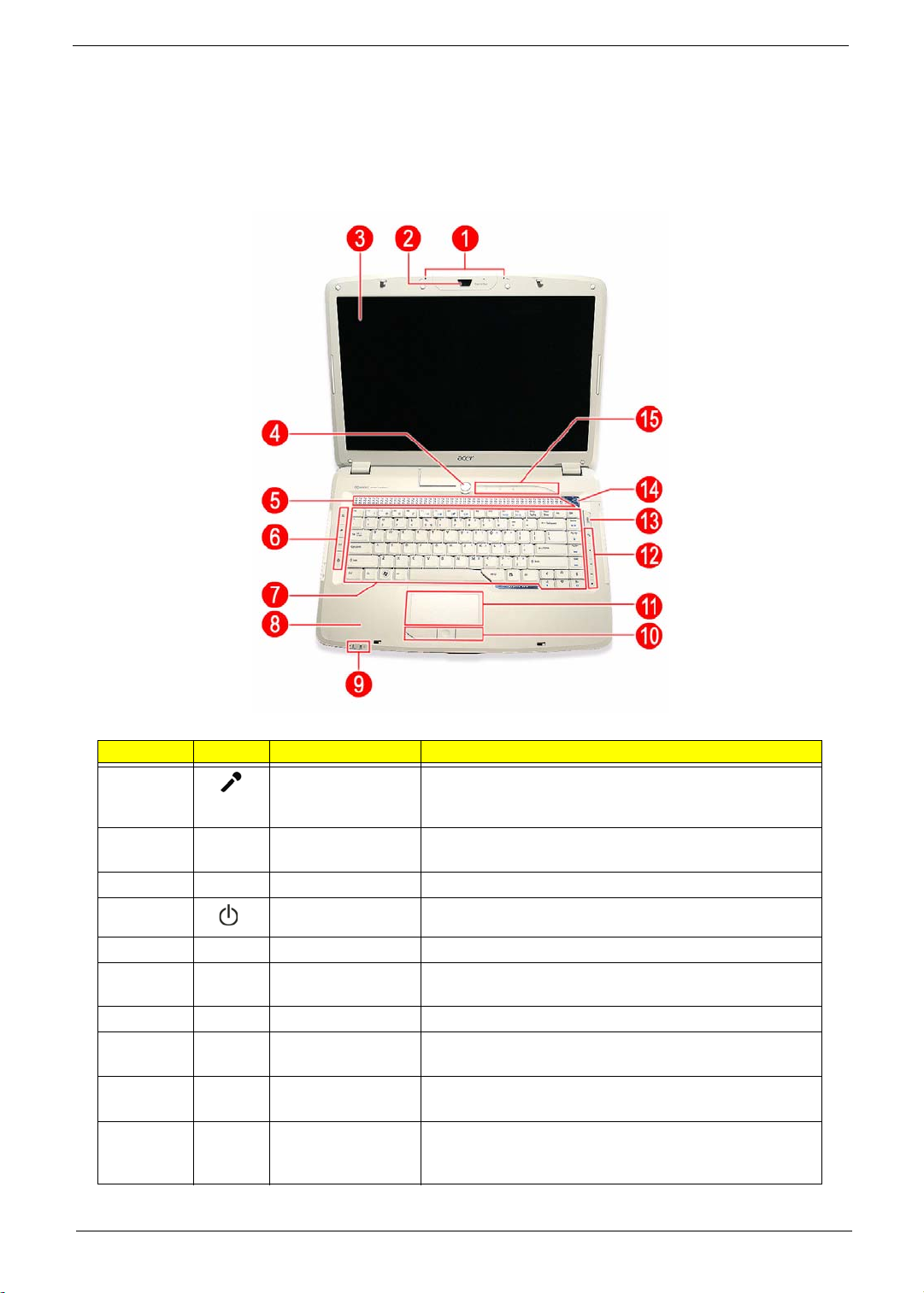
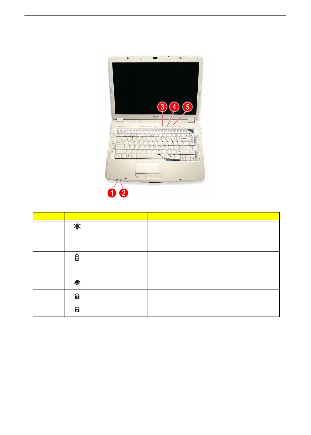
This section is a virtual tour of your Aspire notebook’s interior and exterior components.
Open Front View
Number Icon Item Description
1 Internal microphone Create sound recording and conduct voice
communication. Supports Acer PureZone audio
technology.
2 Acer OrbiCam
camera
3 LCD panel Displays computer output.
4 Power button Turns the computer on and off.
5 Speaker grill Delivers Dolby-quality audio output.
6 Easy-launch buttons Press to launch frequently used programs/function. Use
7 Keyboard For entering data into your computer.
8 Palmrest Comfortable support area for your hands when you use
9 Status indicators Light-Emitting Diodes (LEDs) for monitoring the power
10 Click buttons The left and right buttons function like the left and right
Chapter 1 5
Conduct video communication. (for selected models)
Launch Manager to configure these keys.
the keyboard.
status and battery charge level.
mouse buttons; the center button serves as a 4-way scroll
button.
Page 14
Number Icon Item Description
Note:
11 Touchpad Touch-sensitive pointing device which functions like a
computer mouse.
12 Acer MediaTouch
keys
13 Acer Arcade key Press to launch the Acer Arcade program.
For controlling playback in multimedia programs,
including in Acer Arcade.
14 Acer Empowering
key
15 Status indicators LEDs for monitoring the HDD activity, as well as the Num
Press to launch the Acer Empowering Technology
widgets.
Lock and Caps Lock functions.
Close Front View
Number Icon Item Description
1 Line-in jack Accepts audio line-in devices (e.g., audio CD player,
stereo walkman).
2 Microphone-in jack Accepts an external microphone.
3 Headphone jack Accepts audio line-out devices (e.g., speakers,
headphones). S/PDIF support provided.
4 Volume control Adjust the system audio-out volume .
5 Lid latch Locks and releases the notebook lid.
6 5-in-1 card reader
slot
7 IR port Interfaces with Infrared devices (e.g. infrared printer,
6 Chapter 1
Accepts MS, MS PRO, MMC, SD, and xD formats
memory cards.
IR-aware computers).
Note: In Bluetooth-enabled models, this is where the
Bluetooth board is located.
Page 15
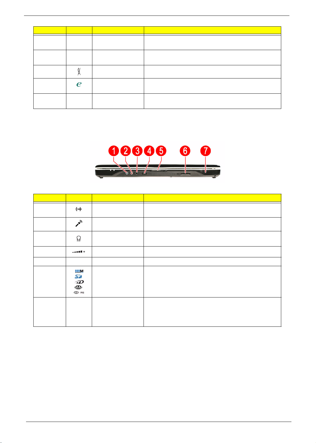
Left View
Number Icon Item Description
1 Kensington lock
hatch
2 Ethernet port (RJ-45) Connects to an Ethernet 10/100/1000-based network
3
4 VGA port Connects to an external display device (e.g., external
5 S-Video/TV-out port Connects to a television or display device with an S-video
6 USB 2.0 ports Connects to USB 2.0 devices (e.g. USB mouse, USB
7 IEEE 1394 ports Connects to a IEEE 1394 devices.
DVI-D
DVI-D port Connects to a display device with DVI-D input.
Accepts a Kensington-compatible computer security lock.
(selected models).
monitor, LCD projector).
input. Supports both NTSC and PAL standards.
camera).
8 ExpressCard/54 slot Accepts an ExpressCard/54 module.
Right View
Number Icon Item Description
1 Optical disc drive
(ODD)
2 ODD access indicator * Lights up when a the optical drive is active .
3 ODD eject button * Ejects the optical disc from the drive.
4 Emergency eject hole * Ejects the ODD tray when the computer is turned off.
5 USB 2.0 ports Connects to USB 2.0 devices (e.g. USB mouse, USB
6 Modem port (RJ-11) Connects to a phone line.
Accepts CDs or DVDs (drive type maybe slot-load or
tray-load depending on model).
camera).
* Item location varies depending on the drive model.
Chapter 1 7
Page 16
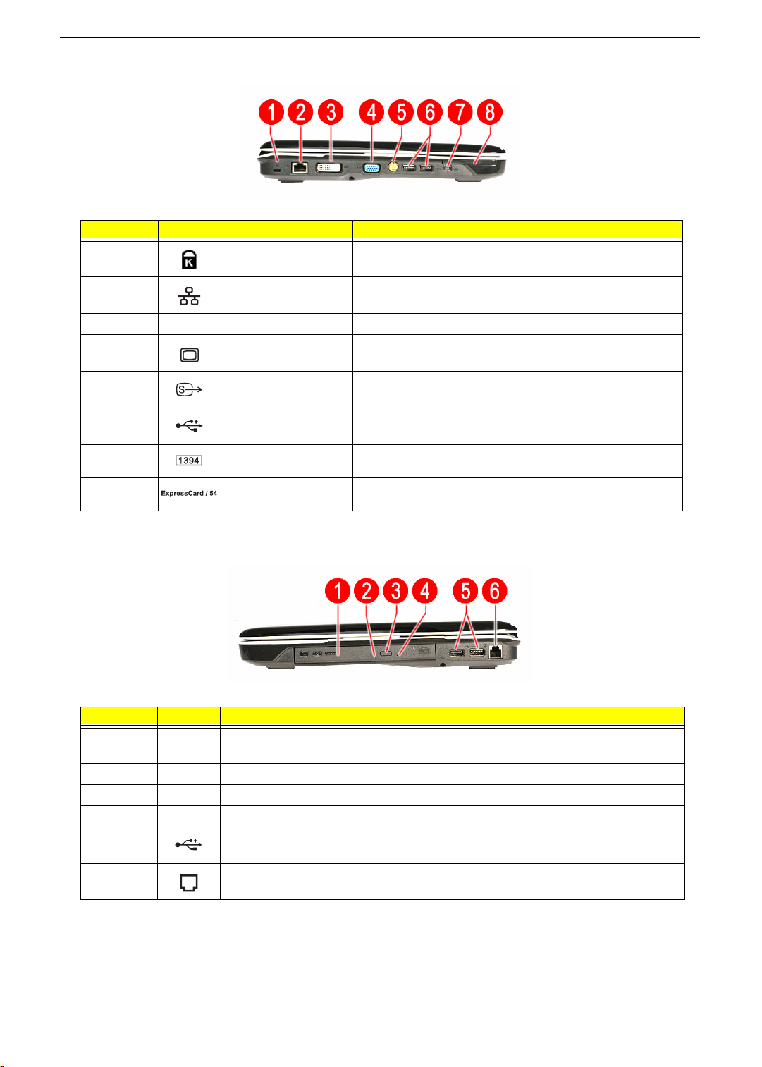
Rear View
Number Icon Item Description
1 AC power indicator Lights up blue when the AC adapter is connected to the
DC-in jack (AC power mode).
2 DC-in jack Connects to an AC adapter.
2 Ventilation slots Enable the computer to stay cool, even after prolonged
use.
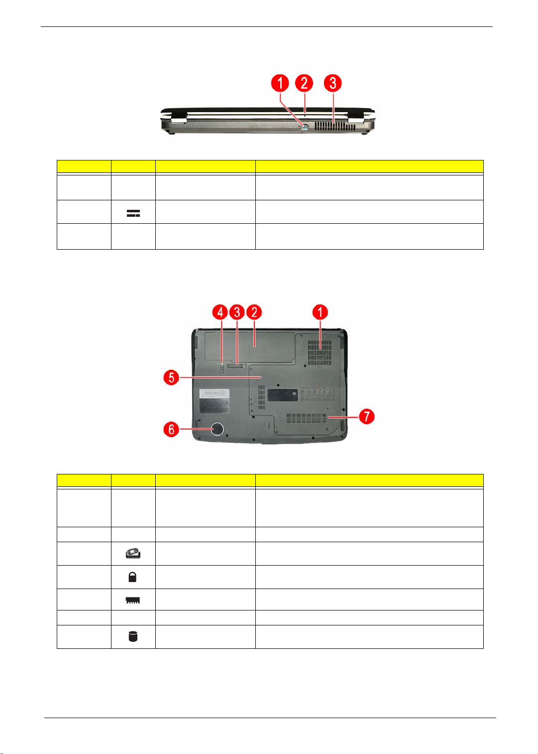
Base View
Number Icon Item Description
1 Ventilation slots and
cooling fan
2 Battery pack Provides power to the computer.
3 Battery release latch Releases the battery pack for removal.
4 Battery lock Secures the battery pack in position.
5 Memory compartment Houses the computer's main memory.
6 Subwoofer Emits low frequency sound output.
7 HDD compartment Houses the computer's hard disk drive.
8 Chapter 1
Enable the computer to stay cool, even after prolonged
use.
Note: Do not cover or obstruct the opening of the fan.
Page 17
Status Indicators
The computer has several status indicators for monitoring various system components and functions.
Number Icon Indicator Description
1 Power Indicates the computer’s power state. It lights up:
T Blue when the computer is powered on.
T Flashing orange when the computer is in standby or
hibernation mode.
2 Battery charge Indicates the battery charging state. It lights up:
T Orange when the computer is charging.
T Green when the computer is in AC mode.
3 Hard drive activity Flashes blue when there is hard drive activity.
4 Num Lock Lights up blue when the Num Lock function is activated.
5 Caps Lock Lights up blue when the Caps Lock function is activated.
Chapter 1 9
Page 18
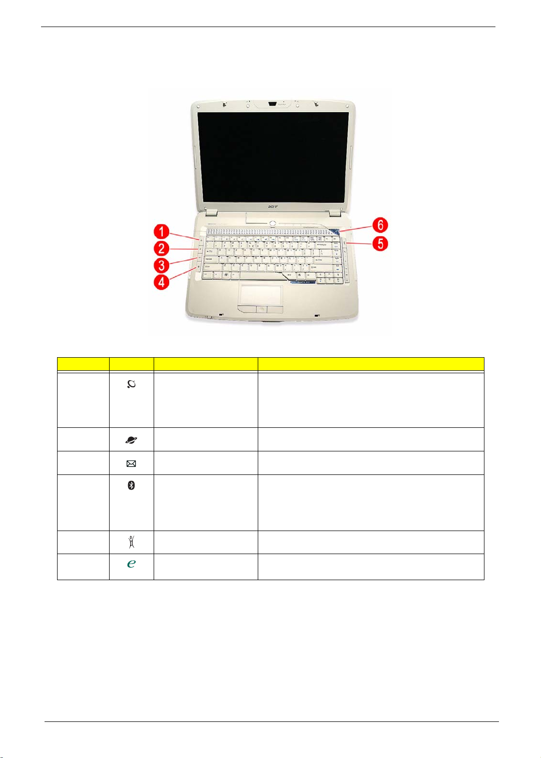
Easy-launch Keys
On the left and right side of the keyboard are special keys for launching commonly-used programs.
Number Icon Indicator Description
1 WLAN key/indicator Press to enable/disable the wireless LAN function.
This key also indicates the WLAN status. It lights up:
T Blue when there is an active WLAN connection
T Orange when there is no WLAN connection.
2 Web browser * Press to launch the preferred Internet browser.
3 Mail * Press to launch the preset E-mail application.
4 Bluetooth key/indicator * Press to enable/disable the Bluetooth function.
This key also indicates the Bluetooth status. It lights up:
T Blue when there’s an active Bluetooth connection
T Orange when there’s no Bluetooth connection.
5 Acer Arcade key Press to launch the Acer Arcade program.
6 Acer Empowering key * Press to launch the Acer Empowering Technology
widgets.
* These keys are user-programmable. Run Launch Manager to configure them. Go to page 22 for instructions.
10 Chapter 1
Page 19

Chapter 2
System Utilities
Phoenix TrustedCore Setup Utility
Phoenix TrustedCore Setup Utility is a hardware configuration program built into your system's Basic Input/
Output System (BIOS). Since most systems are already properly configured and optimized, there is normally
no need to run this utility.
You will need to run this utility under the following conditions:
T When changing the system configuration including:
t Setting the system time and date
t Configuring the hard drives
t Specifying the boot device sequence
t Configuring the power management modes
t Setting up system passwords or making other changes to the security setup
T When a configuration error is detected by the system and you are prompted (“Run Setup” message) to
make changes to the BIOS settings.
IMPORTANT: If you repeatedly receive “Run Setup” messages, the RTC battery located on the system
board (RTC1) may be defective. In this case, the system cannot retain configuration values in
CMOS. Replace the RTC battery with a new one.
NOTE: For ease of reading, Phoenix TrustedCore Setup Utility will be simply referred to as “Setup” or “Setup
Utility” in this Service Guide.
The screenshots used in this guide display default system values. These values may not be the same
as those in your computer.
In the descriptive tables following each of the menu screen illustrations, settings in boldface are the
default and suggested parameter settings.
The Setup Utility loads the configuration values in a battery-backed nonvolatile memory called CMOS RAM.
This memory area is not part of the system RAM, which allows configuration data to be retained when power is
turned off. The values take effect when the system is booted. Power-On Self Test (POST) uses these values to
configure the hardware. If the values and the actual hardware do not agree, POST generates an error
message. You must run this utility to change the BIOS settings from the default or current configuration.
Chapter 2 11
Page 20
Accessing the Setup Utility
1. Turn on the computer.
If the computer is already turned on, save your data and close all open applications, then restart the
computer.
2. During POST, press F2.
If you fail to press F2 before POST is completed, you will need to restart the computer.
The first page to be displayed will be the Information menu. Use the left ( ) and right ( ) arrow keys to
move between selections on the menu bar.
Menu bar
Legend bar
12 Chapter 1
Page 21
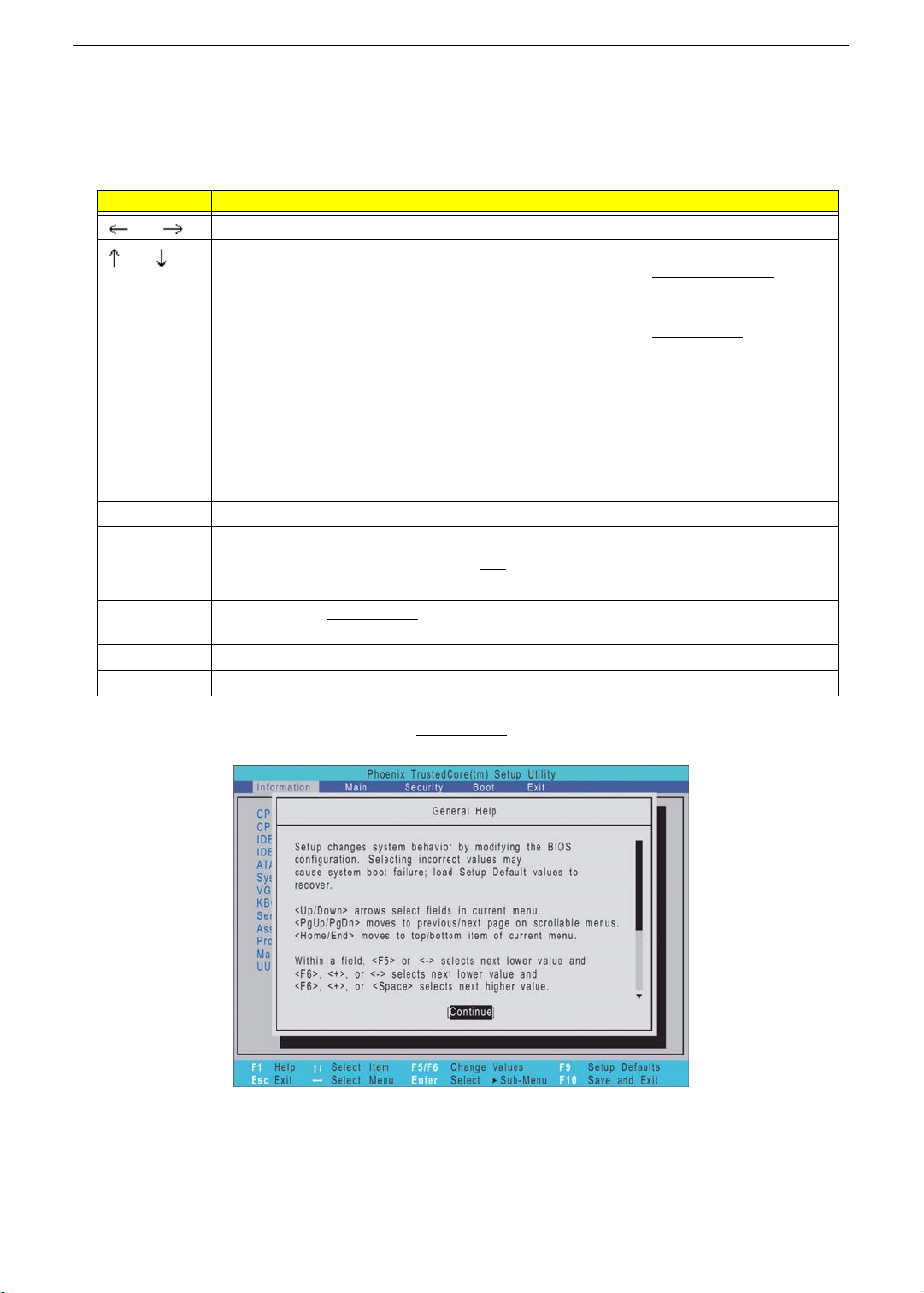
Navigating Through the Setup Utility
Use the keys listed in the legend bar on the bottom of the Setup screen to work your way through the various
menu and submenu screens of the Setup Utility. The table below lists these legend keys and their respective
functions.
Key Function
and To move between selections on the menu bar.
and
F5 or (-)
F6, (+), or
Space
Enter To select a field value.
Esc or Alt-X If you press this key:
F1 or Alt-H To bring up the General Help
F9 Press to load default system values.
F10 Press to save changes and close the Setup Utility.
To move the cursor to the field you want.The currently selected field will be highlighted.
The right side of each menu screen displays a field help panel—Item Specific Help
This panel displays the help text for the currently selected field. It updates as you move
the cursor to each field.
You can also use these keys to navigate through the multipage General Help
window.
To select a value for the curre ntly selected field (only if it is user-config u rab l e ). P ress F5
or (-) to select the next lower value; F6, (+), or Space to select the next higher value.
A parameter that is enclosed in square brackets [ ] is user-configurable. Parameters are
not user-configurable for one of the following reasons:
T The field value is auto-configured or auto-detected.·
T The field value is informational only.
T The field is password-protected.
T On one of the menu screens, the Exit menu displays.
T On a General Help window, closes the window.
window. This window lists other Setup navigation keys that
are not displayed on the legend bar.
panel.
Additional help information is available on the General Help window. Just press F1 on any screen.
Chapter 1 13
Page 22
Setup Utility Menus
The PhoenixBIOS Setup Utility has five menus for configuring the various system functions. These include:
• Information
•Main
• Security
• Boot
• Exit
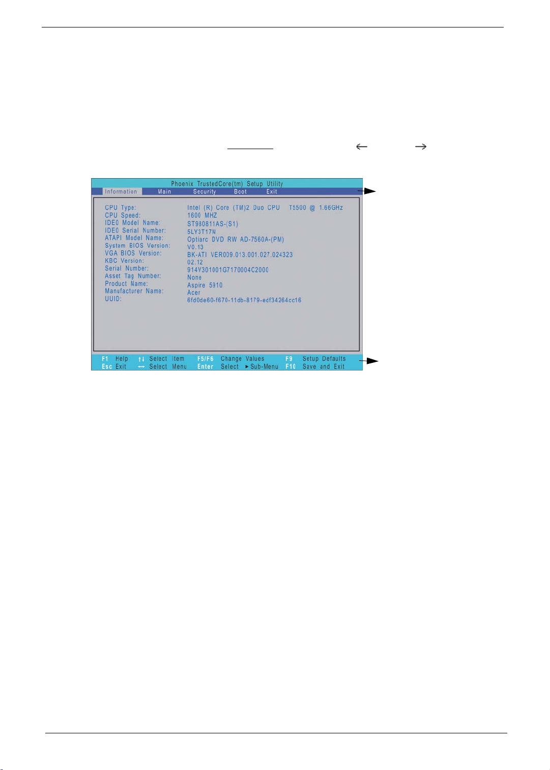
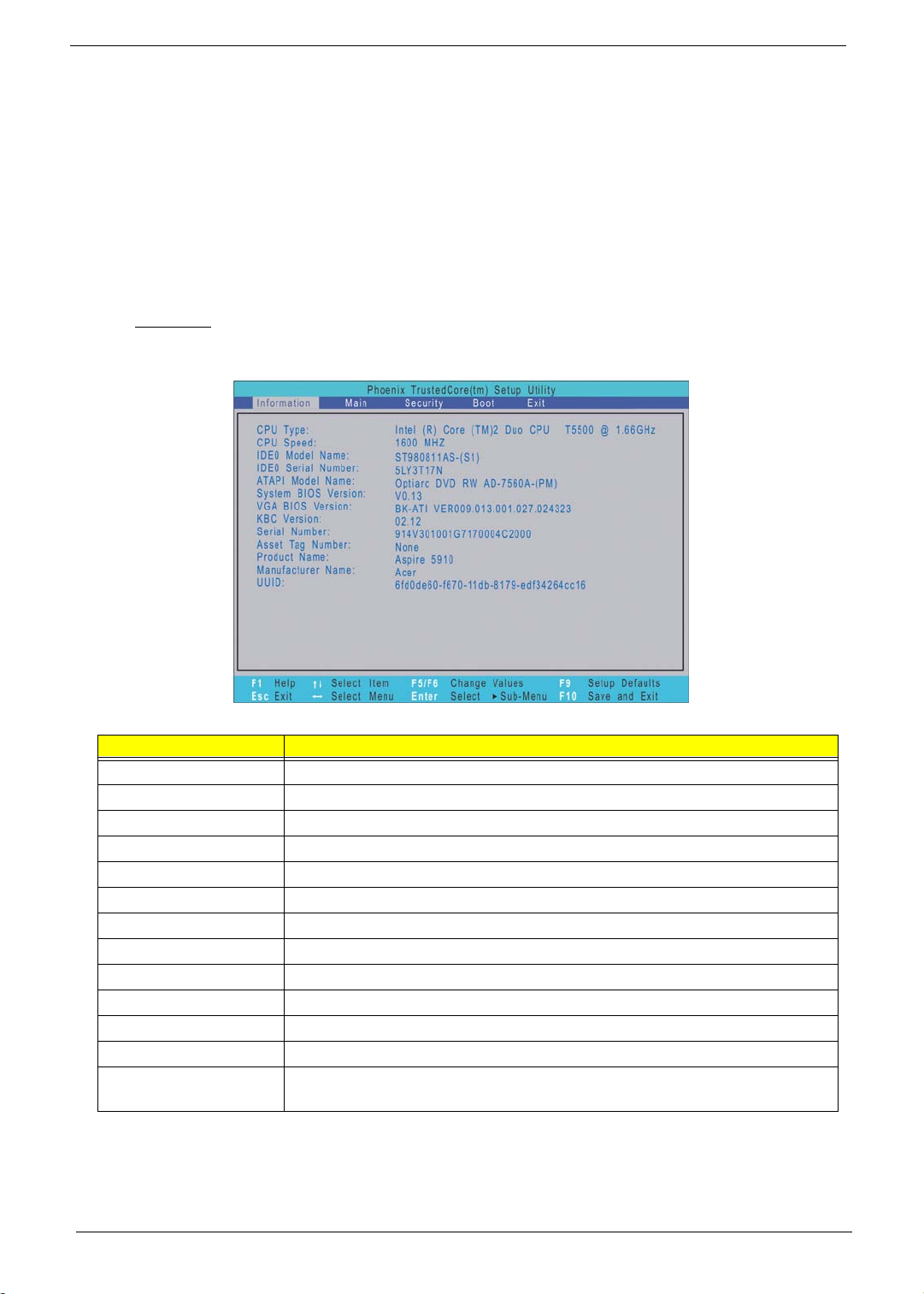
Information
The Information menu screen displays a summary of your computer hardware information. These information
are necessary for troubleshooting and may be required when asking for technical support.
Field Description
CPU Type Displays the processor name, sequence number, and clock speed.
CPU Speed Displays the CPU speed.
IDEO Model Name Displays the hard disk drive model.
IDEO Serial Number Displays the hard disk drive serial number.
ATAPI Model Name Displays the optical disc drive model.
System BIOS Version Displays the current system BIOS version.
VGA BIOS Version Displays the current VGA firmware version.
KBC Version Displays the current keyboard controller version.
Serial Number Displays the system serial number.
Asset Tag Number Displays the system asset tag number
Product Name Displays the official model name of the product.
Manufacturer Name Displays the manufacturer of the computer.
UUID Displays the universally unique identifier of your computer. This will only be
visible when an internal LAN device is presenting.
14 Chapter 1
Page 23
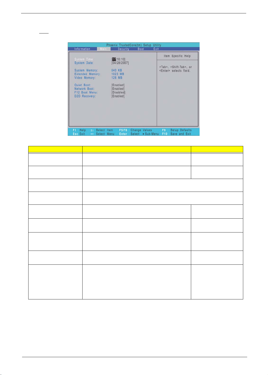
Main
The Main menu screen allows you to configure the basic system settings and view the memory allocations.
Field Description Value
System Time Set the system time. HH:MM:SS
(hour:minute:second)
System Date Set the system date. MM/DD/YYYY
(month/day/year)
System Memory Displays the size of system memory detected during boot-up. Memory size is
fixed at 640 MB.
Extended Memory Displays the size of extended memory detected during boot-up. Extended
memory size is equal to total memory size less 1 MB.
Video Memory Displays the size of video memory detected during
boot-up.
Quiet Boot When enabled, the Acer logo screen appears
during boot-up
Network Boot When enabled, remote host with appropriate boot
image can boot this computer. (Only works with an
Ethernet device.)
F12 Boot Menu When enabled, the “Press F12 to enter Multi-Boot
Menu” message is displayed during POST.
D2D Recovery When enabled, pressing Alt-F10 during POST will
activate the Acer disc-to-disc recovery function.
The function allows the user to create a hidden
partition on the hard drive to store a copy of the OS
and restore the system to its default factory
settings.
128 MB
256 MB
Disabled
Enabled
Disabled
Enabled
Disabled
Enabled
Disabled
Enabled
Chapter 1 15
Page 24
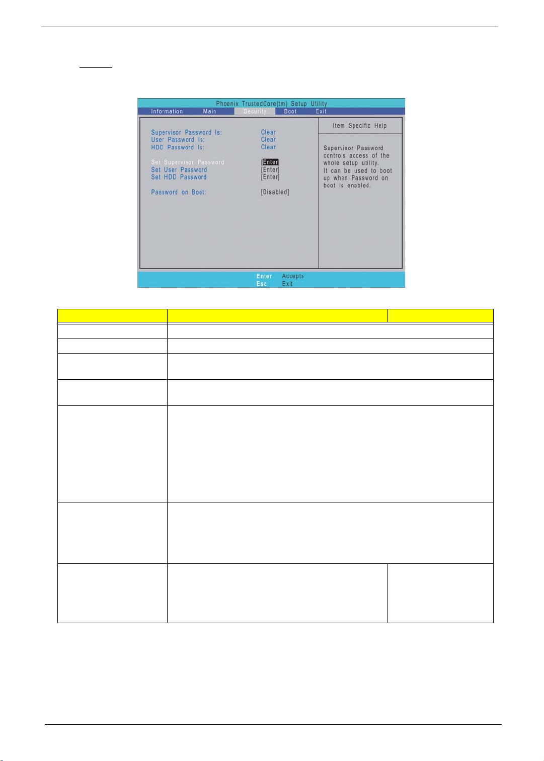
Security
The Security menu screen displays system passwords options to help safeguard and protect your computer
from unauthorized use.
Field Description Value
Supervisor Password Is Indicates whether a supervisor password is in use (Set) or not (Clear).
User Password Is Indicates whether a user password is in use (Set) or not (Clear).
HDD Password Is Indicates whether an HDD password is in use (HDD Password Set) or not
(Clear).
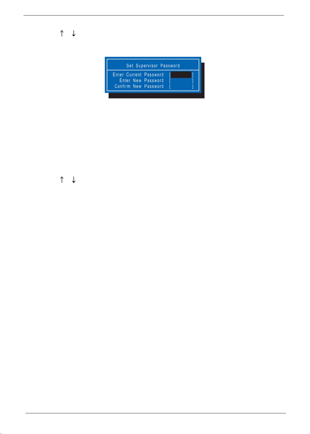
Set Supervisor
Password
Set User Password When set, this password will restrict a user’s access to the Setup menus. Only
Set HDD Password W hen set, this password will restrict a user’s access to the internal hard disk
Password on Boot Referred to as power-on password. When set, the
When set, this password will allow the user to access and change all settings
in the Setup Utility. Press Enter to configure.
the following menus will be accessible:
T System Time
T System Date
T Boot menu options
T All Exit menu options excluding Load Setup Defaults
A supervisor password must first be set before creating a user password.
drive. It will be required during boot-up or when resuming from S4 mode
(hibernation).
Note: If this password is the same as the power-on password, it will not be
required anymore at boot-up.
Disabled
user or supervisor password will be required to boot
Enabled
up the system or when resuming from S4 mode. A
supervisor password must first be set before
creating this password.
16 Chapter 1
Page 25
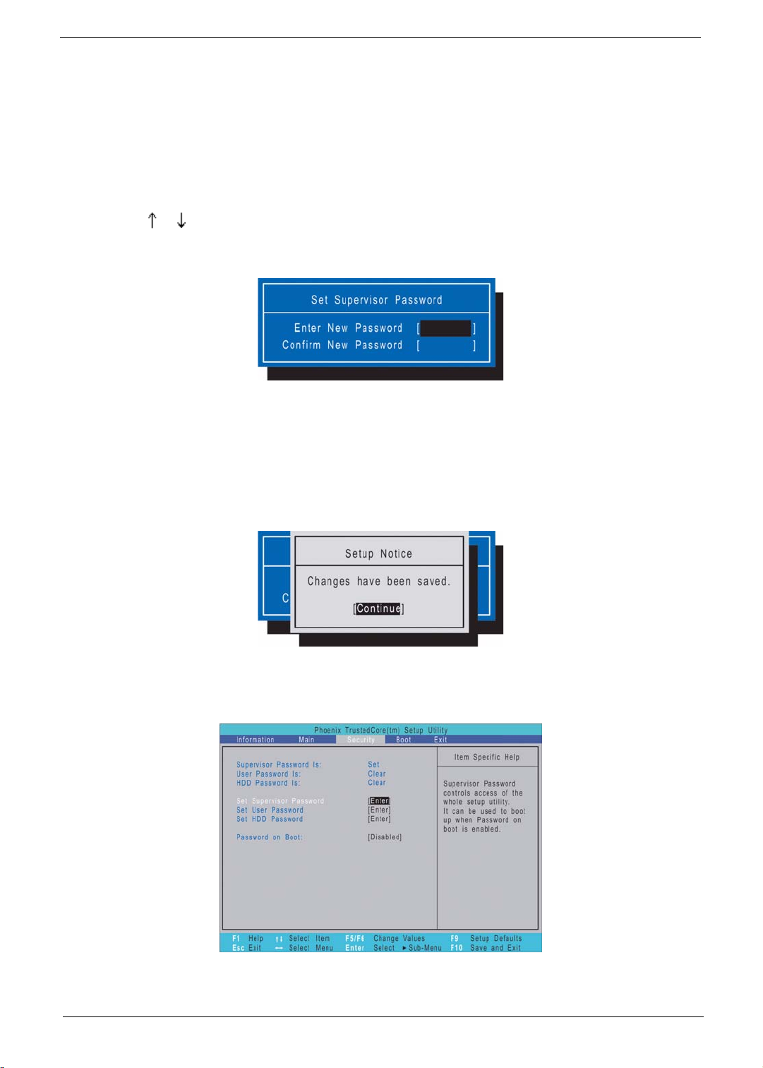
Setting a system password
Note the following before you define a system password:
• The maximum length of password contains eight alphanumeric characters—A - Z, 0 - 9, and ‘;’
(for a French keyboard).
• System passwords are case-insensitive.
• Password re-try is limited to three times. If user failed to enter the correct password, the system will
hang up.
T o set a system password:
1. Press or to highlight a set password field, then press Enter.
The password box appears.
2. Type a password then press Enter.
IMPORTANT: Be very careful when typing your password because the characters do not appear on the
screen. Only shaded blocks representing each typed character are visible.
3. Retype the password to verify the first entr y, then press Enter.
You will be prompted to save the new password.
4. Press Enter.
The corresponding password status field displays Set to indicate that a password has been enabled.
5. Press F10 to save the password and close the Setup Utility.
Chapter 1 17
Page 26
T o change a system password:
1. Press or to highlight an enabled password field, then press Enter.
The password box appears.
2. Type the original password, then press Enter.
3. Type a new password, then press Enter.
4. Retype the new password to verify the first entry, then press Enter.
You will be prompted to save the new password.
5. Press Enter.
6. Press F10 to save the password and close the Setup Utility.
To remove a system password:
1. Press or to highlight a password parameter, then press Enter.
The password box appears.
2. Type the original password, then press Enter.
3. Press Enter twice without entering anything in the new and confirm password fields.
You will be prompted to confirm the password removal.
4. Press Enter.
The corresponding password status field displays Clear to indicate that the password has been disabled.
5. Press F10 to save the changes you made and close the Setup Utility.
To clear a lost password:
If you have forgotten the user password, the computer will continue to function normally but you will have
limited access to the Setup Utility.
If you have enabled the Password on Boot field and you forget the supervisor password, you will not be able to
boot up the computer. The same thing applies if you forget an HDD password. You will need to clear the lost
password by shorting the SW1 dip switch located near the DIMM slot (DM1).
Perform the following procedure to clear all the system passwords (user , supervisor, and HDD).
1. Turn off the computer and unplug all the peripherals connected to it.
2. Unplug the power cord from the computer.
3. Remove the lower case cover according to the instructions described on page 28.
4. Remove the memory modules according to the instructions described on page 29.
18 Chapter 1
Page 27
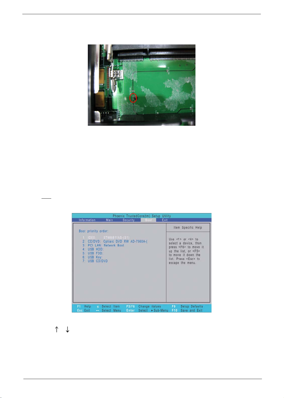
5. Peel off the black tape near the DIMM slot to expose the SW1 dip switch.
6. Locate the SW1 dip switch (G55).
7. Position the SWI dip switch to ON to clear all system passwords.
8. Reinstall the memory modules and the lower case cover.
9. Turn on the computer and press F2 during bootup to access the Setup Utility.
10. Press F9 to load the system defaults.
11. Press F10 to save the changes you made and close the Setup Utility.
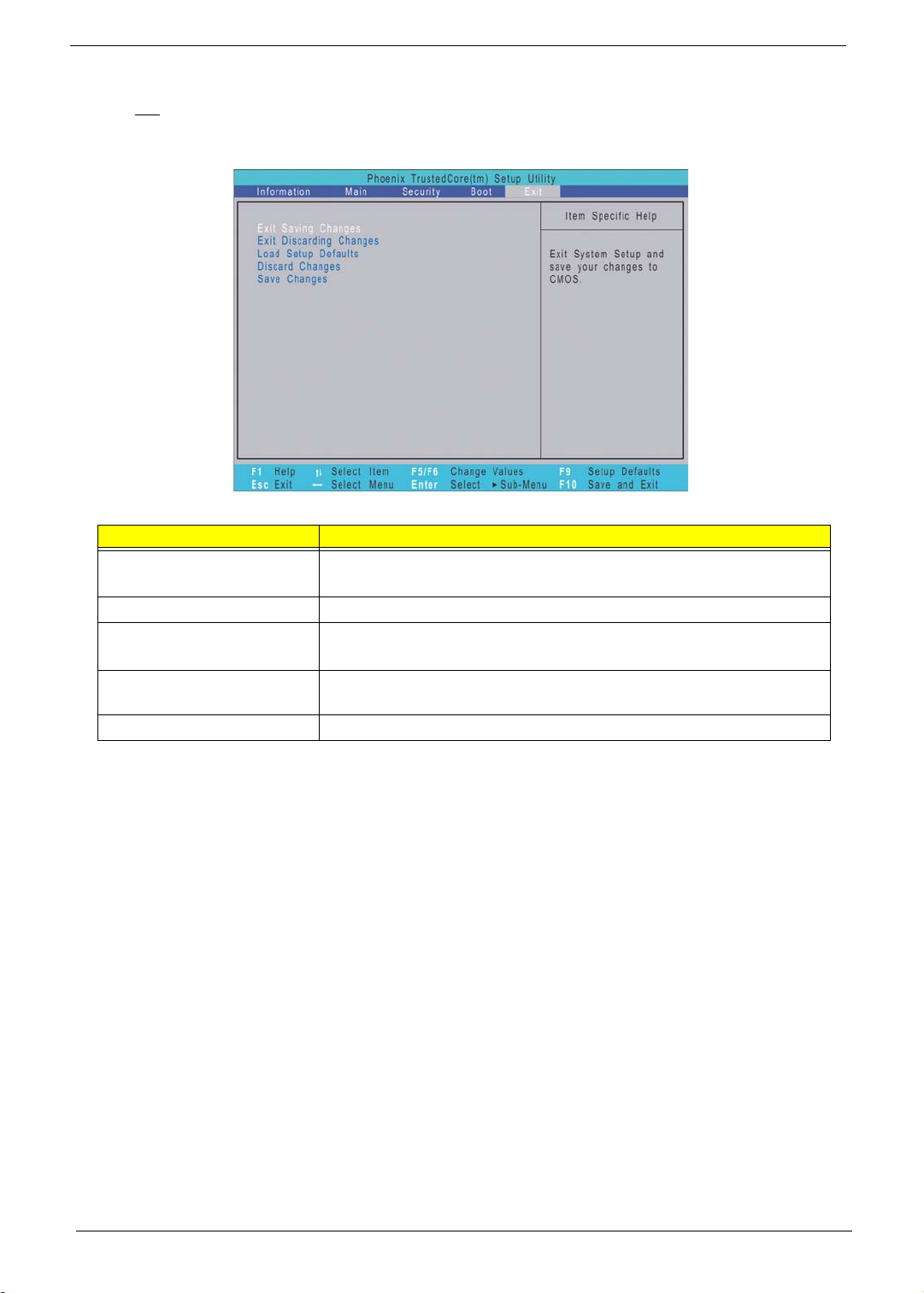
Boot
The Boot menu screen allows users to set the drive sequence in which Setup attempts to boot the operating
system. By default, Setup searches for boot devices in the order shown in the screen below.
To set the boot drive sequence:
1. Press or to select a bootable device.
2. Press F6 to move the device up the list, or F5 to move it down the list.
3. Press F10 to save the changes you made and close the Setup Utility.
Chapter 1 19
Page 28
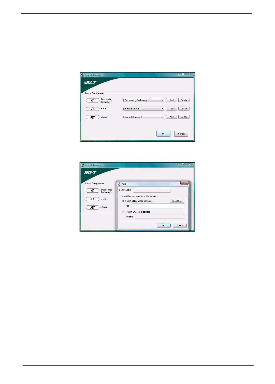
Exit
The Exit menu displays the several options on how to quit from the Setup Utility. Select any of the exit options
then press Enter.
Option Description
Exit Saving Changes Saves changes made and closes the Setup Utility.
Keyboard shortcut: F10·
Exit Discarding Changes Discards changes made and closes the Setup Utility.
Load Setup Defaults Loads the factory-default settings for all Setup fields.
Keyboard shortcut: F9
Discard Changes Discards all changes made to the Setup Utility and loads the previous
configuration settings.
Save Changes Saves all changes made to the Setup Utility.
20 Chapter 1
Page 29

BIOS Flash Utility
The BIOS flash memory update is required under the following conditions:
T When there are new versions of system programs
T When new hardware options are installed
T When the BIOS has been corrupted and you need to restore it
BIOS Flash Precautions
T If you do not have a crisis recovery diskette at hand, create a Crisis Recovery Diskette in Windows XP
of Vista before you use the flash utility.
T Do not install memory-related drivers (XMS, EMS, DPMI) when you use the flash utility.
T Place the computer in AC mode during the BIOS flash procedure. If the battery pack does not contain
enough power to finish the BIOS flash, you may not able to boot the system because the BIOS is not
completely loaded.
To flash the BIOS:
1. Prepare a bootable diskette.
2. Copy the flash utilities to the bootable diskette.
3. Boot the system from the bootable diskette.
The flash utility will automatically be executed.
4. Follow the on-screen instructions to finish the flashing of the BIOS.
BIOS Recovery
If a BIOS flash procedure fails to complete, perform a BIOS recovery procedure by using the Crisis Recovery
Diskette. During this procedure, the system will force the BIOS to enter a special BIOS block, called boot
block, to boot up the system with minimum BIOS initialization.
To perform BIOS recovery:
1. Make sure the power cord is connected to the computer.
1. Attached a USB floppy drive to th e co mp ut er.
2. Insert the Crisis Recovery Diskette into the floppy drive.
3. Press and hold the Fn+Esc keys, then press the power button .
This initialize the BIOS recovery process. The boot block BIOS will start to restore the failed BIOS code.
Short beeps should be heard during this process. Once the process is completed, a long be ep should be
heard.
4. Turn off the computer once the process is complete.
5. Turn on the computer again and flash the BIOS. Refer to the previous instructions.
Chapter 1 21
Page 30
Launch Manager
Launch Manager allows users to configure three of the easy-launch keys—Acer Empowering, Web browser,
and Mail.
To configure an easy-launch key:
1. Select Start | All Programs | Launch Manager.
2. Select which key to configure, then click the Add button opposite it.
3. You can set the key to open a particular file or program, or display a Web site address. Select the
corresponding radio button, then type or browse for your selection.
4. If you’ve entered a Web site address, key in a descriptive label for the new easy-launch key function.
5. Click OK.
6. Click OK to save the new settings.
22 Chapter 1
Page 31

System Disassembly
This chapter provides step-by-step instructions on how to disassemble the notebook computer for
maintenance and troubleshooting purposes.
Disassembly Tools
In performing the disassembly process, you will need the following tools:
T Wrist-grounding strap and conductive mat for preventing electrostatic discharge
T Philips screwdriver
T Flat screwdriver
T Hex screwdriver
T Flat plastic screwdriver
T Plastic tweezers
Stages of the Disassembly Process
The disassembly process is divided into three stages:
1. External modules disassembly
2. Main unit disassembly
a. Upper case disassembly
b. Lower case disassembly
3. LDC module disassembly
Chapter 3
IMPORTANT: The disassembly procedure described in this chapter is a gradual process, as illustrated in the
flowcharts preceding each disassembly stage section. This means that users need to observe
the instructions in a step-by step manner. T o illustrate, removing the HDD assembly will require
that you first remove the battery pack and the stylus. Failure to observe the gradual flow of the
process may result in component damage.
NOTE: To reinstall the system components and assemble the unit, perform the disassembly procedures
in reverse.
Equivalent Torque Values
Torque values indicated in this chapter are expressed in kgf-cm (kilogram force-centimetre). For equivalent
values in in-lb (inch-pound force) and Nmm (milli Newton meter), refer to the table below.
Torque Units kgf-cm in-lb Nmm
1.6 1.39 156.91
Torque
values
32.60294.21
43.47392.28
Chapter 3 23
Page 32

System Screw List
Listed below are the screw types used in this system, plus their corresponding part numbers.
NOTE: The screws for the different components vary in size. During the disassembly process, group the
screws with their corresponding components to avoid mismatches when putting back the components.
Screw Type Color Part Number
A M2 x L8 BZN+NYLOK Black 86.00D75.220
B M2 x L4 BZN Black 86.00A02.140
C M2.5 x L8 BZN+NYLOK Black 86.00E34.738
D M2 x L4 BZN+NYLOK Black 86.00E13.524
E M3 x L4 Silver 86.9A554.4R0
F M2 x L3 BZN+NYLOK Black 86.00E25.723
G M2 x L2.5 BZN+NYLOK Black 86.00D72.620
H M2.5 x L12 BZN+NYLOK Silver 86.00E67.63C
I M2.5 x L4 BZN+NYLOK Black 86.00D30.630
J M2.5 x L6 BZN+NYLOK Black 86.00E33.736
K M2 X L2 NI Silver 86.00D77.320
L M2.5 x L5 BZN+NYLOK Black 86.00F19.735
M M2.5 x L3 BZN+NYLOK Black 86.00D52.630
Pre-disassembly Procedure
Before proceeding with the disassembly procedure, perform the steps listed below:
1. Turn off the power to the computer and all peripherals.
2. Unplug the power cord from the co mputer.
3. Unplug all peripheral cables from the computer.
4. Close the notebook lid and place the computer on a flat, steady surface.
24 Chapter 1
Page 33

External Modules Disassembly
(
)
External Modules Disassembly Flowchart
Turn off
computer and
disconnect
power c ord
SD dummy card
EXpressCard
dummy card
Battery pack
L-case cover
(Ax1, Bx7, Cx1)
DIMM
WLAN board
(Dx2)
Screw Type Part Number
A M2 x L8 BZN+NYLOK 86.00D75.22 0
B M2 x L4 BZN 86.00A02.140
C M2.5 x L8 BZN+NYLOK 86.00E34.738
D M2 x L4 BZN+NYLOK 86.00E13.524
E M3 x L4 86.9A554.4R0
F M2 x L3 BZN+NYLOK 86.00E25.723
G M2 x L2.5 BZN+NYLOK 86.00D72.620
HDD assembly
Hard drive
shielding
Ex2
Hard drive
module
ODD assembly
ODD bracket
(Cx1)
ODD module
(Fx2)
Fan
(Dx1)
Heat sink
(Dx4, Gx5)
Processor
VGA board
(Fx2)
Chapter 1 25
Page 34

Removing the SD Dummy Card
1. Push against the card, as if you were pushing it further into the slot, letting the card spring out.
2. Pull the SD dummy card out of its slot.
Removing the ExpressCard/54 Dummy Card
1. Push against the card, as if you were pushing it further into the slot, letting the card spring out.
26 Chapter 1
Page 35

2. Pull the ExpressCard/54 dummy card out of its slot.
Removing the Battery Pack
1. Turn the unit over with the base facing upward.
2. Slide the battery lock to the unlock position.
3. Slide the battery release latch to pop up the battery from its bay.
Chapter 1 27
Page 36

4. Remove the battery pack from its bay.
Removing the Lower Case Cover
1. Remove the screws securing the lower case cover.
Step Type Quantity Color Torque
1 M2 x L8 BZN+NYLOK 1 Black 1.6 kgf-cm +/-15%
M2 x L4 BZN 7 Black 1.6 kgf-cm +/-15%
M2.5 x L8 BZN+NYLOK 1 Black 3 kgf-cm +/-15%
2. Pry the lower case cover from the main unit, the n remove it.
28 Chapter 1
Page 37

Removing the Memory Modules
1. Push out the latches on both sides of the exterior DIMM slot (DM1).
2. Remove the memory module from its slot.
3. Repeat steps 1 and 2 to remove the second memory module.
Removing the WLAN Board
1. Peel off the end of the bar code tape securing the WLAN antennas.
Chapter 1 29
Page 38

2. Disconnect the antennas from the WLAN board, then move them away from the board.
3. Remove the screws securing the WLAN board.
Step Type Quantity Color Torque
3 M2 x L4 BZN+NYLOK 2 Black 1.6 kgf-cm +/-15%
4. Remove the WLAN board from its slot (MINI1).
30 Chapter 1
Page 39

Removing and Dismantling the HDD Assembly
1. Partly peel off the mylar tape (1) and use it to pull the HDD assembly from its connector (2. SATA1).
2. Remove the HDD assembly from the main unit.
3. Remove the screws on the HDD module shielding.
Step Type Quantity Color Torque
3 M3 x L4 2 Silver 3 kgf-cm +/-15%
Chapter 1 31
Page 40

4. Remove the HDD module from its shielding.
Removing and Dismantling the ODD Assembly
1. Remove the screw securing the ODD assembly to the main unit.
Step Type Quantity Color Torque
1 M2.5 x L8 1 Black 3 kgf-cm +/-15%
2. Use a plastic flat screwdriver to push the ODD assembly out of the main unit, then slide it out of its bay.
32 Chapter 1
Page 41

3. Detach the ODD bracket by removing the screws that secure it to the ODD module.
Step Type Quantity Color Torque
3 M2 x L3 BZN+NYLOK 2 Black 1.6 kgf-cm +/-15%
Removing the Cooling Fan
1. Disconnect the fan cable from its system board connector (FAN1).
2. Remove the screw securing the fan.
Step Type Quantity Color Torque
2 M2 x L4 BZN+NYLOK 1 Black 1.6 kgf-cm +/-15%
Chapter 1 33
Page 42

3. Remove the fan from the main unit.
Removing the Heat Sink
1. Remove the screws securing the heat sink (Discrete model).
Step Type Quantity Color Torque
1 M2 x L4 BZN+NYLOK 4 Black 1.6 kgf-cm +/-15%
M2 x L2.5 BZN+NYLOK 5 Black 1.6 kgf-cm +/-15%
2. Carefully pull the heat sink from its base, then remove it from the system board.
34 Chapter 1
Page 43

Removing the Processor
1. Use a flat screwdriver to turn the processor socket lock to the counter-clockwise to the unlock position
(note the unlock icon).
Torque value: 3 kgf-cm +/-15%
2. Partly peel off the processor bar code tape.
3. Hold the processor by its edges and remove it from its socket (U36).
IMPORTANT: When installing a processor, note the golden arrow on the corner to make sure the processor is
properly oriented over the socket. Refer to figure above.
Chapter 1 35
Page 44

Removing the VGA Board
1. Remove the screws securing the VGA board to the system board.
Step Part Number and Type Quantity Color Torque
1 M2 x L3 BZN+NYLOK 2 Black 1.6 kgf-cm +/-15%
2. Hold the VGA board by its edges and pull it from its slot (MXM1).
36 Chapter 1
Page 45

Main Unit Disassembly
IMPORTANT: To prevent from scratching or damaging the LCD panel, cover it with a protective film before
disassembling the main unit.
Main Unit Disassembly Flowchart
Main unit
Keyboard Middle cover
LCD module
(Cx2, Hx2)
Power board
(Dx4)
Upper case
(Ix1 , Cx10, Jx2, Dx3) )
Power FPC cable
Speaker ca se
(Dx3, Kx3)
E-key board
(Fx3)
Launch board
(Dx2)
Touchpad board
bracket (Dx3)
Touchpad cable
Lower case
Modem board
(Fx2)
Bluetooth board
Subwoofer
USB board
(Dx1)
System board
(Dx2)
Card reader b oard
(Fx1)
Touchpad board
Screw Type Part Number
DC-in port
C M2.5 x L8 BZN+NYLOK 86.00E34.738
D M2 x L4 BZN+NYLOK 86.00E13.524
F M2 x L3 BZN+NYLOK 86.00E25.723
H M2.5 x L12 BZN+NYLOK 86.00E67.63C
I M2.5 x L4 BZ N+NYLOK 86.00D30.630
J M2.5 x L6 BZN+NYLOK 86.00E33.736
K M2 X L2 NI 86.00D77.320
Chapter 1 37
Page 46

Removing the Keyboard
1. Use a flat plastic screwdriver to push the six tabs securing the keyboard to the upper case (U-case).
2. Pry the keyboard off to release it from the upper case, then turn it over the palmrest to gain access to the
keyboard cable.
3. Disconnect the keyboard cable from its system board connector (KB1) to completely detach the keyboard
from the main unit.
38 Chapter 1
Page 47

Removing the Middle Cover
1. Open the LCD panel completely to facilitate the easy removal of the middle cover.
2. Use a plastic flat screwdriver to pry one end of the middle cover. Continue prying on the other side until
the cover is released from the U-case.
3. Remove the middle cover from the main unit.
Removing the LCD Module
1. Pull out the WLAN antennas from underneath the computer base, and then from under the speaker grill.
Chapter 1 39
Page 48

2. Disconnect the LCD and internal microphone cables from their system board connectors (LCD1,
INTMIC1).
3. Close the computer lid and turn the unit over to the base side.
4. Remove the lower case screws securi ng the LCD module.
Step Type Quantity Color Torque
4 M2.5 x L8 BZN+NYLOK 2 Black 3 kgf-cm +/-15%
5. Turn the unit right side up and open the notebook lid again.
6. Remove the hinge screws securing the LCD module.
Step Type Quantity Color Torque
6 M2.5 x L12 BZN+NYLOK 2 Silver 4 kgf-cm +/-15%
40 Chapter 1
Page 49

7. Detach the LCD module from the main unit.
Proceed to page 55 for instructions on how to disassemble the LCD module.
Removing the Power Board
1. Disconnect the power FPC cable from its power board connector (PWRCN1).
2. Remove the screws securing the power board.
Step Type Quantity Color Torque
2 M2 x L4 BZN+NYLOK 4 Black 1.6 kgf-cm +/-15%
Chapter 1 41
Page 50

3. Remove the power board from the upper case.
Removing the Upper Case
1. Disconnect the following system cables from their connectors.
t Empowering Key board cable (E_KEY1)
t Speaker cable (SPKR1)
42 Chapter 1
Page 51

t Power FPC cable (PWRCN1)
t Launch board cable (LAUNCHCN1)
t Touchpad cable (TPAD1)
t Media FPC cable (MEDIA1)
Chapter 1 43
Page 52

2. Turn the unit over to the base side.
3. Remove the lower case screws securing the upper case.
Step Type Quantity Color Torque
4 M2.5 x L4 BZN+NYLOK 1 Black 3 kgf-cm +/-15%
M2.5 x L8 BZN+NYLOK 10 Black 3 kgf-cm +/-15%
4. Turn the unit over again and remove the top upper case screws.
Step Type Quantity Color Torque
2 M2.5 x L6 BZN+NYLOK 2 Black 3 kgf-cm +/-15%
M2 x L4 BZN+NYLOK 3 Black 1.6 kg f-cm +/-15%
5. Pry the upper case from its lower case latches to remove it.
44 Chapter 1
Page 53

Removing the Power FPC Cable
T Remove the power FPC cable from the upper case.
Removing the Speaker
1. Remove the screws securing the speaker.
Step Type Quantity Color Torque
1 M2 x L4 BZN+NYLOK 3 Black 1.6 kgf-cm +/-15%
M2 X L2 NI 3 Silver 1.6 kgf-cm +/-15%
2. Remove the speaker from the lower case.
Chapter 1 45
Page 54

Removing the E-key Board
1. Disconnect the E-key board cable (E_KEY1).
2. Remove the screws securing the E-key board.
Step Type Quantity Color Torque
2 M2 x L3 BZN+NYLOK 3 Black 1.6 kgf-cm +/-15%
3. Remove the E-key board from the upper case.
46 Chapter 1
Page 55

Removing the Launch Board
1. Remove the screws securing the launch board.
Step Type Quantity Color Torque
1 M2 x L4 BZN+NYLOK 2 Black 1.6 kgf-cm +/-15%
2. Remove the launch board from the upper case .
Removing the Touchpad Board
1. Remove the screws securing the touchpad board bracket.
Step Type Quantity Color Torque
1 M2 x L4 BZN+NYLOK 3 Black 1.6 kgf-cm +/-15%
Chapter 1 47
Page 56

2. Detach the touchpad FPC cable from the upper case adhesive tape.
3. Remove the touchpad board bracket from the upper case.
4. Disconnect the touchpad FPC cable.
48 Chapter 1
Page 57

5. Carefully pry loose the touchpad board from the upper case to detach it.
CAUTION: The touchpad board is glued to the upper case. Remove the touchpad board only if it is defective.
Removing the Modem Board
1. Disconnect the Bluetooth cable from its system board connector (BLUE1).
2. Peel off the tape protecting the Bluetooth and modem cables.
Chapter 1 49
Page 58

3. Remove the screws securing the modem board.
Step Type Quantity Color Torque
3 M2 x L3 BZN+NYLOK 2 Black 1.6 kgf-cm +/-15%
4. Remove the modem board from its card reader board connector (MDC1), then disconnect the modem
cable from the board.
Removing the Bluetooth Board
T Remove the Bluetooth board from the lower case.
50 Chapter 1
Page 59

Removing the Subwoofer
1. Disconnect the subwoofer cable from its system board connector (SPKR2).
2. Remove the subwoofer from the lower case.
Removing the USB Board
1. Disconnect the USB FPC cable from its system board connector (USBCN1).
Chapter 1 51
Page 60

2. Disconnect the USB FPC cable from the its USB board connector.
3. Remove the screw securing the USB board.
Step Type Quantity Color Torque
3 M2 x L4 BZN+NYLOK 1 Black 1.6 kgf-cm +/-15%
4. Remove the USB board from the lower case.
52 Chapter 1
Page 61

Removing the System Board
1. Disconnect the DC-in cable from its system board connector (DC1).
2. Remove the screws securing the system board and the card reader board to the lower case.
Step Type Quantity Color Torque
2 M2 x L4 BZN+NYLOK 2 Black 1.6 kgf-cm +/-15%
3. Carefully remove the system board from the lower case.
Chapter 1 53
Page 62

Removing the Card Reader Board
1. Remove the screw securing the card reader board to the system board.
Step Type Quantity Color Torque
1 M2 x L3 BZN+NYLOK 1 Black 1.6 kgf-cm +/-15%
2. Turn the system board over, and detach the card reader board from its connector (CARDREADER1).
Removing the DC-in Jack
T Remove the DC-in jack from the lower case.
54 Chapter 1
Page 63

LCD Module Disassembly
LCD Module Disassembly Flowchart
LCD module
LCD bezel
(Jx6)
LCD panel
(Lx4, Dx2)
LCD panel brackets
(Fx6)
Screw Type Part Number
LCD chassis
Inverter board
LCD-CCD cable
LCD module hinge
(Lx2)
CCD bo ard
Internal microphone
WLAN antennas
(Mx1)
D M2 x L4 BZN+NYLOK 86.00E13.524
F M2 x L3 BZN+NYLOK 86.00E25.723
J M2.5 x L6 BZN+NYLOK 86.00E33.736
L M2.5 x L5 BZN+NYLOK 86.00F19.735
M M2.5 x L3 BZN+NYLOK 86.00D52.630
Chapter 1 55
Page 64

Removing the LCD Bezel
1. Remove the rubber pads securing the LCD bezel screws.
2. Remove the screws securing the LCD bezel.
Step Type Quantity Color Torque
2 M2.5 x L6 BZN+NYLOK 6 Black 3 kgf-cm +/-15%
3. Carefully pry the LCD bezel open and remove it from the LCD module.
56 Chapter 1
Page 65

Removing the LCD Panel
1. Remove the screws securing the LCD panel.
Step Type Quantity Color Torque
1 M2.5 x L5 BZN+NYLOK 4 Black 3 kgf-cm +/-15%
M2 x L4 BZN+NYLOK 2 Black 1.6 kg f-cm +/-15%
2. Disconnect the CCD board cable.
3. Remove the LCD panel from its chassis, then turn it over to gain access to the inverter board cables.
Chapter 1 57
Page 66

Removing the Inverter Board
T Disconnect the 2P and inverter cables from the inverter board.
Removing the LCD-CCD Cable
1. Peel off the acetic tapes securing the LCD-CCD cable to the LCD panel.
2. Disconnect the LCD connector end of the LCD-CCD cable from the LCD panel PCB.
58 Chapter 1
Page 67

Removing the LCD Panel Brackets
T Remove the screws securing the LCD panel brackets.
Step Part Number and Type Quantity Color Torque
* M2 x L3 BZN+NYLOK 6 Black 1.6 kgf-cm +/-15%
Removing the LCD Module Hinges
1. Remove the screws securing the LCD module hinges.
Step Type Quantity Color Torque
1 M2.5 x L5 BZN+NYLOK 2 Black 3 kgf-cm +/-15%
2. Remove the LCD module hinges from the LCD chassis.
Chapter 1 59
Page 68

Removing the CCD Board
T Remove the CCD board from the LCD chassis.
Removing the Microphones
1. Peel off the aluminum foil tabs and acetic tapes securing the microphone cables.
2. Carefully remove the internal microphones from the LCD chassis.
60 Chapter 1
Page 69

Removing the WLAN Antennas
1. Peel off the aluminum foil tabs securing the WLAN antennas.
2. Remove the screw securing the left antenna bracket.
Step Type Quantity Color Torque
2 M2.5 x L3 BZN+NYLOK 1 Black 3 kgf-cm +/-15%
3. Carefully detach the WLAN antenna from the LCD chassis.
Chapter 1 61
Page 70

62 Chapter 1
Page 71

Chapter 4
System Troubleshooting
This chapter provides instructions on how to troubleshoot system hardware problems. If the problem can’t be
resolved using the procedures described here, information for getting online technical assistance is also
provided.
Hardware Diagnostic Procedure
IMPORTANT: The diagnostic tests described in this chapter are only intended to test Acer products. Non-Acer
products, prototype cards, or modified options can give false errors and invalid system
responses.
1. Obtain as much detail as possible about the presented failure symptoms.
2. Verify the symptoms by attempting to re-create the failure through diagnostic tests or by repeating the
same condition that precedes the symptoms.
3. Refer the table below to determine whic h corrective action to perform.
Problem Symptom Section to Refer to
Power failure The power indicator does light up or
stay lit.
POST failure POST does not complete. No beep or
error codes issued.
POST detects an error and displayed
messages on screen.
Specific component
failure
Intermittent failure Symptoms cannot be re-created Use the customer-reported symptoms
Dysfunctional component symptoms
(e.g. blurred LCD display).
“Power System Check” on page 65
“POST Error Message” on page 67
“Undetermined Problems”
“POST Error Message” on page 67
“POST Error Message” on page 67
and go to the “POST Error Message”
section on page 67.
“Intermittent Problems” on page 78
Chapter 4 63
Page 72

System Check Procedures
External Diskette Drive Check
Do the following to isolate the problem to a controller, driver, or diskette. A write-enabled, diagnostic diskette is
required.
IMPORTANT: Make sure that the diskette does not have more than one label attached to it. Multiple labels
can damage to the drive.
1. Boot from the diagnostics diskette and start the diagnostics program.
2. Check if the FDD Test is successful (pass).
3. Follow the instructions in the message window.
If an error occurs with the internal diskette drive, reconnect the diskette connector on the system board.
If the error still remains:
1. Reconnect the external diskette drive.
2. Replace the external diskette drive.
3. Replace the system board.
External CD-ROM Drive Check
Do the following to isolate the problem to a controller, drive, or CD-ROM.
IMPORTANT: Make sure that the CD-ROM does not have any label attached to it. The label can damage the
drive.
1. Boot from the diagnostics diskette and start the diagnostics program.
2. Check if the CD-ROM Test is successful (pass).
3. Follow the instructions in the message window.
If an error occurs, reconnect the CD-ROM drive connector on the system board.
If the error still remains:
1. Reconnect the CD-ROM module.
2. Replace the CD-ROM module.
3. Replace the system board.
Keyboard or Auxiliary Input Device Check
Remove the external keyboard if the internal keyboard is to be tested.
If the internal keyboard does not work or an unexpected character appears, make sure that the flexible cable
extending from the keyboard is properly connected to its system board connector (KB1).
If the keyboard cable connection is correct, run the Keyboard Test.
If the tests detect a keyboard problem, do the following one at a time to correct the problem.
1. Reconnect the keyboard cable.
2. Replace the keyboard.
3. Replace the system board.
The following auxiliary input devices are supported by this computer:
T Numeric keypad
T External keyboard
If any of these devices do not work, reconnect the device cable and check if that corrects the device failure.
64 Chapter 1
Page 73

Memory Check
Memory errors might stop system operations, display error messages, or cause the system to hang up.
Make sure that the DIMM is properly installed in its slot. A loose connection can cause an error.
If the DIMM connection is correct, run the Doagmpstotics Test.
1. Boot from the diagnostics diskette and start the Doagmpstotics program.
2. Go to the diagnostic memory in the test items.
3. Press F2 in the test items.
4. Follow the instructions in the message window.
Power System Check
To verify the cause of the power problem, power on the computer using the AC adapter, and then the battery
pack.
1. Remove the battery pack.
2. Connect the AC adapter and check if power is supplied.
3. Disconnect the AC adapter and install a fully-charged battery pack, and then check if power is supplied.
t If the failure is cause by a defective AC adapter, refer to the “Check the AC Adapter” section.
t If the failure is cause by a defective battery pack, refer to the “Check the Battery Pack” section.
Check the AC Adapter
Unplug the AC adapter cable from the computer and measure the output voltage at the plug of the AC adapter
cable. Refer the figure below.
Pin 1: + 19 to +20.5V
Pin 2: OV, ground
1. If the voltage is not correct, replace the powe r adapter.
2. If the voltage is within the range, do the following:
a. Replace the system board.
b. If the problem is not corrected, see the section “Undetermined Problems” on page 79.
c. If the voltage is still not corrected, proceed to the next step.
NOTE: An audible noise from the power adapter does not always indicate a defect.
3. If the power indicator does not light up, check the power cord of the AC adapter for correct continuity and
installation.
4. If the operational char ge does not work, see the “Check the Battery Pack” section on the next page.
Chapter 1 65
Page 74

Check the Battery Pack
Check the battery pack via the OS control and by checking the actual battery pack.
Using the OS control:
1. Open the Power Management setting in the Windows Control Panel
2. On the Power Meter
parameters are correct.
3. Repeat steps 1 and 2 using both the battery pack and the AC adapter as the power source.
This will help you identify if the problem is on recharging or discharging.
Checking the battery pack voltage:
1. Power off the computer.
2. Remove the battery pack and measure the voltage between battery terminals 1 (+) and 6 (ground).
3. If the voltage is still less than 7.5 Vdc after recharging, replace the battery.
Checking the battery charge function:
1. Use a discharged battery pack or a battery pack that has less than 50% of the total power remaining when
installed in the computer.
2. If the battery charge indicator does not light up , remo ve the battery pack and allow it to return to room
temperature, then reinstall the battery pack.
3. If the charge indicator sti ll does not light up, replace the battery pack.
tab, confirm that the Current Power Source and Total Battery Power Remaining
screen.
Touchpad Check
If the touchpad doesn’t work, do the following actions one at a time to correct the problem. Do not replace a
non-defective FRU:
1. Reconnect the touchpad cable.
2. Replace the touchpad board.
3. Replace the system board.
After you use the touchpad, the pointer drifts on the screen for a short time. This self-acting pointer movement
can occur when a slight, steady pressure is applied to the touchpad pointer. This symptom is not a hardware
problem. No service actions are necessary if the pointer movement stops in a short period of time.
66 Chapter 1
Page 75

POST Error Indicators
When POST detects a system failure, it either displays a POST error message, or emits a series of beep
codes.
POST Error Message
Whenever a non-fatal error occurs during POST, an error message describing the problem appears onscreen.
These text messages are displayed in normal video (white text on black background). It shows the details of
the error.
The POST error message index in this section lists the error messages and their possible causes. The most
likely cause is listed first. The listed error symptoms classified by function.
NOTE: Perform the FRU replacement or actions in the sequence shown in FRU/Action column, if the FRU
replacement does not solve the problem, put the original part back in the computer. Do not replace a
non-defective FRU.
This index can also help you determine the next possible FRU to be replaced when servicing a computer.
If the symptom is not listed, see “Undetermined Problems” on page 79.
NOTE: Most of the error messages occur during POST. Some of them display information about a hardware
device, e.g., the amount of memory installed. Others may indicate a problem with a device, such as
the way it has been configured.
IMPORTANT: If the system fails after you make changes in the Setup Utility menus, reboot the computer,
enter Setup, then press F9 to load the Setup defaults to correct the error.
Error Code List
Error Code Error Message
006 Equipment Configuration Error
Causes:
1. CPU BIOS Update Code Mismatch
2. IDE Primary Channel Master Drive Error
(The causes will be shown before the Equipment
Configuration Error message)
010 Memory Error at xxxx:xxxx:xxxxh (R:xxxxh, W:xxxxh)
070 Real Time Clock Error
071 CMOS Battery Bad
072 CMOS Checksum Error
110 System disabled.
Incorrect password is specified.
<No error code> Battery Critical Low
In this situation BIOS will issue four short beeps, then shut
down the system, no message will show.
<No error code> Thermal Critical High
In this situation BIOS will shut down the system, no
message will show.
Chapter 1 67
Page 76

Error Message List
Error Message FRU/Action in Sequence
Failure Fixed Disk Reconnect the hard disk drive to its connector.
Run the Setup Utility, then press F9 to load the system
defaults.
Hard disk drive
System board
Stuck Key Refer to the “Keyboard or Auxiliary Input Device Check”
section on page 64.
Keyboard Error Refer to the “Keyboard or Auxiliary Input Device Check”
section on page 64.
Keyboard Controller Failed Refer to the “Keyboard or Auxiliary Input Device Check”
section on page 64.
Keyboard locked - Unlock key switch Unlock external keyboard
Monitor type does not match CMOS - Run
Setup
Shadow RAM Failed at offset: nnnn BIOS ROM
System RAM Failed at offset: nnnn DIMM
Extended RAM Failed at offset: nnnn DIMM
System battery is dead - Replace and run
Setup
System CMOS checksum bad - Default
configuration used
System timer error RTC battery
Real time clock error RTC battery
Previous boot incomplete - Default
configuration used
Memory size found by POST differed from
CMOS
Diskette drive A error Check if the drive matches the diskette type set in the Setup
Incorrect Drive A type - run SETUP Check if the drive matches the diskette type set in the Setup
System cache error - Cache disabled System board
CPU ID: System board
Run the Setup Utility, then press F9 to load the system
defaults.
System board
System board
System board
Replace the RTC battery, then access the Setup Utility to
reconfigure the system time setttings.
RTC battery
Run the Setup Utility to reconfigure the system time settings.
Run the Setup Utility to reconfigure the system time settings.
System board
Run the Setup Utility to reconfigure the system time settings.
System board
Run the Setup Utility, then press F9 to load the system
defaults.
RTC battery
System board
Run the Setup Utility, then press F9 to load the system
defaults.
DIMM
System board
Utility.
Refer to the “External Diskette Drive Check” section on
page 64.
Utility.
68 Chapter 1
Page 77

Error Message FRU/Action in Sequence
DMA Test Failed DIMM
System board
Software NMI Failed DIMM
System board
Fail-Safe Timer NMI Failed DIMM
System board
Device Address Conflict Run the Setup Utility, then press F9 to load the system
defaults.
RTC battery
System board
Allocation Error for device Run the Setup Utility, then press F9 to load the system
defaults.
RTC battery
System board
Failing Bits: nnnn DIMM
BIOS ROM
System board
Fixed Disk n None
Invalid System Configuration Data BIOS ROM
System board
I/O device IRQ conflict Run the Setup Utility, then press F9 to load the system
defaults.
RTC battery
System board
Operating system not found Run the Setup Utility and see if fixed disk and drive A: are
properly identified.
Diskette drive
Hard disk drive
System board
System Error – No Beep
Error Message FRU/Action in Sequence
No beep, power indicator turns off and the
LCD screen is blank.
No beep, power indicator turns on but the
LCD screen is blank.
Chapter 1 69
Power source (battery pack and power adapter). Refer to the
“Power System Check” section on page 65.
Ensure every internal cables are properly and securely
connected.
Reinstall the memory module.
System board.
Power source (battery pack and power adapter). Refer to the
“Power System Check” section on page 65.
Reconnect the LCD-CCD cable.
Hard disk drive
LCD-CCD cable
Inverter board
LCD panel
System board
Page 78

Error Message FRU/Action in Sequence
No beep, power indicator turns on, the LCD
screen is blank, but you can view POST
when connected to an external CRT.
No beep, power indicator turns on and a
blinking cursor appears on screen during
POST.
No beep during POST but system runs
correctly.
Reconnect the LCD-CCD cable.
LCD-CCD cable
Inverter board
LCD panel
System board
Ensure every internal cables are properly and securely
connected.
System board
Speaker
System board
POST Beep Codes
Code Beeps POST Routine Description
02h Verify Real Mode
03h Disable Non-Maskable Interrupt (NMI)
04h Get CPU type
06h Initialize system hardware
08h Initialize chipset with initial POST values
09h Set IN POST flag
0Ah Initialize CPU registers
0Bh Enable CPU cache
0Ch Initialize caches to initial POST values
0Eh Initialize I/O component
0Fh Initialize the local bus IDE
10h Initialize Power Management
1 1h Load alternate registers with initial POST
values
12h Restore CPU control word during warm
boot
13h Initialize PCI Bus Mastering devices
14h Initialize keyboard controller
16h 1-2-2-3 BIOS ROM checksum
17h Initialize cache before memory autosize
18h 8254 timer initialization
1Ah 8237 DMA controller initialization
1Ch Reset Programmable Interrupt Controller
20h 1-3-1-1 Test DRAM refresh
22h 1-3-1-3 Test 8742 Keyboard Controller
24h Set ES segment register to 4 GB
26h Enable A20 line
28h Autosize DRAM
29h Initialize POST Memory Manager
2Ah Clear 215 KB base RAM
2Ch 1 -3-4-1 RAM failure on address line xxxx
70 Chapter 1
Page 79

Code Beeps POST Routine Description
2Eh 1-3-4-3 RAM failure on data bits xxxx of low byte
of memory bus
2Fh Enable cache before system BIOS
shadow
30h 1-4-1-1 RAM failure on data bits xxxx of high byte
of memory bus
32h Test CPU bus-clock frequency
33h Initialize Phoenix Dispatch Manager
36h Warm start shut down
38h Shadow system BIOS ROM
3Ah Autosize cache
3Ch Advanced configuration of chipset
registers
3Dh Load alternate registers with CMOS
values
42h Initialize interrupt vectors
45h POST device initialization
46h 2-1-2-3 Check ROM copyri ght notice
48h Check video configuration against CMOS
49h Initialize PCI bus and devices
4Ah Initialize all video adapters in system
4Bh QuietBoot start (optional)
4Ch Shadow video BIOS ROM
4Eh Display BIOS copyright notice
50h Display CPU type and speed
51h Initialize EISA board
52h Test keyboard
54h Set key click if enabled
58h 2-2-3-1 Test for unexpected interrupts
59h Initialize POST display service
5Ah Display prompt “Press F2 to enter
SETUP”
5Bh Disable CPU cache
5Ch Test RAM between 512 and 640 KB
60h Test extended memory
62h Test extended memory address lines
64h Jump to User Patch1
66h Configure advanced cache registers
67h Initialize Multi Processor APIC
68h Enable external and CPU caches
69h Setup System Management Mode (SMM)
area
6Ah Display external L2 cache size
6Bh Load custom defaults (optional)
6Ch Display shadow-area message
Chapter 1 71
Page 80

Code Beeps POST Routine Description
6Eh Display possible high address for UMB
recovery
70h Display error messages
72h Check for configuration errors
76h Check for keyboard errors
7Ch Set up hardware interrupt vectors
7Eh Initialize coprocessor if present
80h Disable onboard Super I/O ports and
IRQs
81h Late POST device initialization
82h Detect and install external RS232 ports
83h Configure non-MCD IDE controllers
84h Detect and install external parallel ports
85h Initialize PC-compatible PnP ISA devices
86h Re-initialize onboard I/O ports
87h Configure motherboard configurable
devices (optional)
88h Initialize BIOS Area
89h Enable Non-Maskable Interrupts (NMIs)
8Ah Initialize Extended BIOS Data Area
8Bh Test and initialize PS/2 mouse
8Ch Initialize floppy controller
8Fh Determine number of ATA drives
(optional)
90h Initialize hard-disk controllers
91h Initialize local-bus hard-disk controllers
92h Jump to UserPatch2
93h Build MPTABLE for multi-processor
boards
95h Install CD ROM for boot
96h Clear huge ES segment register
97h Fixup Multi Processor table
98h 1-2 Search for option ROMs. One long, two
short beeps on checksum failure.
99h Check for SMART drive (optional)
9Ah Shadow option ROMs
9Ch Set up Power Management
9Dh Initialize security engine (optional)
9Eh Enable hardware interrupts
9Fh Determine number of ATA and SCSI
drives
A0h Set time of day
A2h Check key lock
A4h Initialize typematic rate
A8h Erase F2 prompt
72 Chapter 1
Page 81

Code Beeps POST Routine Description
AAh Scan for F2 key stroke
ACh Enter SETUP
AEh Clear Boot flag
B0h Check for errors
B2h POST done—prepare to boot operating
system
B4h 1 One short beep before boot
B5h Terminate QuietBoot (optional)
B6h Check password (optional)
B9h Prepare Boot
BAh Initialize DMI parameters
BBh Initialize PnP Option ROMs
BCh Clear parity checkers
BDh Display MultiBoot menu
BEh Clear screen (optional)
BFh Check virus and backup reminders
C0h Try to boot with INT 19
C1h Initialize POST Error Manager (PEM)
C2h Initialize error logging
C3h Initialize error displ ay function
C4h Initialize system error hand ler
C5h PnPnd dual CMOS (optional)
C6h Initialize notebook docking (optional)
C7h Initialize notebo ok docking late
C8h Force check (optional)
C9h Extended checksum (optional)
D2h Unknown interrupt
E0h Initialize the chipset
E1h Initialize the bridge
E2h Initialize the CPU
E3h Initialize the system timer
E4h Initialize system I/O
E5h Check force recovery boot
E6h Checksum BIOS ROM
E7h Go to BIOS
E8h Set Huge Segment
E9h Initialize Multi Processor
EAh Initialize OEM special code
EBh Initialize PIC and DMA
ECh Initialize Memory type
EDh Initialize Memory size
EEh Shadow Boot Block
EFh System memory test
Chapter 1 73
Page 82

Code Beeps POST Routine Description
F0h Initialize interrupt vector s
F1h Initialize Run Time Clock
F2h Initialize video
F3h Initialize System Manag ement Mode
F4h 1 Output one beep before boot
F5h Boot to Mini DOS
F6h Clear Huge Segment
F7h Boot to Full DOS
74 Chapter 1
Page 83

Index of Symptom-to-FRU Error Message
NOTE: If the symptom or error for your problem condition is not listed in this section, refer to the
“Undetermined Problems” section on page 79.
LCD-related Symptoms
Symptom/Error Action in Sequence
LCD backlight doesn't work
LCD is too dark
LCD brightness cannot be adjusted
LCD contrast cannot be adjusted
Unreadable LCD screen
Missing pels in characters
Abnormal screen
Wrong color displayed
LCD has extra horizontal or vertical lines
displayed.
Run the Setup Utility, then press F9 to load the system
defaults.
Reconnect the LCD-CCD cable.
Keyboard (if contrast and brightness function key doesn't
work).
LCD-CCD cable
Inverter board
LCD panel
System board
Reconnect the LCD-CCD cable.
LCD cable
Inverter board
LCD panel
System board
Inverter board
LCD-CCD cable
LCD panel
System board
Power-related Symptoms
Symptom/Error Action in Sequence
Power shuts down during operation Power source (battery pack and power adapter). Refer to the
“Power System Check” section on page 65.
Battery pack
Power adapter
System board
The system won’t power on. Power source (battery pack and power adapter). Refer to the
“Power System Check” section on page 65.
Battery pack
Power adapter
System board
The system won’t power off. Power source (battery pack and power adapter). Refer to the
“Power System Check” section on page 65.
Hold and press the power button for more than four seconds.
System board
Battery won’t charged Refer to the “Check the Battery Pack” section on page 65.
Battery pack
System board
Chapter 1 75
Page 84

Memory-related Symptom
Symptom / Error Action in Sequence
Memory count (size) appears different from
actual size.
Run the Setup Utility, then press F9 to load the system
defaults.
DIMM
System board
Audio-related Symptoms
Symptom / Error Action in Sequence
In Windows multimedia programs, no
sound comes from the computer.
Internal speakers emit noise or emit no
sound.
Audio driver
Speaker
System board
Speaker
System board
Power Management-related Symptoms
Symptom / Error Action in Sequence
The system will not enter hibernation mode.
The system will not enter hibernation mode
and emits four short beeps every minute.
The system does not enter standby mode
after closing the notebook lid.
The system will not leave hibernation
mode.
The system doesn't resume from standby
mode after opening the LCD.
Battery fuel gauge in Windows doesn’t go
higher than 90%.
System hangs intermittently. Reinstall the system drives (HDD/ODD).
Check the system hibernation settings. Press the key,
then select ePower Management from the Empowering
Technology interface.
Keyboard (if control is from the keyboard)
Hard disk drive
System board
Press Fn+
mode.
Check the system hibernation settings. Press the key,
then select ePower Management from the Empowering
Technology interface.
Touchpad
Keyboard
Hard disk drive
System board
Check the system hibernation settings. Press the key,
then select ePower Management from the Empowering
Technology interface.
System board
Hard disk drive
System board
System board
Remove the battery pack and let it cool for two hours.
Refresh the battery pack (continue battery usage until power
is depleted, then recharge the battery).
Battery pack
System board
System board
o and see if the computer enters hibernation
76 Chapter 1
Page 85

I/O-related Symptoms
Symptom / Error Action in Sequence
System configuration values does not
match the installed devices.
External display does not work correctly. Press Fn+F5, LCD/CRT/both display switching
USB does not work correctly System board
Print problems Run printer self-test.
Keyboard (one or more keys) does not
work.
Touchpad does not work. Reconnect the touchpad cable.
Internal modem does not work correctly. Modem port
Run the Setup Utility, then press F9 to load the system
defaults.
Reconnect hard disk/CD-ROM/diskette drives.
System board
Printer driver
Printer cable
Printer
System board
Reconnect the keyboard cable.
Keyboard
System board
Touchpad board
System board
Modem board
System board
Chapter 1 77
Page 86

Intermittent Problems
Intermittent system hang problems can be caused by a variety of reasons that have nothing to do with a
hardware defect, such as cosmic radiation, electrostatic discharge, or software errors. FRU replacement
should be considered only when a recurring problem exists.
When analyzing an intermittent problem, do the following:
1. Run the advanced diagnostic test for the system board in loop mode at least ten times.
2. If no error is detected, do not replace any FRU.
3. If any error is detected, replace the FRU. Rerun the test to verify that there are no more errors.
78 Chapter 1
Page 87

Undetermined Problems
Undetermined problems are those for which diagnostic tests cannot identify the cause. This may be a failure to
detemine which adapter or device failed, which installed device is malfunctioning, a short circuit is suspected,
or when the system is inoperative.
IMPORTANT: Verify that all attached devices are supported by the computer, and that power supply to the
computer is good.
Follow these procedures to isolate the failing FRU (do not isolate non-defective FRU).
1. Shut down the computer.
2. Visually check the failing FRU for damage. If any problems are found, replace the FRU.
3. Remove or disconnect all the following devices:
t Non-Acer devices
t Printer, mouse, and other external devices
t Battery pack
t Hard disk drive
t DIMM
t Optical drive/diskette drive
t Cards in the ExpressCard/54 and card reader slots
4. Power on the computer.
5. Determine if the problem has ch anged.
6. If the problem does not recur, reconnect the removed devices one at a time until you find the failing FRU.
7. If the problem remains, replace the following FRU one at a time. Do not replace a non-defective FRU:
t System board
t LCD module assembly
Chapter 1 79
Page 88

Online Support Information
This section describes online technical support services available to help you repair your Aspire notebook.
If you are a distributor, dealer, ASP or TPM, please refer your technical queries to your local Acer branch
office. Acer Branch Offices and Regional Business Units may access our website at http://global.acer.com/
support/index. However some information sources will require a user ID and password. These can be obtained
directly from Acer CSD Taiwan.
Acer's Website offers you convenient and valuable support resources whenever you need them.
In the Support & Downloads
server models including:
T Service guides for all models
T User's manuals
T Training materials
T BIOS updates
T Software utilities
T Spare parts lists
T Technical Announcement Bulletins (TABs)
For these purposes, we have included an Acrobat File to facilitate a hassle-free downloading of our technical
materials.
The following are also available in the Support & Downloads tab:
T Detailed information on Acer's International Traveler's Warranty (ITW)
T Returned material authorization procedures
T An overview of all the support services we offer, accompanied by a list of telephone, fax, and email
contacts for all your technical queries.
We are always looking for ways to optimize and improve our services, so if you have any suggestions or
comments, please do not hesitate to communicate these to us.
tab you can download information materials for all of Acer notebook, desktop and
80 Chapter 1
Page 89

System Block Diagram and Board Layout
System Block Diagram
Chapter 5
Chapter 5 81
Page 90

System Board Layout
This section shows the top and bottom layout of the Aspire 5910 system board.
Top View
Item Code Description Item Code Description
1 USBCN1 USB FPC cable connector 10 U14 Intel ICH7-M (south bridge)
2 MEDIA1 Media FPC cable connector 11 LAUNCHCN1 Launch board cable
connector
3 KB1 Keyboard cable connector 12 PWRCN1 Power FPC cable connector
4 TPAD1 Touchpad board cable
connector
5 SPKR2 Subwoofer cable connector 14 INTMIC1 Microphone cable connector
6 BLUE1 Bluetooth board cable
connector
7 RTC1 CMOS battery (RTC battery) 16 LCD1 LCD-CCD cable connector
8 NEW1 Card reader slot 17 DC1 DC-in cable connector
9 U15 IEEE 1394/card reader
function chip
82 Chapter 1
13 U4 BCM5787M Gigabit Ethernet
controller
15 SPKR1 Speaker cable connector
18 E_KEY1 E-key board cable connector
Page 91

Bottom View
Item Code Description Item Code Description
1 FAN1 Fan cable connector 7 DMI soDIMM slots
2 MXM1 VGA board slot 8 MINI1 WLAN board slot
3CARD
READER1
4 U47 Keyboard controller 10 U40 Intel MCH (north bridge)
5 SATA1 Hard drive connector 11 U36 Intel LGA775 socket
6 ODD1 Optical drive connector
Card reader board connector 9 BAT1 Battery pack connector
Chapter 1 83
Page 92

System Switch
If you have enabled the Password on Boot field and you forget the supervisor password, you will not be able to
boot up the computer. The same thing applies if you forget an HDD password. Your Aspire notebook has a
hardware dip switch (SW1) for clearing lost system passwords. Go to page 18 for instructions on how to use
this dip switch.
PSW_CLR#
G55
21
GAP-OPEN
84 Chapter 1
Page 93

Appendix A
Aspire 5910 Series Model Configurations
This chapter provides features summary for each of the four Acer 5910 Series computer model configurations.
Model A
System Internal Part Number: 91.4V301.001G
DC Level Part Number: DC.4V301.001
System Board Internal Part Number: 55.4V301.001G
Component Description Part Number Provider
Processor IC Intel Core 2 Duo T5500, 1.66 GHz PGA B KC.55001.DTP Intel
North bridge PM945 QG82945PM A3 (MM#876959) KI.94501.006 Intel
South bridge ICH7M NH82801GBM ICH7M B0 KI.80101.017 Intel
LCD module LCD 15.4" WXGA CMO N154I2-L05 G LK.1540D.017 CMO
Memory 2x soDIMM 512 MB HYMP564S64CP6-Y5 AB KN.5120G.019 Hynix
VGA MXM71-1N HYNIX VGA BD (D) 55.4U002.091G AMD
VRAM 128 MB — —
Camera module Camellia Camera CMOS 0.3M CN0314-OV03 U 56.18012.041 Suyin
Hard disk drive 80 GB SGT ST980811AS KH.08001.030 Seagate
Optical disc drive Sony Super-Multi drive 12.7 mm Tray DL 8X
AD-7560A LF w/o bezel, PATA Gbase
Inverter board 15"/17'' VK.21189.801 19.21066.101 Darfon
Battery pack Sony AS-2007B Li-Ion 3S2P Sony 6-cell 4000 mAh
Main Common G4E cell
Power cord USA/W CNS 2.5A 125V 8121- 27.01518.781 Linetek
AC adapter Lite-On, 90W AP.09003.011 Lite-On
Modem board MDC1.5 CONEXANT AZALIA T 3.3V 54.09018.051 Foxconn
Bluetooth board Foxconn Broadcom 2045 (BT 2.0) 56.25020.003 Foxconn
Wireless module Intel PRO/Wireless 3945ABG MOW1 (MM#872612) KI.GLN01.001 Intel
Keyboard US-International 9J.N5982.V1D Darfon
KU.0080E.005 Sony
BT.00604.018 Sony
Appendix A 85
Page 94

Model B
System Internal Part Number: 91.4V301.002G
DC Level Part Number: DC.4V301.001
System Board Internal Part Number: 55.4V301.001G
Component Description Part Number Provider
Processor IC Intel Core 2 Duo T7200 2.0 Ghz PGA B2 KC.72001.DTP Intel
North bridge PM945 QG82945PM A3 (MM#876959) KI.94501.006 Intel
South bridge ICH7M NH82801GBM ICH7M B0 KI.80101.017 Intel
LCD module LCD 15.4" WXGA AU B154EW02 V7 G HW Code: 0A LK.15405.021 AUO
Memory 2x soDIMM 512 MB NT512T64UH8B0FN-3C KN.51203.032 Nanya
VGA MXM71-1N HYNIX VGA BD (D) 55.4U002.091G AMD
VRAM 128 MB — —
Camera Camellia Camera CMOS 0.3M CN0314-OV03 U 56.18012.041 Suyin
Hard disk drive 120 GB Toshiba MK1237GSX KH.12004.006 Toshiba
Optical disc drive 8X Super Multi (DL), HLDS GSA-T20N, LF , Gbase KU.0080D.027 HLDS
Inverter board 15"/17" T62I249.00 19.21030.P01 Foxconn
Battery pack Simplo AS-2007B Li-Ion 3S2P, Panasonic 6-cell
4000 mAh Main Common PSS cell
Power cord USA/W CNS 2.5A 125V 8121- 27.01518.781 Linetek
AC adapter Delta, 90W AP.09001.013 Delta
Modem board MDC1.5 CONEXANT AZALIA T 3.3V 54.09018.051 Foxconn
Bluetooth board Foxconn Broadcom 2 045 (BT 2.0) 56.25020.003 Foxconn
Wireless module Intel Wireless Wi-Fi Link 4965AGN (Kedron) KI.KDN01.001 Intel
Keyboard UK 9J.N5982.V0U Darfon
BT.00607.010 Simplo
86 Chapter 1
Page 95

Model C
System Internal Part Number: 91.4V301.003G
DC Level Part Number: DC.4V301.001
System Board Internal Part Number: 55.4V301.001G
Component Description Part Number Provider
Processor IC Intel Core 2 Duo T7200 2.0 Ghz PGA B2 KC.72001.DTP I ntel
North bridge PM945 QG82945PM A3 (MM#876959) KI.94501.006 Intel
South bridge ICH7M NH82801GBM ICH7M B0 KI.80101.017 Intel
LCD module LCD 15.4" WXGA LTN154AT01-001 G LK.15406.021 Samsung
Memory 2x soDIMM 1 GB HYMP512S64CP8-Y5 AB KN.1GB0G.006 Hynix
VGA MXM71-1N HYNIX VGA BD (D) 55.4U002.091G AMD
VRAM 128 MB — —
Camera Camellia Camera CMOS 0.3M CN0314-OV03 U 56.18012.041 Suyin
Hard disk drive 160 GB SGT ST9160821AS KH.16001.026 Seagate
Optical disc drive Pioneer Super Multi Drive 12.7 mm, Tray DL,
8X DVR-K17RS LF (w/o bezel) PATA Gbase
Inverter board 15"/17" YNV-W10 19.21072.101 YEC
Battery pack Simplo AS-2007B Li-Ion 4S2P, Panasonic 8-cell
4800 mAh Main Common
Power cord USA/W CNS 2.5A 125V 8121- 27.01518.781 Linetek
AC adapter Delta, 90W AP.09001.013 Delta
Modem board MDC1.5 CONEXANT AZALIA T 3.3V 54.09018.051 Foxconn
Bluetooth board Foxconn Broadcom 2045 (BT 2.0) 56.25020.003 Foxconn
Wireless module Intel PRO/Wireless 3945ABG MOW1 (MM#872612) KI.GLN01.001 Intel
Keyboard US-International 9J.N5982.V1D Darfon
KU.00805.038 Pioneer
BT.00807.014 Simplo
Chapter 1 87
Page 96

Model D
System Internal Part Number: S2.AGV0X.001
DC Level Part Number: DC.4V301.001
System Board Internal Part Number: 55.4V301.001G
Component Description Part Number Provider
Processor IC Intel Core 2 Duo T7400 2.16 Ghz 4 MB L2 cache
667 FSB
North bridge PM945 QG82945PM A3 (MM#876959) KI.94501.006 Intel
South bridge ICH7M NH82801GBM ICH7M B0 KI.80101.017 Intel
LCD module LCD 15.4" WXGA LTN154AT01-001 G LK.15406.021 Samsung
Memory 2x soDIMM 1 GB HYMP512S64CP8-Y5 AB KN.1GB0G.006 Hynix
VGA MXM71-1N HYNIX VGA BD (D) 55.4U002.091G AMD
VRAM 128 MB — —
Camera Camellia Camera CMOS 0.3M CN0314-OV03 U 56.18012.041 Suyin
Hard disk drive 160 GB SGT ST9160821AS KH.16001.026 Seagate
Optical disc drive Pioneer Super Multi Drive 12.7 mm, Tray DL,
8X DVR-K17RS LF (w/o bezel) PATA Gbase
Inverter board 15"/17" YNV-W10 19.21072.101 YEC
Battery pack Simplo AS-2007B Li-Ion 4S2P, Panasonic 8-cell
4800 mAh Main Common
Power cord USA/W CNS 2.5A 125V 8121-
CORD EUR 220V 3P BK
AC adapter Delta, 90W AP.09001.013 Delta
Modem board MDC1.5 CONEXANT AZALIA T 3.3V 54.09018.051 Foxconn
Bluetooth board Foxconn Broadcom 2045 (BT 2.0) 56.25020.003 Foxconn
Wireless module Intel PRO/Wireless 3945ABG MOW1 (MM#872612) KI.GLN01.001 Intel
Keyboard US-International 9J.N5982.V1D Darfon
KC.74001.DTP Intel
KU.00805.038 Pioneer
BT.00807.014 Simplo
27.01518.781
27.01518.601
Linetek
I-Sheng
88 Chapter 1
Page 97

Appendix B
Test Compatible Components
This computer’s compatibility is tested and verified by Acer’s internal testing department. All of its system
functions are tested for both the Home Basic and Home Premium editions of Microsoft’s latest operating
system Windows Vista.
Refer to the following lists for components, adapter cards, and peripherals which have passed these tests.
Regarding configuration, combination and test procedures, please refer to the Aspire 5910 series
Compatibility Test Report released by the Acer Mobile System Testing Department.
Hardware Compatibility Tests
Item Specification
VGA/DVD-D/S-Video Port Test
CRT monitor Acer 211c 21"
ViewSonic G220F
ViewSonic PF790 19"
Sony TV Trinitron (S-Video)
LCD monitor Acer FP751 17" TFT LCD
Acer AL1521 15" LCD monitor (DVI)
Acer AL1721 17" LCD monitor (DVI)
ViewSonic VD201b 20'' LCD (DVI-I, DVI-D, D-sub)
Westinghouse W37G (HDMI)
HP LP2065 20" TFT monitor (DVI Port)
HP S9500 19" monitor (DVI Port)
Projector Dell 3300MP projector
USB Port Test
USB mouse Logicool USB mouse (OWCM-USB)
Logitech USB wheel mouse
Logitech First Wheel Mouse
Dell by logitech
HP USB Optical Austin Mouse
Belkin MiniGlow optical USB mouse
HP USB optical mouse (RB129AA)
USB keyboard Microsoft Natural Keyboard Pro
Dell USB keyboard
dxe Internet Navigator Keyboard
Dell Smart Card Keyboard
USB joystick Logitech WingMan RumblePad (G-UA3)
USB speaker Aiwa Multimedia Digital Speaker (SC-UC78)
Peripheral Dolby headphone (5.1 channel)
Panasonic USB Speaker (EAB-MPC57USB)
JS iFun USB speaker
USB web camera Intel Easy PC Camera (A20953-001)
Orange Micro USB 2.0 Web Cam
USB scanner Canon Scanner D1250 (JP OS only)
HP 2400 Scanjet (USB1.1)
USB printer HP 450wbt Deskjet Printer (USB/Bluetooth)
Appendix B 89
Page 98

Hardware Compatibility Tests
Item Specification
USB hub ATEN UH-204 4 -port USB hub
IOGEAR 4-port USB hub
Corega WLAN USB Stick-11 (CG-WLUSBST11)
USB card reader PQI 6-in-1 Flash Card Reader/Writer
USB Zip drive Iomega USB Zip 250 MB
USB hard drive Fujitsu DynaMO-1300 1.3G
Transcend 80G HDD (with IEEE1394)
Galileo Mass Storage 2.5 Travel Kit (with IEEE 1394)
Transcend 2.5" Portable 80 GB HDD
Note: Place computer in AC power mode when transferring large amount of
data.
USB optical drive Plextor DVD+R/RW
LG DVD+R/RW 16X (with IEEE1394)
Sony DVD+R/RW 16X (with IEEE1394)
Logitec CD-RW+ DVD-ROM combo drive
USB flash drive Sony 128 MB Memory Key
Sony 5 GB Micro Vault Pro USB Flash Drive
IBM 128 MB USB Memory Key
IBM 512 MB Memory Key
Apacer 256 MB Handy Drive
IEEE 1394 Port Test
1394 storage device LG DVD+R/RW 16X
SONY DVD+R/RW 16X
Transcend 2.5" Portable 80 GB HDD
1394 camera Sony DV
1394 hub ATEN FH-600 Firewire 6-port expansion hub
WLAN Access Point Test
Access point 802.11b Cisco Aironet 350
Cisco Aironet 1230
Access point 802.11a Intel Pro/Wireless 5000
Netgear HE102
Access point 802.11g Wireless 108AG Access Point
Access point 802.11n D-Link WiFi 802.11n Rangebooster N 650
BUFFALO WZR-G144N AirStation Wireless IEEE 802.11n/g/b
Belkin N1MIMO wireless router
Bluetooth Access Point Test X Bridge Bluetooth Access Point BT300
Bluetooth Device Test Sony Ericsson Wireless Headset
Sony Ericsson T610
X Bridge BT300 Bluetooth Access Point
EPSON Bluetooth Print Adapter
HP Deskiet 450wbt
AmbiCom Bluetooth Wireless CompactFlash Card with PC Card Adapter
ExpressCard Test Abcom 5-in-1 Adapter ExpressCard Reader
Abcom GigaLan Express Card
Sunix ECF2400 2-port 1394A ExpressCard
Sunix External SATAII Express Card
IK KOUWELL IEEE1394+USB2.0 ExpressCard
SIIG Express Card 11-in-1 R/W
Memory Card Test (SD/MS/MMC/CF/xD)
90 Appendix B
Page 99

Hardware Compatibility Tests
Item Specification
Secure Digital (SD) Apacer 128/256 MB SD card
Transcend 256 MB SD card
SanDisk 256 MB SD card
Apacer 2 GB SD card (150x Hi-Speed)
Kingmax 1GB SD card (66x Hi-Speed)
SanDisk I GB SD card
RIDATA 4 GB SD PRO Memory Card
Memory Stick (MS) I-O DATA 64 MB Memory Stick
Apacer 128 MB Memory Stick
Sony 512 MB Memory Stick Pro
Lexar High-speed 512 MB Memory Stick Pro Duo
Lexar High-speed 1 GB Memory Stick Pro Duo
SanDisk 1GB Memory Stick Pro
Sony High-speed 2 GB Memory Stick Pro Dou
Sony 2 GB Memory Stick Pro
MultiMedia Card (MMC) SanDisk 32MB MMC
Apacer 128 MB MMC
Transcend 64/128 MB MMC
Transcend 128 MB MMC
Transcend 256 MB MMC
SanDisk 128 MB RS-MMC
PQI 256 MB RS-MMC Mobile\
Transcend 512 MB MMC
A-DATA Turbo 200X 2 GB MMC
CompactFlash Apacer 256/512 MB Compact Flash Card
SanDisk 2 GB Compact Flash Card
extreme Digital Olympus 512 MB xD-Picture Card
Appendix B 91
Page 100

Games and Software Compatibility Tests
Item Specification
Games Blizzard
q Blizzard WarCraft III (CD-04-062)
q Blizzard WarCraft III - Frozen Throne Expansion Pack (CD-04-157)
Atari
q Neverwinter Nights + Patch v1.62 (CD-04-220 / WKS)
q Unreal Tournament 2004 (CD-04-140)
ID Software
q Quake III Arena (CD-04-057)
q Quake IIII (CD-04-197)
Activision
q Call of Duty 2 (CD-04-203)
q Star Wars Jedi Knight: Jedi Academy (CD-04-192)
Electronic Arts
q A Battlefield 1942 (CD-04-107/WKS)
q Battlefield 2 (CD-04-207)
q Command & Conquer Generals (CD-04-222 / WKS)
q Madden NFL 2006 (CD-04-216)
q Nascar Thunder 2004 (CD-04-113)
q Nascar SimRacing (CD-04-228)
q NBA LIVE 2006 (CD-04-214 / WKS)
q Tiger Woods PGA Tour 2006 (CD-04-199)
q Medal of Honor Allied Assault Spearhead Expansion Pack (CD-04-122-1)
q FIFA World Cup GERMANY 2006 (CD-04-234)
q Sports FIFA 2006 Soccer (CD-04-236)
Microsoft
q Flight Simulator 2004 A Century of Flight (CD-04-074)
q Halo (CD-04-078)
q Rise of Nations 1.0 (CD-04-079 / WKS)
Activision Doom 3 (CD-04-194)
Sierra Half-Life 2 (CD-04-237)
Crytek Far Cry (CD-04-154)
Interwise Silent Hunter III (CD-04-226)
Ubisoft Tom Clancy's Splinter Cell: Chaos Theory (CD-04-230)
System utilities and applications PowerDVD
Windows DVD Maker
NTI-CD Maker
Acrobat Reader
Microsoft Office
Norton Internet Security
Acer Launch Manager
Wireless AP
Bluetooth AP
92 Appendix B
 Loading...