


Acer
Aspire 4710/4310
Service Guide
Service guide files and updates are available
on the ACER/CSD web; for more information,
please refer to http://csd.acer.com.tw
PRINTED IN TAIWAN

Revision History
Please refer to the table below for the updates made on Travelmate 4720/4320 service guide.
Date Chapter Updates
ii

Copyright
Copyright © 2007 by Acer Incorporated. All rights reserved. No part of this publication may be reproduced,
transmitted, transcribed, stored in a retrieval system, or translated into any language or computer language, in
any form or by any means, electronic, mechanical, magnetic, optical, chemical, manual or otherwise, without
the prior written permission of Acer Incorporated.
iii

Disclaimer
The information in this guide is subject to change without notice.
Acer Incorporated makes no representations or warranties, either expressed or implied, with respect to the
contents hereof and specifically disclaims any warranties of merchantability or fitness for any particular
purpose. Any Acer Incorporated software described in this manual is sold or licensed "as is". Should the
programs prove defective following their purchase, the buyer (and not Acer Incorporated, its distributor, or its
dealer) assumes the entire cost of all necessary servicing, repair, and any incidental or consequential
damages resulting from any defect in the software.
Acer is a registered trademark of Acer Corporation.
Intel is a registered trademark of Intel Corporation.
Core Duo and Core 2 Duo are trademarks of Intel Corporation.
Other brand and product names are trademarks and/or registered trademarks of their respective holders.
iv

Conventions
The following conventions are used in this manual:
SCREEN
MESSAGES
NOTE Gives bits and pieces of additional information related to the current topic.
WARNING Alerts you to any damage that might result from doing or not doing specific
CAUTION Gives precautionary measures to avoid possible hardware or software
IMPORTANT Reminds you to do specific actions relevant to the accomplishment of
Denotes actual messages that appear on screen.
actions.
problems.
procedures.
v

Preface
Before using this information and the product it supports, please read the following general information.
1. This Service Guide provides you with all technical information relating to the BASIC CONFIGURATION
decided for Acer's "global" product offering. To better fit local market requirements and enhance product
competitiveness, your regional office MAY have decided to extend the functionality of a machine (e.g.
add-on card, modem, or extra memory capability). These LOCALIZED FEATURES will NOT be covered
in this generic service guide. In such cases, please contact your regional offices or the responsible
personnel/channel to provide you with further technical details.
2. Please note WHEN ORDERING FRU PARTS, that you should check the most up-to-date information
available on your regional web or channel. If, for whatever reason, a part number change is made, it will
not be noted in the printed Service Guide. For ACER-AUTHORIZED SERVICE PROVIDERS, your Acer
office may have a DIFFERENT part number code to those given in the FRU list of this printed Service
Guide. You MUST use the list provided by your regional Acer office to order FRU parts for repair and
service of customer machines.
vi

Table of Contents
System Specification 1
Features 1
Your Acer Notebook Tour 4
Front View 4
Closed Front View 5
Left View 6
Right View 7
Rear Panel 7
Bottom Panel 8
Indicators 9
Easy-launch Buttons 10
Touchpad 11
Touchpad Basics 11
Using the Keyboard 13
Lock Keys and Embedded Numeric Keypad 13
Windows Keys 14
Hotkeys 15
Special Keys 16
Acer Empowering Technology 17
Empowering Technology Password 17
Acer eNet Management 18
Acer ePower Management 20
Acer eAudio Management 22
Acer ePresentation Management 23
Acer eDataSecurity Management 24
Acer eLock Management 25
Acer eRecovery Management 26
Acer eSettings Management 27
Windows Mobility Center 28
Using the System Utilities 29
Acer GridVista (dual-display compatible) 29
Launch Manager 30
Norton Internet Security 31
Hardware Specifications and Configurations 32
System Utilities 39
BIOS Setup Utility 39
Entering BIOS Setup 39
BIOS Setup Primary Menus 39
BIOS Setup Navigation Keys 39
Information Menu 40
Main Menu 41
Security Menu 42
Boot Menu 44
Exit Menu 45
Machine Disassembly and Replacement 47
Disassembly Requirements 47
General Information 48
Pre-disassembly Instructions 48
Disassembly Process 49
vii

External Module Disassembly Process 50
External Modules Disassembly Flowchart 50
Removing the Battery Pack 51
Removing the SD Dummy Card 52
Removing the Express Dummy Card 52
Removing the Lower Cover 53
Removing the DIMM 54
Removing the WLAN Board Module 55
Removing the Hard Disk Drive Module 56
Removing the Optical Drive Module 57
Main Unit Disassembly Process 59
Main Unit Disassembly Flowchart 59
Removing the CPU Heatsink Module 60
Removing the CPU 61
Removing the Keyboard 62
Removing the Middle Cover 63
Removing the Power Board 64
Removing the LCD Module 64
Separating the Upper Case from the Lower Case 66
Removing the Speaker Modules 69
Removing the Launch Board 70
Removing the Touchpad Board Module 72
Removing the Bluetooth Board 73
Removing the USB board 74
Removing the Mainboard 76
Removing the Modem Board 77
Removing the RTC Battery 79
LCD Module Disassembly Process 81
LCD Module Disassembly Flowchart 81
Removing the LCD Bezel 82
Removing the Inverter Board 83
Removing the LCD with Brackets 84
Removing the LCD Brackets 87
Removing the LCD Module Hinges 87
Removing the Antennas 88
Removing the Microphone 89
Troubleshooting 91
System Check Procedures 92
External CD/DVD-ROM Drive Check 92
Keyboard or Auxiliary Input Device Check 92
Memory Check 92
Power System Check 93
Touchpad Check 94
Power-On Self-Test (POST) Error Message 95
Index of Error Messages 96
Phoenix BIOS Beep Codes 98
Index of Symptom-to-FRU Error Message 102
Intermittent Problems 106
Undetermined Problems 107
System Block Diagram and Connector Locations 109
System Block Diagram 109
Board Layout 110
Top View 110
viii

Bottom View 111
FRU (Field Replaceable Unit) List 115
Aspire 4710/4310 Exploded Diagram 116
Aspire 4710 FRU List 117
Aspire 4710G FRU List 126
Aspire 4310 FRU List 135
Model Definition and Configuration 144
Aspire 4710/4310 144
Test Compatible Components 147
Microsoft® Windows® Vista™ Compatibility Test 148
Online Support Information 153
ix

x

System Specification
Features
Below is a brief summary of the computer’s many feature:
Platform
T Intel
T Mobile Intel PM945 Express chipset
T Intel PRO/Wireless 3945ABG (dual-band tri-mode 802.11a/b/g) or 3945BG (dual-mode 802.11b/g)
Display and Graphics
T 14.1" WXGA high brightness (200-nits) Acer CrystalBrite
T AT I Mobility
T Dual independent display support
T 16.7 million colors
T MPEG-2/DVD hardware-assisted capability (full decode)
T S-video/TV-out (NTSC/PAL) support
T Acer Arcade
®
Core™2 Duo Mobile Processor T7200/T7400/T7600 (4 MB L2 cache, 2/2.16/2.33 GHz, 667 MHz
FSB), T5300/T5500/T5600 (2 MB L2 cache, 1.73/1.66/1.83 GHz, 667 MHz FSB), T2350/2450 (2 MB L2
cache, 1.86/2 GHz), and Celeron M 520/530(1 MB L2 cache, 1.6/1.73 GHz supporting Intel 64
architecture
®
Wi-Fi CERTIFIED
supporting simultaneous multi-window viewing via Acer GridVista
VRAM, up to 768 MB of shared memory) supporting Microsoft
network connection, supporting Acer SignalUp™ wireless technology
™
TFT LCD, 1280 x 800 pixel resolution,
™
™
Radeon® HD2300 with up to 896 MB of HyperMemory™ (128 MB of dedicated GDDR2
™
featuring Acer CinemaVision™ and Acer ClearVision™ technologies
®
DirectX® 9 and PCI Express
Chapter 1
®
Storage Subsystem
T 80/120/160 GB or larger hard disk drive
T DVD-Super Multi double-layer drive
T 5-in-1 card reader supporting Secure Digital (SD), MultiMediaCard (MMC), Memory Stick
Memory Stick PRO
™
(MS PRO), xD-Picture Card™ (xD)
®
(MS),
Audio
T Dolby
T Dolby Home Theater audio enhancement featuring Dolby Digital, Dolby Digital Live, Dolby PRO
T Intel High Definition Audio support
T S/PDIF (Sony/Philips Digital Interface) support for digital speakers
T MS-Sound compatible
T Acer PureZone technology with two built-in stereo microphones featuring beam forming, echo
Chapter 1 1
®
-certified surround sound system with two built-in stereo speakers
®
LOGIC
II, Dolby Digital Stereo Creator, Dolby Headphone and Dolby Virtual Speaker technologies
cancellation, and noise suppression technologies

Input Devices
T 88-/89-/93-key keyboard, with inverted "T" cursor layout; 2.5 mm (minimum) key travel
T Seamless touchpad with 4-way scroll button
T 12 function keys, four cursor keys, two Windows
®
keys, hotkey controls, embedded numeric keypad,
international language support, independent US and Euro dollar sign keys, media control keys
T Empowering Key
T Easy-launch buttons: WLAN, Internet, email, Bluetooth, Acer Arcade
™
Communication
T Acer Video Conference featuring:
t Integrated Acer CrystalEye webcam supporting Acer PrimaLite
t Acer PureZone technology
t Optional Acer Xpress VoIP phone
T WLAN: Intel PRO/Wireless 3945ABG (dual-band tri-mode 802.11a/b/g), or 3945BG (dual-mode
802.11b/g) Wi-Fi CERTIFIED
T WPAN: Bluetooth
T LAN: Gigabit Ethernet; Wake-on-LAN ready
T Modem: 56K ITU V.92 with PTT approval; Wake-on-Ring ready
®
2.0+EDR (Enhanced Data Rate) (for selected models)
®
network connection, supporting Acer SignalUp™ wireless technology
™
technology
I/O Interface
T ExpressCard
T 5-in-1 card reader (SD
T Four USB 2.0 ports
T IEEE 1394 port
T External display (VGA) port
T S-video/TV-out (NTSC/PAL) port
T Headphones/speaker/line-out port with S/PDIF support
T Microphone-in jack
T Line-in jack
T Ethernet (RJ-45) port
T Modem (RJ-11) port
T DC-in jack for AC adapter
™
/54 slot
™
/MMC/MS/MS PRO/xD)
Power Subsystem
T ACPI 3.0 CPU power management standard: supports Standby and Hibernation power-saving modes
T 44.4 W 4000 mAh Li-ion battery pack (6-cell)
T 3-pin 90 W AC adapter supporting Acer QuicCharge
t 80% charge in 1 hour
t 2-hour rapid charge system-off
t 3-hour charge-in-use
™
technology (for selected models):
Dimensions and weight
T Width: 344 mm (13.5 inches)
T Depth: 246 mm (9.7 inches)
2 Chapter 1

T Height: 37/42 mm (1.45/1.65 inches)
T Weight (approximately, with 6-cell battery): 2.65 kg (6.0 lbs.) (configuration may vary by models)
Environment
T Temperature:
t Operating: 5 C to 35 C
°°
t Non-operating: -20 C to 65 C
T Humidity (non-condensing):
t operating: 20% to 80%
t Non-operating: 20% to 80%
°°
Chapter 1 3
Your Acer Notebook Tour
After knowing your computer features, let us show you around your new Aspire computer.
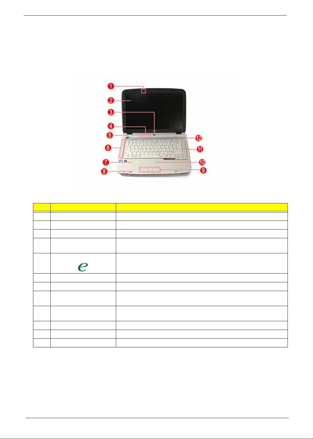
Front View
# Item Description
1 Acer PureZone Internal microphone for sound recording.
2 Display screen Also called Liquid-Crystal Display (LCD), displays computer output.
3 Power button Turns the computer on and off.
4 Status indicators Light-Emitting Diodes (LEDs) that light up to show the status of the
computer's functions and components.
5 Empowering key Launch Acer Empowering Technology.
6 Easy-launch buttons Buttons for launching frequently used programs.
7 Palmrest Comfortable support area for your hands when you use the computer.
8 Status indicators Light-Emitting Diodes (LEDs) that light up to show the status of the
computer's functions and components.
9 Click buttons (left, center
and right)
10 Touchpad Touch-sensitive pointing device which functions like a computer mouse.
11 Keyboard For entering data into your computer.
12 Speakers Left and right speakers deliver stereo audio output.
The left and right buttons function like the left and right mouse buttons;
the center button serves as a 4-way scroll button.
4 Chapter 1
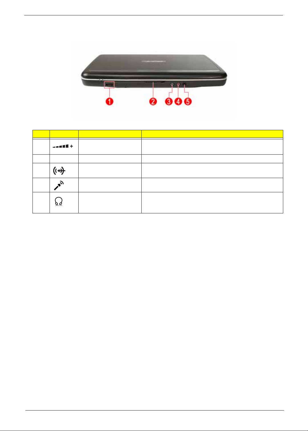
Closed Front View
# Icon Item Description
1 Unlimited volume control
wheel
2 Latch Locks and releases the lid.
3 Line-in jack Accepts audio line-in devices (e.g., audio CD player, stereo
4 Microphone jack Accepts inputs from external microphones.
Adjust the volume of the audio-out.
walkman, mp3 player)
5 Headphones/speaker/
line-out jack with
S/PDIF support
Connects to audio line-out devices
(e.g., speakers, headphones).
Chapter 1 5
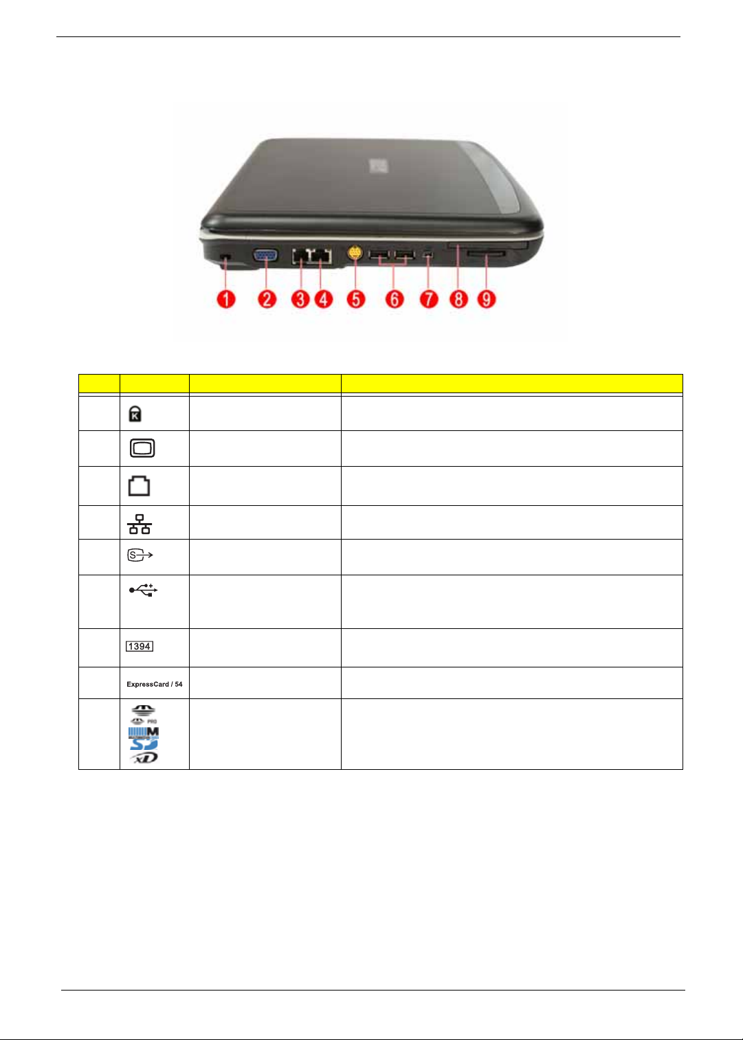
Left View
# Icon Item Description
1 Kensington lock slot Connects to a Kensington-compatible computer security
lock.
2 External display (VGA)
port
3 Modem (RJ-11) port Connects to a phone line.
Connects to a display device
(e.g., external monitor, LCD projector).
4 Ethernet (RJ-45) port Connects to an Ethernet 10/100/1000-based network.
5 S-video/TV-out (NTSC/
PAL) port
6 2 USB 2.0 ports Connect to USB 2.0 devices (e.g., USB mouse, USB
7 4-pin IEEE 1394 port Connects to IEEE 1394 devices.
8 ExpressCard/54 slot Accepts one ExpressCard/54 module.
9 5-in-1 card reader Accepts Secure Digital (SD), MultiMediaCard (MMC),
Connects to a television or display device with S-video input.
camera).
Memory Stick (MS), Memory Stick Pro (MS PRO), and xDPicture Card.
Note: Only one card can operate at any given time.
6 Chapter 1
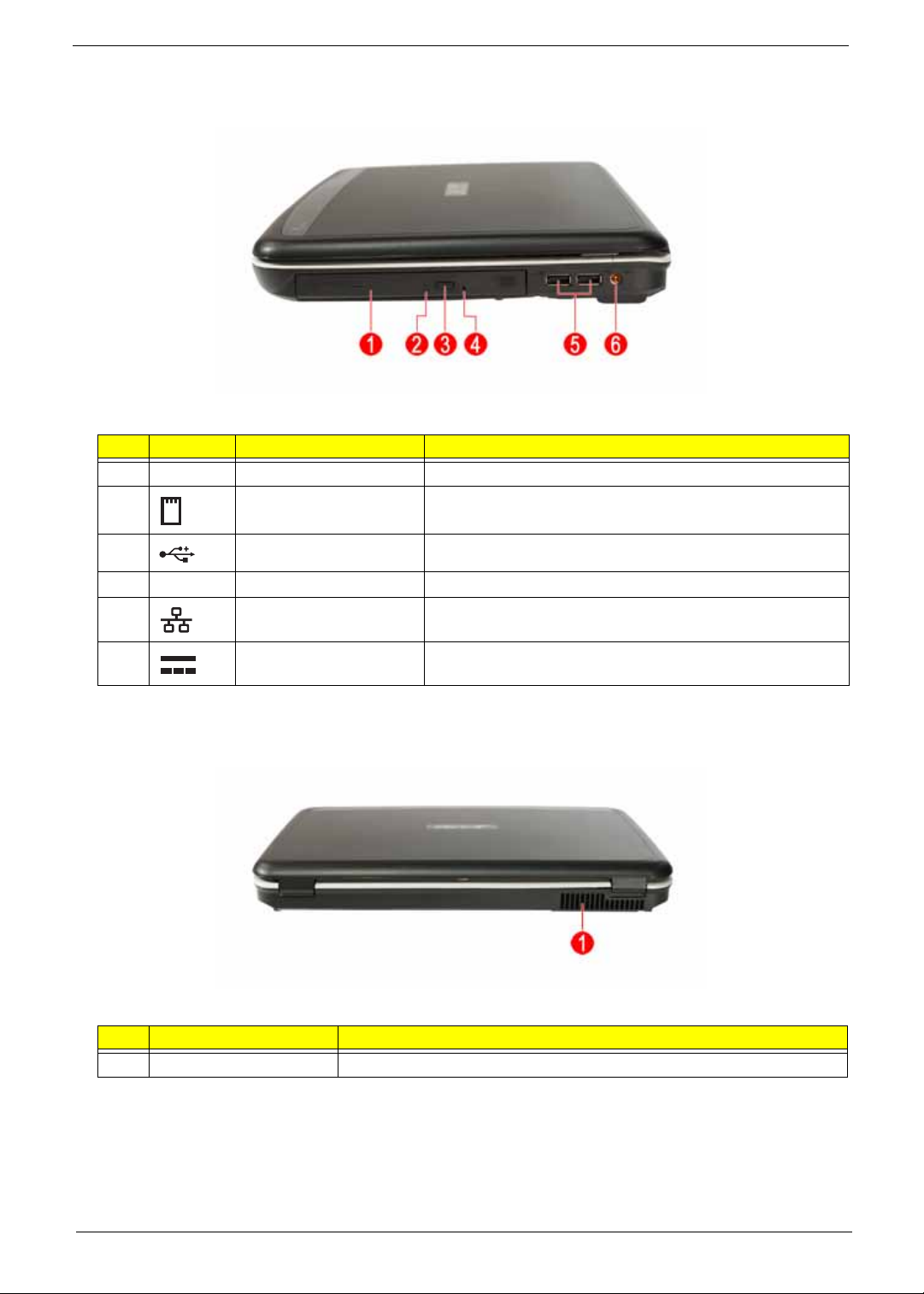
Right View
# Icon Item Description
1 Optical drive Internal optical drive; accepts CDs or DVDs.
2 Optical disk access
indicator
3 Optical drive eject button Ejects the optical disk from the drive.
Lights up when the optical drive is active.
4 Emergency eject hole Ejects the optical drive tray when the computer is turned off.
5 USB 2.0 ports Connect to USB 2.0 devices (e.g., USB mouse, USB
camera).
6 DC-in jack Connects to an AC adapter.
Rear Panel
# Item Description
1 Ventilation slots Enable the computer to stay cool, even after prolonged use.
Chapter 1 7
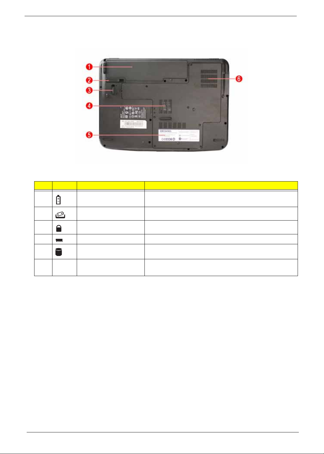
Bottom Panel
# Icon Item Description
1 Battery bay Houses the computer's battery pack.
2 Battery release latch Releases the battery for removal.
3 Battery lock Locks the battery in position.
4 Memory compartment Houses the computer's main memory.
5 Hard disk bay Houses the computer’s hard disk (secured with screws)
6 Ventilation slots and
cooling fan
Enable the computer to stay cool, even after prolonged use.
Note: Do not cover or obstruct the opening of the fan.
8 Chapter 1
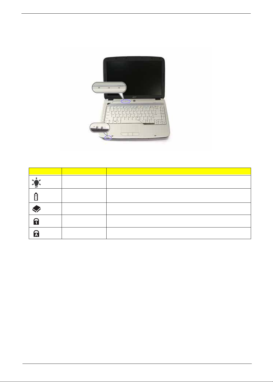
Indicators
The computer has four easy-to-read status indicators:
The front panel indicators are visible even when the computer cover is closed up.
Icon Function Description
Power Indicates the computer's power status.
Battery Indicates the computer's batttery status.
HDD Indicates when the hard disk drive is active.
Num lock Lights up when Num Lock is activated.
Caps lock Lights up when Caps Lock is activated.
NOTE: Battery LED status during charging:
• Amber: Charging.
• Green: Charging complete.
Chapter 1 9
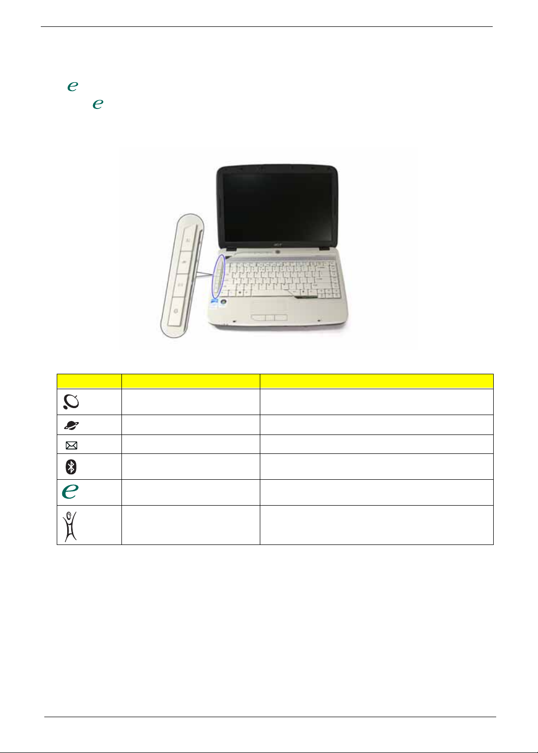
Easy-launch Buttons
There are several conveniently located easy-launch buttons. They are: mail, Web browser, Empowering Key
< > and one user-programmable button.
Press < > to run the Acer Empowering Technology . The mail and Web browser buttons are pre-set to email
and Internet programs, but can be reset by users. To set the Web browser, mail and programmable buttons,
run the Acer Launch Manager.
Icon Function Description
Wireless communication button/
indicator
Web browser Internet browser (user-Programmable)
Mail Email application (user-Programmable)
Bluetooth communication
button/indicator
Empowering Technology Launch Acer Empowering Technology.
Acer Arcade Launch Acer Arcade utility
Enables/disables the wireless function. Indicates the
status of wireless LAN communica ti o n.
Enables/disables the Bluetooth function. Indicates the
status of Bluetooth communication.
(user-programmable)
10 Chapter 1
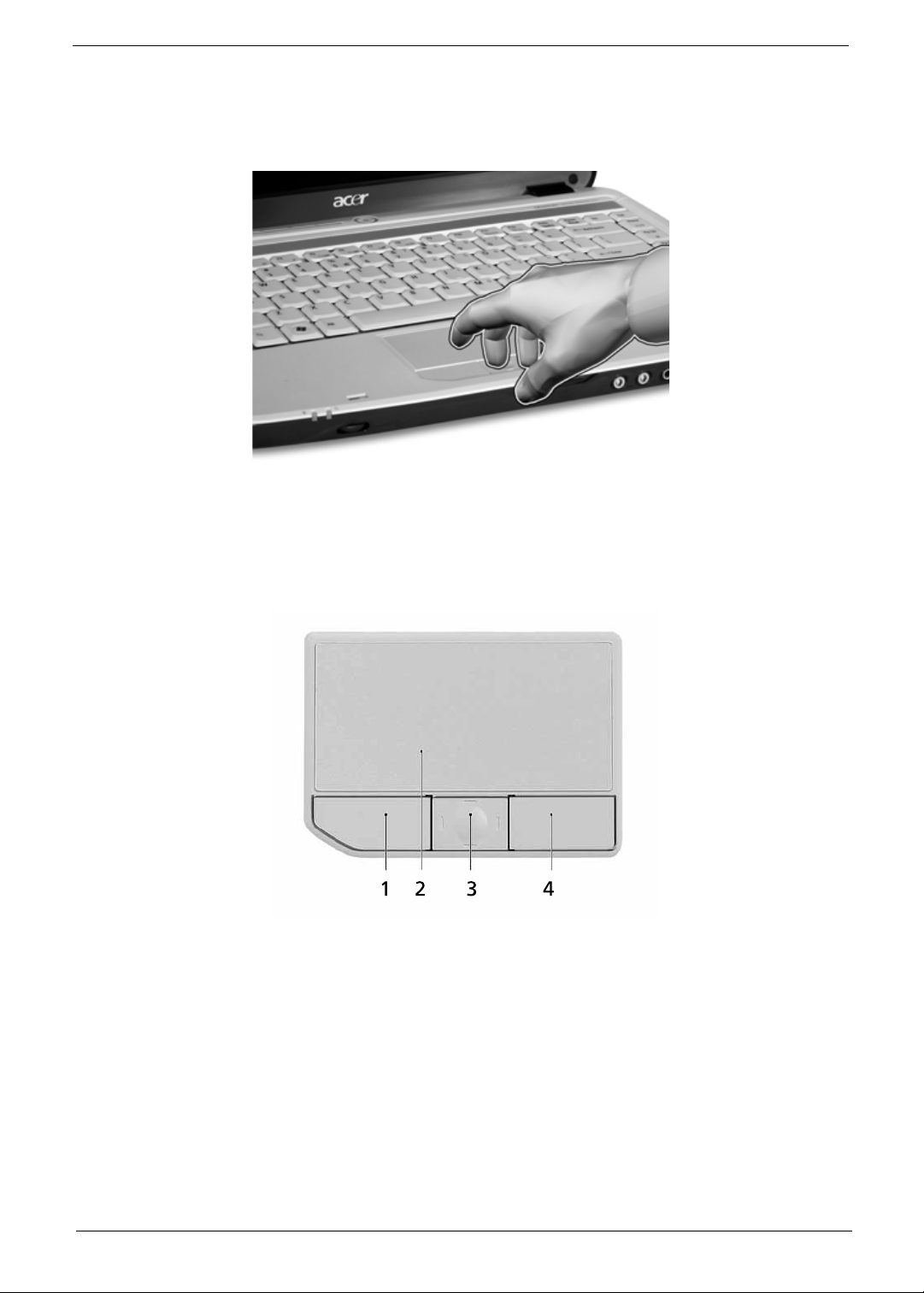
Touchpad
The built-in touchpad is a pointing device that senses movement on its surface. This means the cursor
responds as you move your finger across the surface of the touchpad. The central location on the palmrest
provides optimum comfort and support.
Touchpad Basics
The following teaches you how to use the touchpad:
T Move your finger across the touchpad (2) to move the cursor.
T Press the left (1) and right (4) buttons located beneath the touchpad to perform selection and execution
functions. These two buttons are similar to the left and right buttons on a mouse. Tapping on the
touchpad is the same as clicking the left button.
T Use the 4-way scroll (3) button (for selected models) or Acer BioProtect fingerprint reader (3) supporting
Acer FingerNav 4-way control function (for selected models) to scroll up or down and move left or right a
page. This button or fingerprint reader mimics your cursor pressing on the right scroll bar of Windows
applications.
Chapter 1 11
Function Left Button (1)
Execute Click twice
quickly.
Select Click once. Tap once.
Drag Click and hold,
then use finger to
drag the cursor
on the touchpad
Access context
menu
Scroll Click and hold to
NOTE: When using the touchpad, keep it - and your fingers - dry and clean. The touchpad is sensitive to finger
movement; hence, the lighter the touch, the better the response. Tapping too hard will not increase the
touchpad’s responsiveness.
NOTE: By default, vertical and horizontal scrolling is enabled on your touchpad. It can be disabled under
Mouse settings in Windows Control Panel.
Right Button
(4)
Click once
Main touchpad (2) Center button (3)
Tap twice (at the same
speed as double-clicking
the mouse button).
Tap twice (at the same
speed as double-clicking
a mouse button) then
hold finger to the
touchpad on the second
tap to drag the cursor.
move up/down/left/
right.
12 Chapter 1
Using the Keyboard
The keyboard has full-sized keys and an embedded keypad, separate cursor keys, two Windows keys and
twelve function keys, and two special keys.
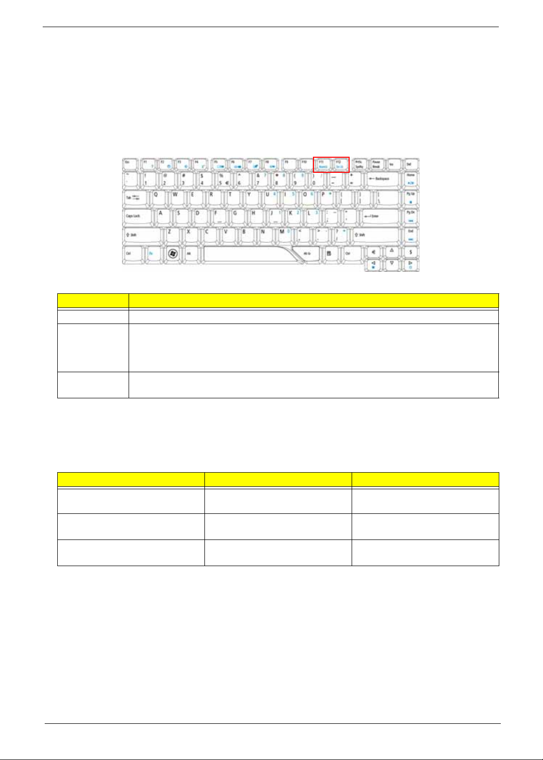
Lock Keys and Embedded Numeric Keypad
The keyboard has three lock keys which you can toggle on and off.
Lock Key Description
Caps Lock When Caps Lock is on, all alphabetic characters typed are in uppercase.
Num Lock
<Fn> + <F11>
Scroll Lock
<Fn> + <F12>
When Num Lock is on, the embedded keypad is in numeric mode. The keys function as a
calculator (complete with the arithmetic operators +, -, *, and /). Use this mode when you
need to do a lot of numeric data entry. A better solution would be to connect an external
keypad.
When Scroll Lock is on, the screen moves one line up or down when you press the up or
down arrow keys respectively. Scroll Lock does not work with some applications.
The embedded numeric keypad functions like a desktop numeric keypad. It is indicated by small characters
located on the upper right corner of the keycaps. To simplify the keyboard legend, cursor-control key symbols
are not printed on the keys.
Desired Access Num Lock On Num Lock Off
Number keys on embedded
keypad.
Cursor-control keys on embedded
keypad
Main keyboard keys Hold <Fn> while typing letters on
Type numbers in a normal
manner.
Hold <Shift> while using cursorcontrol keys.
embedded keypad.
N/A
Hold <Fn> while using cursorcontrol keys.
Type the lett ers i n a norma l
manner.
Chapter 1 13
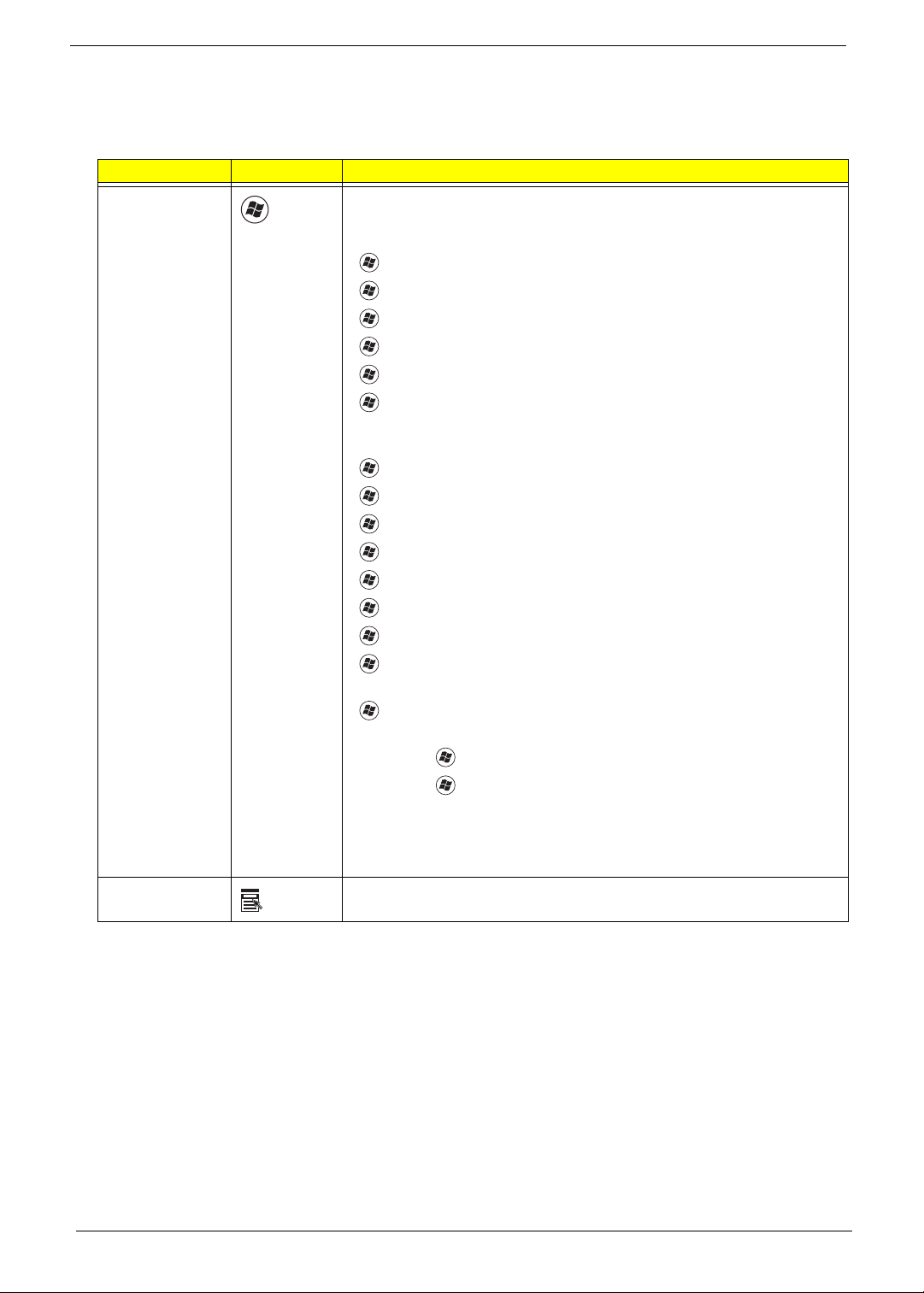
Windows Keys
The keyboard has two keys that perform Windows-specific functions.
Key Icon Description
Windows key Pressed alone, this key has the same effect as clicking on the Windows
Start button; it launches the Start menu.
It can also be used with other keys to provide a variety of functions:
< > : Open or close the Start menu
< > + <D>: Display the desktop
< > + <E>: Open Windows Explore
<> + <F>: Search for a file or folder
<> + <G>: Cycle through Sidebar gadgets
<> + <L>: Lock your computer (if you are connected to a network
domain), or switch users (if you're not connected to a
network domain)
<> + <M>: Minimizes all windows
< > + <R>: Open the Run dialog box
<> + <T>: Cycle through programs on the taskbar
< > + <U>: Open Ease of Access Center
<> + <X>: Open Windows Mobility Center
<> + <BREAK>: Display the System Properties dialog box
< > + <SHIFT+M>: Restore minimized windows to the desktop
< > + <TAB>: Cycle through programs on the taskbar by using
Windows Flip 3-D
< > + <SPACEBAR>: Bring all gadgets to the front and select
Windows Sidebar
<CTRL> + < > + <F>: Search for computers (if you are on a network)
<CTRL> + < > + <TAB>: Use the arrow keys to cycle through
programs on the taskbar by using Windows
Flip 3-D
Note: Depending on your edition of Windows Vista, some shortcuts may
not function as described.
Application key This key has the same effect as clicking the right mouse button; it opens
the application's context menu.
14 Chapter 1
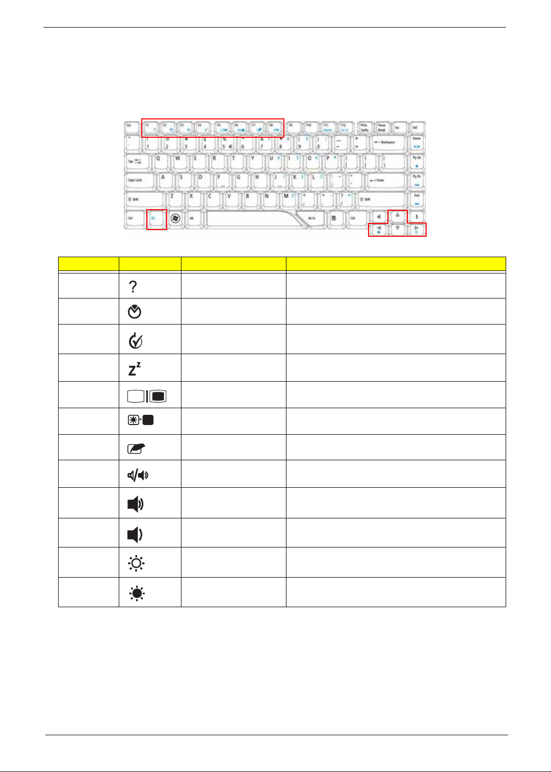
Hotkeys
The computer employs hotkeys or key combinations to access most of the computer's controls like screen
brightness, volume output and the BIOS utility.
To activate hotkeys, press and hold the <Fn> key before pressing the other key in the hotkey combination.
Hot Key Icon Function Description
Fn-F1 Hot key help Displays help on hot keys.
Fn-F2 Acer eSettings Launches the Acer eSettings in Acer eManager.
Fn-F3 Acer ePower
Management
Fn-F4 Sleep Puts the computer in Sleep mode.
Fn-F5 Display toggle Switches display output between the display screen,
Fn-F6 Screen blank Turns the display screen backlight off to save power.
Fn-F7 Touchpad toggle Turns the internal touchpad on and off.
Fn-F8 Speaker toggle Turns the speakers on and off.
Fn-w Volume up Increases the speaker volume.
Fn-y Volume down Decreases the speaker volume.
Fn-x Brightness up Increases the screen brightness.
Fn-z Brightness down Decreases the screen brightness
Launches the Acer ePowerManagement in Acer
eManager.
external monitor (if connected) and both.
Press any key to return.
Chapter 1 15
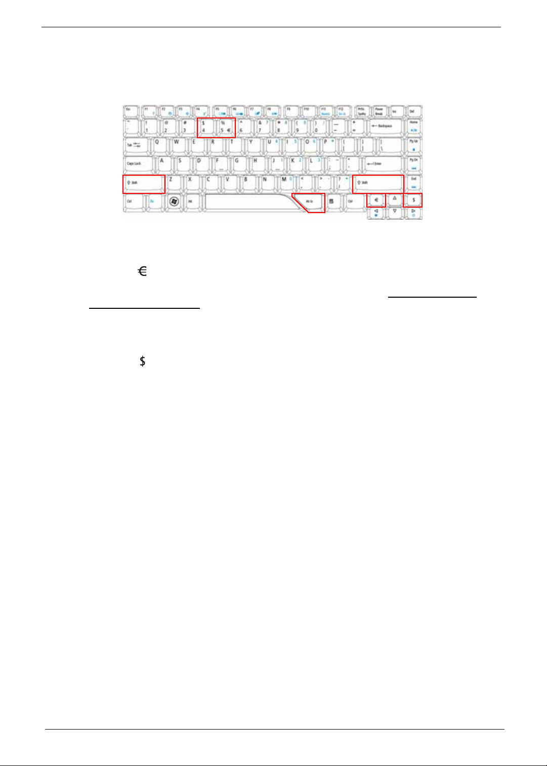
Special Keys
You can locate the Euro symbol and the US dollar sign at the upper-center and/or bottom-right of your
keyboard.
The Euro symbol
1. Open a text editor or word processor.
2. Either press < > at the bottom-right of the keyboard, or hold <Alt Gr> and then press the <5> key at the
upper-center of the keyboard.
NOTE: Some fonts and software do not support the Euro symbol. Please refer to www.microsoft.com/
typography/faq/faq12.htm for more information.
The US dollar sign
1. Open a text editor or word processor.
2. Either press < > at the bottom-right of the keyboard, or hold <Shift> and then press the <4> key at the
upper-center of the keyboard.
NOTE: This function varies according to the language settings.
16 Chapter 1

Acer Empowering Technology
The Empowering Technology toolbar makes it easy for you to access frequently used functions and manage
your new Acer system. Displayed by default in the upper half of your screen, it provides access to the following
utilities:
T Acer eNet Management hooks up to location-based networks intelligently.
T Acer ePower Management optimizes battery usage via customizable power plans.
T Acer ePresentation Management connects to a projector and adjusts display settings.
T Acer eDataSecurity Management protects data with passwords and encryption.
T Acer eLock Management limits access to external storage media.
T Acer eRecovery Management backs up and recovers data flexibly, reliably
and completely.
T Acer eSettings Management accesses system information and adjusts settings easily.
For more information, right click on the Empowering Technology toolbar, then select the "Help" or "Tutorial"
function.
Empowering Technology Password
Before using Acer eLock Management and Acer eRecovery Management, you must initialize the Empowering
Technology password. Right-click on the Empowering Technology toolbar and select "Password Setup" to do
so. If you have not initialized the Empowering Technology password and run Acer eLock Management or Acer
eRecovery Management, you will be asked to create it.
NOTE: If you lose the Empowering Technology password, there is no way to reset it except by reformatting
your system. Make sure to remember or write down your password!
Chapter 1 17

Acer eNet Management
Acer eNet Management helps you quickly connect to both wired and wireless networks in a variety of
locations. To access this utility, select "Acer eNet Management" from the Empowering Technology toolbar or
run the program from the Acer Empowering Technology program group in Start menu. You can also set Acer
eNet Management to start automatically when you boot up your PC.
Acer eNet Management automatically detects the best settings for a new location, while offering you the option
to manually adjust the settings to match your needs.
18 Chapter 1
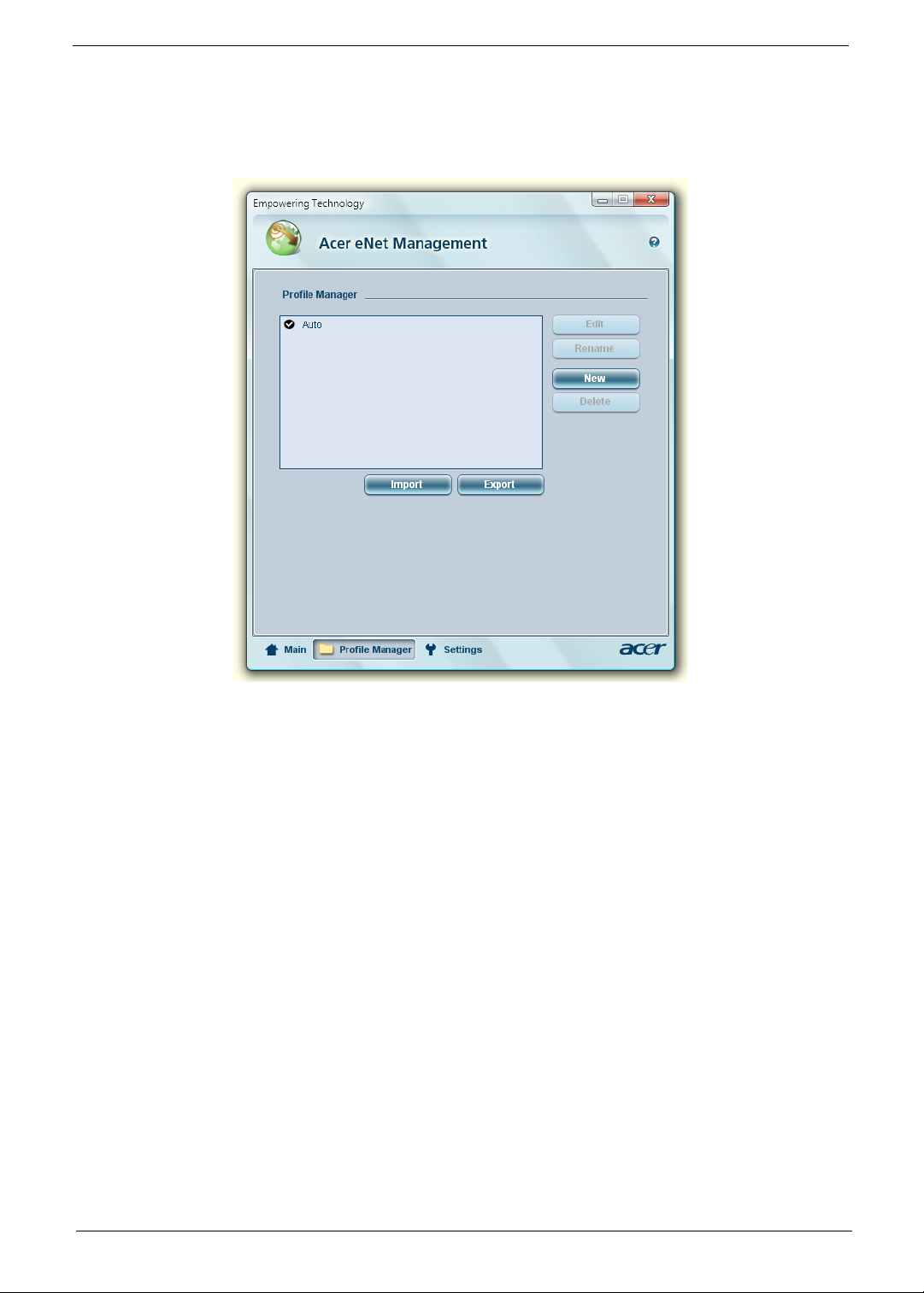
Acer eNet Management can save network settings for a location to a profile, and automatically switch to the
appropriate profile when you move from one location to another. Settings stored include network connection
settings (IP and DNS settings, wireless AP details, etc.), as well as default printer settings. Security and safety
concerns mean that Acer eNet Management does not store username and password information.
Chapter 1 19

Acer ePower Management
Acer ePower Management features a straightforward user interface for configuring your power management
options. To access this utility, select "Acer ePower Management" from the Empowering Technology toolbar,
run the program from the Acer Empowering Technology program group in Start menu, or right-click the
Windows power icon in the system tray and select "Acer ePower Management".
Using Power Plans
Acer ePower Management comes with three predefined power plans: Balanced, High performance and Power
saver. You can also create customized power plans. You can create, switch between, edit, delete and restore
power plans, as described below.
View and adjust settings for On Battery and Plugged In modes by clicking the appropriate tabs. You can open
Windows power options by clicking "More Power Options".
NOTE: You cannot delete the predefined power plans.
To create a new power plan:
Creating customized power plans allows you to save and quickly switch to a personalized set of power
options.
1. Click the Create Power Plan icon.
2. Enter a name for your new power plan.
3. Choose a predefined power plan to base your customized plan on.
4. If necessary, change the display and sleep settings you want your computer to use.
5. Click "OK" to save your new power plan.
To switch between power plans:
1. Select the power plan you wish to switch to from the drop-down list.
2. Click "Apply".
To edit a power plan:
Editing a power plan allows you to adjust system settings like LCD brightness and CPU speed. You can also
turn on/off system components to extend battery life.
1. Switch to the power plan you wish to edit
2. Adjust settings as required.
3. Click "Apply" to save your new settings.
To delete a power plan:
Y ou cannot delete the power plan you are currently using. If you want to delete the active power plan, switch to
another one first.
1. Select the power plan you wish to delete from the drop-down list.
2. Click the Delete Power Plan icon.
20 Chapter 1

Battery status
For real-time battery life estimates based on current usage, refer to the panel in the upper half of the window.
Click the to view estimated battery life in sleep and hibernate modes.
Chapter 1 21

Acer eAudio Management
Acer eAudio Management allows you to easily control the enhanced sound effects of Dolby® Home Theater™
on your system. Select "Movie" or "Game" mode to experience the awesome realism of 5.1-channel surround
sound from just 2 speakers, via Dolby Virtual Speaker technology. "Music" mode lets you enjoy your favorite
tunes, in vivid detail.
22 Chapter 1

Acer ePresentation Management
Acer ePresentation Management lets you project your computer's display to an external display device or
projector using the hotkey: <Fn> + <F5>. If auto-detection hardware is implemented in the system and the
external display supports it, your system display will be automatically switched out when an external display is
connected to the system. For projectors and external devices that are not auto-detected, launch Acer
ePresentation Management to choose an appropriate display setting.
NOTE: If the restored resolution is not correct after disconnecting a projector, or you need to use an external
resolution that is not supported by Acer ePresentation Management, adjust your display settings using
Display Properties or the utility provided by the graphics vendor.
Chapter 1 23

Acer eDataSecurity Management
Acer eDataSecurity Management is an encryption utility that protects your files from being accessed by
unauthorized persons. It is conveniently integrated with Windows Explorer as a shell extension for quick data
encryption/decryption and also supports on-the-fly file encryption for Lotus Notes and Micro s oft Outlook.
The Acer eDataSecurity Management setup wizard will prompt you for a supervisor password and default
encryption password. This password will be used to encrypt files by default, or you can choose to enter your
own password when encrypting a file.
NOTE: The password used to encrypt a file is the unique key that the system needs to decrypt it. If you lose
the password, the supervisor password is the only other key capable of decrypting the file. If you lose
both passwords, there will be no way to decrypt your encrypted file! Be sure to safeguard all related
passwords!
24 Chapter 1

Acer eLock Management
Acer eLock Management is simple yet effective utility that allows you to lock removable storage, optical and
floppy drive devices to ensure that data can't be stolen while your system is unattended.
T Removable Storage Devices — includes USB disk drives, USB pen drives, USB flash drives, USB MP3
drives, USB memory card readers, IEEE 1394 disk drives, and any other removable storage devices
that can be mounted as a file system when plugged into the system.
T Optical Drive Devices — includes any kind of CD-ROM, DVD-ROM, HD-DVD or Blu-ray drive devices.
T Floppy Drive Devices — 3.5-inch floppy drives only.
To use Acer eLock Management, the Empowering Technology password must be set first. Once set, you can
apply locks to any of the devices types. Lock(s) will immediately be set without any reboot necessary, and will
remain after rebooting, until removed.
NOTE: If you lose the Empowering T echnology password, there is no method to reset it except by reformatting
your system. Make sure to remember or write down your password.
Chapter 1 25

Acer eRecovery Management
Acer eRecovery Management is a versatile backup utility. It allows you to create full or incremental backups,
burn the factory default image to optical disc, and restore from previously created backups or reinstall
applications and drivers. By default, user-created backups are stored to the D:\ drive.
Acer eRecovery Management provides you with:
T Password protection (Empowering Technology password)
T Full and incremental backups to hard disk or optical disc
T Creation of backups:
t Factory default image
t User backup image
t Current system configuration
t Application backup
T Restore and recovery:
t Factory default image
t User backup image
t From previously-created CD/DVD
t Reinstall applications/drivers
NOTE: If your computer did not come with a Recovery CD or System CD, please use Acer eRecovery
Management's "System backup to optical disc" feature to burn a backup image to CD or DVD. To
ensure the best results when recovering your system using a CD or Acer eRecovery Management,
detach all peripherals (except the external Acer ODD, if your computer has one), including your Acer
ezDock.
26 Chapter 1

Acer eSettings Management
Acer eSettings Management allows you to inspect hardware specifications, set BIOS passwords and modify
boot options.
Acer eSettings Management also:
T Provides a simple graphical user interface for navigation.
T Prints and saves hardware specifications.
T Lets you set an asset tag for your system.
Chapter 1 27

Windows Mobility Center
The Windows Mobility Center collects key mobile-related system settings in one easy-to-find place, so you can
quickly configure your Acer system to fit the situation as you change locations, networks or activities. Settings
include display brightness, power plan, volume, wireless networking on/off, external display settings, display
orientation and synchronization status.
Windows Mobility Center also includes Acer-specific settings like Bluetooth Add Device (if applicable), sharing
folders overview/sharing service on or off, and a shortcut to the Acer user guide, drivers and utilities.
To launch Windows Mobility Center:
T Use the shortcut key < > + <X>
T Start Windows Mobility Center from the Control panel
T Start Windows Mobility Center from the Accessories program group in the Start menu
28 Chapter 1

Using the System Utilities
Acer GridVista (dual-display compatible)
To enable the dual display feature of your notebook, first ensure that a second display is connected, then,
open the Display Settings properties box using the Control Panel or by right-clicking the Windows desktop
and selecting Personalize. Select the secondary monitor (2) icon in the display box and then click the check
box Extend the desktop onto this monitor. Finally, click Apply to confirm the new settings and click OK to
complete the process.
Acer GridVista is a handy utility that offers four pre-defined display settings so you can view multiple windows
on the same screen. To access this function, please go to Start, All Programs and click on Acer GridVista.
You may choose any one of the four display settings indicated below:
12
Double (vertical), Triple (primary at left), Triple (primary at right), or Quad
Acer Gridvista is dual-display compatible, allowing two displays to be partitioned independently.
Acer GridVista is simple to set up:
1. Run Acer GridVista and select your preferred screen configuration for each display from the taskbar.
2. Drag and drop each window into the appropriate grid.
3. Enjoy the convenience of a well-organized desktop.
1
3
2
1
3
2
3
1
4
2
Chapter 1 29

NOTE: Please ensure that the resolution setting of your second monitor is set to the manufacturer's
recommended value.
Launch Manager
Launch Manager allows you to set the four easy-launch buttons located above the keyboard.
You can access the Launch Manager by clicking on Start, All Programs, and then Launch Manager to start
the application.
30 Chapter 1

Norton Internet Security
Norton Internet Security is an anti-virus utility that can protect against viruses, keeping your data safe and
secure.
How do I check for viruses?
1. Double-click the Norton Internet Security icon on the Windows desktop.
2. Select Tasks & Scans.
3. Select Run Scan to scan your system.
4. When the scan is complete, review the results of the scan.
NOTE: For optimal security, run a Full System Scan when scanning your computer for the first time.
You can schedule customized virus scans that run unattended on specific dates and times or at periodic
intervals. If you are using the computer when the scheduled scan begins, it runs in the background so that you
do not have to stop working.
For more information refer to the Norton Internet Security help files.
Chapter 1 31

Hardware Specifications and Configurations
Processor
Item Specification
CPU type Intel
Core 2
Duo
T7200
Mobile
Proces
sor
Clock
Speeds
L2 Cache 4 MB 4 MB 4 MB 2 MB 2 MB 2 MB 1 MB 1 MB 1 MB 1 MB
Front Side
Bus
System Board Major Chips
Item Specification
System core logic Intel 945PM Express + Intel ICH7M chipsets
HDD controller Intel ICH7M chipset
Memory controller Intel 945PM Express chipset
Video controller Intel 945PM Express chipset
Audio controller Codec ALC268
PCMCIA controller OZ129
LAN controller Intel ICH7M + Broadcom 5787MKMLG chipsets
Modem controller Intel ICH7M chipset
Bluetooth controller Intel ICH7M chipset
Keyboard controller Winbond WPC8768L
2 GHz 2.16
667
MHz
Intel
Core 2
Duo
T7400
Mobile
Proces
sor
GHz
667
MHz
Intel
Core
Duo
T7600
Mobile
Proces
sor
2.33
GHz
667
MHz
2
Intel
Core 2
Duo
T5300
Mobile
Proces
sor
1.73
GHz
533
MHz
Intel
Core
Duo
T5500
Mobile
Proces
sor
1.66
GHz
667
MHz
2
Intel
Core 2
Duo
T5600
Mobile
Proces
sor
1.83
GHz
667
MHz
Intel
Core 2
Duo
T2080
Mobile
Proces
sor
1.73
GHz
533
MHz
Intel
Celero
n M
440
Mobile
Proces
sor
1.86
GHz
533
MHz
Intel
Celero
n M
520
Mobile
Proces
sor
1.6
GHz
533
MHz
Intel
Celero
n M
530
Mobile
Proces
sor
1.73
GHz
533
MHz
Hard Disk Drive Interface
Item Specification
Product Hitachi Travelstar
5K160
Model Name HTS
Capacity (GB) 80 120 160 80 120 160 80 120 160 80 120 160
Form factor and
Interface type
Bytes per sector 512 512 N/A 512
Data heads 4 4 N/A 3
Data disks 2 2 N/A 2
Spindle speed
(RPM)
32 Chapter 1
HTS
HTS
5416
5416
5416
80J9
12J9
16J9
SA0
SA0
SA0
0
0
0
2.5 inch Serial ATA
5400 5400 5400 5400
Toshiba Western Digital Seagate
MK8
037
GSX
MK1
237
GSX
MK1
637
GSX
WD8
00B
EVS
WD1
200B
EVS
WD1
600B
EVS
ST9
8081
1AS
ST9
1208
22A
S
ST9
1608
21A
S

Hard Disk Drive Interface
Item Specification
Buffer size (MB) 8 8.192 8 8
Media transfer
540 300 600 N/A
rate (Mbytes/s,
max)
Interface transfer
150 MB/s N/A 150 MB/s 150 MB/s
rate (Mbytes/s,
max)
Voltage
5V(DC) +/- 5% 5V(DC) +/- 5% 5V(DC) +/- 5% 5V(DC) +/- 5%
tolerance
BIOS
Item Specification
BIOS vendor Phoenix
BIOS Version v0.25
Supported protocols ACPI 1.0b/2.0/3.0 compliance, PCI 2.2, System/HDD Password
Security Control, INT 13h Extenstions, PnP BIOS 1.0a, SMBIOS 2.4,
BIOS Boot Specification, Simple Boot Flag 1.0, Boot Block, PCI Bus
Power Management Interface Specification, USB Specification 1.1/2.0,
IEEE 1394 1.0, USB/1394 CD-ROM Boot Up support, PC Card
Standard 1995 (PCMCIA 3.0 Compliant Device), IrDA 1.0, HD audio,
WfM 2.0, Preboot Execution Environment 2.1, Boot Integrity Service
Application Program Interface (BIS) 1.0, PC2002/2005 compliant, Intel
Enhanced SpeedStep Technology, Intel DPST support, ASF 2.0, TPM
v1.2, AHCI support, iAMT 2.5
System Memory
Item Specification
Memory controller Intel 945PM Express chipset
DIMM socket number 2 sockets
Supports maximum
2 GB for 32 bit OS, 4 GB for 64bit OS
memory size
Vendor Samsung Hynix Nanya Powerchip Promos
Model name M470T2953
EZ3-CE6
HYMP512S
64CP8-Y5
NT512T64U
H8B0FN-3C
AS6E8E63B-6E1A V916764B24
QBFW-F5
DIMM type DDR2 Synchronous DRAM
DIMM speed (MHz) 667
DIMM size 1GB 1GB 512 MB 512 MB 512 MB
Video
Item Specification
VGA controller Intel 945PM Express chipset with integrated 3D graphics
Features AT I Mobility Radeon HD2300 with up to 896 MB of HyperMemory (128
MB of dedicated GDDR2 VRAM, up to 760 MB of shared system
memory) supporting Microsoft DirectX 9 and PCI Express
Chapter 1 33

Audio
Item Specification
Audio controller Realtek ALC268 Codec
Features Two built-in stereo speakers, Supports high definition audio, Built-in
microphone, MS-sound compatible
PCMCIA Port
Item Specification
PCMCIA controller TI7412
Card type support Type-II
Number of slot One
LAN
Item Specification
LAN controller Intel ICH7M + Broadcom 5785KMLG chipsets
LAN connector type RJ45
Features Onboard Gigabit Ethernet, PCI-E interface, support ASF 2.0
Wireless LAN module
Item Specification
Vendor Intel Foxconn
Model name Wireless WiFi
Link 4965AGN
Data throughput 54 Mbps
Protocol 802.11a/b/g 802.11 a/b/g 802.11 b/g 802.11 b/g
Interface PCI bus (mini PCI socket for wireless module)
Modem
Item Specification
Modem controller Intel 945PM Express chipset
Vendor Liteon Foxconn
Model name MDC-003#A8B MDC 1.5 T60M955.00
Baud rate 56 K
Modem connector type RJ11
Bluetooth Module
Item Specification
Bluetooth controller Intel ICH7M chipset
Vendor Foxconn BCM2045
Model name T60H928.01
Protocol Bluetooth 2.0
Connector type Mini USB
PRO/Wireless
3945ABG
PRO/Wireless
3945BG
Broadcom 4311
34 Chapter 1

Keyboard and Input Devices
Item Specification
Keyboard controller Winbond WPC8768L
Model name Acer FineTouch keyboard
Features 5-degree curve, 88-/89- key, inverted “T” cursor layout, 2.5 mm (minimum) key
travel, touchpad pointing device with 4-way scroll button or Acer BioProtect
fingerprint reader supporting Acer Finger Nav 4-way control function, hotkey
controls, embedded numeric keypad, multi-language support, three easy-
launch buttons, three productivity keys, and two front-access communication
switches
Combo Drive Interface
Item Specification
Vendor Sony Philips BenQ
Model name Slim Combo CRX880A DS-24CZP
Drive type Internal Slim CD-RW/DVD combo drive
Data transfer rate Write:
• CD-R: 24X
• CD-R W: 24X
Buffer Memory 2 MB N/A
Interface IDE
Applicable disc format CD-R, CD-RW (Multi speed, High speed, Ultra-speed and Ultra-speed plus)
CD-DA, CD-ROM (mode 1), CD-ROM XA (Mode 2, Form 1, Form 2), CD-I,
CD-i Bridge, Video-CD, Karaoke CD, Photo CD, Enhanced CD, CD Plus,
CD Extra, i-trax CD, CD-Text DVD-ROM, DVD-Video, DVD-Audio, SACD
(Hybrid), UDF DVD, DVD-R/RW, DVD+R/RW, DVD+/-R DL, DVD-RAM
V1.0/V2.1
Power supply 5 V DC
Read:
•DVD-ROM: 8X
• CD-ROM: 24X
Chapter 1 35

DVD Drive Interface
Item Specification
Vendor Sony Pioneer Philips BenQ Panasonic
Model name AD-7560A DVR-K17RS DS-8A1P UJ-850
Drive type Internal Slim DVD/CD writer
Data transfer rate Write:
•CD-R: 24X
CAV
•CD-RW: 24X
CAV
•DVD+RW/RW (single
layer): 8X, 6X
ZCLV
•DVD-R/+R
(single layer):
8X CAV
•DVD-R/+R
(double layer):
4X ZCLV
• DVD-RAM: 5X
ZCLV
Write:
• CD-R: 24X
•CD-RW: 24X
•DVD-RW: 6X
•DVD-R/+R/
+RW: 8X
Read:
•DVD-RAM: 5X
N/A Write:
• CD-R: 24X
•CD-RW: 16X
•DVD-R: 8X
•DVD-RW: 4X
•DVD-RAM: 5X
•DVD+R(DL):
2.4X
•DVD+R: 8X
•DVD+RW: 4X
Read:
• CD-R/RW/
ROM: 24X
•DVD-R/RW/
ROM: 8X
Read:
•CD-R/RW/
ROM: 24X
Max
•DVD-ROM
(single layer):
8X CAV
•DVD-ROM
(double layer):
6X CAV
• DVD-RAM: 5X
ZCLV
•DVD-R/+R/
+RW/-RW
(single layer):
8X CAV
•DVD-R/+R
(double layer):
6X CAV
Buffer Memory 2 MB
Interface Enhanced IDE(ATAPI) compatible
Applicable disc format DVD -RAM, DVD-R/RW, DVD+R (SL, DL)/RW, CD-R/RW, DVD-ROM, DVD-
RAM, DVD-R, DVD-RW, DVD+R (SL, DL), DVD+RW; CD-R, CD-RW, CDROM, CD-ROM XA, CD-DA, CD-I, CD-Extra, CD-Text, Photo CD, Video CD
Power supply 5V DC
36 Chapter 1

Battery
Item Specification
Vendor Panasonic Sanyo Sony Simplo
Battery Type Li-ion Li-ion Li-ion Li-ion
Pack capacity 6 cell:
2.0 mAh
6 cell:
2.4 mAh
6 cell:
2.0 mAh
6 cell:
2.4 mAh
6 cell:
2.0 mAh
6 cell:
2.4 mAh
6 cell:
2.0 mAh
6 cell:
2.4 mAh
LCD
Item Specification
Vendor AUO CMO LG Samsung
Model name B141EW04
(Non-glare)
B141EW04-
N141I3-L02
(Glare)
LP141WX1TLA1 (Nonglare)
LP141WX3TLB1(Glare)
LTN141W3L01-G (Glare)
V4 (Glare)
Screen diagonal (mm) 14.1” WXGA
Display resolution (pixels) 1280 x 800 1280 x 800 1280 x 768 N/A 1280 x 800
Aspect ratio 16:10 N/A 15:9 N/A N/A
Active area (mm) 303.36 x
N/A 305.8 x 183.2 N/A 303.4 x 189.6
189.6
Pixel pitch (mm) 0.237 N/A 0.2385 (107) N/A 0.237
Mode TN N/A N/A N/A N/A
Number of colors 262 K 262 K 262,144 (6
N/A 262 K
bit)
Color saturation (NTSC%) 45 N/A 45% N/A N/A
Typical white luminance (cd/
2
) also called brightness
m
200 220 185 (typ.5p) 200 200
Contrast ratio 400:1 300:1 500:1 N/A 500:1
Response time (optical rise
16 16 25 16 16
time + fall time) (msec)
Power consumption (watt) 5.1 5.3 N/A N/A N/A
Supply voltage (v) 3.3 N/A N/A N/A N/A
Backlight 1 CCFL N/A N/A N/A N/A
Outline dimensions (mm) 319.5 x 205.5
x 5.2
319.5 x 205
.5 x 5.2
320.0 x 199.0
x 5.5
N/A 319.5 x205.5
x 5.5
Weight (g) 400 400 400 N/A 390
LCD Inverter Board
Item Specification
Vendor YEC Foxconn RoHS
Model name YNV-W06S T621240.02 VK.21189.406
Chapter 1 37

AC Adapter
Item Specification
Vendor Delta Lite-On
Model Name ADP-90SB BBDAF PA-1900-24 AR
ADP-90SB BBEA LF PA-1900-04 WR
Output rating 19 V/4.74 A, 90 W 19 V , 90 W
Input (Vac) 90 ~ 270 100 ~ 240
System Power Management
ACPI mode Power Management
Off • Mech. Off (G3): All devices in the system are turned off
completely.
• Soft Of f (G2/S5): OS initiated shut down. All devices in the system
are turned off completely.
On • Working (G0/S0): Individual devices such as the CPU and hard
disc may be power managed in this state.
• Suspend to RAM (S3): CPU set power down, VGA Suspend,
PCMCIA Suspend, Audio Power Down, Hard Disk Power Down,
CD-ROM Power Down, and Super I/O Low Power mode.
• Save to Disk (S4): Also called Hibernation Mode. System saves
all system states and data onto the disc prior to system shutdown.
38 Chapter 1

Chapter 2
System Utilities
BIOS Setup Utility
The BIOS Setup Utility is a hardware configuration program built into your system’s BIOS (Basic Input/Output
System). Since most systems are already properly configured and optimized, there is no need to run this utility.
The BIOS setup utility stores basic settings for your system. You will need to run this utility if you encounter
configuration problems. Refer to Chapter 4 Troubleshooting when problem arises.
Entering BIOS Setup
Power on the system to start the system POST process. During bootup, press F2 to enter the BIOS setup
screen.
NOTE: You must press F2 while the system is booting. This key does not work during any other time.
BIOS Setup Primary Menus
There are several tabs on the setup screen corresponding to the six primiary BIOS menus.
T Information
T Main
T Security
T Boot
T Exit
In the descriptive table follow i n g ea ch of the screen illustrations, settings in boldface are the default and
suggested parameter settings.
BIOS Setup Navigation Keys
Note the following reminders when moving around the Setup utility.
T Use the Left and Right arrow keys to move to the next page or to return to the previous screen.
T Use the Up and Down arrow keys to select an item.
T Use the + and - keys to select an option.
NOTE: You can configure a parameter that is enclosed in square brackets. Grayed-out items have fixed
settings and are not user-configurable.
T Use the Enter key to display a submenu screen.
NOTE: When a parameter is preceeded by an arrow or (>), it means that a submenu screen is available.
T Press F1 for General Help using the BIOS setup.
T Press F9 to load the default configuration.
T Press F10 to save changes and close the BIOS setup.
T Press Esc to close the BIOSe setup.
NOTE: The parameters on the screens shown in this Guide display default system values. These values may
not be the same as those in the system. System information is subject to different models.
Chapter 2 39

Information Menu
Parameter Description
CPU Type Type of processor currently installed in the system.
CPU Speed Speed of the processor currently installed in the system.
IDE0 Model Name Model name of HDD installed on the primary IDE channel.
IDE0 Serial Number Serial number of HDD installed on the primary IDE channel.
ATAPI Model Name Model name of the ATAPI CD/DVD-ROM drive installed in the system.
System BIOS Version Version number of the BIOS setup utility.
VGA BIOS Version Version number of the VGA firmware.
KBC Version Version number of the keyboard controller.
Serial Number Serial number of the system.
Asset Tag Number Asset tag number of the system.
Product Name Product name of the system.
Manufacturer Name Name of the manufacturer of this system.
UUID Visible only when an internal LAN device is present.
UUID=32bytes
NOTE: The system configuration information varies in different models.
40 Chapter 2

Main Menu
Parameter Description Format/Option
System Time Set the system time following the hour-minute-second format. Format: HH:MM:SS
(hour:minute:second)
System Date Set the date following the weekday-month-day-year format. Format MM/DD/YYYY
(month/day/year)
System Memory Total size of system memory detected during POST.
Extended Memory Total size of extended memory during POST.
Video Memory Total size of VGA memory.
Quiet Boot When Enabled, the BIOS splash screen is displayed during
startup.
Network Boot When Enabled, the system can be booted from another PC on
your LAN, such as a remote server.
F12 Boot Menu When Enabled, pressing the F12 key during POST brings up a
menu of devices that you can select to boot.
D2D Recovery Enables or disables disk-to-disk recovery. D2D recovery is a
method of restoring the system to factory configurations without
using recovery CDs.
Enabled
Disabled
Enabled
Disabled
Disabled
Enabled
Enabled
Disabled
Chapter 2 41

Security Menu
Parameter Description Option
Supervisor Password Is Indicates whether a supervisor password has been
assigned.
User Password Is Indicates whether a user password has been
assigned.
HDD Password Is Indicates whether a hard disk drive password has
been assigned.
Set Supervisor Password Press Enter to configure the supervisor password.
Set User Password Press Enter to configure the user password.
Set HDD Password Press Enter to configure the hard disk drive
password.
Password on Boot Enables or disables security check during POST.
Clear or Set
Clear or Set
Clear or HDD Password Set
Disabled or Enabled
NOTE: Refer to the “Removing a System Password” section for more information on how to remove a
password.
42 Chapter 2

Setting a System Password
1. Use the up/down keys to select a password parameter (Set Supervisor Password, Set User Password, or
Set Secondary MAS.Disk Password), then press Enter. A Password box will appear.
2. Type a password then press Enter.
The password may consist of up to six alphanumeric characters (A-Z, a-z, 0-9).
3. Retype the password to verify the first entry then press Enter again.
4. Press F10.
5. Select Yes to save the new password and close the Setup Utility.
Changing a System Password
1. Use the up/down keys to select a password parameter (Set Supervisor Password, Set User Password, or
Set Secondary MAS.Disk Password), then press Enter.
2. Type the original password then press Enter.
3. Type a new password then press Enter.
4. Retype the password to verify the first entry then press Enter again.
5. Press F10.
6. Select Yes to save the new password and close the Setup Utility.
Removing a System Password
1. Use the up/down keys to select a password parameter (Set Supervisor Password, Set User Password, or
Set Secondary MAS.Disk Password), then press Enter.
2. Enter the current password then press Enter.
3. Press Enter twice without entering anything in the new and confirm password fields.
4. After doing this, the system automatically sets the related password parameter to Clear.
Chapter 2 43

Boot Menu
This menu allows you to set the drive priority during system boot-up. The system will attempt to boot from the
first device on the list. If the first device is not available, it will continue down the list until it reaches an available
device. BIOS setup will display an error message if the drive(s) specified is not bootable.
44 Chapter 2

Exit Menu
Parameter Description
Exit Saving Changes Save changes made and close the BIOS setup.
Exit Discarding Changes Discards changes made and close the BIOS setup.
Load Setup Defaults Loads the default settings for all BIOS setup parameters. Setup Defaults are quite
demanding in terms of resources consumption. If you are using low-speed memory chips or
other kinds of low-performance components and you choose to load these settings, the
system might not function properly.
Discard Changes Discards all changes made in the BIOS setup.
Save Changes Saves changes made in the BIOS setup.
Chapter 2 45

46 Chapter 2

Machine Disassembly and Replacement
This chapter contains step-by-step procedures on how to disassemble the notebook computer for
maintenance and troubleshooting.
Disassembly Requirements
To disassemble the computer, you need the following tools:
T Wrist grounding strap and conductive mat for preventing electrostatic discharge
T Flat screwdriver
T Philips screwdriver
T Hex screwdriver
T Plastic flat-blade screwdriver
T Plastic tweezers
NOTE: The screws for the different components vary in size. During the disassembly process, group the
screws with the corresponding components to avoid mismatch when putting back the components.
Chapter 3
Chapter 3 47

General Information
Pre-disassembly Instructions
Before proceeding with the disassembly procedure, make sure that you do the following:
1. Turn off the power to the system and all peripherals.
2. Unplug the AC adapter and all power and signal cables from the system.
3. Place the system on a flat, stable surface.
4. Remove the battery pack. See “Removing the Battery Pack” on page 51.
48 Chapter 3

Disassembly Process
The disassembly process is divided into the following stages:
T External module disassembly
T Main unit disassembly
T LCD module disassembly
The flowcharts provided in the succeeding disassembly sections illustrate the entire disassembly sequence.
Observe the order of the sequence to avoid damage to any of the hardware components. For example, if you
want to remove the mainboard, you must first remove the keyboard, then disassemble the inside assembly
frame in that order.
Main Screw List
Item Screw Color Part No.
A M2 x L4 (torque 1.6) Black 86.00F24.724
M2 x L4 (torque 3.0)
B M3 x L4 Silver 86.9A554.4R0
C M2 x L6 Black 86.00F58.726
D M2 x L2.5 Silver 86.00F22.722
E M2 x L4 86.9A552.3R0
F M2.5 x L8 Black 86.00E34.738
G M2.5 x L6 86.00E33.736
H M2 x L3 Silver 86.00C07.220
I M2 x L2.5 Silver 86.9A552.6R0
Chapter 3 49

External Module Disassembly Process
External Modules Disassembly Flowchart
The flowchart below gives you a graphic representation on the entire disassembly sequence and instructs you
on the components that need to be removed during servicing. For example, if you want to remove the
mainboard, you must first remove the keyboard, then disassemble the inside assembly frame in that order.
EXTERNAL MODULE DISASSEMBLY
TURN OFF POWER
AND PERIPHERALS
UNPLUG POWER
CABLES
Ax8
LOWER
COVER
Ax2
WLAN
BOARD
Screw List
Item Screw Part No.
A M2 x L4 86.00F24.724
B M3 x L4 86.9A554.4R0
C M2 x L6 86.00F58.726
D M2 x L2.5 86.00F22.722
DIMM
MODULES
Ax2
HARD DISK
BRACKET
Ax1
HARD DISK
DRIVE
DRIVE
MODULE
HDD
MODULE
HARD DISK
Dx2
OPTICAL
LOCKER
BRACKET
DRIVE
Cx1
OPTICAL DISK
DRIVE MODULE
OPTICAL DISK
DRIVE
50 Chapter 3

Removing the Battery Pack
1. Turn base unit over.
2. Slide the battery lock/unlock latch to the unlock position (1).
3. Slide and hold the battery release latch to the release position (2).
4. Remove the battery from the main unit (3).
Chapter 3 51

Removing the SD Dummy Card
1. See “Removing the Battery Pack” on page 51.
2. Push against the card, as if you were pushing it further into the slot, letting the card spring out.
3. Remove the card from the slot.
Removing the Express Dummy Card
1. See “Removing the Battery Pack” on page 51.
2. Push against the card,as if you were pushing it further into the slot, letting the card spring out.
52 Chapter 3

3. Remove the card from the slot.
Removing the Lower Cover
1. See “Removing the Battery Pack” on page 51.
2. Turn the base unit over, then loosen the eight screws (A) on the lower cover.
Step Size (Quantity) Color Torque
1~8 M2 x L4 Black 1.6 kgf-cm
3. Use a plastic flat-blade screwdriver to pry open the lower cover.
Chapter 3 53

4. Remove the lower cover from the lower case.
Removing the DIMM
1. See “Removing the Battery Pack” on page 51.
2. See “Removing the Lower Cover” on page 53.
3. Push out the latches on both sides of the DIMM socket to release the DIMM.
4. Remove the DIMM module.
54 Chapter 3

Removing the WLAN Board Module
1. See “Removing the Battery Pack” on page 51.
2. See “Removing the Lower Cover” on page 53.
3. Detach the wireless board barcode label from the WLAN board.
4. Disconnect the two antenna cables from the WLAN board, then move the antennas away from the board.
5. Remove the two screws (A) on the WLAN board to release the WLAN board.
Step Size (Quantity) Color Torque
1~2 M2 x L4 (2) Black 1.6 kgf-cm
Chapter 3 55

6. Detach the WLAN board from the WLAN socket.
NOTE: When attaching the antennas back to the WLAN board, make sure the cable are routed properly.
Removing the Hard Disk Drive Module
1. See “Removing the Battery Pack” on page 51.
2. See “Removing the SD Dummy Card” on page 52.
3. See “Removing the Express Dummy Card” on page 52.
4. See “Removing the Lower Cover” on page 53.
5. Remove the screw (A) securing the HDD assembly to the unit.
Step Size (Quantity) Color Torque
1 M2 x L4 (1) Black 3 kgf-cm
6. Pull the HDD module out by pulling on the mylar attached to it, gently slide-out the HDD module from its
bay.
NOTE: To prevent damage to device, avoid pressing down on it or placing heavy objects on top of it.
56 Chapter 3

7. Remove the two screws (A) on the HDD bracket.
Step Size (Quantity) Color Torque
1~2 M2 x L4 (2) Silver 3.0 kgf-cm
8. Remove the hard disk drive.
Removing the Optical Drive Module
1. See “Removing the Battery Pack” on page 51.
2. See “Removing the Lower Cover” on page 53.
3. Remove the screw (C) on the bottom side of the unit, as shown.
Step Size (Quantity) Color Torque
1 M2 x L6 (1) Black 3 kgf-cm
Chapter 3 57

4. Using the flat-blade screwdriver, press the end of the module forward, then slide out the optical drive
module from the main unit.
5. Remove the two screws (D) securing the optical bracket and remove the locker bracket from the optical
disk drive module.
Step Size (Quantity) Color Torque
1-2 M2 x L2.5 (2) Silver 1.6 kgf-cm
58 Chapter 3

Main Unit Disassembly Process
Main Unit Disassembly Flowchart
MAIN UNIT DISASSEMBLY
MAIN UNIT
KEYBOARD
CPU HEATSINK
MODULE
MIDDLE COVER
Screwx3
SPEAKERS
CPU
Ax3
POWER BOARD
Fx4
LCD MODULE
Ax3, Cx11
UPPER CASE
Ax2
TOUCHPAD BRACKET
ASSEMBLY
TOUCHPAD BOARD
Ax2
MAINBOARD
Ax4
LAUNCH
BOARD BRACKET
Ax3
LAUNCH
BOARD
BLUETOOTH BOARD
Ax1
USB BOARD
Ax2
MODEM BOARD
RTC BATTERY
LOWER CASE
Chapter 3 59

Screw List
Screw Part No.
A M2 x L4 86.00F24.724
C M2 x L6 86.00F58.726
F M2.5 X L8 86.00E34.738
Removing the CPU Heatsink Module
1. See “Removing the Battery Pack” on page 51.
2. See “Removing the Lower Cover” on page 53.
3. Detach the heatsink cable from the mainboard.
4. Loosen the four spring-loaded screws on the heatsink in the order shown.
5. Remove the heatsink module.
60 Chapter 3

Removing the CPU
1. See “Removing the Battery Pack” on page 51.
2. See “Removing the Lower Cover” on page 53.
3. See “Removing the CPU Heatsink Module” on page 60.
4. Using a flat screwdriver, turn the CPU socket latch to the unlock position by al igning the la tch to the unl ock
symbol, then remove the CPU.
NOTE: When installing the CPU, make sure to install the CPU with PIN 1 at the corner as shown.
Chapter 3 61

Removing the Keyboard
1. See “Removing the Battery Pack” on page 51.
2. Press the plastic flat-blade screwdriver to the notches, shown below, to disengage the keyboard from the
main unit.
3. Carefully pry up and out the keyboard and turn it over.
4. Disconnect the keyboard cable from the mainboard to remove the keyboard.
62 Chapter 3

Removing the Middle Cover
1. See “Removing the Battery Pack” on page 51.
2. See “Removing the Keyboard” on page 62.
3. Open the LCD screen all the way to facilitate the easy removal of the middle cover.
4. Carefully insert the flat screwdriver between the middle cover and lower case and gently pry up the middle
cover.
5. Continue prying the middle cover until the full length of the cover releases from the main unit, then turn it
over.
6. Detach the power board cable from the power board, then remove the middle cover.
Chapter 3 63

Removing the Power Board
1. See “Removing the Battery Pack” on page 51.
2. See “Removing the Keyboard” on page 62.
3. See “Removing the Middle Cover” on page 63.
4. Remove the three screws (A) from the power board.
Step Size (Quantity) Color Torque
1~3 M2 x L4 (3) Black 1.6 kgf-cm
5. Remove the power board.
Removing the LCD Module
1. See “Removing the Battery Pack” on page 51.
2. See “Removing the Lower Cover” on page 53.
3. See “Removing the Keyboard” on page 62.
4. See “Removing the Middle Cover” on page 63.
5. Disconnect the microphone cable from the mainboard.
64 Chapter 3

6. Disconnect the LCD coaxial cable from the mainboard.
7. Pull out the antenna cables as shown.
8. Turn the system over and remove the two screws (F) from the base of the unit.
Step Size (Quantity) Color Torque
1~2 M2.5 x L8 (2) Black 4.0 kgf-cm
Chapter 3 65

9. Remove the two screws (F) from the left and right hinge of the LCD module.
Step Size (Quantity) Color Torque
1~2 M2.5 x L8 (2) Black 4.0 kgf-cm
10. Carefully remove the LCD module from the base unit.
NOTE: Make sure the cables are routed well before connecting the cables back to the unit.
Separating the Upper Case from the Lower Case
1. See “Removing the Battery Pack” on page 51.
2. See “Removing the SD Dummy Card” on page 52.
3. See “Removing the Express Dummy Card” on page 52.
4. See “Removing the Lower Cover” on page 53.
5. See “Removing the DIMM” on page 54.
6. See “Removing the WLAN Board Module” on page 55.
7. See “Removing the Hard Disk Drive Module” on page 56.
8. See “Removing the Optical Drive Module” on page 57.
9. See “Removing the CPU Heatsink Module” on page 60.
10. See “Removing the CPU” on page 61.
11. See “Removing the Keyboard” on page 62.
12. See “Removing the Middle Cover” on page 63.
13. See “Removing the LCD Module” on page 64.
66 Chapter 3

14. Remove the three screws (A) on the upper case.
Step Size (Quantity) Color Torque
1~3 M2 x L4 (3) Black 1.6 kgf-cm
15. Disconnect the speaker cable from the mainboard.
16. Detach the launch board cable from the mainboard.
Chapter 3 67

17. Detach the touchpad cable from the mainboard.
18. Detach the power board cable from the mainboard.
19. Turn the system over and remove the eleven screws (C) on the lower case.
Step Size (Quantity) Color Torque
1~11 M2 x L6 (11) Black 3.0 kgf-cm
68 Chapter 3

20. Gently detach the upper case from the lower case.
Removing the Speaker Modules
1. See “Removing the Battery Pack” on page 51.
2. See “Removing the SD Dummy Card” on page 52.
3. See “Removing the Express Dummy Card” on page 52.
4. See “Removing the Lower Cover” on page 53.
5. See “Removing the DIMM” on page 54.
6. See “Removing the WLAN Board Module” on page 55.
7. See “Removing the Hard Disk Drive Module” on page 56.
8. See “Removing the Optical Drive Module” on page 57.
9. See “Removing the CPU Heatsink Module” on page 60.
10. See “Removing the CPU” on page 61.
11. See “Removing the Keyboard” on page 62.
12. See “Removing the Middle Cover” on page 63.
13. See “Removing the LCD Module” on page 64.
14. See “Separating the Upper Case from the Lower Case” on page 66.
15. Remove the four screws on the speaker modules.
Step Size (Quantity) Color Torque
1~4 N/A Silver 1.6 kgf-cm
Chapter 3 69

16. Remove the speakers.
Removing the Launch Board
1. See “Removing the Battery Pack” on page 51.
2. See “Removing the SD Dummy Card” on page 52.
3. See “Removing the Express Dummy Card” on page 52.
4. See “Removing the Lower Cover” on page 53.
5. See “Removing the DIMM” on page 54.
6. See “Removing the WLAN Board Module” on page 55.
7. See “Removing the Hard Disk Drive Module” on page 56.
8. See “Removing the Optical Drive Module” on page 57.
9. See “Removing the CPU Heatsink Module” on page 60.
10. See “Removing the CPU” on page 61.
11. See “Removing the Keyboard” on page 62.
12. See “Removing the Middle Cover” on page 63.
13. See “Removing the LCD Module” on page 64.
14. See “Separating the Upper Case from the Lower Case” on page 66.
15. Remove the two screws (A) from the launch board bracket.
Step Size (Quantity) Color Torque
1~2 M2 x L4 (2) Black 1.6 kgf-cm
70 Chapter 3

16. Remove the bracket.
17. Remove the three screws (A) from the launch board.
Step Size (Quantity) Color Torque
1~3 M2 x L4 (3) Black 1.6 kgf-cm
18. Remove the launch board.
Chapter 3 71

Removing the Touchpad Board Module
1. See “Removing the Battery Pack” on page 51.
2. See “Removing the SD Dummy Card” on page 52.
3. See “Removing the Express Dummy Card” on page 52.
4. See “Removing the Lower Cover” on page 53.
5. See “Removing the DIMM” on page 54.
6. See “Removing the WLAN Board Module” on page 55.
7. See “Removing the Hard Disk Drive Module” on page 56.
8. See “Removing the Optical Drive Module” on page 57.
9. See “Removing the CPU Heatsink Module” on page 60.
10. See “Removing the CPU” on page 61.
11. See “Removing the Keyboard” on page 62.
12. See “Removing the Middle Cover” on page 63.
13. See “Removing the LCD Module” on page 64.
14. See “Separating the Upper Case from the Lower Case” on page 66.
15. Remove the two screws (A) on the touchpad bracket.
Step Size (Quantity) Color Torque
1~2 M2 x L4 (2) Black 1.6 kgf-cm
16. Remove the touchpad bracket from the upper case.
72 Chapter 3

17. Carefully insert the flat screwdriver under the side of the touchpad board and gently pry up the board.
18. Continue pryin g the board until it releases from the upper case, then remove the board.
Removing the Bluetooth Board
1. See “Removing the Battery Pack” on page 51.
2. See “Removing the SD Dummy Card” on page 52.
3. See “Removing the Express Dummy Card” on page 52.
4. See “Removing the Lower Cover” on page 53.
5. See “Removing the DIMM” on page 54.
6. See “Removing the WLAN Board Module” on page 55.
7. See “Removing the Hard Disk Drive Module” on page 56.
8. See “Removing the Optical Drive Module” on page 57.
9. See “Removing the CPU Heatsink Module” on page 60.
10. See “Removing the CPU” on page 61.
11. See “Removing the Keyboard” on page 62.
12. See “Removing the Middle Cover” on page 63.
13. See “Removing the LCD Module” on page 64.
14. See “Separating the Upper Case from the Lower Case” on page 66.
Chapter 3 73

15. Disconnect the Bluetooth cable from the mainboard.
16. Carefully detach the Bluetooth board from the lower case.
Removing the USB board
1. See “Removing the Battery Pack” on page 51.
2. See “Removing the SD Dummy Card” on page 52.
3. See “Removing the Express Dummy Card” on page 52.
4. See “Removing the Lower Cover” on page 53.
5. See “Removing the DIMM” on page 54.
6. See “Removing the WLAN Board Module” on page 55.
7. See “Removing the Hard Disk Drive Module” on page 56.
8. See “Removing the Optical Drive Module” on page 57.
9. See “Removing the CPU Heatsink Module” on page 60.
10. See “Removing the CPU” on page 61.
11. See “Removing the Keyboard” on page 62.
12. See “Removing the Middle Cover” on page 63.
13. See “Removing the LCD Module” on page 64.
14. See “Separating the Upper Case from the Lower Case” on page 66.
74 Chapter 3

15. Disconnect the USB FFC (flat flexible cable) from the mainboard.
16. Pull out the AC input cable and move away from the USB board.
17. Remove the screw (A) on the USB board.
Step Size (Quantity) Color Torque
1~2 M2 x L4 (2) Black 1.6 kgf-cm
Chapter 3 75

18. Remove the USB board.
Removing the Mainboard
1. See “Removing the Battery Pack” on page 51.
2. See “Removing the SD Dummy Card” on page 52.
3. See “Removing the Express Dummy Card” on page 52.
4. See “Removing the Lower Cover” on page 53.
5. See “Removing the DIMM” on page 54.
6. See “Removing the WLAN Board Module” on page 55.
7. See “Removing the Hard Disk Drive Module” on page 56.
8. See “Removing the Optical Drive Module” on page 57.
9. See “Removing the CPU Heatsink Module” on page 60.
10. See “Removing the CPU” on page 61.
11. See “Removing the Keyboard” on page 62.
12. See “Removing the Middle Cover” on page 63.
13. See “Removing the LCD Module” on page 64.
14. See “Separating the Upper Case from the Lower Case” on page 66.
15. See “Removing th e Bluetooth Board” on page 73.
16. See “Removing the USB board” on page 74.
17. Detach the power board cable from the lower case.
76 Chapter 3

18. Remove the two screws (A) holding the mainboard to the lower case.
Step Size (Quantity) Color Torque
1~2 M2 x L4 (2) Black 1.6 kgf-cm
19. Carefully detach the mainboard from the lower case .
Removing the Modem Board
1. See “Removing the Battery Pack” on page 51.
2. See “Removing the SD Dummy Card” on page 52.
3. See “Removing the Express Dummy Card” on page 52.
4. See “Removing the Lower Cover” on page 53.
5. See “Removing the DIMM” on page 54.
6. See “Removing the WLAN Board Module” on page 55.
7. See “Removing the Hard Disk Drive Module” on page 56.
8. See “Removing the Optical Drive Module” on page 57.
9. See “Removing the CPU Heatsink Module” on page 60.
10. See “Removing the CPU” on page 61.
11. See “Removing the Keyboard” on page 62.
12. See “Removing the Middle Cover” on page 63.
13. See “Removing the LCD Module” on page 64.
14. See “Separating the Upper Case from the Lower Case” on page 66.
15. See “Removing th e Bluetooth Board” on page 73.
16. See “Removing the USB board” on page 74.
Chapter 3 77

17. See “Removing the Mainboard” on page 76.
18. Disconnect the modem cable from the mainboard.
19. Detach the masking tape from the mainboard.
20. Remove the two screws (A) on the modem board.
Step Size (Quantity) Color Torque
1~2 M2 x L4 (2) Silver 1.6 kgf-cm
78 Chapter 3

21. Detach the modem board from the mainboard.
Removing the RTC Battery
1. See “Removing the Battery Pack” on page 51.
2. See “Removing the SD Dummy Card” on page 52.
3. See “Removing the Express Dummy Card” on page 52.
4. See “Removing the Lower Cover” on page 53.
5. See “Removing the DIMM” on page 54.
6. See “Removing the WLAN Board Module” on page 55.
7. See “Removing the Hard Disk Drive Module” on page 56.
8. See “Removing the Optical Drive Module” on page 57.
9. See “Removing the CPU Heatsink Module” on page 60.
10. See “Removing the CPU” on page 61.
11. See “Removing the Keyboard” on page 62.
12. See “Removing the Middle Cover” on page 63.
13. See “Removing the LCD Module” on page 64.
14. See “Separating the Upper Case from the Lower Case” on page 66.
15. See “Removing th e Bluetooth Board” on page 73.
16. See “Removing the USB board” on page 74.
17. See “Removing the Mainboard” on page 76.
18. Detach the battery cable from the mainboard.
Chapter 3 79

19. Carefully detach the RTC battery from the SD card slot.
80 Chapter 3

LCD Module Disassembly Process
LCD Module Disassembly Flowchart
LCD MODULE DISASSEMBLY
LCD MODULE
Gx6
LCD BEZEL
Gx2
INVERTER BOARD
LCD ASSEMBLY
Gx2
Hx2
LCD FPC
CABLE
LEFT LCD
BRACKET
Hx2
RIGHT LCD
BRACKET
Main Screw List
Item Screw Part No.
G M2.5 x L6 86.00E33.736
H M2 x L3 86.00C07.220
Gx1
LEFT HINGE
MICROPHONE
RIGHT HINGE
MAIN
ANTENNA
LCD BACK PANEL
Gx1
AUXILIARY
ANTENNA
Chapter 3 81

Removing the LCD Bezel
1. See “Removing the Battery Pack” on page 51.
2. See “Removing the Lower Cover” on page 53.
3. See “Removing the DIMM” on page 54.
4. See “Removing the WLAN Board Module” on page 55.
5. See “Removing the Hard Disk Drive Module” on page 56.
6. See “Removing the Optical Drive Module” on page 57.
7. See “Removing the CPU Heatsink Module” on page 60.
8. See “Removing the CPU” on page 61.
9. See “Removing the Keyboard” on page 62.
10. See “Removing the Middle Cover” on page 63.
11. See “Removing the LCD Module” on page 64.
12. Remove the six rounded screw caps as shown.
13. Remove the six screws (G) on the LCD module.
Step Size (Quantity) Color Torque
1~4 M2.5 x L6 (6) Black 3.0 kgf-cm
82 Chapter 3

14. Carefully pry ope n the LCD bezel and remove the bezel from the LCD module.
Removing the Inverter Board
1. See “Removing the Battery Pack” on page 51.
2. See “Removing the Lower Cover” on page 53.
3. See “Removing the DIMM” on page 54.
4. See “Removing the WLAN Board Module” on page 55.
5. See “Removing the Hard Disk Drive Module” on page 56.
6. See “Removing the Optical Drive Module” on page 57.
7. See “Removing the CPU Heatsink Module” on page 60.
8. See “Removing the CPU” on page 61.
9. See “Removing the Keyboard” on page 62.
10. See “Removing the Middle Cover” on page 63.
11. See “Removing the LCD Module” on page 64.
12. See “Removing the LCD Bezel” on page 82.
13. Remove the screw (G) that holds the inverter board to the panel.
Step Size (Quantity) Color Torque
1~2 M2.5 x L6 (2) Black 3 kgf-cm
Chapter 3 83

14. Turn the inverter board over.
15. Disconnect the 2P cable from the inverter board, then disconnect the inverter board cable from its
connector.
16. Remove the inverter board.
Removing the LCD with Brackets
1. See “Removing the Battery Pack” on page 51.
2. See “Removing the Lower Cover” on page 53.
3. See “Removing the DIMM” on page 54.
4. See “Removing the WLAN Board Module” on page 55.
5. See “Removing the Hard Disk Drive Module” on page 56.
6. See “Removing the Optical Drive Module” on page 57.
7. See “Removing the CPU Heatsink Module” on page 60.
8. See “Removing the CPU” on page 61.
9. See “Removing the Keyboard” on page 62.
10. See “Removing the Middle Cover” on page 63.
11. See “Removing the LCD Module” on page 64.
12. See “Removing the LCD Bezel” on page 82.
13. See “Removing the Inverter Board” on page 83.
84 Chapter 3

14. Remove the two screws (G) securing the left and right LCD brackets to the LCD back cover.
Step Size (Quantity) Color Torque
1~2 M2.5 x L6 (2) Silver 2.5 kgf-cm
15. Detach the LCD with the brackets from the back cover, then turn it over.
16. Detach the acetic tapes holding the cables to the back panel.
Chapter 3 85

17. Detach the acetic tapes holding the FPC cable to the edge of the LCD panel.
18. Detach the acetic tape securing the FPC connector.
19. Disconnect the FPC cable from the LCD panel.
86 Chapter 3

Removing the LCD Brackets
1. See “Removing the Battery Pack” on page 51.
2. See “Removing the Lower Cover” on page 53.
3. See “Removing the DIMM” on page 54.
4. See “Removing the WLAN Board Module” on page 55.
5. See “Removing the Hard Disk Drive Module” on page 56.
6. See “Removing the Optical Drive Module” on page 57.
7. See “Removing the CPU Heatsink Module” on page 60.
8. See “Removing the CPU” on page 61.
9. See “Removing the Keyboard” on page 62.
10. See “Removing the Middle Cover” on page 63.
11. See “Removing the LCD Module” on page 64.
12. See “Removing the LCD Bezel” on page 82.
13. See “Removing the Inverter Board” on page 83.
14. See “Removing the LCD with Brackets” on page 84.
15. Remove the four screws (H) securing the left and right LCD brackets to remove the brackets.
Step Size (Quantity) Color Torque
1~4 M2 x L3 (4) Silver 1.6 kgf-cm
Removing the LCD Module Hinges
1. See “Removing the Battery Pack” on page 51.
2. See “Removing the Lower Cover” on page 53.
3. See “Removing the DIMM” on page 54.
4. See “Removing the WLAN Board Module” on page 55.
5. See “Removing the Hard Disk Drive Module” on page 56.
6. See “Removing the Optical Drive Module” on page 57.
7. See “Removing the CPU Heatsink Module” on page 60.
8. See “Removing the CPU” on page 61.
9. See “Removing the Keyboard” on page 62.
10. See “Removing the Middle Cover” on page 63.
11. See “Removing the LCD Module” on page 64.
12. See “Removing the LCD Bezel” on page 82.
13. See “Removing the Inverter Board” on page 83.
14. See “Removing the LCD with Brackets” on page 84.
Chapter 3 87

15. See “Removing the LCD Brackets” on page 87.
16. Remove the two screws (G) securing the left and right LCD module hinges.
Step Size (Quantity) Color Torque
1~2 M2.5 x L6 (2) Black 3.0 kgf-cm
17. Remove the left and right hinges from the LCD back cover.
Removing the Antennas
1. See “Removing the Battery Pack” on page 51.
2. See “Removing the Lower Cover” on page 53.
3. See “Removing the DIMM” on page 54.
4. See “Removing the WLAN Board Module” on page 55.
5. See “Removing the Hard Disk Drive Module” on page 56.
6. See “Removing the Optical Drive Module” on page 57.
7. See “Removing the CPU Heatsink Module” on page 60.
8. See “Removing the CPU” on page 61.
9. See “Removing the Keyboard” on page 62.
10. See “Removing the Middle Cover” on page 63.
11. See “Removing the LCD Module” on page 64.
12. See “Removing the LCD Bezel” on page 82.
13. See “Removing the Inverter Board” on page 83.
14. See “Removing the LCD with Brackets” on page 84.
88 Chapter 3

15. Detach the gasket tape holding the right antenna in place, remove the antenn a bracket, then carefully
remove the antenna.
16. Detach the gasket tape holding the left antenna in place, remove the antenna bracket, then carefully
remove the antenna.
Removing the Microphone
1. See “Removing the Battery Pack” on page 51.
2. See “Removing the Lower Cover” on page 53.
3. See “Removing the DIMM” on page 54.
4. See “Removing the WLAN Board Module” on page 55.
5. See “Removing the Hard Disk Drive Module” on page 56.
6. See “Removing the Optical Drive Module” on page 57.
7. See “Removing the CPU Heatsink Module” on page 60.
8. See “Removing the CPU” on page 61.
9. See “Removing the Keyboard” on page 62.
10. See “Removing the Middle Cover” on page 63.
11. See “Removing the LCD Module” on page 64.
12. See “Removing the LCD Bezel” on page 82.
Chapter 3 89

13. See “Removing the Inverter Board” on page 83.
14. See “Removing the LCD with Brackets” on page 84.
15. See “Removing th e Antennas” on page 88.
16. Carefully remove the microphone cable from underneath the adhesive alu mi num foil.
17. Remove the microphone.
90 Chapter 3
 Loading...