

Page 1

Machine Disassembly and Replacement
This chapter contains step-by-step procedures on how to disassemble the notebook computer for
maintenance and troubleshooting.
To disassemble the computer, you need the following tools:
T Wrist grounding strap and conductive mat for preventing electrostatic discharge
T Small Philips screw driver
T Philips screwdriver
T Plastic flat head screw driver
T Tweezers
NOTE: The screws for the different components vary in size. During the disassembly process, group the
screws with the corresponding components to avoid mismatch when putting back the components.
When you remove the stripe cover, please be careful not to scrape the cover.
Chapter 3
Chapter 3 57
Page 2

General Information
Before You Begin
Before proceeding with the disassembly procedure, make sure that you do the following:
1. Turn off the power to the system and all peripherals.
2. Unplug the AC adapter and all power and signal cables from the system.
3. Remove the battery pack.
58 Chapter 3
Page 3
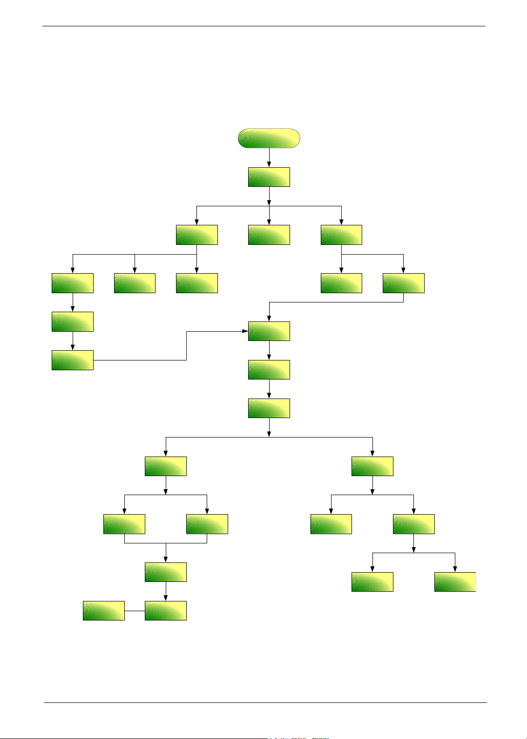
Disassembly Procedure Flowchart
The flowchart on the succeeding page gives you a graphic representation on the entire disassembly sequence
and instructs you on the components that need to be removed during servicing. For example, if you want to
remove the system board, you must first remove the keyboard, then disassemble the inside assembly frame in
that order.
Start
Battery Pack
Thermal
Door
B*1
D*1
System Fan Memory
B*4
Thermal
Module
CPU
F*1
ODD Module
Lower Case
Assembly
D*5
F*1
F*1
Mimi Cover
Middle Cover
F*2
Keyboard
C*2 LCD hinges to logic
D*2 LCD hinges to logic
LCD Module
C*2 on bottom side
C*8 upper case assembly to lower case a ssembly on bottom side
C*2 upper case assembly to lower case assembly on upper side
F*2
HDD Door
H*4
HDD Bracket
Upper Case
Assembly
HDD
Lower Case
Modem
Board
F*1
Main Board
F*2
Speaker Set
Switch Board
(for AS
models)
F*2F*1
Media Board
(for AS
models)
Touchpad
Touchpad
Bracket
F*1
Touchpad
FFC
Chapter 3 59
Page 4
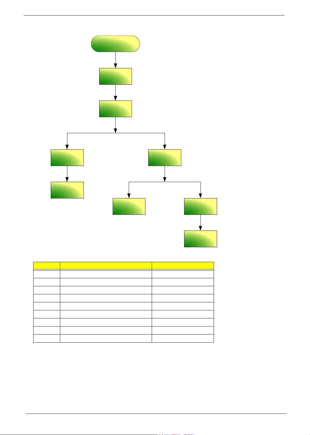
LCD Module
B*4
LCD Bezel
G*1 for 15"
G*2 for 15.4"
LCD Inverter
B*2
LCD Panel
G*2 for 15.4"
LCD
Assembly
Wireless
Antenna Set
LCD Cable
Screw List
Item Description Part Number
A SCREW M2.5*3(NL) 86.TAVV5.001
B SCREW M2.5*6(NL) 86.TAVV5.002
C SCREW M2.5*10(NL) 86.TAVV5.003
D SCREW M2.5*15(NL) 86.TAVV5.004
E SCREW M2*2.2 86.TAVV5.005
F SCREW M2*3(NL) 86.TAVV5.006
G SCREW M2*4 86.TAVV5.007
H SCREW M3*4(NL) 86.TAVV5.008
I SCREW D-SUB 4#X40* 1/5-NI (NL) 86.TAVV5.009
F*8 (4 on left; 4 on right)
LCD Bracket
Sets
LCD
60 Chapter 3
Page 5

Removing the Battery Pack
1. Slide the battery latch then remove the battery.
Chapter 3 61
Page 6

Removing the HDD Module/Memory/System Fan/Thermal Module/ CPU/ODD Module and LCD Module
Removing the HDD Module
1. Remove the two screws fastening the HDD door.
2. Detach the HDD door from the notebook.
3. Pull the HDD module outwards to disconnect the HDD module from the main board.
4. Take out the HDD module carefully.
Removing the Memory/System Fan/Thermal Module/CPU
1. Remove the six screws fastening the thermal door. (M2.5*15(NL) for red circle; M2*3(NL) for yellow circle)
2. Detach the thermal door from the notebook.
3. Pop out the memory then remove it
4. Use a tweezer to take out the fan cable as shown.
5. Disconnect the fan cable from the main board.
62 Chapter 3
Page 7

6. Remove the two screws fastening the system fan.
7. Take out the system fan from the main unit.
8. Remove the four screws fastening the thermal module.
9. Then detach the thermal module carefully.
10. Use a flat-headed screwdriver to release the CPU lock (Turn anti-clockwise).
11. Detach the CPU from the CPU socket carefully.
12. Tear off the tape fastening the antenna set.
13. Then remove the antenna protection cover.
Chapter 3 63
Page 8

14. Remove the screw holding the mini cover.
15. Detach the mini cover from the main unit.
Removing the ODD Module
1. First, remove the screw fastening the ODD module as shown.
2. Push the ODD module outwards then remove it.
Removing the LCD Module
1. Open the LCD module as shown (See the left and the middle picture).
2. Detach the middle cover from the main unit carefully.
3. Remove the screw fastening the keyboard.
4. Then turn over the keyboard as shown.
64 Chapter 3
Page 9

5. Disconnect the keyboard cable from the main board.
6. Turn over the notebook, remove two screws fastening the LCD module on the bottom.
7. Then turn the notebook to the front side. Take out the antenna then disconnect the LCD cable (See the
middle and the right images).
8. Remove four screws fastening the LCD module (M2.5*10(NL) for yellow circles; M2.5*15(NL) for red
circles).
9. Then detach the entire LCD module from the main unit carefully.
Chapter 3 65
Page 10

Disassembling the Main Unit
Separate the Main Unit Into the Upper and the Lower Case Assembly
1. Remove two screws fastening the upper case assembly to the lower case assembly.
2. Disconnect the LED board cable from the main board.
3. Disconnect the touchpad cable from the main board.
4. Remove eight screws fastening the upper case assembly and the lower case assembly on the bottom as
shown.
5. Detach the upper case assembly carefully.
Disassembling the Upper Case Assembly
6. Remove the two screws fastening the media board.
7. Take out the media board cable from the lower case as shown.
8. Detach the media board from the upper case carefully.
NOTE: Only Aspire 5650 series have media board.
9. Tear off the mylar on top of the touchpad bracket.
10. Remove the screws holding the touchpad bracket.
11. Then detach the touchpad bracket from the uppwer case.
66 Chapter 3
Page 11

12. Disconnect the touchpad FFC.
13. Then remove the touchpad FFC from the touchpad.
14. Detach the touchpad from the upper case.
Disassembling the Lower Case Assembly
1. Detach the switch board from the main board.
2. Remove the screw fastening the modem board.
3. Disconnect the modem board from the main board then detach the modem board.
4. Detach the modem cable from the lower case.
5. Disconnect the speaker cable from the main board.
6. Then disconnect the microphone cable from the main baord.
Chapter 3 67
Page 12

7. Remove the screw fastening the main board to the lower case.
8. Pull the lower case outwards as the image shows and detach the main board from the lower case
carefully.
9. Take out the microphone from the lower case.
10. Remove the two screws fastening the speaker set.
11. Take out the speaker from the lower case.
68 Chapter 3
Page 13

Disassembling the LCD Module
1. Remove the four screw caps as shown.
2. Remove the four screws holding the LCD bezel.
3. Then detach the LCD bezel from the LCD module.
4. Remove the screw fastening the LCD inverter.
5. Take out the LCD inverter from the LCD cover, then disconnect the LCD cable from the inverter.
6. Disconnect the LCD power cable on the other side.
7. Remove the two screws fastening the LCD assembly.
8. Take out the LCD assembly from the LCD panel.
9. Tear off the tape fastening the LCD cable.
10. Remove the four screws fastening the LCD right bracket.
11. Remove the LCD right bracket.
Chapter 3 69
Page 14

12. Remove the four screws holding the LCD left bracket.
13. Remove the LCD left bracket.
70 Chapter 3
Page 15

Disassembling the External Modules
Disassembling the HDD Module
1. Remove two screws hodling the HDD bracket on one side.
2. Remove another two screws fastening the HDD bracket on the other side.
3. Detach the HDD from the HDD bracket.
Disassembling the ODD Module
1. Remove the three screws holding the optical bracket.
2. Remove the optical bracket from the optical disk drive.
Chapter 3 71
Page 16

72 Chapter 3
 Loading...