

Page 1

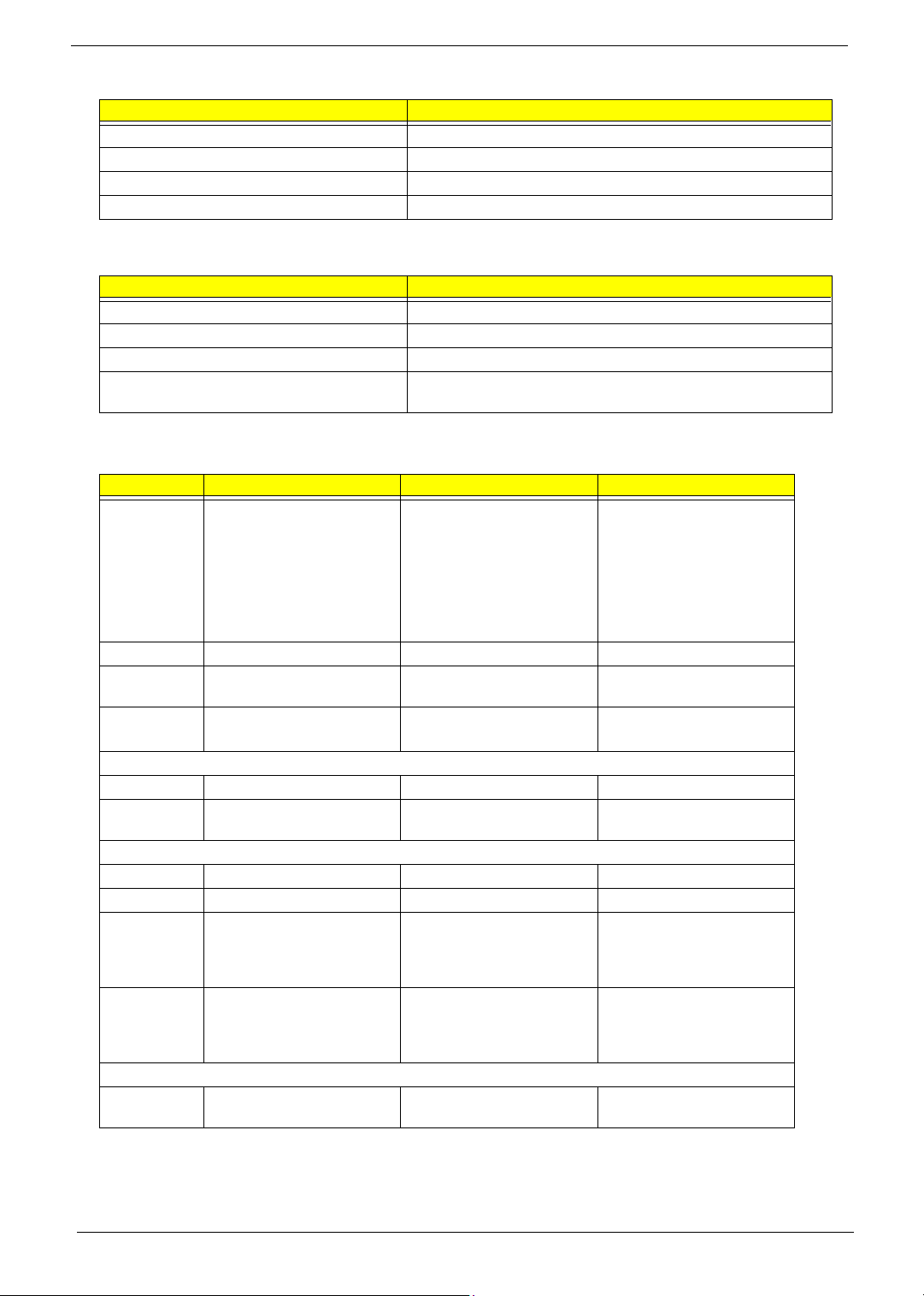
System Specifications
Features
Below is a brief summary of the computer’s many feature:
Platform and memroy
T Intel
T ATI RC410MB/D/E+ATI SB460M
T Integrated Intel
T 256/512 MB of DDR2 533 MHz memory, upgradeable to 2 GB using two so DIMM modules (dual-
Display and graphics
T 15.4” WXGA high-brightness Acer CrystalBrite
T 15” XGA color TFT LCD, 1024x 768 pixel resolution
T ATI Radeon
T Dual independent display
T 16.7 million colors
T MPEG-2/DVD hardware-assisted capability
T Acer CinemaVision
T Acer ClearVision
®
Celeron® M processor 410/420/430 (1MB L2 cache, 1.46/1.6/1.73 GHz, 533 MHz FSB)
®
PRO/Wireless 3945ABG network connection (dual-band tri-mode 802.11a/b/g)
TM
Wi-Fi CERTIFIED
solution, supporting Acer SignalUp
channel support )
supporting simultaneous multi-window viewing via Acer GridVista
®
Xpress 200M integrated 3D graphics with up to 256 MB of shared system memory,
®
supporting Microsoft
and PCI Express
TM
video technology (Acer Arcade) (for Aspire 3650)
TM
video optimization (Acer Arcade) (for Aspire 3650)
Chapter 1
TM
wireless technology
TM
TFT LCD, 1280 x 800 pixel resolution,
®
TM
Storage subsystem
For Aspire 3650:
T 40/60/80/100/120 GB hard disk drive
T Optical drive options:
t DVD-Super Multi double-layer
t DVD/CD-RW combo
For TravelMate 2450:
T 60/80/100/120 GB hard disk drive with Acer Disk Anti-Shock Protection (DASP)
T Optical drive options:
t DVD-Super Multi double-layer
t DVD/CD-RW combo
Input devices
T 88/89-key keyboard
T Touchpad with 4-way scroll button
T 12 function keys
T Four easy-launch buttons
T Two front-access buttons: WLAN LED-button and Bluetooth
Chapter 1 1
®
LED-button
Page 2

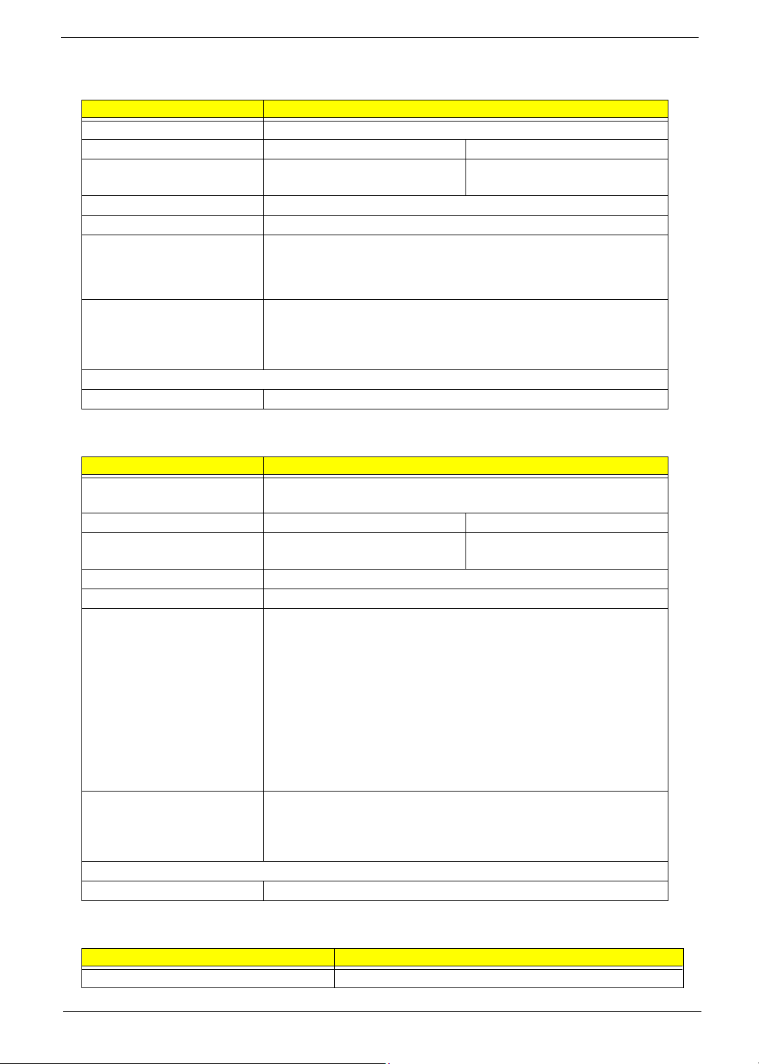
Audio
T Audio system with two built-in speakers (1.5W)
T Intel
T Sound Blaster Pro
T Built-in microphone
Communication
T Modem: 56K ITU V.92 modem with PTT approval; wake-on ring ready
T LAN: 10/100 Mbps Fast Ethernet; wake-on-LAN ready
T WLAN: Acer InviLink
technology
T WPAN: integrated Bluetooth
Power subsystem
T ACPI 2.0 CPU power management standard: supports Standby and Hibernation power-saving
modes
T 29 W 2000 mAh Li-ion battery pack (4-cell)
T 2-hour rapid charge; 2.5-hour charge-in-use
T 3-pin 65W AC adapter
I/O Ports
T PC Card slot (one Type II)
T Three USB 2.0 ports
T External display (VGA) port
T Headphones/speaker/line-out port
T Microphone in jack
T Line-in jack
T Ethernet (RJ-45) port
T Modem (RJ-11) port
T DC-in jack for AC adaptor
®
High-Definition audio support
TM
and MS Sound compatible
TM
802.11b/g Wi-Fi CERTIFIEDTM, supporting Acer SignalUpTM wireless
®
2.0+EDR (Enhanced Data Rate)
Environment
T Temperature:
toperating: 5 C to 35 C
tNon-operating: -20 C to 65 C
T Humidity (non-condensing):
toperating: 20%~80%
tNon-operating: 20%~80%
2 Chapter 1
°°
°°
Page 3
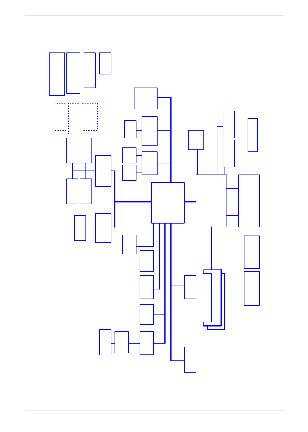
System Block Diagram
Power Circuit DC/DC
DC/DC Interface CKT.
page 37~~43
page 36
CD-PLAY/B Conn.
MEDIA/B Conn.
page 31
page 31
EC I/O Buffer
page 30
BIOS
page 30
page 30
TFDU6102-TR3
FIR
page 28
Power On/Off CKT.
page 13
page 32
Switch/B Conn.
USB port4, 6
page 31
Touch Pad
page 32
ENE KB910Q
page 29
Int.KBD
SMsC LPC47N207
page 28
RTC CKT.
LPC BUS
Super I/O
page 22
page 22
page 24
Slot 0
socket
page 15
page 25
RJ45
6 in 1
S-ATA HDD
Conn.
socket
(WLAN)
(TV-Tuner)
RTL8100/8110
page 23
ENE CB714
page 21
PIDE-HDD
Conn.
page 20
IDSEL:AD18
(PIRQF/H#,
GNT#3,
REQ#3)
Mini PCI
IDSEL:AD22
(PIRQG#,
GNT#1,
REQ#1)
LAN (100/1000)
IDSEL:AD20
(PIRQE#/B#,
GNT#2,
REQ#2)
CardBus
ATI SB460M
page 13~~17
3.3V ATA-100
3.3V 24.576MHz/48Mhz
S-ATA
IDE
3.3V 33 MHz
PCI BUS
3.3V 48MHz
page 25
Alink
Mini card
PCI-Express
LVDS
ATI RC410MB/D/E
uFCBGA-1466
page 7,8,9
1.8V DDRII 400/533/667
Single Channel
page 18
page 19
Memory BUS(DDRII)
LCD Conn.
CRT & TV-out
H_A#(3..31)
uPGA-478 Package
533/667MHz
PSB
page 4,5
H_D#(0..63)
page 4
Fan Control
page 35
Yonah
Thermal Sensor
F75383M
200pin DDRII-SO-DIMM X2
BANK 0, 1, 2, 3
page 10,11
Clock Generator
ICS951413
page 12
Phone Jack x3
page 34
Audio AMP
page 34
SIDE-ODD
page 20
MDC 1.5
Conn
page 31
HDA Codec
ALC883
page 33
HD Audio
USB port 0, 2 on M/B
USB port 4, 6 on PWRBTN/B
USB port1
USB conn x4
page 26
Bluetooth
Conn
page 31
Chapter 1 3
Page 4
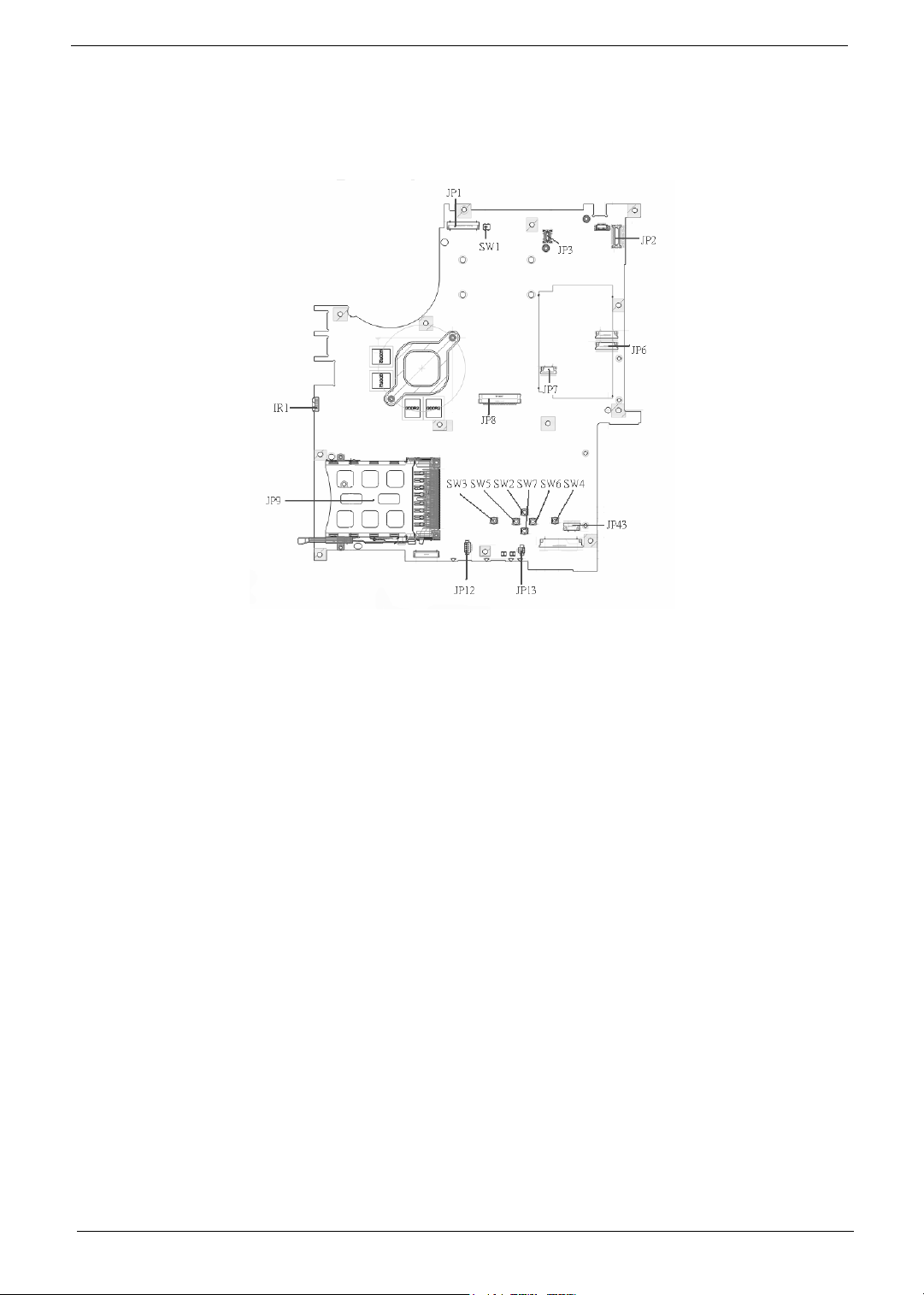
Board Layout
Top View
1 JP1 LCD Connector 10 SW7 Touchpad Down Button
2 SW1 Lid Switch 11 SW2 Touchpad Up Button
3 JP3 MDC Connector 12 SW5 Touchpad Left Button
4 JP2 Power Button Connector 13 SW3 Touchpad Left Button
5 JP6 Media Board Connector 14 JP13 Internal Microphone Connector
6 JP7 Touchpad Board Connector 15 JP12 Internal Speaker Connector
7 JP43 SIM Card Connector 16 JP9 PCMCIA Socket
8 SW4 Touchpad Right Button 17 IR1 FIR Module
9 SW6 Touchpad Left Button 18 JP8 Internal Keyboard Connector
4 Chapter 1
Page 5
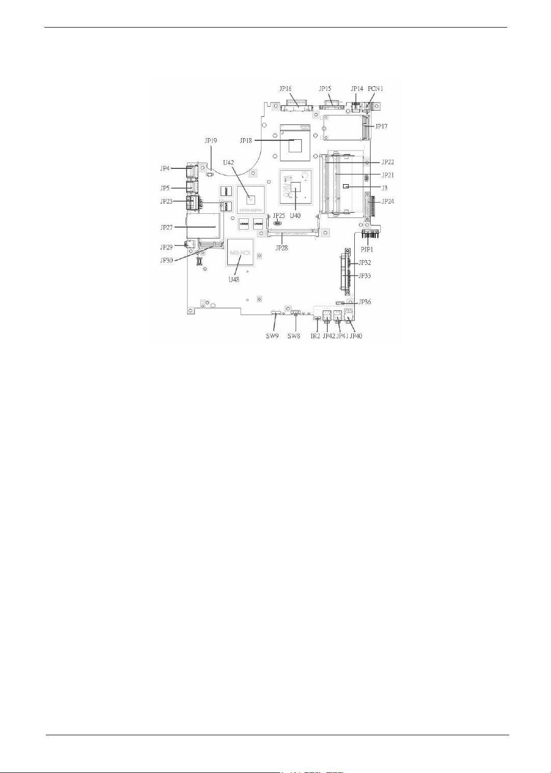
Bottom View
NOTE: This is engineering sample. The image above may not be exactly the same as the real main board you
get.
1 JP19 FAN Connector 17 JP40 Headphone/SPDIF Jack
2 U42 VGA Chipset 18 JP41 Line-In Jack
3 JP18 CPU Socket 19 JP42 Microphone-in Jack
4 JP16 DVI Connector 20 IR2 CIR Module
5 JP15 CRT Connector 21 SW8 Wireless LAN Switch
6 JP14 TV-Out Connector 22 SW9 Bluetooth and 3G Switch
7 PCN1 DC-IN Jack 23 U48 South Bridge Chipset
8 JP17 Mini Card Connector 24 JP30 Mini Card Connector
9 JP22 DDRII so-DIMM Socket 25 JP29 IEEE 1394 Connector
10 JP21 DDRII so-DIMM Socket 26 JP27 5 IN1 Socket
11 J3 Clear CMOS Jumper 27 JP23 RJ45 Connector
12 JP24 ODD Connector 28 JP5 USB Connector
13 PJP1 Battery Connector 29 JP4 USB Connector
14 JP32 HDD Connector (SATA) 30 JP28 MINIPCI Connector (TV-Tuner)
15 JP33 HDD Connector (PATA) 31 JP25 FAN Connector
16 JP36 Bluetooth Connector 32 U40 North Bridge Chipset
Chapter 1 5
Page 6
Jumper Board Layout
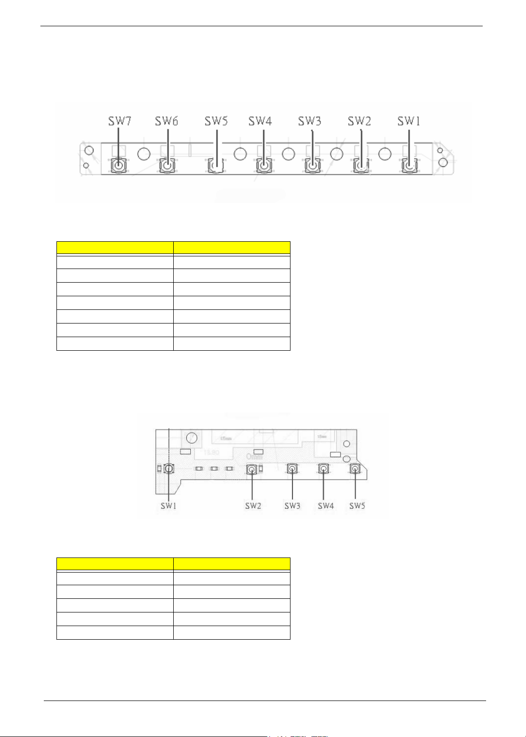
Switch Board Top View
Label Description
SW1 Arcade/TV tuner switch
SW2 Volume Up switch
SW3 Volume Down switch
SW4 Play/Pause switch
SW5 Stop switch
SW6 Forward/Next switch
SW7 Backward/Previous switch
Media Board Top View
Label Description
SW1 Power Button
SW2 E-mail Button
SW3 Internet Button
SW4 User Button
SW5 E-Power Button
6 Chapter 1
Page 7
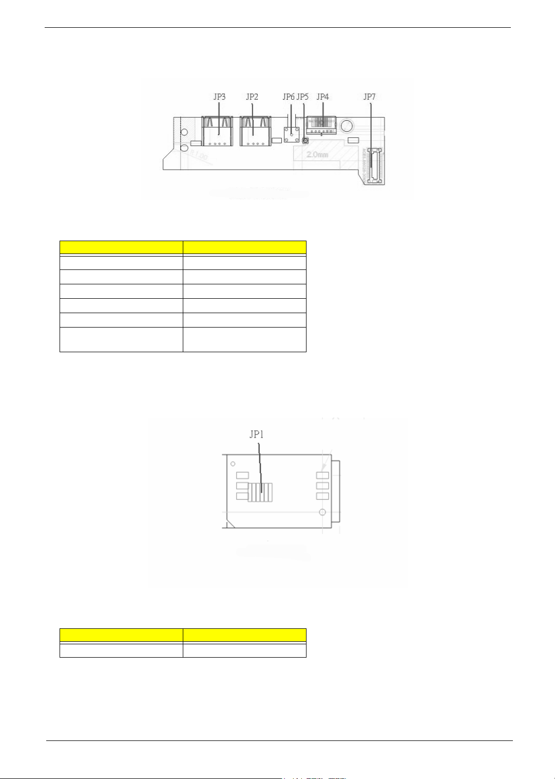
Media Board Bottom View
Label Description
JP3 USB Connector
JP2 USB Connector
JP6 RF INe Connector
JP5 RF Cable Connector
JP4 AV IN Connector
JP7 Board to Main Board
Connector
LS-2923P Power Board Top View
Label Description
JP1 SIM Card Connector
Chapter 1 7
Page 8
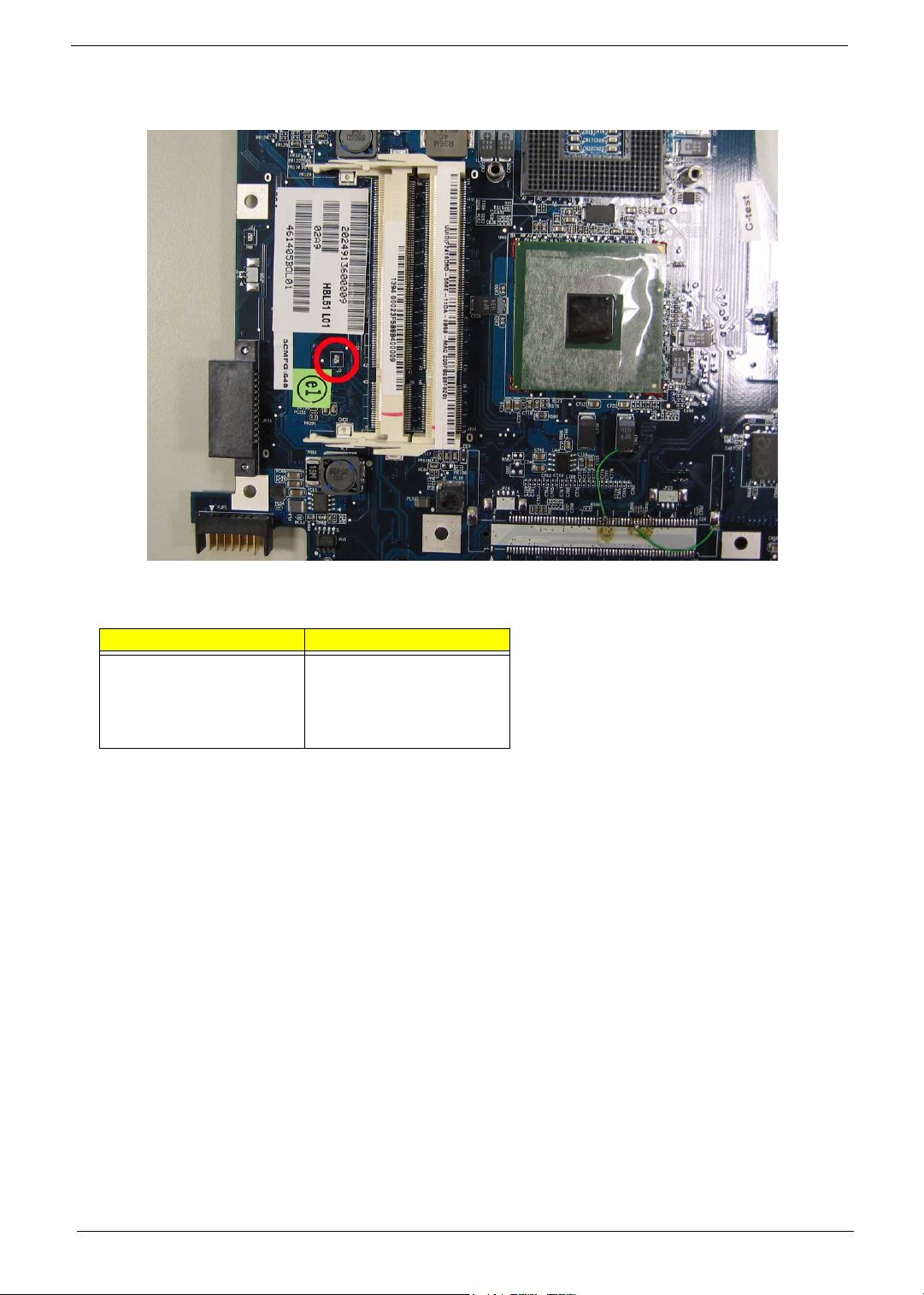
Jumper Setting
Label Description
JOPEN1 Clear CMOS Jumper
Note: JOPEN1 locates at
the bottom side of the main
board as the red circle
highlighted.
8 Chapter 1
Page 9
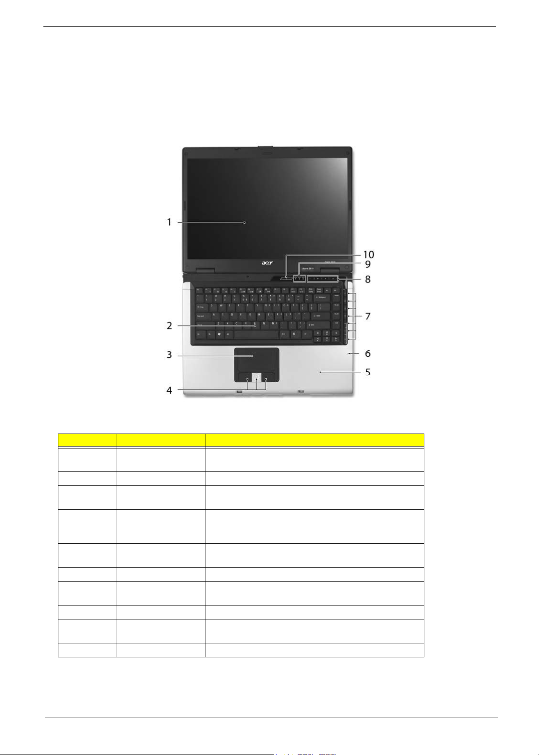
Your Acer Notebook tour
After knowing your computer features, let us show you around your new TravelMate computer.
Front view
Aspire 5610:
# Item Description
1 Display screen Also called LCD (liquid-crystal display), displays computer
2 Keyboard For entering data into your computer.
3 Touchpad Touch-sensitive pointing device which functions like a
4 Click buttons (left,
center and right)
5 Palmrest Comfortable support area for our hands when you use the
6 Microphone Internal microphone for sound recording.
7 TV/media/volume
buttons
8 Easy-launch buttons Buttons for launching frequently used programs.
9 Status indicators Light-Emitting Diodes (LEDs) that light up to show the status
10 Power button Turns the computer on and off.
output.
computer mouse.
The left and right buttons function like the left and right
mouse buttons; the center button serves as a 4-way scroll
button.
computer.
For use with Acer Arcade and other media playing
programs.
of the computer’s functions and components.
Chapter 1 9
Page 10
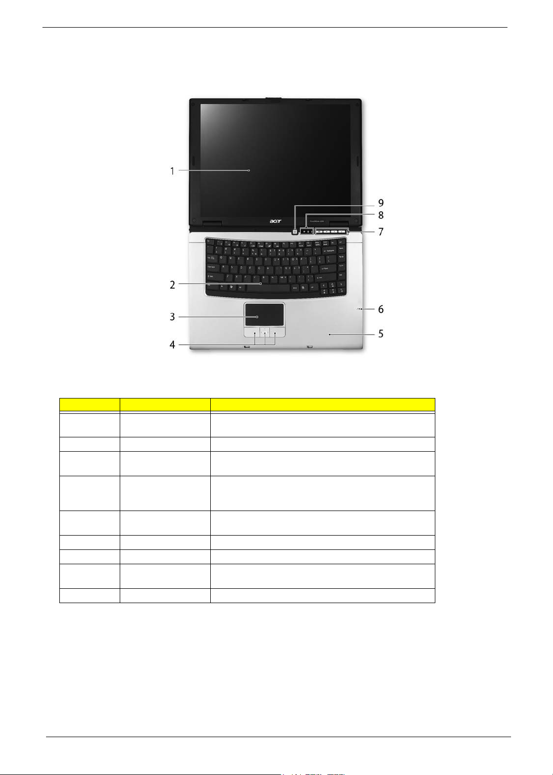
TravelMate 4260:
# Item Description
1 Display screen Also called LCD (liquid-crystal display), displays computer
output.
2 Keyboard For entering data into your computer.
3 Touchpad Touch-sensitive pointing device which functions like a
computer mouse.
4 Click buttons (left,
center and right)
5 Palmrest Comfortable support area for our hands when you use the
6 Microphone Internal microphone for sound recording.
7 Easy-launch Buttons Buttons for launching frequently used programs.
8 Status indicators Light-Emitting Diodes (LEDs) that light up to show the status
9 Power button Turns the computer on and off.
The left and right buttons function like the left and right
mouse buttons; the center button serves as a 4-way scroll
button.
computer.
of the computer’s functions and components.
10 Chapter 1
Page 11
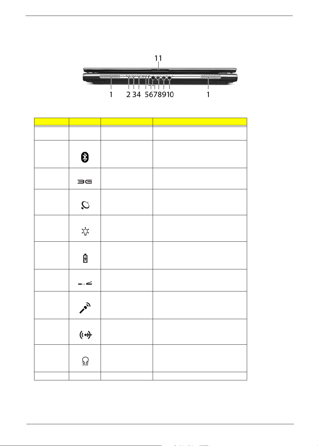
Closed Front View
"Easy-launch buttons" on page 18
"Easy-launch buttons" on page 18
Aspire 5650:
# Icon Item Description
1 Speakers Left and right speakers deliver stereo audio
output.
2
Bluetooth
communication button/
indicator
®
Enable/disable Bluetooth function.
Indicates the status of Bluetoothcommunications.
3 3G switch/indicator Enables/disables the 3G function. Indicates
4 Wireless
communication button/
indicator
5 Power indicator Indicates the computer’s power status.
6 Battery indicator Indicates the computer’s battery status.
7 CIR receiver Receives signals from a remote control.
8 Microphone-in jack Accepts input from external microphones.
9 Line-in jack Accepts audio line-in devices (e.g., audio
the status of 3G communication (for
selected models).
Enable/disable Wireless function. Indicates
the status of wireless LAN
communications.
CD player, stereo walkman).
10 Headphones/
speakers/line-out jack
with S/PDIF support
11 Latch Locks and release the lid.
Connects to audio line-out devices (e.g.,
speakers, headphones).
Chapter 1 11
Page 12
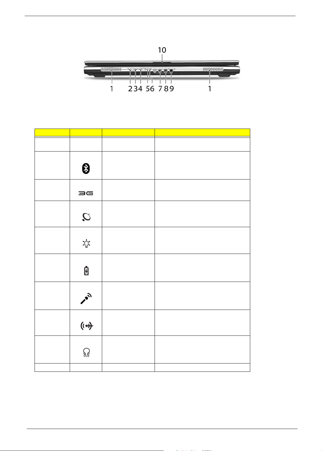
TravelMate 4260:
"Easy-launch buttons" on page 18
"Easy-launch buttons" on page 18
# Icon Item Description
1 Speaker Left and right speakers deliver stereo audio
2
3 3G switch/indicator Enables/disables the 3G function. Indicates
4 Wireless
Bluetooth
communication button/
indicator
communication button/
indicator
®
output.
Enable/disable Bluetooth function.
Indicates the status of Bluetoothcommunications.
the status of 3G communication (for
selected models).
Enable/disable Wireless function. Indicates
the status of wireless LAN
communications.
5 Power indicator Indicates the computer’s power status.
6 Battery indicator Indicates the computer’s battery status.
7 Microphone-in jack Accepts input from external microphones.
8 Line-in jack Accepts audio line-in devices (e.g., audio
CD player, stereo walkman).
9 Headphones/
speakers/line-out jack
with S/PDIF support
10 Latch Locks and release the lid.
Connects to audio line-out devices (e.g.,
speakers, headphones).
Left View
Aspire 5650/TravelMate 4260:
12 Chapter 1
Page 13
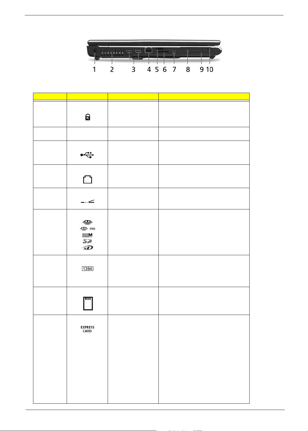
# Icon Item Description
1 Kensington lock slot Connects to a Kensington-compatible
computer security lock.
2 Ventilation slots Enables the computer to stay cool, even
after prolonged use.
3 Two USB 2.0 ports Connects to USB 2.0 devices (e.g., USB
mouse, USB camera).
4 Modem (RJ-11) port Connects to a phone line.
5 Infrared port Interfaces with infrared devices (e.g.,
infrared printer and IR-aware computer).
6 5-in-1 card reader Accepts Memory Stick (MS), Memory Stick
7 4-pin IEEE 1394 port Connects to IEEE 1394 devices.
8 PC Card slot Accepts one Type II PC Card.
9 ExpressCard/34 slot Accepts one ExpressCard/34 module.
PRO (MS PRO), MultiMediaCard (MMC),
Secure Digital (SD), xD-Picture Card (xD).
Note: A 4-pin socket is used for laptop. The
6-pin socket is commonly found on
desktop. As to 9-pin connector, it is for the
faster FireWire 800.
Note: ExpressCards are third generation of
PC cards, hot-swapable and smaller than
previous PC Cards. Designed for both
desktop and mobile use, ExpressCards
use either USB 2.0 or a single lane PCI
Express technology that provides 500
Mbytes/sec total throughput. Formerly
code named "NEWCARD," ExpressCards
are 5 mm thick like Type II PC Cards, but
do not use the same 86x54 mm footprint.
ExpressCards come in 75x54 mm and
75x34 mm sizes. Express Card/34 slot
means this notebook accepts 75x34mm
ExpressCards.
Chapter 1 13
Page 14
10 PC Card slot eject
button
Ejects the PC Card from the slot.
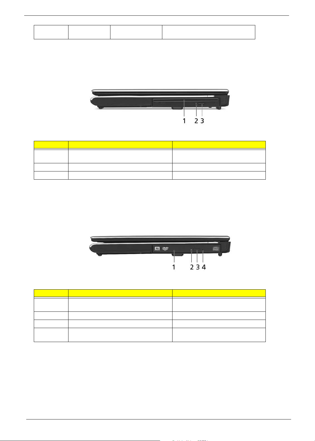
Right View
Aspire 5650:
# Item Description
1 Slot-load optical drive Internal optical drive; accepts CDs or
DVDs.
2 Optical disk access indicator Lights up when the optical drive is active.
3 Slot-loaded optical drive eject button Ejects the optical disk from the drive.
TravelMate 4260:
# Item Description
1 Optical drive Internal optical drive; accepts CDs or
DVDs.
2 Optical disk access indicator Light up when the optical drive is active.
3 Optical drive eject button Ejects the optical disk from the drive.
4 Emergency eject hole Ejects the optical drive tray when the
computer is turned off.
Rear Panel
Aspire 5650:
14 Chapter 1
Page 15

# Icon Item Description
1 Ethernet (RJ-45) port Connects to an Ethernet 10/100/1000-
based network (for selected models).
2 Two USB 2.0 ports Connects to USB 2.0 devices (e.g., USB
3 S-video-in (NTSC/
PAL) port
4 AV-in port Accepts input signals from audio/visual
5 DC-in jack Connects to an AC adapter.
6 S-video/TV-out
(NTSC/PAL) port
7 External display
(VGA) port
8 DVI-D port Supports digital video connections.
9 Ventilation slots Enable the computer to stay cool, even
mouse, USB camera).
Connects to an S-video device like a
DVD player or camcorder.
(AV) devices.
Connects to a television or display
device with S-video input.
Connects to a display device(e.g.,
external monitor, LCD projector).
after prolonged use.
TravelMate 4260:
Chapter 1 15
Page 16

# Icon Item Description
1 Ethernet (RJ-45) port Connects to an Ethernet 10/100/1000-
based network (for selected models).
2 Two USB 2.0 ports Connects to USB 2.0 devices (e.g., USB
mouse, USB camera).
3 DC-in jack Connects to an AC adapter.
4 S-video/TV-out
(NTSC/PAL) port
5 External display
(VGA) port
6 DVI-D port Supports digital video connections.
7 Ventilation slots Enable the computer to stay cool, even
Connects to a television or display
device with S-video input.
Connects to a display device(e.g.,
external monitor, LCD projector).
after prolonged use.
Base view
Aspire 5650/TravelMate 4260:
# Item Description
1 Battery lock Locks the battery in position.
2 Battery bay Helps keep the computer cool.
Note: Do not cover or obstruct the opening
of the fan.
3 Hard disk bay Houses the computer’s hard disk (secured
with screws)
16 Chapter 1
Page 17

4 Acer DASP (Disk Anti-
Shock Protection)
5 Memory compartment Houses the computer’s main memory.
6 Ventilation slots and
cooling fan
Protects the hard disk drive from shocks
and bumps. (for TravelMate 4260 only)
Release the battery for removal.
Indicators
The computer has four easy-to-read status indicators on the upper-right above the keyboard, and four on the
front panel.
Aspire 5650:
TravelMate 4260:
The power, battery and wireless communication status indicators are visible even when the LCD display is
closed.
Chapter 1 17
Page 18

Icon Function Description
HDD Indicators when the hard disk drive is
active.
Cap lock Lights when Cap Lock is activated
Num lock Lights when Num Lock is activated.
Bluetooth Indicates the status of Bluetooth
communication.
3G Indicates the status of 3G
communication.
Wireless LAN Indicates the status of wireless LAN
communication.
Power Indicates the computer’s power status.
Battery Indicates the computer’s battery status.
NOTE: 1. Charging: The light shows amber when the battery is charging. 2. Fully charged: The light shows
green when in AC mode.
Easy-Launch Buttons
Located above the keyboard are four buttons. These buttons are called easy-launch buttons. They are: mail
Web browser, Empowering Key “ “and one user-programmable button.
Press “ “ to run the Acer Empowering Technology. The mail and Web browser buttons are pre-set to email
and Internet programs, but can be reset by users. To set the Web browser, mail and programmable buttons,
run the Acer Launch Manager.
Aspire 5650:
18 Chapter 1
Page 19
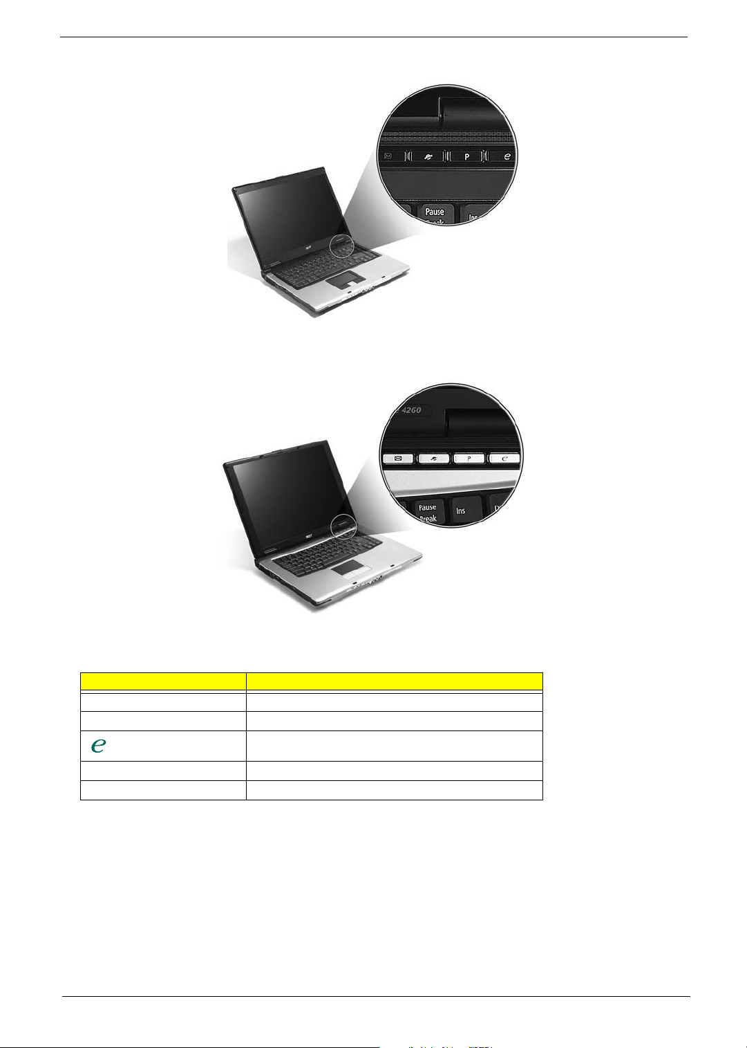
TravelMate 4260:
Launch key Default application
P User-programmable
P User-programmable
Acer Empowering Technology (user-programmable)
Web browser Internet browser (user-programmable)
Mail Email application (user-programmable)
Chapter 1 19
Page 20

Using the Keyboard
The keyboard has full-sized keys and an embedded keypad, separate cursor keys, two Windows keys and
twelve function keys.
Lock Keys and embedded numeric keypad
The keyboard has three lock keys which you can toggle on and off.
Aspire 5650:
TravelMate 4260:
Lock Key Description
Caps Lock When Caps Lock is on, all alphabetic characters typed
Num lock
<Fn>+<F11>
Scroll lock
<Fn>+<F12>
are in uppercase.
When Num Lock is on, the embedded keypad is in
numeric mode. The keys function as a calculator
(complete with the arithmetic operators +, -, *, and /).
Use this mode when you need to do a lot of numeric
data entry. A better solution would be to connect an
external keypad.
When Scroll Lock is on, the screen moves one line up
or down when you press the up or down arrow keys
respectively. Scroll Lock does not work with some
applications.
The embedded numeric keypad functions like a desktop numeric keypad. It is indicated by small characters
located on the upper right corner of the keycaps. To simplify the keyboard legend, cursor-control key symbols
are not printed on the keys.
Desired Access Num Lock On Num Lock Off
Number keys on embedded
keypad
Cursor-control keys on
embedded keypad
Type numbers in a normal
manner.
Hold <Shift> while using
cursor-control keys.
Hold <Fn> while using
cursor-control keys.
20 Chapter 1
Page 21

Desired Access Num Lock On Num Lock Off
Main keyboard keys Hold <Fn> while typing
letters on embedded
keypad.
Type the letters in a normal
manner.
Windows Keys
The keyboard has two keys that perform Windows-specific functions.
Key Icon Description
Windows key Pressed alone, this key has the same effect as
clicking on the Windows Start button; it launches the
Start menu. It can also be used with other keys to
provide a variety of function:
+ <Tab> Activates next taskbar button.
+ <E> Opens the My Computer window
+ <F1> Opens Help and Support.
+ <F> Opens the Find: All Files dialog box.
+ <R> Opens the Run dialog box.
+ M Minimizes all windows.
<Shift>+ + <M> Undoes the minimize all windows
action.
This key has the same effect as clicking the right
Applicati
on key
mouse button; it opens the application’s context
menu.
Hot Keys
The computer employs hotkeys or key combinations to access most of the computer’s controls like screen
brightness, volume output and the BIOS utility.
To activate hot keys, press and hold the <Fn> key before pressing the other key in the hotkey combination.
Aspire 5650:
TravelMate 4260:
Chapter 1 21
Page 22
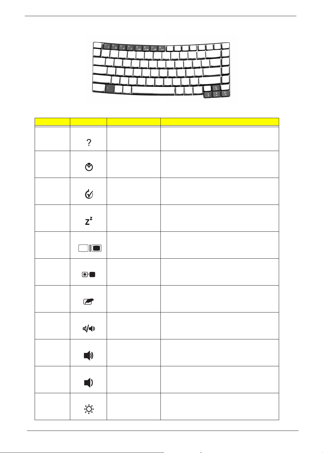
Hot Key Icon Function Description
Fn-F1 Hot key help Displays help on hot keys.
Fn-F2 Acer eSetting Launches the Acer eSettings in Acer eManager.
Fn-F3 Acer
ePowerManagement
Fn-F4 Sleep Puts the computer in Sleep mode.
Fn-F5 Display toggle Switches display output between the display screen,
Fn-F6 Screen blank Turns the display screen backlight off to save power.
Fn-F7 Touchpad toggle Turns the internal touchpad on and off.
Fn-F8 Speaker toggle Turns the speakers on and off.
Fn-w Volume up Increases the speaker volume.
Launches the Acer ePowerManagement in Acer
eManager.
external monitor (if connected) and both.
Press any key to return.
Fn-y Volume down Decreases the speaker volume.
Fn-x Brightness up Increases the screen brightness.
22 Chapter 1
Page 23

Hot Key Icon Function Description
Fn-z Brightness down Decreases the screen brightness
Special Key
You can locate the Euro symbol and US dollar sign at the upper-center and/or bottom-right of your keyboard.
To t y p e:
Aspire 5650:
TravelMate 4260:
The Euro symbol
1. Open a text editor or word processor.
2. Either directly press the <> symbol at the bottom-right of the keyboard, or hold <Alt Gr> and then
press the<5> symbol at the upper-center of the keyboard.
The US dollar sign
1. Open a text editor or word processor.
2. Either directly press the <> key at the bottom-right of the keyboard, or hold <Shift> and then press the
<4> key at the upper-center of the keyboard.
NOTE: This function varies by the operating system version.
NOTE: Some fonts and software do not support the Euro symbol. Please refer to www.microsoft.com/
typography/faq/faq12.htm for more information.
Chapter 1 23
Page 24
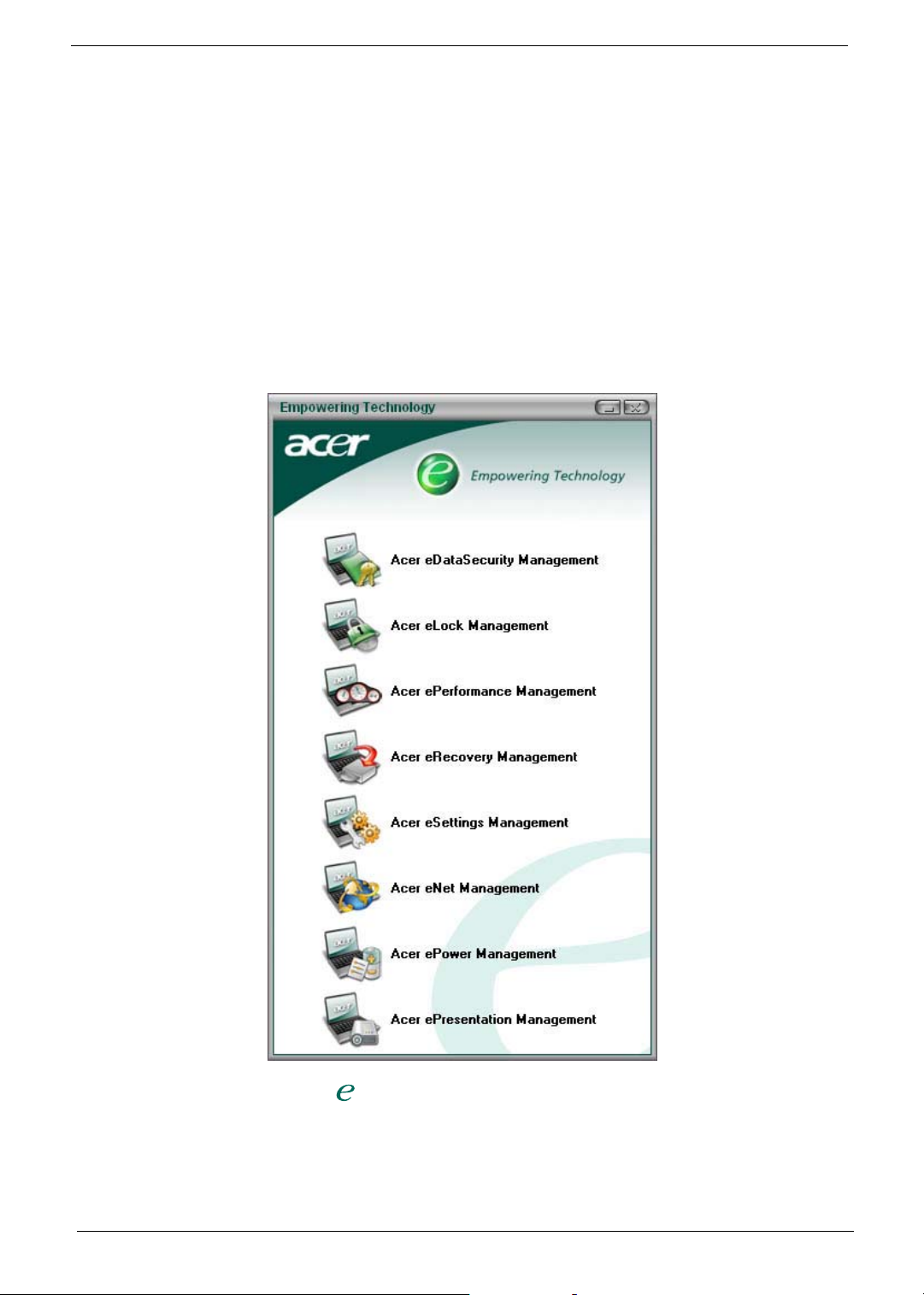
Acer Empowering Technology
Acer’s innovative Empowering Technology makes it easy for you to access frequently used functions and
manage your new Acer notebook. It features the following handy utilities:
T Acer eDataSecurity Management protects data with passwords and advanced encryption algorithms.
T Acer eLock Management limits access to external storage media.
T Acer ePerformance Management improves system performance by optimizing disk space, memory and
registry settings.
T Acer eRecovery Management backs up/recovers data flexibly, reliably and completely.
T Acer eSettings Management accesses system information and adjusts settings easily.
T Acer eNet Management hooks up to location-based networks intelligently.
T Acer ePower Management extends battery power via versatile usage profiles.
T Acer ePresentation Management connects to a projector and adjusts display settings conveniently.
For more information, press the < > key to launch the Empowering Technology menu, then click on the
appropriate utility and select the Help function.
Acer eDataSecurity Management
Acer eDataSecurity Management is handy file encryption utility that protects your files from being accessed by
unauthorized persons. It is conveniently integrated with Windows explorer as a shell extension for quick and
24 Chapter 1
Page 25
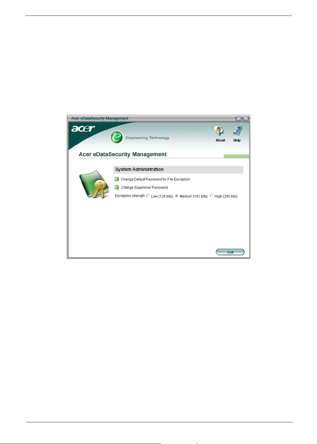
easy data encryption/decryption and also supports on-the-fly file encryption for MSN Messager and Microsoft
Outlook.
There are two passwords that can be used to encrypt/decrypt a file; the supervisor password and the filespecific password. The supervisor password is a “master” password that can decrypt any file on your system;
the file-specific password will be used to encrypt files by default, or you can choose to enter your own filespecific password when encrypting a file.
NOTE: The password used encrypt a file is the unique key that the system needs to decrypt it. If you lose the
password, the supervisor password is the only other key capable of decrypting the file. If you lose both
passwords, there will be no way to decrypt your encrypted file! Be sure to safeguard all related
passwords!
Chapter 1 25
Page 26

Acer eLock Management
Acer eLock Management is a security utility that allows you to lock up your removable data, optical and floppy
drives to ensure that data can’t be stolen while your notebook is unattended.
T Removable data devices - includes USB disk drives, USB pen drives, USB flash drives, USB MP3 drives,
USB memory card readers, IEEE 1394 disk drives and any other removable disk drives that can be
mounted as a file system when plugged into the system.
T Optical drive devices - includes any kind of CD-ROM or DVD-ROM drives.
T Floppy disk drives - 3.5-inch disks only.
To activate Acer eLock Management, a password must be set first. Once set, you may apply lock to any of the
three kinds of devices. Lock(s) will immediately be set without any reboot necessary, and will remain locked
after rebooting, until unlocked.
If you do not set a password, Acer eLock Management will reset back to the initial status with all locks
removed.
NOTE: If you lose your password, there is no method to reset it except by reformatting your notebook or taking
your notebook to an Acer Customer Service Center. Be sure to remember or write down your password.
26 Chapter 1
Page 27

Acer ePerformance Management
Acer ePerformance Management is a system optimization tool that boosts the performance of your Acer
notebook. It provides you with the following options to enhance overall system performance:
T Memory optimization - releases unused memory and check usage.
T Disk optimization - removes unneeded items and files.
T Speed optimization - improves the usability and performance of your Windows XP system.
Chapter 1 27
Page 28

Acer eRecovery Management
Acer eRecovery Management is a powerful utility that does away with the need for recovery disks provided by
the manufacturer. The Acer eRecovery Management utility occupies space in a hidden partition on your
system’s HDD. User-created backups are stored on D:\ drive. Acer eRecovery Management provides you
with:
T Password protection.
T Recovery of applications and drivers.
T Image/data backup:
T Back up to HDD (set recovery point).
T Back up to CD/DVD.
T Image/data recovery tools:
T Recover from a hidden partition (factory defaults).
T Recover from the HDD (most recent user-defined recovery point).
T Recover from CD/DVD.
28 Chapter 1
Page 29

NOTE: If your computer did not come with a Recovery CD or System CD, please use Acer eRecovery
Management’s “System backup to optical disk” feature to burn a backup image to CD or DVD. To
ensure the best results when recovering your system using a CD or Acer eRecovery Management,
detach all peripherals (except the external Acer ODD, if your computer has one), including your Acer
ezDock.
Acer eSettings Management
Acer eSettings Management allows you to inspect hardware specifications and to monitor the system health
status. Furthermore, Acer eSettings Management enables you to optimize your Windows operating system, so
your computer runs faster, smoother and better.
Acer eSettings Management also:
T Provides a simple graphical user interface for navigating through the program effortlessly.
T Displays general system status and advanced monitoring for power users.
T Logs when a hardware component has been removed or replaced.
T Permits you to migrate personal settings.
T Keeps a history log of all alerts that were previously issued.
Chapter 1 29
Page 30

Acer eNet Management
Acer eNet Management helps you to quickly and easily connect to both wired and wireless networks in a
variety of locations. To access this utility, either click on the “Acer eNet Management” icon on your notebook,
or start the program from the Start menu. You also have the option to set Acer eNet Management to start
automatically when you boot up your PC.
Acer eNet Management automatically detects the best settings for a new location, while offering you the
freedom to manually adjust the settings to match your needs, simply by right-clicking on the icon in the taskbar.
Acer eNet Management can save network settings for a location to a profile, and automatically apply the
appropriate profile when you move from one location to another. Settings stored include network connection
30 Chapter 1
Page 31

settings and DNS settings, wireless AP details, etc.), as well as default printer settings. Security and safety
concerns mean that Acer eNet Management does not store username and password information.
Acer ePower Management
Acer ePower Management features a straightforward user interface. To launch it, select Acer ePower
Management from the Empowering Technology interface, or double-click the Acer ePower Management icon
in the task tray.
Acer Mode
The default setting is “Maximum Performance.” You can adjust CPU speed, LCD brightness and other
settings, or click on buttons to turn the following functions on/off: Wireless LAN, Bluetooth, CardBus, Memory
Card, Audio, and Wired LAN.
DC Mode
To suit your usage, there are four pre-defined profiles - Entertainment, Presentation, Word Processing, and
Maximum Battery. Or, you can define up to three of your own profiles.
Create new power scheme
1. Assign a name for the new scheme.
2. Choose existing scheme to use as a template.
3. Select whether used for mains (AC) or battery mode.
4. Choose which power options best fit your needs, then click OK.
5. The new profile will appear on the main screen.
Battery status
For real-time battery life estimates based on current usage, refer to the panel on the lower left-hand side of the
window.
Chapter 1 31
Page 32

You can also click “Advanced Settings” to:
T Set alarms.
T Re-load factory defaults.
T Select what actions will be taken when the cover is closed, and set passwords for accessing the system
after Hibernation or Standby.
T View information about Acer ePower Management.
32 Chapter 1
Page 33

Acer ePresentation Management
Acer ePresentation Management lets you select from two of the most common projector resolutions: XGA and
SVGA.
Chapter 1 33
Page 34

Hardware Specifications and Configurations
Processor
Item Specification
®
CPU type
Core logic
CPU package
CPU core voltage
Intel
1.66/1.83/2/2.16GHz, 667 MHz FSB)
Intel
µ
FCBGA-1466
BIOS
Item Specification
BIOS vendor Phoenix
BIOS Version V1.10
BIOS ROM type 512K Flash ROM
BIOS ROM size 1MB Flash BIOS
BIOS package 32-pin PLCC
Supported protocols ACPI 1.0b/2.0/3.0, PCI2.2, System/HDD Password Security Control, INT
13h Extensions, PnP 1.0a, SMBIOS 2.4, BIOS Boot Specification
(Compaq, Phoenix, INtel), Simple Boot Flag 1.0, Boot Block, PCI Bus
Power Management Interface Specifications USB1.1/2.0, PC Card 95,
IrDA 1.0, Intel AC97 CNR Specification, WfM 2.0, PXE 2.1, Boot Integrity
Service Application Program Interface (BIS) 1.0, PC99a and Mobile
PC2001 Compliant, Intel (R) SpeedStep Technology, Legacy 1394 Device
support, DMI 2.0, PS/2 keyboard and mouse
BIOS password control Set by setup manual
Second Level Cache
TM
Core
®
945GM/945PM+ICH7-M
Duo processor T2300/T2400/T2500/T2600 (2 MB L2 cache,
Item Specification
Cache controller Built-in CPU
Cache size
1st level cache control Always enabled
2st level cache control Always enabled
Cache scheme control Fixed in write-back
2MB for Intel
®
Pentium® M 945GM/945PM Processor
System Memory
Item Specification
Memory controller
Memory size 0MB (no on-board memory)
DIMM socket number 2 sockets
Supports memory size per socket 1024MB
Supports maximum memory size 2G (by two 1024MB SO-DIMM module)
Supports DIMM type DDR 2 Synchronous DRAM
Supports DIMM Speed 533 MHz
Supports DIMM voltage 1.8V
Supports DIMM package 200-pin soDIMM
Memory module combinations You can install memory modules in any combinations as long as they
Built-in Intel
match the above specifications.
®
945GM/945PM
34 Chapter 1
Page 35

Memory Combinations
Slot 1 Slot 2 Total Memory
0MB 128MB 128MB
0MB 256MB 256MB
0MB 512MB 512MB
0MB 1024MB 1024MB
128MB 128MB 256MB
128MB 256MB 384MB
128MB 512MB 640MB
128MB 1024MB 1152MB
256MB 128MB 384MB
256MB 256MB 512MB
256MB 512MB 768MB
256MB 1024MB 1280MB
512MB 128MB 640MB
512MB 256MB 768MB
512MB 512MB 1024MB
512MB 1024MB 1536MB
1024MB 0MB 1024MB
1024MB 128MB 1152MB
1024MB 256MB 1280MB
1024MB 512MB 1536MB
1024MB 1024MB 2048MB
NOTE: Above table lists some system memory configurations. You may combine DIMMs with various
capacities to form other combinations. On above table, the configuration of slot 1 and slot 2 could be
reversed.
LAN Interface
Item Specification
Chipset BroadCom BCM4401E
Supports LAN protocol 10/100Mbps
LAN connector type RJ45
LAN connector location Right side
Features Integrated 10/100 BASE-T transceiver
Wake on LAN support compliant with ACPI 2.0
PCI v2.2
Modem Interface
Item Specification
Data modem data baud rate (bps) 56K
Supports modem protocol V.90/V.92
Modem connector type RJ11
Modem connector location Right side
Bluetooth Interface
Item Specification
Chipset
Built-in Intel
®
ICH7-M
Chapter 1 35
Page 36
Bluetooth Interface
Item Specification
Data throughput 723 bps (full speed data rate)
Protocol Bluetooth 2.0
Interface USB 1.1
Connector type Mini-USB
Wireless Module 802.11b/g (optional device)
Item Specification
Chipset Built-in ICH7-M
Data throughput 11~54 Mbps
Protocol 802.11b+g
Interface Mini-PCI type II (What does PCI Bus means on the system block
diagram?)
Hard Disk Drive Interface
Item
Vendor &
Model Name
Capacity (MB) 40000 60000 80000
Bytes per
sector
Data heads 2 3 (for Hitachi and Seagate)
Drive Format
Disks 1 2 2
Spindle speed
(RPM)
Performance Specifications
Buffer size 2048KB 8192KB 8192KB
Interface ATA/ATAPI-6; ATA-6 ATA/ATAPI-6; ATA-6 ATA/ATA-6; ATA-6
Max. media
transfer rate
(disk-buffer,
Mbytes/s)
Data transfer
rate
(host~buffer,
Mbytes/s)
DC Power Requirements
Voltage
tolerance
Seagate 40G ST9402112A
Toshiba MK4025GAS
Hitachi HTS421240H9AT00
WD WD400UE-22HCT0
Samsung M40MP0402H
512 512 512
4200 RPM 4200 RPM 4200 RPM
372 350 350
100 MB/Sec.
Ultra DMA mode-5
5V(DC) +/- 5% 5V(DC) +/- 5% 5V(DC) +/- 5%
Seagate ST96812A
Seagate ST960821A
Toshiba MK6025GAS
HGST HTS541260H9AT00
WD WD600UE-22HCT0
4 (for Toshiba)
100 MB/Sec.
Ultra DMA mode-5
TOSHIBA MK8025GAS
HITACHI HTS421280H9AT00
SEAGATE ST9808210A
SEAGATE ST98823A
TOSHIBA MK8026GAX
HGST HTS541280H9AT00
WD WD800UE-22HCT0
4 (for Hitachi)
3 (for Seagate)
100 MB/Sec.
Ultra DMA mode-5
36 Chapter 1
Page 37
Combo Drive Interface
Item Specification
Vendor & model name DVD/CDRW HLDS GCC-4244N
Performance Specification With CD Diskette With DVD Diskette
Transfer rate (KB/sec) Sustained:
Max 3.6Mbytes/sec
Buffer Memory 2MB
Interface Enhanced IDE(ATAPI) compatible
Applicable disc format DVD: DVD-ROM, (DVD-5, DVD-9, DVD-10, DVD-18),DVD-R (read, single
border), DVD-RW, DVD-RAM (2.6GB, 4.7GB)
CD: CD-DA, CD-ROM, CD-ROM XA, CD-R, CD-RW Photo (Multisession) Video
CD, CD-Extra, (CD+), CD-test
Loading mechanism Load: Manual
Release: (a) Electrical Release (Release Button)
(b) Release by ATAPI command
(c) Emergency Release
Power Requirement
Input Voltage 5 V +/- 5% (Operating)
Sustained:
Max 10.8Mbytes/sec
DVD-Dual Interface
Item Specification
Vendor & model name LITEON SOSW-833S
PIONEER DVR-K16RA
Performance Specification With CD Diskette With DVD Diskette
Transfer rate (KB/sec) Sustained:
Max 3.6Mbytes/sec
Buffer Memory 2MB
Interface Enhanced IDE(ATAPI) compatible
Applicable disc format Support disc formats
1. Reads data in each CD-ROM, CD-ROM XA, CD-1, Video CD, CD-Extra and
CD-Text
2. Reads data in Photo CD (single and Multi-session)
3. Reads standard CD-DA
4. Reads and writes CD-R discs
5. Reads and writes CD-RW discs
6. Reads and writes in each DVD+R/RW (Ver. 1.1)
7. Reads data in each DVD-ROM and DVD-R (Ver. 2.0 for Authoring)
8. Reads and writes in each DVD-R (Ver. 2.0 for general), DVD-RW and
DVD+R/RW (Ver1.1)
Loading mechanism Load: Manual
Release: (a) Electrical Release (Release Button)
(b) Release by ATAPI command
(c) Emergency Release
Power Requirement
Input Voltage 5 V +/- 5% (Operating)
Sustained:
Max 10.8Mbytes/sec
HD Audio Interface
Item Specification
Audio Controller ALC883
Chapter 1 37
Page 38

HD Audio Interface
Item Specification
Audio onboard or optional Built-in
Mono or Stereo Stereo
Resolution Wide range (°V80dB ~ +42dB) volume control with 1.5dB
resolution of analog to analog mixer gain
16 bit stereo digital to analog converter
16 bit stereo analog to digital converter
Compatibility HD Audio
Mixed sound source Line-in, CD
Voice channel 8/16-bit, mono/stereo
Sampling rate All DACs support 44.1k/48k/96k/192kHz sample rate
All ADCs support 44.1k/48k/96kHz sample rate
16/20/24-bit S/PDIF-OUT supports 44.1k/48k/96k/192kHz sample
rate
16/20/24-bit S/PDIF-IN supports 44.1k/48k/96kHz sample rate
Internal microphone Yes
Internal speaker / Quantity Yes/2
Video Interface
Item Specification
Chipset
Package 35.5 mm x 40 mm 1257 pin mBGA
Interface internal PCIE
Supports ZV (Zoomed Video) port Yes
Memory Interface 64-bit
Memory Bandwidth(GB/sec) 5.6
Fill Rate (Gpixels/sec) 1.4
Vertices/Second (Millions) 260
Memory Data Rate (MHz) 700
RAMDACs (MHz) 400
Built-in Intel
NVIDIA
®
945GM for UMA models
®
GeForce® Go 7600 (72MV) for discrete models
NOTE: RAMDAC refers to Random Access Memory Digital to Analog Converter: the VGA controller chip that
maintains the range of colors and converts data from memory into analog signals for the monitor.
Video Memory
Item Specification
Chipset
Memory size 128MB/256MB (256MB for Aspire 5650 only)
Interface GDDR2
Built-in Intel
NVIDIA
®
945GM for UMA models
®
GeForceTM Go 7600 for discrete models
USB Port
Item Specification
Chipset Built-in ICH7M
USB Compliancy Level 2.0
OHCI USB 1.1 and USB 2.0 Host controller
38 Chapter 1
Page 39

USB Port
Item Specification
Number of USB port 3
Location Three on the right side
Serial port function control Enable/Disable by BIOS Setup
PCMCIA Port
Item Specification
PCMCIA controller ENE CB714
Supports card type Type-II
Number of slots One type-II
Access location Left panel
Supports ZV (Zoomed Video) port No ZV support
Supports 32 bit CardBus Yes
System Board Major Chips
Item Controller
Core logic
VGA
LAN ENE BCM4401E
USB 2.0 Built in ICH7-M
Super I/O controller SMsC LPC47N207
MODEM Built-in ICH7-M
Bluetooth Built-in ICH7-M
Wireless 802.11 b+g Built-in ICH7-M
PCMCIA ENE CB714
HD Audio Realtek ALC883
®
945GM/945PM+ICH7M
Intel
®
Built in Intel
NVIDIA
945GM for UMA models
®
GeForceTM Go 7600 for discrete models
Keyboard
Item Specification
Keyboard controller ENE KB 910Q
Total number of keypads 88-/89-key
Windows logo key Yes
Internal & external keyboard work
simultaneously
Plug USB keyboard to the USB port directly: Yes
Battery
Item Specification
Vendor & model name Sony (8cell)
Sanyo (8cell)
Battery Type Li-ion
Pack capacity 4800 mAH
Number of battery cell 8
Package configuration 4 cells in series, 2 series in parallel
Chapter 1 39
Page 40

Battery
Item Specification
Normal voltage 14.8V
Charge voltage 16.8+-0.2v
LCD 14.1” inch
Item Specification
Vendor & model name AU B141EW01 CMO N141I1-
L02
Screen Diagonal (mm) 14.1 inches 14.1 inches 14.1 inches 14.1 inches
Active Area (mm) 304.1x228.1 304.1x228.1 304.1x228.1
Display resolution (pixels) 1024x768 XGA 1024x768 XGA 1024x768 XGA
Pixel Pitch 0.297x0.297 0.099x0.297 0.297x0.297
Pixel Arrangement R.G.B. Vertical
Stripe
Display Mode Normally White Normally White Normally White
2
Typical White Luminance (cd/m
also called Brightness
Luminance Uniformity N/A N/A 70
Contrast Ratio 300 300 250
Response Time (Optical Rise Time/Fall
Time)msec
Nominal Input Voltage VDD +3.3V Typ. +3.3V 3.3V
Typical Power Consumption (watt) 5.6/5.7 3.96 N/A
Weight 550 570 600
Physical Size(mm) 317.3x242.0x6.0317.3x242.0x5.9317.3x242.0x6.
Electrical Interface 1 channel LVDS 1 channel LVDS 1 channel LVDS
Support Color 262K colors
Viewing Angle (degree)
Horizontal: Right/Left
Vertial: Upper/Lower
Temperature Range( C)
Operating
Storage (shipping)
°
)
180 (5 point
average)
150 (5 point
average)
24/11
15/35
(RGB 6-bit data
driver)
40/40
10/30
0 to +50
-20 to +60
R.G.B. Vertical
Stripe
160 150
8/17 10/25
262,144 262,144
45/45
15/35
0 to +50
-25 to +60
QDI
QD14TL01-03
R.G.B. Vertical
Stripe
5
40/40
20/40
0 to +50
-20 to +60
SAMSUNG
LTN141W1-L01
LCD Inverter
Item Specification
Vendor & model name Darfon/V189-301GP
Brightness conditions N/A
Input voltage (V) 9~21
Input current (mA) 2.56 (max)
Output voltage (V, rms) 780V (2000V for kick off)
Output current (mA, rms) 6.5 (max)
Output voltage frequency (k Hz) 65K Hz (max)
40 Chapter 1
Page 41

AC Adaptor
Item Specification
Input rating 90V AC to 264V AC, 47Hz to 63Hz
Maximum input AC current 1.7A
Inrush current 220A@115VAC
220A@230VAC
Efficiency 82% min. @115VAC input full load
System Power Management
ACPI mode Power Management
Mech. Off (G3) All devices in the system are turned off completely.
Soft Off (G2/S5) OS initiated shutdown. All devices in the system are turned off
completely.
Working (G0/S0) Individual devices such as the CPU and hard disc may be power
managed in this state.
Suspend to RAM (S3) CPU set power down
VGA Suspend
PCMCIA Suspend
Audio Power Down
Hard Disk Power Down
CD-ROM Power Down
Super I/O Low Power mode
Save to Disk (S4) Also called Hibernation Mode. System saves all system states and
data onto the disc prior to power off the whole system.
Chapter 1 41
Page 42

42 Chapter 1
 Loading...