

Page 1

Chapter 4
Troubleshooting
Use the following procedure as a guide for computer problems.
NOTE: The diagnostic tests are intended to test only Acer products. Non-Acer products, prototype cards, or
modified options can give false errors and invalid system responses.
1. Obtain the failing symptoms in as much detail as possible.
2. Verify the symptoms by attempting to re-create the failure by running the diagnostic test or by repeating
the same operation.
3. Use the following table with the verified symptom to determine which page to go to.
Symptoms (Verified) Go To
Power failure. (The power indicator does not go
on or stay on.)
POST does not complete. No beep or error
codes are indicated.
POST detects an error and displayed messages
on screen.
Other symptoms (i.e. LCD display problems or
others).
Symptoms cannot be re-created (intermittent
problems).
“Power System Check” on page 73.
“Power-On Self-Test (POST) Error Message” on
page 77
“Undetermined Problems” on page 89
“Error Message List” on page 78
“Power-On Self-Test (POST) Error Message” on
page 77
Use the customer-reported symptoms and go to
“Power-On Self-Test (POST) Error Message” on
page 77
“Intermittent Problems” on page 88
“Undetermined Problems” on page 89
Chapter 4 72
Page 2

System Check Procedures
Optical Disk Drive Check
Do the following to isolate the problem to a controller, drive, or optical drive. Make sure that the optical drive
does not have any label attached to it. The label can cause damage to the drive or can cause the drive to fail.
Do the following to select the test device:
1. Boot from the diagnostics diskette and start the diagnostics program.
2. See if optical drive test is passed when the program runs to optical drive test.
3. Follow the instructions in the message window.
If an error occurs, reconnect the connector on the System board. If the error still remains:
1. Reconnect the optical drive module.
2. Replace the optical drive module.
3. Replace the main board.
Keyboard or Auxiliary Input Device Check
Remove the external keyboard if the internal keyboard is to be tested.
If the internal keyboard does not work or an unexpected character appears, make sure that the flexible cable
extending from the keyboard is correctly seated in the connector on the system board.
If the keyboard cable connection is correct, run the Keyboard Test.
If the tests detect a keyboard problem, do the following one at a time to correct the problem. Do not replace a
non-defective FRU:
1. Reconnect the keyboard cables.
2. Replace the keyboard.
3. Replace the main board.
The following auxiliary input devices are supported by this computer:
q
Numeric keypad
q
External keyboard
If any of these devices do not work, reconnect the cable connector and repeat the failing operation.
Memory check
Memory errors might stop system operations, show error messages on the screen, or hang the system.
1. Boot from the diagnostics diskette and start the doagmpstotics program (please refer to main board.
2. Go to the diagnostic memory in the test items.
3. Press F2 in the test items.
4. Follow the instructions in the message window.
NOTE: Make sure that the DIMM is fully installed into the connector. A loose connection can cause an error.
Power System Check
To verify the symptom of the problem, power on the computer using each of the following power sources:
1. Remove the battery pack.
2. Connect the power adapter and check that power is supplied.
73 Chapter 4
Page 3

3. Disconnect the power adapter and install the charged battery pack; then check that power is supplied by
the battery pack.
If you suspect a power problem, see the appropriate power supply check in the following list:
q
“Check the Power Adapter” on page 75
q
“Check the Battery Pack” on page 76
Chapter 4 74
Page 4

Check the Power Adapter
Unplug the power adapter cable from the computer and measure the output voltage at the plug of the power
adapter cable. See the following figure
Pin 1: +19 to +20.5V
Pin 2: 0V, Ground
1. If the voltage is not correct, replace the power adapter.
2. If the voltage is within the range, do the following:
q
Replace the System board.
q
If the problem is not corrected, see “Undetermined Problems” on page 89.
q
If the voltage is not correct, go to the next step.
NOTE: An audible noise from the power adapter does not always indicate a defect.
3. If the power-on indicator does not light up, check the power cord of the power adapter for correct
continuity and installation.
4. If the operational charge does not work, see “Check the Battery Pack” on page 76.
75 Chapter 4
Page 5
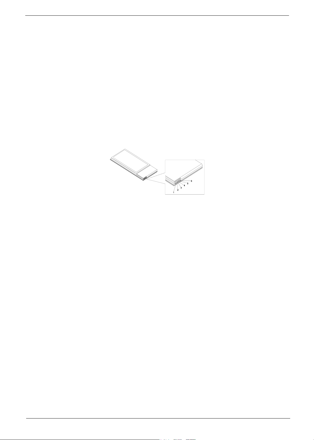
Check the Battery Pack
To check the battery pack, do the following:
From Software:
1. Check out the Power Management in control Panel
2. In Power Meter, confirm that if the parameters shown in the screen for Current Power Source and Total
Battery Power Remaining are correct.
3. Repeat the steps 1 and 2, for both battery and adapter.
4. This helps you identify first the problem is on recharging or discharging.
From Hardware:
1. Power off the computer.
2. Remove the battery pack and measure the voltage between battery terminals 1(+) and 6(ground). See the
following figure
3. If the voltage is still less than 7.5 Vdc after recharging, replace the battery.
To check the battery charge operation, use a discharged battery pack or a battery pack that has less than 50%
of the total power remaining when installed in the computer.
If the battery status indicator does not light up, remove the battery pack and let it return to room temperature.
Re-install the battery pack.
If the charge indicator still does not light up, replace the battery pack. If the charge indicator still does not light
up, replace the DC/DC charger board.
Touchpad Check
If the touchpad doesn’t work, do the following actions one at a time to correct the problem. Do not replace a
non-defective FRU:
1. Reconnect the touchpad cables.
2. Replace the touchpad.
3. Replace the system board.
After you use the touchpad, the pointer drifts on the screen for a short time. This self-acting pointer movement
can occur when a slight, steady pressure is applied to the touchpad pointer. This symptom is not a hardware
problem. No service actions are necessary if the pointer movement stops in a short period of time.
Chapter 4 76
Page 6

Power-On Self-Test (POST) Error Message
The POST error message index lists the error message and their possible causes. The most likely cause is
listed first.
NOTE: Perform the FRU replacement or actions in the sequence shown in FRU/Action column, if the FRU
replacement does not solve the problem, put the original part back in the computer. Do not replace a
non-defective FRU.
This index can also help you determine the next possible FRU to be replaced when servicing a computer.
If the symptom is not listed, see “Undetermined Problems” on page 89.
The following lists the error messages that the BIOS displays on the screen and the error symptoms classified
by function.
NOTE: Most of the error messages occur during POST. Some of them display information about a hardware
device, e.g., the amount of memory installed. Others may indicate a problem with a device, such as the
way it has been configured.
NOTE: If the system fails after you make changes in the BIOS Setup Utility menus, reset the computer, enter
Setup and install Setup defaults or correct the error.
77 Chapter 4
Page 7
Index of Error Messages
Error Code List
Error Codes Error Messages
006 Equipment Configuration Error
Causes:
1. CPU BIOS Update Code Mismatch
2. IDE Primary Channel Master Drive Error
(THe causes will be shown before “Equipment Configuration
Error”)
010 Memory Error at xxxx:xxxx:xxxxh (R:xxxxh, W:xxxxh)
070 Real Time Clock Error
071 CMOS Battery Bad
072 CMOS Checksum Error
110 System disabled.
Incorrect password is specified.
<No error code> Battery critical LOW
In this situation BIOS will issue 4 short beeps then shut down
system, no message will show.
<No error code> Thermal critical High
In this situation BIOS will shut down system, not show message.
Error Message List
Error Messages FRU/Action in Sequence
Failure Fixed Disk Reconnect hard disk drive connector.
“Load Default Settings” in BIOS Setup Utility.
Hard disk drive
System board
Stuck Key see “Keyboard or Auxiliary Input Device Check” on page 73.
Keyboard error see “Keyboard or Auxiliary Input Device Check” on page 73.
Keyboard Controller Failed see “Keyboard or Auxiliary Input Device Check” on page 73.
Keyboard locked - Unlock key switch Unlock external keyboard
Monitor type does not match CMOS - Run Setup Run “Load Default Settings” in BIOS Setup Utility.
Shadow RAM Failed at offset: nnnn BIOS ROM
System board
System RAM Failed at offset: nnnn DIMM
System board
Extended RAM Failed at offset: nnnn DIMM
System board
System battery is dead - Replace and run Setup Replace RTC battery and Run BIOS Setup Utility to reconfigure
System CMOS checksum bad - Default
configuration used
System timer error RTC battery
system time, then reboot system.
RTC battery
Run BIOS Setup Utility to reconfigure system time, then reboot
system.
Run BIOS Setup Utility to reconfigure system time, then reboot
system.
System board
Chapter 4 78
Page 8
Error Message List
Error Messages FRU/Action in Sequence
Real time clock error RTC battery
Run BIOS Setup Utility to reconfigure system time, then reboot
system.
System board
Previous boot incomplete - Default configuration
used
Memory size found by POST differed from
CMOS
Diskette drive A error Check the drive is defined with the proper diskette type in BIOS
Incorrect Drive A type - run SETUP Check the drive is defined with the proper diskette type in BIOS
System cache error - Cache disabled System board
CPU ID: System board
DMA Test Failed DIMM
Software NMI Failed DIMM
Fail-Safe Timer NMI Failed DIMM
Device Address Conflict Run “Load Default Settings” in BIOS Setup Utility.
Allocation Error for device Run “Load Default Settings” in BIOS Setup Utility.
Failing Bits: nnnn DIMM
Fixed Disk n None
Invalid System Configuration Data BIOS ROM
I/O device IRQ conflict Run “Load Default Settings” in BIOS Setup Utility.
Operating system not found Enter Setup and see if fixed disk and drive A: are properly identified.
Run “Load Default Settings” in BIOS Setup Utility.
RTC battery
System board
Run “Load Default Settings” in BIOS Setup Utility.
DIMM
System board
Setup Utility
See “External Diskette Drive Check” on page 73.
Setup Utility
System board
System board
System board
RTC battery
System board
RTC battery
System board
BIOS ROM
System board
System board
RTC battery
System board
Diskette drive
Hard disk drive
System board
79 Chapter 4
Page 9

Error Message List
No beep Error Messages FRU/Action in Sequence
No beep, power-on indicator turns off and LCD is
blank.
No beep, power-on indicator turns on and LCD is
blank.
No beep, power-on indicator turns on and LCD is
blank. But you can see POST on an external
CRT.
No beep, power-on indicator turns on and a
blinking cursor shown on LCD during POST.
No beep during POST but system runs correctly. Speaker
Power source (battery pack and power adapter). See “Power
System Check” on page 73.
Ensure every connector is connected tightly and correctly.
Reconnect the DIMM.
LED board.
System board.
Power source (battery pack and power adapter). See “Power
System Check” on page 73.
Reconnect the LCD connector
Hard disk drive
LCD inverter ID
LCD cable
LCD Inverter
LCD
System board
Reconnect the LCD connectors.
LCD inverter ID
LCD cable
LCD inverter
LCD
System board
Ensure every connector is connected tightly and correctly.
System board
System board
Chapter 4 80
Page 10

POST Code
Code Beeps POST Routine Description
02h Verify Real Mode
03h Disable Non-Maskable Interrupt (NMI)
04h Get CPU type
06h Initialize system hardware
08h Initialize chipset with initial POST values
09h Set IN POST flag
0Ah Initialize CPU registers
0Bh Enable CPU cache
0Ch Initialize caches to initial POST values
0Eh Initialize I/O component
0Fh Initialize the local bus IDE
10h Initialize Power Management
11h Load alternate registers with initial POST
values
12h Restore CPU control word during warm boot
13h Initialize PCI Bus Mastering devices
14h Initialize keyboard controller
16h 1-2-2-3 BIOS ROM checksum
17h Initialize cache before memory autosize
18h 8254 timer initialization
1Ah 8237 DMA controller initialization
1Ch Reset Programmable Interrupt Controller
20h 1-3-1-1 Test DRAM refresh
22h 1-3-1-3 Test 8742 Keyboard Controller
24h Set ES segment register to 4 GB
26h Enable A20 line
28h Autosize DRAM
29h Initialize POST Memory Manager
2Ah Clear 215 KB base RAM
2Ch 1-3-4-1 RAM failure on address line xxxx
2Eh 1-3-4-3 RAM failure on data bits xxxx of low byte of
2Fh Enable cache before system BIOS shadow
30h 1-4-1-1 RAM failure on data bits xxxx of high byte of
32h Test CPU bus-clock frequency
33h Initialize Phoenix Dispatch Manager
36h Warm start shut down
38h Shadow system BIOS ROM
3Ah Autosize cache
3Ch Advanced configuration of chipset registers
3Dh Load alternate registers with CMOS values
42h Initialize interrupt vectors
45h POST device initialization
memory bus
memory bus
81 Chapter 4
Page 11

Code Beeps POST Routine Description
46h 2-1-2-3 Check ROM copyright notice
48h Check video configuration against CMOS
49h Initialize PCI bus and devices
4Ah Initialize all video adapters in system
4Bh QuietBoot start (optional)
4Ch Shadow video BIOS ROM
4Eh Display BIOS copyright notice
50h Display CPU type and speed
51h Initialize EISA board
52h Test keyboard
54h Set key click if enabled
58h 2-2-3-1 Test for unexpected interrupts
59h Initialize POST display service
5Ah Display prompt “Press F2 to enter SETUP”
5Bh Disable CPU cache
5Ch Test RAM between 512 and 640 KB
60h Test extended memory
62h Test extended memory address lines
64h Jump to User Patch1
66h Configure advanced cache registers
67h Initialize Multi Processor APIC
68h Enable external and CPU caches
69h Setup System Management Mode (SMM) area
6Ah Display external L2 cache size
6Bh Load custom defaults (optional)
6Ch Display shadow-area message
6Eh Display possible high address for UMB
recovery
70h Display error messages
72h Check for configuration errors
76h Check for keyboard errors
7Ch Set up hardware interrupt vectors
7Eh Initialize coprocessor if present
80h Disable onboard Super I/O ports and IRQs
81h Late POST device initialization
82h Detect and install external RS232 ports
83h Configure non-MCD IDE controllers
84h Detect and install external parallel ports
85h Initialize PC-compatible PnP ISA devices
86h Re-initialize onboard I/O ports
87h Configure Motherboard Configurable Devices
(optional)
88h Initialize BIOS Area
89h Enable Non-Maskable Interrupts (NMIs)
8Ah Initialize Extended BIOS Data Area
8Bh Test and initialize PS/2 mouse
Chapter 4 82
Page 12

Code Beeps POST Routine Description
8Ch Initialize floppy controller
8Fh Determine number of ATA drives (optional)
90h Initialize hard-disk controllers
91h Initialize local-bus hard-disk controllers
92h Jump to UserPatch2
93h Build MPTABLE for multi-processor boards
95h Install CD ROM for boot
96h Clear huge ES segment register
97h Fixup Multi Processor table
98h 1-2 Search for option ROMs. One long, two short
beeps on checksum failure.
99h Check for SMART drive (optional)
9Ah Shadow option ROMs
9Ch Set up Power Management
9Dh Initialize security engine (optional)
9Eh Enable hardware interrupts
9Fh Determine number of ATA and SCSI drives
A0h Set time of day
A2h Check key lock
A4h Initialize Typematic rate
A8h Erase F2 prompt
AAh Scan for F2 key stroke
ACh Enter SETUP
AEh Clear Boot flag
B0h Check for errors
B2h POST done- prepare to boot operating system
B4h 1 One short beep before boot
B5h Terminate QuietBoot (optional)
B6h Check password (optional)
B9h Prepare Boot
BAh Initialize DMI parameters
BBh Initialize PnP Option ROMs
BCh Clear parity checkers
BDh Display MultiBoot menu
BEh Clear screen (optional)
BFh Check virus and backup reminders
C0h Try to boot with INT 19
C1h Initialize POST Error Manager (PEM)
C2h Initialize error logging
C3h Initialize error display function
C4h Initialize system error handler
C5h PnPnd dual CMOS (optional)
C6h Initialize notebook docking (optional)
C7h Initialize notebook docking late
C8h Force check (optional)
C9h Extended checksum (optional)
83 Chapter 4
Page 13

Code Beeps POST Routine Description
D2h Unknown interrupt
Code Beeps For Boot Block in Flash ROM
E0h Initialize the chipset
E1h Initialize the bridge
E2h Initialize the CPU
E3h Initialize the system timer
E4h Initialize system I/O
E5h Check force recovery boot
E6h Checksum BIOS ROM
E7h Go to BIOS
E8h Set Huge Segment
E9h Initialize Multi Processor
EAh Initialize OEM special code
EBh Initialize PIC and DMA
ECh Initialize Memory type
EDh Initialize Memory size
EEh Shadow Boot Block
EFh System memory test
F0h Initialize interrupt vectors
F1h Initialize Run Time Clock
F2h Initialize video
F3h Initialize System Management Mode
F4h 1 Output one beep before boot
F5h Boot to Mini DOS
F6h Clear Huge Segment
F7h Boot to Full DOS
Chapter 4 84
Page 14

Index of Symptom-to-FRU Error Message
LCD-Related Symptoms
Symptom / Error Action in Sequence
LCD backlight doesn't work
LCD is too dark
LCD brightness cannot be adjusted
LCD contrast cannot be adjusted
Unreadable LCD screen
Missing pels in characters
Abnormal screen
Wrong color displayed
LCD has extra horizontal or vertical lines
displayed.
Enter BIOS Utility to execute “Load Setup Default Settings”, then
reboot system.
Reconnect the LCD connectors.
Keyboard (if contrast and brightness function key doesn't work).
LCD inverter ID
LCD cable
LCD inverter
LCD
System board
Reconnect the LCD connector
LCD inverter ID
LCD cable
LCD inverter
LCD
System board
LCD inverter ID
LCD inverter
LCD cable
LCD
System board
Indicator-Related Symptoms
Symptom / Error Action in Sequence
Indicator incorrectly remains off or on, but system
runs correctly
Reconnect the inverter board
Inverter board
System board
Power-Related Symptoms
Symptom / Error Action in Sequence
Power shuts down during operation Power source (battery pack and power adapter). See “Power
The system doesn’t power-on. Power source (battery pack and power adapter). See “Power
The system doesn’t power-off. Power source (battery pack and power adapter). See “Power
System Check” on page 73.
Battery pack
Power adapter
Hard drive & battery connection board
System board
System Check” on page 73.
Battery pack
Power adapter
Hard drive & battery connection board
System board
System Check” on page 73.
Hold and press the power switch for more than 4 seconds.
System board
85 Chapter 4
Page 15

Power-Related Symptoms
Symptom / Error Action in Sequence
Battery can’t be charged See “Check the Battery Pack” on page 76.
Battery pack
System board
PCMCIA-Related Symptoms
Symptom / Error Action in Sequence
System cannot detect the PC Card (PCMCIA) PCMCIA slot assembly
System board
PCMCIA slot pin is damaged. PCMCIA slot assembly
Memory-Related Symptoms
Symptom / Error Action in Sequence
Memory count (size) appears different from
actual size.
Enter BIOS Setup Utility to execute “Load Default Settings, then
reboot system.
DIMM
System board
Speaker-Related Symptoms
Symptom / Error Action in Sequence
In Windows, multimedia programs, no sound
comes from the computer.
Internal speakers make noise or emit no sound. Speaker
Audio driver
Speaker
System board
System board
Power Management-Related Symptoms
Symptom / Error Action in Sequence
The system will not enter hibernation Keyboard (if control is from the keyboard)
Hard disk drive
System board
The system doesn't enter hibernation mode and
four short beeps every minute.
The system doesn’t enter standby mode after
closing the LCD
The system doesn't resume from hibernation
mode.
The system doesn't resume from standby mode
after opening the LCD.
See “Hibernation Mode” on page 29.
and see if the computer enters hibernation mode.
Press Fn+
Touchpad
Keyboard
Hard disk connection board
Hard disk drive
System board
See “Hibernation Mode” on page 29.
LCD cover switch
System board
See “Hibernation Mode” on page 29.
Hard disk connection board
Hard disk drive
System board
See “Hibernation Mode” on page 29.
LCD cover switch
System board
o
Chapter 4 86
Page 16

Power Management-Related Symptoms
Symptom / Error Action in Sequence
Battery fuel gauge in Windows doesn’t go higher
than 90%.
System hangs intermittently. Reconnect hard disk/CD-ROM drives.
Remove battery pack and let it cool for 2 hours.
Refresh battery (continue use battery until power off, then charge
battery).
Battery pack
System board
Hard disk connection board
System board
Peripheral-Related Symptoms
Symptom / Error Action in Sequence
System configuration does not match the
installed devices.
External display does not work correctly. Press Fn+F5, LCD/CRT/Both display switching
USB does not work correctly System board
Print problems. Ensure the “Parallel Port” in the “Onboard Devices Configuration” of
Serial or parallel port device problems. Ensure the “Serial Port” in the Devices Configuration” of BIOS Setup
Enter BIOS Setup Utility to execute “Load Default Settings”, then
reboot system.
Reconnect hard disk/CD-ROM/diskette drives.
System board
BIOS Setup Utility is set to Enabled.
Onboard Devices Configuration
Run printer self-test.
Printer driver
Printer cable
Printer
System Board
Utility is set to Enabled.
Device driver
Device cable
Device
System board
Keyboard/Touchpad-Related Symptoms
Symptom / Error Action in Sequence
Keyboard (one or more keys) does not work. Reconnect the keyboard cable.
Keyboard
System board
Touchpad does not work. Reconnect touchpad cable.
Touchpad board
System board
Modem-Related Symptoms
Symptom / Error Action in Sequence
Internal modem does not work correctly. Modem phone port
modem combo board
System board
NOTE: If you cannot find a symptom or an error in this list and the problem remains, see “Undetermined
Problems” on page 89.
87 Chapter 4
Page 17

Intermittent Problems
Intermittent system hang problems can be caused by a variety of reasons that have nothing to do with a
hardware defect, such as: cosmic radiation, electrostatic discharge, or software errors. FRU replacement
should be considered only when a recurring problem exists.
When analyzing an intermittent problem, do the following:
1. Run the advanced diagnostic test for the system board in loop mode at least 10 times.
2. If no error is detected, do not replace any FRU.
3. If any error is detected, replace the FRU. Rerun the test to verify that there are no more errors.
Chapter 4 88
Page 18

Undetermined Problems
The diagnostic problems does not identify which adapter or device failed, which installed devices are incorrect,
whether a short circuit is suspected, or whether the system is inoperative.
Follow these procedures to isolate the failing FRU (do not isolate non-defective FRU).
NOTE: Verify that all attached devices are supported by the computer.
NOTE: Verify that the power supply being used at the time of the failure is operating correctly. (See “Power
System Check” on page 73):
1. Power-off the computer.
2. Visually check them for damage. If any problems are found, replace the FRU.
3. Remove or disconnect all of the following devices:
q
Non-Acer devices
q
Printer, mouse, and other external devices
q
Battery pack
q
Hard disk drive
q
DIMM
q
CD-ROM/Diskette drive Module
q
PC Cards
4. Power-on the computer.
5. Determine if the problem has changed.
6. If the problem does not recur, reconnect the removed devices one at a time until you find the failing FRU.
7. If the problem remains, replace the following FRU one at a time. Do not replace a non-defective FRU:
q
System board
q
LCD assembly
89 Chapter 4
Page 19

How to Build NAPP Master Hard Disc Drive
CD to Disk Recovery
1. Prepare NAPP CD, Recovery CD and System CD.
2. Put NAPP CD into the optical drive. Then boot up the system.
3. The system will ask you if you want to build NAPP Master HDD. Please press any key to continue.
4. NAPP CD will start to preload the system, please click [Y].
5. Select CD to Disk Revocery.
Chapter 4 90
Page 20

6. Put the Recovery CD to the optical drive. This step is to create image files to the system, you do not have
to put the Recovery CD to the optical drive in order. Place one Recovery CD to the drive at one time till
you finish all Recovery CDs.
After you place the Recovery CD to the optical drive, you will see the display below.
91 Chapter 4
Page 21

7. Then insert the System CD to the optical drive.
8. You will see the screen displaying “PASS” when the system has buit NAPP Master hard disc drive.
Chapter 4 92
Page 22

Disk to Disk Recovery
1. Prepare NAPP CD, Recovery CD and System CD.
2. Put NAPP CD into the optical drive. Then boot up the system.
3. The system will ask you if you want to build NAPP Master HDD. Please press any key to continue.
4. NAPP CD will start to preload the system, please click [Y].
93 Chapter 4
Page 23

5. Select Disk to Disk Recovery. Then choose Single Language or Multi-Languages Recovery.
NOTE: For Multi-Languages Recovery, not more than five languages could be loaded to the system.
6. Put the Recovery CD to the optical drive. This step is to create image files to the system, you do not have
to put the Recovery CD to the optical drive in order. Place one Recovery CD to the drive at one time till
you finish all Recovery CDs.
Chapter 4 94
Page 24

After you place the Recovery CD to the optical drive, you will see the display below.
7. Then insert the System CD to the optical drive.
95 Chapter 4
Page 25

8. You will see the screen displaying “PASS” when the system has buit NAPP Master hard disc drive.
Chapter 4 96
Page 26

97 Chapter 4
 Loading...