

Page 1

Acer AS8950G
SERVICEGUIDE
Page 2

Revision History
Refer to the table below for the updates made to this AS8950G service guide.
Date Chapter Updates
Service guide files and updates are available on the ACER/CSD Website. For more
information, go to http://csd.acer.com.tw
.
Copyright
© 2010 by Acer Incorporated. All rights reserved. No part of this publication may be
reproduced, transmitted, transcribed, stored in a retrieval system, or translated into any
language or computer language, in any form or by any means, electronic, mechanical,
magnetic, optical, chemical, manual or otherwise, without the prior written permission of Acer
Incorporated.
Disclaimer
The information in this guide is subject to change without notice.
There are no representations or warranties, either expressed or implied, with respect to the
contents hereof and specifically disclaims any warranties of merchantability or fitness for any
particular purpose. The software described in this manual is sold or licensed "as is". Should
the programs prove defective following their purchase, the buyer (not the manufacturer,
distributor, or its dealer) assumes the entire cost of all necessary servicing, repair, and any
incidental or consequential damages resulting from any defect in the software.
Conventions
The following conventions are used in this manual:
!
WARNING:
!
CAUTION:
IMPORTANT:
+
The following typographical conventions are used in this document:
Book titles, directory names, file names, path names, and program/process names are shown in
italics.
ii
Indicates a potential for personal injury.
Indicates a potential loss of data or damage to equipment.
Indicates information that is important to know for the proper completion of a
procedure, choice of an option, or completing a task.
Example:
the DRS5 User's Guide
/usr/local/bin/fd
Page 3

the /TPH15spool_M program
Computer output (text that represents information displayed on a computer screen, such as
menus, prompts, responses to input, and error messages) are shown in constant width.
Example:
[01] The server has been stopped
User input (text that represents information entered by a computer user, such as command
names, option letters, and words) are shown in constant width bold.
Variables contained within user input are shown in angle brackets (< >).
Example:
At the prompt, type run <file name> -m
Keyboard keys are shown in bold italics.
Example:
After you enter the data, press Enter.
General information 0
Before using this information and the product it supports, read the following general
information.
This service guide provides you with all technical information relating to the basic configuration
for Acer’s global product offering. To better fit local market requirements and enhance product
competitiveness, your regional office may have decided to extend the functionality of a
machine (such as add-on cards, modems, or extra memory capabilities). These localized
features are not covered in this generic service guide. In such cases, contact your regional
offices or the responsible personnel/channel to provide you with further technical details.
When ordering FRU parts: Check the most up-to-date information available on your regional
Web or channel. If, for whatever reason, a part number change is made, it may not be noted
in this printed service guide.
Acer-authorized Service Providers: Your Acer office may have a different part number code
than those given in the FRU list in this service guide. You must use the list provided by your
regional Acer office to order FRU parts for repair and service of customer machines.
iii
Page 4

iv
Page 5

CHAPTER 1
Hardware Specifications
Features . . . . . . . . . . . . . . . . . . . . . . . . . . . . . . . . . . . . . . . . . . . . .1-5
Operating System . . . . . . . . . . . . . . . . . . . . . . . . . . . . . . . . . . .1-5
Platform . . . . . . . . . . . . . . . . . . . . . . . . . . . . . . . . . . . . . . . . . . .1-5
System Memory. . . . . . . . . . . . . . . . . . . . . . . . . . . . . . . . . . . . . 1-5
Display . . . . . . . . . . . . . . . . . . . . . . . . . . . . . . . . . . . . . . . . . . . .1-5
Storage Subsystem . . . . . . . . . . . . . . . . . . . . . . . . . . . . . . . . . .1-5
Audio Subsystem. . . . . . . . . . . . . . . . . . . . . . . . . . . . . . . . . . . .1-6
Graphics . . . . . . . . . . . . . . . . . . . . . . . . . . . . . . . . . . . . . . . . . .1-6
Privacy Control . . . . . . . . . . . . . . . . . . . . . . . . . . . . . . . . . . . . .1-6
Optical Media Drive . . . . . . . . . . . . . . . . . . . . . . . . . . . . . . . . . .1-7
Communication . . . . . . . . . . . . . . . . . . . . . . . . . . . . . . . . . . . . .1-7
Dimension and Weight. . . . . . . . . . . . . . . . . . . . . . . . . . . . . . . .1-8
Power Adapter and Battery . . . . . . . . . . . . . . . . . . . . . . . . . . . .1-8
I/O Ports. . . . . . . . . . . . . . . . . . . . . . . . . . . . . . . . . . . . . . . . . . .1-8
Special Keys and Controls. . . . . . . . . . . . . . . . . . . . . . . . . . . . .1-9
Environment. . . . . . . . . . . . . . . . . . . . . . . . . . . . . . . . . . . . . . . .1-9
Warranty . . . . . . . . . . . . . . . . . . . . . . . . . . . . . . . . . . . . . . . . . . 1-9
Optional Items . . . . . . . . . . . . . . . . . . . . . . . . . . . . . . . . . . . . . .1-10
Software. . . . . . . . . . . . . . . . . . . . . . . . . . . . . . . . . . . . . . . . . . .1-11
Notebook Tour . . . . . . . . . . . . . . . . . . . . . . . . . . . . . . . . . . . . . . .1-13
Top View . . . . . . . . . . . . . . . . . . . . . . . . . . . . . . . . . . . . . . . . . .1-13
Media Console. . . . . . . . . . . . . . . . . . . . . . . . . . . . . . . . . . . . . .1-16
Closed Front View . . . . . . . . . . . . . . . . . . . . . . . . . . . . . . . . . . .1-17
Rear View . . . . . . . . . . . . . . . . . . . . . . . . . . . . . . . . . . . . . . . . . 1-18
Left View . . . . . . . . . . . . . . . . . . . . . . . . . . . . . . . . . . . . . . . . . .1-19
Right View . . . . . . . . . . . . . . . . . . . . . . . . . . . . . . . . . . . . . . . . .1-21
Base View . . . . . . . . . . . . . . . . . . . . . . . . . . . . . . . . . . . . . . . . .1-22
Touchpad Basics . . . . . . . . . . . . . . . . . . . . . . . . . . . . . . . . . . . .1-23
Using the Keyboard . . . . . . . . . . . . . . . . . . . . . . . . . . . . . . . . . . 1-24
Windows Keys . . . . . . . . . . . . . . . . . . . . . . . . . . . . . . . . . . . . . . 1-25
Hot Keys . . . . . . . . . . . . . . . . . . . . . . . . . . . . . . . . . . . . . . . . . . 1-26
System Block Diagram . . . . . . . . . . . . . . . . . . . . . . . . . . . . . . .1-28
Specification Tables . . . . . . . . . . . . . . . . . . . . . . . . . . . . . . . . . . .1-29
Computer specifications . . . . . . . . . . . . . . . . . . . . . . . . . . . . . .1-29
Processor. . . . . . . . . . . . . . . . . . . . . . . . . . . . . . . . . . . . . . . . . .1
Processor Specifications . . . . . . . . . . . . . . . . . . . . . . . . . . . . . .1-31
CPU Fan True Value Table (TJ100-CPU) . . . . . . . . . . . . . . . . . 1-31
System Memory. . . . . . . . . . . . . . . . . . . . . . . . . . . . . . . . . . . . . 1-31
Memory Combinations. . . . . . . . . . . . . . . . . . . . . . . . . . . . . . . .1-32
Video Interface. . . . . . . . . . . . . . . . . . . . . . . . . . . . . . . . . . . . . .1-33
BIOS . . . . . . . . . . . . . . . . . . . . . . . . . . . . . . . . . . . . . . . . . . . . . 1-33
-30
v
Page 6

LAN Interface. . . . . . . . . . . . . . . . . . . . . . . . . . . . . . . . . . . . . . .1-34
Keyboard . . . . . . . . . . . . . . . . . . . . . . . . . . . . . . . . . . . . . . . . . .1-34
Hard Disk Drive (AVL components). . . . . . . . . . . . . . . . . . . . . .1-35
Super-Multi Drive. . . . . . . . . . . . . . . . . . . . . . . . . . . . . . . . . . . .1-38
BD Drive . . . . . . . . . . . . . . . . . . . . . . . . . . . . . . . . . . . . . . . . . .1-43
LED 18.4”. . . . . . . . . . . . . . . . . . . . . . . . . . . . . . . . . . . . . . . . . .1-46
LCD Inverter (not available with this model) . . . . . . . . . . . . . . .1-46
Display Supported Resolution (LCD Supported Resolution) . . .1-47
Display Supported Resolution (GPU Supported Resolution). . .1-47
Mini Card . . . . . . . . . . . . . . . . . . . . . . . . . . . . . . . . . . . . . . . . . .1-49
3G Card (not available in this model) . . . . . . . . . . . . . . . . . . . . 1-49
Audio Codec and Amplifier . . . . . . . . . . . . . . . . . . . . . . . . . . . .1-50
Audio Interface. . . . . . . . . . . . . . . . . . . . . . . . . . . . . . . . . . . . . .1-51
Battery . . . . . . . . . . . . . . . . . . . . . . . . . . . . . . . . . . . . . . . . . . . . 1-52
VRAM . . . . . . . . . . . . . . . . . . . . . . . . . . . . . . . . . . . . . . . . . . . .1-52
USB Port . . . . . . . . . . . . . . . . . . . . . . . . . . . . . . . . . . . . . . . . . .1-52
AC Adapter . . . . . . . . . . . . . . . . . . . . . . . . . . . . . . . . . . . . . . . . 1-53
System Power Management . . . . . . . . . . . . . . . . . . . . . . . . . . .1-53
Card Reader . . . . . . . . . . . . . . . . . . . . . . . . . . . . . . . . . . . . . . . 1-53
System LED Indicator . . . . . . . . . . . . . . . . . . . . . . . . . . . . . . . .1-55
System DMA Specification . . . . . . . . . . . . . . . . . . . . . . . . . . . .1-55
System Interrupt Specification. . . . . . . . . . . . . . . . . . . . . . . . . .1-56
CHAPTER 2
System Utilities
BIOS Setup Utility . . . . . . . . . . . . . . . . . . . . . . . . . . . . . . . . . . . . .2-3
Navigating the BIOS Utility . . . . . . . . . . . . . . . . . . . . . . . . . . . .2-3
BIOS . . . . . . . . . . . . . . . . . . . . . . . . . . . . . . . . . . . . . . . . . . . . . . . .2-4
Information. . . . . . . . . . . . . . . . . . . . . . . . . . . . . . . . . . . . . . . . .2-4
Main. . . . . . . . . . . . . . . . . . . . . . . . . . . . . . . . . . . . . . . . . . . . . . 2-6
Security . . . . . . . . . . . . . . . . . . . . . . . . . . . . . . . . . . . . . . . . . . .2-8
Boot . . . . . . . . . . . . . . . . . . . . . . . . . . . . . . . . . . . . . . . . . . . . . .2-12
Exit. . . . . . . . . . . . . . . . . . . . . . . . . . . . . . . . . . . . . . . . . . . . . . .2-13
BIOS Flash Utilities. . . . . . . . . . . . . . . . . . . . . . . . . . . . . . . . . . . .2-14
DOS Flash Utility . . . . . . . . . . . . . . . . . . . . . . . . . . . . . . . . . . . .2-15
WinFlash Utility . . . . . . . . . . . . . . . . . . . . . . . . . . . . . . . . . . . . .2-17
Remove HDD/BIOS Password Utilities . . . . . . . . . . . . . . . . . . . .2-18
Removing BIOS Passwords . . . . . . . . . . . . . . . . . . . . . . . . . . .2-20
Miscellaneous Tools . . . . . . . . . . . . . . . . . . . . . . . . . . . . . . . . . 2-21
vi
Page 7

CHAPTER 3
Machine Maintenance Procedures
Introduction . . . . . . . . . . . . . . . . . . . . . . . . . . . . . . . . . . . . . . . . . .3-5
General Information . . . . . . . . . . . . . . . . . . . . . . . . . . . . . . . . . . .3-5
Tools . . . . . . . . . . . . . . . . . . . . . . . . . . . . . . . . . . . . . . . . . . . . . . .3-5
Screw Table . . . . . . . . . . . . . . . . . . . . . . . . . . . . . . . . . . . . . . . . . .3-6
Maintenance Flowchart . . . . . . . . . . . . . . . . . . . . . . . . . . . . . . . .3-7
Getting Started . . . . . . . . . . . . . . . . . . . . . . . . . . . . . . . . . . . . . . .3-8
Battery Pack Removal . . . . . . . . . . . . . . . . . . . . . . . . . . . . . . . . 3-9
Battery Pack Installation . . . . . . . . . . . . . . . . . . . . . . . . . . . . . .3-9
Dummy Card Removal . . . . . . . . . . . . . . . . . . . . . . . . . . . . . . .3-10
Dummy Card Installation . . . . . . . . . . . . . . . . . . . . . . . . . . . . . .3-10
Base Door Removal. . . . . . . . . . . . . . . . . . . . . . . . . . . . . . . . . .3-11
Base Door Installation . . . . . . . . . . . . . . . . . . . . . . . . . . . . . . . .3-11
HDD (Hard Disk Drive) Module Removal . . . . . . . . . . . . . . . . .3-12
HDD Module Installation . . . . . . . . . . . . . . . . . . . . . . . . . . . . . .3-13
DIMM (Dual In-line Memory Module) Module Removal. . . . . . .3-14
DIMM Module Installation . . . . . . . . . . . . . . . . . . . . . . . . . . . . .3-14
WLAN (Wireless Local Area Network) Module Removal. . . . . .3-15
WLAN Module Installation . . . . . . . . . . . . . . . . . . . . . . . . . . . . .3-15
Slave HDD Door Removal . . . . . . . . . . . . . . . . . . . . . . . . . . . . .3-16
Slave HDD Door Installation . . . . . . . . . . . . . . . . . . . . . . . . . . .3-16
Slave HDD Module Removal . . . . . . . . . . . . . . . . . . . . . . . . . . .3-17
Slave HDD Module Installation . . . . . . . . . . . . . . . . . . . . . . . . .3-17
ODD (Optical Disk Drive) Module Removal. . . . . . . . . . . . . . . .3-18
ODD Module Installation . . . . . . . . . . . . . . . . . . . . . . . . . . . . . .3-19
Keyboard Removal . . . . . . . . . . . . . . . . . . . . . . . . . . . . . . . . . . 3-20
Keyboard Installation . . . . . . . . . . . . . . . . . . . . . . . . . . . . . . . . . 3-22
LCD (Liquid Crystal Display) Module Removal . . . . . . . . . . . . .3-24
LCD Module Installation. . . . . . . . . . . . . . . . . . . . . . . . . . . . . . .3-26
Upper Cover Removal . . . . . . . . . . . . . . . . . . . . . . . . . . . . . . . .3-27
Upper Cover Installation . . . . . . . . . . . . . . . . . . . . . . . . . . . . . .3-28
Microphone Module Removal . . . . . . . . . . . . . . . . . . . . . . . . . .3-29
Microphone Module Installation . . . . . . . . . . . . . . . . . . . . . . . . .3-30
Bluetooth Module Removal . . . . . . . . . . . . . . . . . . . . . . . . . . . .3-31
Bluetooth Module Installation. . . . . . . . . . . . . . . . . . . . . . . . . . .3-31
Touchpad Board Removal . . . . . . . . . . . . . . . . . . . . . . . . . . . . .3
Touchpad Board Installation . . . . . . . . . . . . . . . . . . . . . . . . . . .3-33
Fingerprint Module Removal . . . . . . . . . . . . . . . . . . . . . . . . . . .3-34
-32
vii
Page 8

Finger Print Module Installation . . . . . . . . . . . . . . . . . . . . . . . . .3-34
LAN Module Removal . . . . . . . . . . . . . . . . . . . . . . . . . . . . . . . .3-35
LAN Module Installation. . . . . . . . . . . . . . . . . . . . . . . . . . . . . . .3-36
USB Module Removal . . . . . . . . . . . . . . . . . . . . . . . . . . . . . . . .3-37
USB Module Installation . . . . . . . . . . . . . . . . . . . . . . . . . . . . . .3-37
Mainboard Removal. . . . . . . . . . . . . . . . . . . . . . . . . . . . . . . . . .3-38
Mainboard Installation . . . . . . . . . . . . . . . . . . . . . . . . . . . . . . . .3-40
Speaker and Subwoofer Assembly Removal . . . . . . . . . . . . . .3-41
Speaker and Subwoofer Assembly Installation . . . . . . . . . . . . .3-41
RTC Battery Removal . . . . . . . . . . . . . . . . . . . . . . . . . . . . . . . .3-42
RTC Battery Installation. . . . . . . . . . . . . . . . . . . . . . . . . . . . . . .3-43
Thermal Module Removal . . . . . . . . . . . . . . . . . . . . . . . . . . . . .3-44
Thermal Module Installation. . . . . . . . . . . . . . . . . . . . . . . . . . . .3-45
CPU Removal . . . . . . . . . . . . . . . . . . . . . . . . . . . . . . . . . . . . . .3-47
CPU Installation. . . . . . . . . . . . . . . . . . . . . . . . . . . . . . . . . . . . .3-47
PCH Heatsink Removal . . . . . . . . . . . . . . . . . . . . . . . . . . . . . . .3-48
PCH Heatsink Installation . . . . . . . . . . . . . . . . . . . . . . . . . . . . .3-49
LCD Module Removal and Installation Instructions . . . . . . . . . .3-50
CHAPTER 4
Troubleshooting
Introduction . . . . . . . . . . . . . . . . . . . . . . . . . . . . . . . . . . . . . . . . . .4-3
General Information . . . . . . . . . . . . . . . . . . . . . . . . . . . . . . . . . . .4-3
Power On Issues . . . . . . . . . . . . . . . . . . . . . . . . . . . . . . . . . . . .4-4
No Display Issues . . . . . . . . . . . . . . . . . . . . . . . . . . . . . . . . . . .4-5
LCD Failure . . . . . . . . . . . . . . . . . . . . . . . . . . . . . . . . . . . . . . . .4-7
Keyboard Failure . . . . . . . . . . . . . . . . . . . . . . . . . . . . . . . . . . . .4-8
Touchpad Failure. . . . . . . . . . . . . . . . . . . . . . . . . . . . . . . . . . . .4-9
Internal Speaker Failure . . . . . . . . . . . . . . . . . . . . . . . . . . . . . .4-10
Microphone Failure . . . . . . . . . . . . . . . . . . . . . . . . . . . . . . . . . .4-12
USB Failure . . . . . . . . . . . . . . . . . . . . . . . . . . . . . . . . . . . . . . . .4-13
Other Functions Failure . . . . . . . . . . . . . . . . . . . . . . . . . . . . . . .4-14
Intermittent Problems. . . . . . . . . . . . . . . . . . . . . . . . . . . . . . . . . .4-15
Undetermined Problems . . . . . . . . . . . . . . . . . . . . . . . . . . . . . . .4-15
Post Codes . . . . . . . . . . . . . . . . . . . . . . . . . . . . . . . . . . . . . . . . . .4-16
viii
Page 9

CHAPTER 5
Jumper and Connector Locations
Mainboard Jumper and Connector Locations . . . . . . . . . . . . . .5-3
Clearing Password Check and BIOS Recovery . . . . . . . . . . . . .5-5
Clearing Password Check . . . . . . . . . . . . . . . . . . . . . . . . . . . . .5-5
Clear CMOS Jumper . . . . . . . . . . . . . . . . . . . . . . . . . . . . . . . . .5-6
BIOS Recovery by Crisis Disk . . . . . . . . . . . . . . . . . . . . . . . . . . 5-6
CHAPTER 6
FRU (Field Replaceable Unit) List
Exploded Diagrams . . . . . . . . . . . . . . . . . . . . . . . . . . . . . . . . . . .6-4
FRU List . . . . . . . . . . . . . . . . . . . . . . . . . . . . . . . . . . . . . . . . . . . . .6-8
Screw List . . . . . . . . . . . . . . . . . . . . . . . . . . . . . . . . . . . . . . . . . . .6-19
CHAPTER 7
Model Definition and Configuration
AS8950G . . . . . . . . . . . . . . . . . . . . . . . . . . . . . . . . . . . . . . . . . . . .7-3
CHAPTER 8
Test Compatible Components
Microsoft® Windows® 7 Environment Test . . . . . . . . . . . . . . . . 8-4
CHAPTER 9
Online Support Information
Introduction . . . . . . . . . . . . . . . . . . . . . . . . . . . . . . . . . . . . . . . . . .9-3
ix
Page 10

x
Page 11

CHAPTER 1
Hardware Specifications
Page 12

Features . . . . . . . . . . . . . . . . . . . . . . . . . . . . . . . . . . . . . . . . . . . . . 1-5
Operating System . . . . . . . . . . . . . . . . . . . . . . . . . . . . . . . . . . .1-5
Platform . . . . . . . . . . . . . . . . . . . . . . . . . . . . . . . . . . . . . . . . . . .1-5
System Memory. . . . . . . . . . . . . . . . . . . . . . . . . . . . . . . . . . . . . 1-5
Display . . . . . . . . . . . . . . . . . . . . . . . . . . . . . . . . . . . . . . . . . . . .1-5
Storage Subsystem . . . . . . . . . . . . . . . . . . . . . . . . . . . . . . . . . .1-5
Audio Subsystem. . . . . . . . . . . . . . . . . . . . . . . . . . . . . . . . . . . .1-6
Graphics . . . . . . . . . . . . . . . . . . . . . . . . . . . . . . . . . . . . . . . . . .1-6
Privacy Control . . . . . . . . . . . . . . . . . . . . . . . . . . . . . . . . . . . . .1-6
Optical Media Drive . . . . . . . . . . . . . . . . . . . . . . . . . . . . . . . . . .1-7
Communication . . . . . . . . . . . . . . . . . . . . . . . . . . . . . . . . . . . . .1-7
Dimension and Weight. . . . . . . . . . . . . . . . . . . . . . . . . . . . . . . .1-8
Power Adapter and Battery . . . . . . . . . . . . . . . . . . . . . . . . . . . .1-8
I/O Ports. . . . . . . . . . . . . . . . . . . . . . . . . . . . . . . . . . . . . . . . . . .1-8
Special Keys and Controls. . . . . . . . . . . . . . . . . . . . . . . . . . . . .1-9
Environment. . . . . . . . . . . . . . . . . . . . . . . . . . . . . . . . . . . . . . . .1-9
Warranty . . . . . . . . . . . . . . . . . . . . . . . . . . . . . . . . . . . . . . . . . . 1-9
Optional Items . . . . . . . . . . . . . . . . . . . . . . . . . . . . . . . . . . . . . .1-10
Software. . . . . . . . . . . . . . . . . . . . . . . . . . . . . . . . . . . . . . . . . . .1-11
Notebook Tour. . . . . . . . . . . . . . . . . . . . . . . . . . . . . . . . . . . . . . . .1-13
Top View . . . . . . . . . . . . . . . . . . . . . . . . . . . . . . . . . . . . . . . . . .1-13
Media Console. . . . . . . . . . . . . . . . . . . . . . . . . . . . . . . . . . . . . .1-16
Closed Front View . . . . . . . . . . . . . . . . . . . . . . . . . . . . . . . . . . .1-17
Rear View . . . . . . . . . . . . . . . . . . . . . . . . . . . . . . . . . . . . . . . . . 1-18
Left View . . . . . . . . . . . . . . . . . . . . . . . . . . . . . . . . . . . . . . . . . .1-19
Right View . . . . . . . . . . . . . . . . . . . . . . . . . . . . . . . . . . . . . . . . .1-21
Base View . . . . . . . . . . . . . . . . . . . . . . . . . . . . . . . . . . . . . . . . .1-22
Touchpad Basics . . . . . . . . . . . . . . . . . . . . . . . . . . . . . . . . . . . .1-23
Using the Keyboard . . . . . . . . . . . . . . . . . . . . . . . . . . . . . . . . . . 1-24
Windows Keys . . . . . . . . . . . . . . . . . . . . . . . . . . . . . . . . . . . . . . 1-25
Hot Keys . . . . . . . . . . . . . . . . . . . . . . . . . . . . . . . . . . . . . . . . . . 1-26
System Block Diagram . . . . . . . . . . . . . . . . . . . . . . . . . . . . . . .1-28
Specification Tables . . . . . . . . . . . . . . . . . . . . . . . . . . . . . . . . . . .1-29
Computer specifications . . . . . . . . . . . . . . . . . . . . . . . . . . . . . .1-29
Processor. . . . . . . . . . . . . . . . . . . . . . . . . . . . . . . . . . . . . . . . . .1
-30
Processor Specifications . . . . . . . . . . . . . . . . . . . . . . . . . . . . . .1-31
CPU Fan True Value Table (TJ100-CPU) . . . . . . . . . . . . . . . . . 1-31
System Memory. . . . . . . . . . . . . . . . . . . . . . . . . . . . . . . . . . . . . 1-31
Memory Combinations. . . . . . . . . . . . . . . . . . . . . . . . . . . . . . . .1-32
Video Interface. . . . . . . . . . . . . . . . . . . . . . . . . . . . . . . . . . . . . .1-33
BIOS . . . . . . . . . . . . . . . . . . . . . . . . . . . . . . . . . . . . . . . . . . . . . 1-33
LAN Interface. . . . . . . . . . . . . . . . . . . . . . . . . . . . . . . . . . . . . . .1-34
Keyboard . . . . . . . . . . . . . . . . . . . . . . . . . . . . . . . . . . . . . . . . . .1-34
Hard Disk Drive (AVL components). . . . . . . . . . . . . . . . . . . . . .1-35
Super-Multi Drive. . . . . . . . . . . . . . . . . . . . . . . . . . . . . . . . . . . .1-38
1-2
Page 13

BD Drive . . . . . . . . . . . . . . . . . . . . . . . . . . . . . . . . . . . . . . . . . .1-43
LED 18.4”. . . . . . . . . . . . . . . . . . . . . . . . . . . . . . . . . . . . . . . . . .1-46
LCD Inverter (not available with this model) . . . . . . . . . . . . . . .1-46
Display Supported Resolution (LCD Supported Resolution) . . .1-47
Display Supported Resolution (GPU Supported Resolution). . .1-47
Mini Card . . . . . . . . . . . . . . . . . . . . . . . . . . . . . . . . . . . . . . . . . .1-49
3G Card (not available in this model) . . . . . . . . . . . . . . . . . . . . 1-49
Audio Codec and Amplifier . . . . . . . . . . . . . . . . . . . . . . . . . . . .1-50
Audio Interface. . . . . . . . . . . . . . . . . . . . . . . . . . . . . . . . . . . . . .1-51
Battery . . . . . . . . . . . . . . . . . . . . . . . . . . . . . . . . . . . . . . . . . . . . 1-52
VRAM . . . . . . . . . . . . . . . . . . . . . . . . . . . . . . . . . . . . . . . . . . . .1-52
USB Port . . . . . . . . . . . . . . . . . . . . . . . . . . . . . . . . . . . . . . . . . .1-52
AC Adapter . . . . . . . . . . . . . . . . . . . . . . . . . . . . . . . . . . . . . . . . 1-53
System Power Management . . . . . . . . . . . . . . . . . . . . . . . . . . .1-53
Card Reader . . . . . . . . . . . . . . . . . . . . . . . . . . . . . . . . . . . . . . . 1-53
System LED Indicator . . . . . . . . . . . . . . . . . . . . . . . . . . . . . . . .1-55
System DMA Specification . . . . . . . . . . . . . . . . . . . . . . . . . . . .1-55
System Interrupt Specification. . . . . . . . . . . . . . . . . . . . . . . . . .1-56
1-3
Page 14

1-4
Page 15

Hardware Specifications and Configurations
Features 0
The following is a summary of the computer’s many features:
Operating System 0
Genuine Windows
Genuine Windows
®
7 Ultimate 64-bit
®
7 Home Premium 64-bit
Platform 0
®
Intel
i7-2630QM/i7-2720QM processor (6 MB L3 cache, 2/2.20 GHz with Turbo Boost up to 2.90/3.30
Mobile Intel
Core™ i7-2820QM processor (8 MB L3 cache, 2.30 GHz with Turbo Boost up to 3.40 GHz,
DDR3 1600 MHz, 45 W),
GHz, DDR3 1600 MHz, 45 W), supporting Intel
®
HM65 Express Chipset
®
64 architecture, Intel® Smart Cache
System Memory 0
Dual-channel DDR3 SDRAM support
Up to 4 GB of DDR3 system memory, upgradable to 16 GB using four soDIMM
modules
Display 0
18.4" Full HD 1920 x 1080 resolution, high-brightness (220-nit) Acer CineCrystal
TFT LCD
Mercury-free, environment-friendly
Frameless design
16:9 aspect ratio
™
LED-backlit
Storage Subsystem 0
Hard disk drive 0
One or two 160/250/320/500/640/750 GB or larger
Multi-in-1 card reader, supporting 0
Secure Digital
PRO), xD-Picture Card
Hardware Specifications and Configurations 1-5
™
(SD), MultiMediaCard™ (MMC), Memory Stick™ (MS), Memory Stick PRO™ (MS
™
(xD)
Page 16

Audio Subsystem 0
Optimized Dolby
®
Home Theater® v47 audio enhancement, featuring Audio Optimizer, Audio
Regulator, Volume Leveler, Volume Maximizer, Intelligent EQ, Dialogue Enhancer, Surround
Virtualizer for Headphones, Surround Virtualizer for Built-in Speakers, and Dolby
®
Digital Output
technologies
Acer CineSurround with five built-in speakers and the Acer Tuba CineBass subwoofer supporting
low-frequency effects
True 5.1-channel surround sound output
High-definition audio support
S/PDIF (Sony/Philips Digital Interface) support for digital speakers
MS-Sound compatible
Built-in digital microphone
Graphics 0
Dual independent display support
16.7 million colors
External resolution / refresh rates:
VGA port up to 2048 x 1536: 85 Hz
HDMI
MPEG-2/DVD decoding
VC-1 and H.264 (AVC) decoding
Microsoft
HDMI
Protection) support
®
port up to 1920 x 1080: 60 Hz
®
DirectX® Video Acceleration (DXVA) application interface (API)
®
(High-Definition Multimedia Interface) with HDCP (High-bandwidth Digital Content
AMD Radeon™ HD 6850M 0
AMD Radeon
Decoder 2 (UVD 2), OpenEXR High Dynamic-Range (HDR) technology, Shader Model 5.0,
Microsoft
™
HD 6850M with 2048 MB of dedicated DDR3 VRAM, supporting Unified Video
®
DirectX® 11, OpenGL® 3.1, OpenCL™ 1.1
AMD Radeon™ HD 6650M 0
AMD Radeon
Decoder 3 (UVD 3), OpenEXR High Dynamic-Range (HDR) technology, Shader Model 5.0,
Microsoft
MPEG-4 Part 2 DivX
™
HD 6650M with 1024 MB of dedicated DDR3 VRAM, supporting Unified Video
®
DirectX® 11, OpenGL® 3.1, OpenCL™ 1.1
®
and Xvid decoding
Privacy Control 0
Acer Bio-Protection fingerprint solution, featuring Pre-Boot Authentication (PBA), computer
protection, Acer FingerLaunch
BIOS user, supervisor, HDD passwords
Kensington lock slot
1-6 Hardware Specifications and Configurations
Page 17

Optical Media Drive 0
4X Blu-ray Disc
Read: 24X CD-ROM, 24X CD-R, 24X CD-RW, 8X DVD-ROM, 8X DVD-R, 8X
™
writer / DVD-Super Multi double-layer drive:
DVD+R, 6X DVD-ROM DL, 6X DVD-R DL, 6X DVD+R DL, 8X DVD-RW, 8X
DVD+RW, 5X DVD-RAM, 4X BD-ROM, 4X BD-R, 4X BD-RE, 4X BD-ROM DL, 4X
BD-R DL
Write: 24X CD-R, 10X CD-RW, 8X DVD-R, 8X DVD+R, 6X DVD-RW, 6X DVD+RW,
5X DVD-RAM, 4X DVD+R DL, 4X DVD-R DL, 4X BD-R, 2X BD-RE, 4X BD-R DL
4X Blu-ray Disc
Read: 24X CD-ROM, 24X CD-R, 16X CD-RW, 8X DVD-ROM, 8X DVD-R, 8X
™
/ DVD-Super Multi double-layer drive:
DVD+R, 4X DVD-ROM DL, 4X DVD-R DL, 4X DVD+R DL, 4X DVD-RW, 4X
DVD+RW, 5X DVD-RAM, 4X BD-ROM, 4X BD-R, 4X BD-RE, 4X BD-ROM DL, 4X
BD-R DL, 4X BD-RE DL
Write: 16X CD-R, 10X CD-RW, 8X DVD-R, 8X DVD+R, 4X DVD-RW, 4X DVD+RW,
5X DVD-RAM, 4X DVD+R DL, 4X DVD-R DL
8X DVD-Super Multi double-layer drive:
Read: 24X CD-ROM, 24X CD-R, 24X CD-RW, 8X DVD-ROM, 8X DVD-R, 8X
DVD+R, 6X DVD-ROM DL, 4X DVD-R DL, 4X DVD+R DL, 6X DVD-RW, 6X
DVD+RW, 5X DVD-RAM
Write: 24X CD-R, 16X CD-RW, 8X DVD-R, 8X DVD+R, 4X DVD-R DL, 4X DVD+R
DL, 6X DVD-RW, 8X DVD+RW, 5X DVD-RAM
Communication 0
Webcam 0
Acer Video Conference, featuring:
Acer Crystal Eye webcam with 1280 x 1024 resolution
Acer Video Conference Manager software, featuring Video Quality Enhancement
(VQE) technology, supporting 640 x 480 resolution online video calls
WLAN 0
Acer InviLink
Acer InviLink
Supporting Acer SignalUp
™
Nplify™ 802.11b/g/n Wi-Fi CERTIFIED
™
Nplify™ 802.11b/g Wi-Fi CERTIFIED
™
wireless technology
WPAN 0
Bluetooth
®
3.0+HS
LAN 0
Gigabit Ethernet, Wake-on-LAN ready
™
™
Hardware Specifications and Configurations 1-7
Page 18

Dimension and Weight 0
Dimensions 0
440 (W) x 295 (D) x 29.5/39.4 (H) mm (17.34 x 11.62 x 1.16/1.55 inches)
Weight 0
4.6 kg (10.1 lbs.)13 with 8-cell battery
Power Adapter and Battery 0
ACPI 3.0 CPU power management standard: supports Standby and Hibernation power-saving
modes
Power adapter 0
3-pin 120 W AC adapter:
155 (W) x 67 (D) x 36.5 (H) mm (6.1 x 2.63 x 1.43 inches)
570 g (1.25 lbs.)13 with 180 cm DC cable
Battery 0
83 Wh 6000 mAh 8-cell Li-ion standard battery pack
Battery life: 3 hours16
ENERGY STAR
®
I/O Ports 0
Multi-in-1 card reader (SD
Three USB 2.0 ports16
USB 3.0 port
IEEE 1394 port
eSATA / USB 2.0 port
HDMI
Consumer infrared (CIR) port
External display (VGA) port
Headphone/speaker/line-out jack with S/PDIF support
Microphone-in jack
Line-in jack
Ethernet (RJ-45) port
DC-in jack for AC adapter
®
port with HDCP support
™
, MMC, MS, MS PRO, xD)
1-8 Hardware Specifications and Configurations
Page 19

Special Keys and Controls 0
Keyboard 0
103-/104-/107-key back-mounted keyboard with independent standard numeric keypad,
international language support
Touchpad 0
Dual-mode touchpad with Media Console / multi-gesture function, supporting two-finger scroll,
pinch, rotate, flip
Media keys 0
Touch-sensitive Media Console, featuring:
Movie, music shortcuts
Media controls: play/pause, stop, previous, next
Horizontal volume wheel
Control keys 0
Instant-on Acer Arcade
Acer PowerSmart or programmable key
Acer Backup key
Communication key
Acer Bio-Protection fingerprint reader
™
Deluxe support
Environment 0
Temperature 0
Operating: 5 °C to 35 °C
Non-operating: -20 °C to 65 °C
Humidity (non-condensing) 0
Operating: 20% to 80%
Non-operating: 20% to 80%
Warranty 0
One-year International Travelers Warranty (ITW)
Hardware Specifications and Configurations 1-9
Page 20

Optional Items 0
Acer Xpress VoIP phone and Acer Video Conference Manager pack
Acer Media Center remote control
1 GB / 2 GB / 4 GB DDR3 1066 MHz soDIMM module
160/250/320/500/640/750 GB hard disk drive
8-cell Li-ion battery pack
3-pin 120 W AC adapter
External USB floppy disk drive
External USB modem
1-10 Hardware Specifications and Configurations
Page 21

Software 0
Productivity 0
Acer Backup Manager
Acer ePower Management
Acer eRecovery Management
Adobe
Adobe
eSobi
Bing
Microsoft
Microsoft
Norton
Barnes & Noble Desktop Reader (US only)
NY Times Reader (US only)
Security 0
®
Flash® Player 10.1
®
Reader® 9.1
™
™
Bar
®
Office 2010 preloaded (purchase a product key to activate)
®
Office Starter 2010
™
Online Backup
Acer Bio-Protection
McAfee
MyWinLocker
®
Internet Security Suite Trial
®
1 (except China, Hong Kong)
Multimedia 0
Acer Arcade
Acer InstantOn Arcade
NTI Media Maker
™
Deluxe
™
Gaming 0
Oberon GameZone (except US, Canada, Hong Kong, Korea)
WildTangent
®
(US, Canada only)
Communication and ISP 0
Acer Crystal Eye
Acer Video Conference Manager
Microsoft
Skype
Windows Live
®
Silverlight
™
™
™
Essentials
Hardware Specifications and Configurations 1-11
Page 22

Web links and utilities 0
Acer Accessory Store (Belgium, France, Germany, Italy, Netherlands, Spain, Sweden, UK only)
Acer Identity Card
Acer Registration
Acer Updater
eBay
Netflix shortcut (US only)
®
shortcut 2009 (Canada, France, Germany, Italy, Mexico, Spain, UK, US only)
1-12 Hardware Specifications and Configurations
Page 23

Notebook Tour 0
Top View 0
1
2
3
12
4
5
8
Figure 1-1. Top View
Table 1-1. Top View
# Icon Item Description
1 Acer Crystal Eye
6
7
webcam
99
Web camera for video communication.
(only for certain models)
12
10
13
11
2 Display screen Also called Liquid-Crystal Display
(LCD), displays computer output
(configuration may vary by model).
Hardware Specifications and Configurations 1-13
Page 24
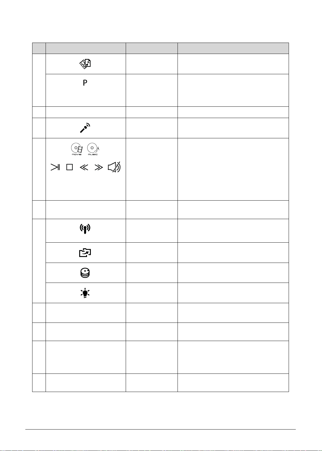
Table 1-1. Top View (Continued)
# Icon Item Description
3 Arcade key Launches InstantOn Arcade.
P key / Acer
PowerSmart key
Programmable key (configuration may
vary by model). / Puts your computer
into power-saving mode (configuration
may vary by model).
4 Keyboard For entering data into your computer
5 Microphone Internal microphone for recording
sound.
6
Touchpad /
Media Console
Touch-sensitive pointing device which
functions like a computer mouse*.
Touch sensitive controls for Acer
Arcade, volume (up/down) and media
(play/pause, stop, previous, next); with
mute.
* Touchpad becomes inactive when
Media Console is active.
7 Media Console
Turns Media Console on or off.
controller
8 Communication
key
Backup key
Enables/disables the computer’s
communication devices. (Communication
devices may vary by configuration.)
Launches Acer Backup Management for
three-step data backup.
HDD indicator
Power indicator
9 Click buttons
(left and right)
Indicates when the hard disk drive is active.
Indicates the computer’s power status.
The left and right buttons function like
the left and right mouse buttons.
10 Palm rest Comfortable support area for your hand
when using the computer.
11 Acer
Bio-Protection
Supports Acer FingerNav 4-way control
function (only for certain models).
fingerprint
reader
12 Speakers Left and right speakers deliver stereo
audio output.
1-14 Hardware Specifications and Configurations
Page 25

NOTE
Table 1-1. Top View (Continued)
# Icon Item Description
13 Power button /
Battery indicator
Turns the computer on and off.
Indicates the computer’s battery status.
Charging: The light shows amber
when the battery is charging.
Fully charged: The light shows blue
when in AC mode.
:
The front panel indicators are visible even when the computer cover is closed up.
Hardware Specifications and Configurations 1-15
Page 26
Media Console 0
Figure 1-2. Media Console
Media Console is a touch-sensitive entertainment interface including instant access to Acer
Arcade. Press the Media Console controller to activate Media Console. Press again to turn it
off and activate the touchpad.
Table 1-2. Media Console
Icon Item Description
Movie
Music
Play/pause
Stop
Previous
Next
Mute
Launch movie playback software.
Launch music playback software.
Play or pause a selected media file.
Stop playing the selected media file.
Return to the previous media file.
Jump to the next media file.
Turn the volume on or off.
1-16 Hardware Specifications and Configurations
Page 27
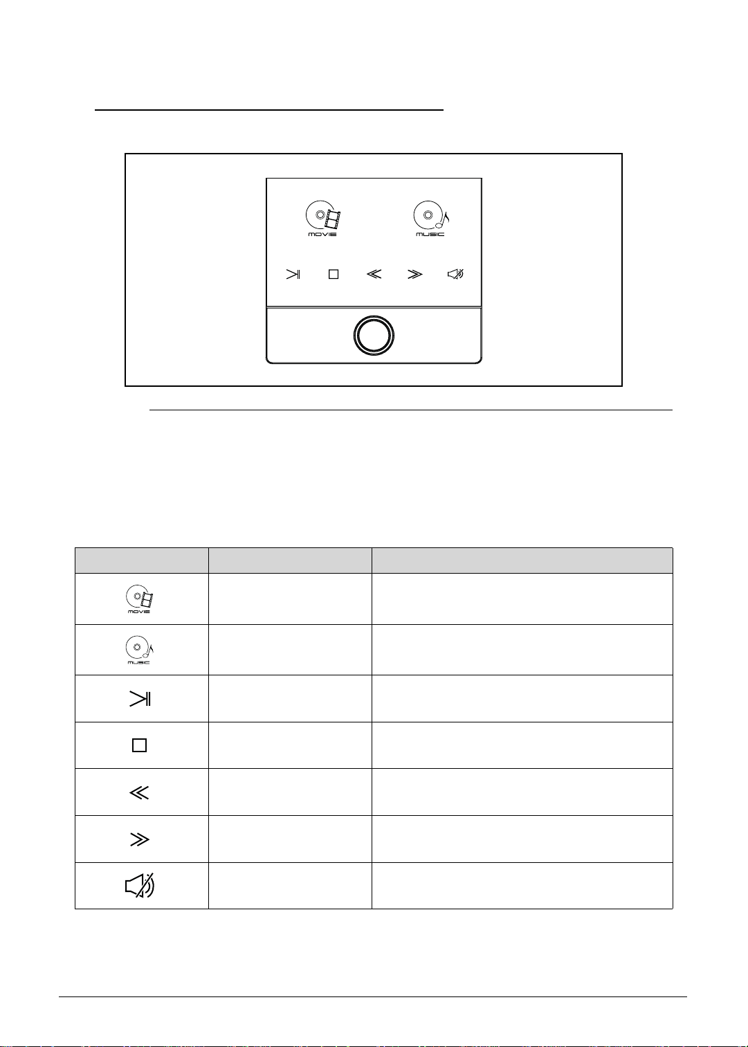
Closed Front View 0
NOTE
1
Figure 1-3. Closed Front View
Table 1-3. Closed Front View
# Icon Item Description
1 Thumbwheel Turn the volume up or down.
2 Multi-in-1 card reader Accepts Secure Digital (SD), MultiMediaCard
(MMC), Memory Stick (MS), Memory Stick
PRO (MS PRO), xD-Picture Card (xD).
3
2
:
Push to remove/install the card. Only one
card can operate at any given time.
3 CIR receiver Receives signals from a remote control.
Hardware Specifications and Configurations 1-17
Page 28
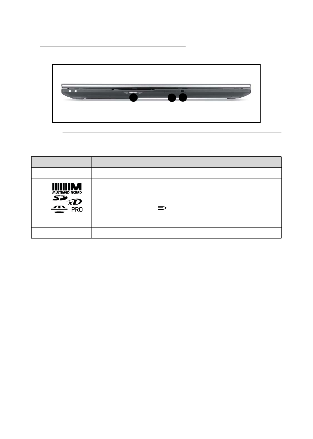
Rear View 0
A
Figure 1-4. Rear View
Table 1-4. Rear View
# Icon Item Description
1 Battery bay Houses the computer’s battery pack.
1-18 Hardware Specifications and Configurations
Page 29
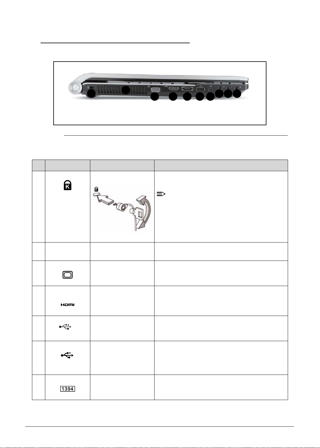
Left View 0
NOTE
1
Figure 1-5. Left View
Table 1-5. Left View
# Icon Item Description
1 Kensington lock slot Connects to a Kensington-compatible computer
2
3 4 5 6 7
security lock.
88 8
:
Wrap the computer security lock cable
around an immovable object such as a table
or handle of a locked drawer. Insert the lock
into the notch and turn the key to secure the
lock. Some keyless models are also
available.
2 Ventilation slots Enable the computer to stay cool, even after
prolonged use.
3 External display
(VGA) port
4 HDMI port Supports high definition digital video
5 USB 2.0 / eSATA port Connects to USB 2.0 or eSATA devices (only for
/e
SATA
6 USB 3.0 port Connects to USB devices. Supports the USB 3.0
7 4-pin IEEE 1394 port Connects to IEEE 1394 devices.
Hardware Specifications and Configurations 1-19
Connects to a display device (e.g. external
monitor, LCD projector).
connections.
certain models).
(SuperSpeed USB) specification.
* Devices without USB 3.0 certification may not
be compatible.
Page 30
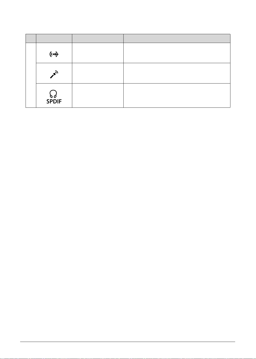
Table 1-5. Left View (Continued)
# Icon Item Description
8 Line-in jack Accepts audio line-in devices (e.g., audio CD
player, stereo walkman, mp3 player)
Microphone-in jack Accepts inputs from external microphones.
Headphones /
speaker / line-out jack
with S/PDIF support.
Connects to audio line-out devices (e.g.,
speakers, headphones).
1-20 Hardware Specifications and Configurations
Page 31

Right View 0
NOTE
4
1
1 1
Figure 1-6. Right View
Table 1-6. Right View
# Icon Item Description
1 USB 2.0 ports Connects to USB 2.0 devices (e.g., USB mouse,
2 Optical drive Internal optical drive; accepts CDs, DVDs, or
3 Optical disk access
indicator
4 Optical drive eject
button
5 Emergency eject hole Ejects the optical drive tray when the computer is
3
5
USB camera).
Blu-ray Discs (for certain models only).
Lights up when the optical drive is active.
Ejects the optical disk from the drive.
turned off.
6
7
:
Insert a paper clip to the emergency eject hole
to eject the optical drive tray when the
computer is off.
6 Ethernet (RJ-45) port Connects to an Ethernet 10/100/1000-based
network.
7 DC-in jack Connects to an AC adapter.
Hardware Specifications and Configurations 1-21
Page 32

Base View 0
1
3
2
4
5
6
Figure 1-7. Base View
Table 1-7. Base View
# Icon Item Description
1 Battery bay Houses the computer’s battery pack.
2 Subwoofer Emits low frequency sound output.
8
7
6
3 Battery release latch Releases the battery for removal.
4 Memory compartment Houses the computer’s main memory.
5 Hard disk bay- Main Houses the computer’s hard disk (secured with
screws)
6 Speakers Deliver stereo audio output.
7 Hard disk bay-
Secondary
8 Battery lock Locks the battery in position
1-22 Hardware Specifications and Configurations
Houses the computer’s hard disk (secured with
screws) (for certain models only)
Page 33

Touchpad Basics 0
1
2
3
Figure 1-8. Touchpad
Move your finger across the Touchpad (1) to move the cursor.
Press the left (2) and right (3) buttons located beneath the Touchpad to perform selection and
execution functions. These two buttons are the equivalent of the left and right buttons on a
mouse. Tapping on the Touchpad is the same as clicking the left button.
Table 1-8. Touchpad
Function Main TouchPad (1) Left Button (2) Right Button
Execute Tap twice (at the same speed as
Quickly click twice.
double-clicking a mouse button).
Select Tap once. Click once.
Drag Tap twice (at the same speed as
double-clicking a mouse button);
rest your finger on the TouchPad
Click and hold, then use
finger on the Touchpad
to drag the cursor.
on the second tap and drag the
cursor.
(3)
Access context
Click once.
menu
NOTE: When using the TouchPad, keep it - and fingers - dry and clean. The TouchPad is sensitive to
finger movement; hence, the lighter the touch, the better the response. Tapping too hard will not
increase the TouchPad’s responsiveness.
Hardware Specifications and Configurations 1-23
Page 34

Using the Keyboard 0
The computer has a close-to-full-sized keyboard and an embedded numeric keypad, separate
cursor, lock, function and special keys.
Figure 1-9. Keyboard Lock Keys
Lock Keys 0
The keyboard has three lock keys which can be toggled on and off.
Table 1-9. Keyboard Lock Keys
Lock key Description
Caps Lock When Caps Lock is on, all alphabetic characters typed are in uppercase.
Num Lock When Num Lock is on, the embedded keypad is in numeric mode. The keys
function as a calculator (complete with the arithmetic operators +, -, *, and /).
Use this mode when doing a lot of numeric data entry. A better solution would
be to connect an external keypad.
Scroll Lock
<Fn> + <F12>
When Scroll Lock is on, the screen moves one line up or down when the up or
down arrow keys are pressed respectively. Scroll Lock does not work with
some applications.
Embedded Numeric Keypad
The embedded numeric keypad functions like a desktop numeric keypad. It is indicated by
small characters located on the upper right corner of the key caps. To simplify the keyboard
legend, cursor-control key symbols are not printed on the keys.
Desired access Num Lock on Num Lock off
Number keys on embedded
keypad
Type numbers in a normal
manner.
Cursor-control keys on
embedded keypad
Main keyboard keys Hold <Fn> while typing letters
1-24 Hardware Specifications and Configurations
Hold <Shift> while using
cursor-control keys.
on embedded keypad.
Hold <Fn> while using
cursor-control keys.
Type the letters in a normal
manner.
Page 35

Windows Keys 0
The keyboard has two keys that perform Windows-specific functions.
Windows Logo key
Application key
Table 1-10. Windows Keys
Key Description
Windows Logo
key
Pressed alone, this key has the same effect as clicking on the Windows Start
button; it launches the Start menu. It can also be used with other keys to
provide a variety of functions.
Functions supported by Windows XP, Windows Vista, and Windows 7:
< >: Open or close the Start menu
< > + <R>: Open the Run dialog box
< > + <M>: Minimizes all windows
<SHIFT> + < > + M: Undo minimize all windows
< > + <F1>: Show the help window
< > + <E>: Open Windows Explorer
< > + <F>: Search for a file or folder
< > + <D>: Show the desktop
<CTRL> + < > + <F>: Search for computers (if you are on a network)
< > + <L>: Lock your computer (if you are connected to a network
domain), or switch users (if you're not connected to a network domain)
<CTRL> + < > + <TAB>: Moves focus from Start menu, to the Quick
Launch toolbar, to the system tray (use RIGHT ARROW or LEFT ARROW to
move focus to items on the Quick Launch toolbar and the system tray)
< > + <TAB>: Cycle through programs on the taskbar
< > + <BREAK>: Display the System Properties dialog box
Functions supported by Windows XP:
< > + <BREAK>: Show the System Properties dialog box
< > + <U>: Open Ease of Access Center
Application key This key has the same effect as clicking the right mouse button; it opens the
application's context menu.
Hardware Specifications and Configurations 1-25
Page 36

Hot Keys 0
The computer employs hot keys or key combinations to access most of the computer's
controls like screen brightness and volume output.
Figure 1-10. Keyboard Hot Keys
To activate hot keys, press and hold the <Fn> key before pressing the other key in the hockey
combination.
Table 1-11. Keyboard Hot Keys
Hot key Icon Function Description
<Fn> + <F3> Communication switch Enables/disables the computer’s
communication devices.
(Communication devices may
vary by configuration.)
<Fn> + <F4> Sleep Puts the computer in Sleep
mode.
<Fn> + <F5> Display toggle Switches display output between
the display screen, external
monitor (if connected) and both.
<Fn> + <F6> Screen blank Turns the display screen
backlight off to save power. Press
any key to return.
<Fn> + <F7> Touchpad toggle Turns the touchpad on and off.
<Fn> + <F8> Speaker toggle Turns the speakers on and off.
<Fn> + <
Z>
Brightness up Increases the screen brightness.
<Fn> + <
1-26 Hardware Specifications and Configurations
Y >
Brightness down Decreases the screen brightness.
Page 37

Table 1-11. Keyboard Hot Keys (Continued)
Hot key Icon Function Description
<Fn> + <Home> Play/Pause Plays or pauses media files
<Fn> + <Pg Up> Stop Stops media file
<Fn> + <Pg Dn> Previous Plays the previous media file in
the play sequence
<Fn> + <End> Next Plays the next media file in the
play sequence
Hardware Specifications and Configurations 1-27
Page 38

System Block Diagram
Front Speaker
Front Stereo Amp
(G1453L/ 2W+2W)
Center Mono Amp
(G1442/ 2W)
Center Speaker
USB 2
FingerPrint
USB 4
CCD
USB 8
USB 1, 3, 11, 12
Bluetooth
USB 9
USB 2.0 Port x 3
eSATA Conn.
(Debug)
eSATA Buffer
Speaker
Line in
MIC JackS/PDIF SUBWOOFER
Int. D-MIC
K/B COON.
CIR
& Head phone
TPA6047
(TPA311D1)
Touch Pad
Rear Audio Amp
Sub-Amplifier
DDR III
SATA1
SATA0
6.0 GT/s
SATA
<PCH>
Graphics Interfaces
INT_LVDS
INT_HDMI
HDMI
HDD (SATA) *2
intel
INT_CRT
SO-DIMM 0
SO-DIMM 1
SO-DIMM 2
SO-DIMM 3
DPLL_REF_SSCLK: 120MHz
BCLK: 133MHz
800 MT/s 1066 MT/s
1066/ 1333 MHz
Dual Channel
PEG_CLK: 100MHz
FDI interface
DDR SYSTEM MEMORY
FDI
rPGA 989
(37.5mm X 37.5mm)
X4 DMI interface
(128Mb/64Mb x 32 IO x 8 pcs)
2GB/1GB
DMI
PCI-E
X16
2.5GT/s
PCIE
AMD GPU
Granville-Pro / Whistle-Pro
DMIFDI
<MCH Processor>
Sandy Bridge
intel
Audio C ODEC
ALC669X
Azalia
USB 2.0
4MB x1 (Basic ME+Braidwood)
SPI ROM
HDA
USB
SPI
mBGA 989
(27mm X 25mm)
SPI ROM
IEEE1394a
connector
EC (WPC791)
LPC
IEEE1394 &
Media Cardreader
JM388A
RTC
P9
X'TAL
32.768KHz
PCI-E
2.5GT/s
SATA4
3.0 GT/s
PCI-Express
ODD (SATA)
SATA5
SATA
CougarPoint
PCIE-2
Card Reader
Connector
24.576MHz
RJ45 Connector
Transformer
25MHz
X'TAL
X'TAL
Giga-LAN
RTL8111E
Realtek
CLKOUT_PCIE2 CLKOUT_PEG_B
PCIE-5
PCIE-6
CLKOUT_PEG_1&2
USB 10
WLAN
PCIE-3 & 6
Mini Card
CLKOUT_PEG_3
USB3.0 Chip
UPD720200F1
USB 3.0 Conn .
HDMI
X'TAL
27.0MHz
CRT
LVDS
LVDS_CRT
Switch Graphics
LVDS
CRT
Figure 1-11. System Block Diagram
1-28 Hardware Specifications and Configurations
Page 39

Specification Tables 0
NOTE
Computer specifications
Item Metric Imperial
Dimensions
Length 295mm 11.6”
Width 440mm 17.3”
Height
(front to rear)
Weight (equipped with optical
drive, flash drive, and battery)
Input power
Operating voltage 19V 19V
Operating current 6.23A 6.23A
Temperature
Operating (not writing to
optical disc)
Operating (writing to optical
disc)
Nonoperating 20°C to 65°C -4°F to -149°F
Relative humidity
Operating 20% to 80%
Nonoperating 20% to 80%
Maximum altitude (unpressurized)
0°C~35°C 32°F to 95°F
5
°C to 35°C
39.4mm 1.6”
Glass SKU 3.9kg /
Non-glass SKU 3.6kg
41°F to 95°F
Glass SKU 8.6lbs /
Non-glass SKU 7.9lbs
Operating -15m to 3,048m -50 ft. to 10,000 ft.
Nonoperating -15m to 12, 192m -50 ft. to 40,000 ft.
Shock
Operating 30G/X,Y axis; 40G/Z axis;
3ms; half-sine
Nonoperating 30G/X,Y axis; 40G/Z axis;
3ms; half-sine
Random vibration
Operating 0.6G/5~500 HZ/30 min per axis
Nonoperating 1.5G/5~500HZ/30 min per axis
30G/X,Y axis; 40G/Z axis;
3ms; half-sine
30G/X,Y axis; 40G/Z axis;
3ms; half-sine
:
Applicable product safety standards specify thermal limits for plastic surfaces. The computer
operates well within this range of temperatures.
Hardware Specifications and Configurations 1-29
Page 40

System Board Major Chips
Item Specification
Core logic Intel Ibex-Peak HM65
VGA Internal: Integrated Graphics Controller
External: ATI Granville-pro/Wistler-pro
LAN Realtek RTL8111EA-VB-GR
USB 2.0 Integrated with PCH
USB 3.0 NEC UPD720200AF1-DAP-A
Super I/O controller Nuvoton NPCE791C
Bluetooth U SB
Wireless At heros HB97
PCMCIA N/ A
Audio codec Realtek ALC669X-GR
Card reader JMB388-QGAZ0A
eSata TIC SN75LVCP412A
Processor
Item Specification
CPU type Intel Sandy bridge QC (i7 -7/8/9) processors
MCP (Multi-Chip Package) CPU
CPU package 989 pins-rPGA socket
Core Logic Four-core processor
32-KB instruction and 32 -KB data first-level cache (L1) for each core
256-KB shared instruction/data second -level cache (L2) for each core
Up to 8-MB shared instruction/data last -level cache (L3), shared among all
cores
Chipset HM65
1-30 Hardware Specifications and Configurations
Page 41

Processor Specifications
Item CPU
Speed
(GHz)
Cores/
Threads
Bus
Speed
(FSB/
Mfg
Tech
(nm)
Cache
Size
Package Volta g e
DMI/QBI)
i7-2620M 2.7 4 DMI/QPI 32 nm 4 MB LGA-1155 35W
i7-2630QM 2.0 4 DMI/QPI 32 nm 6 MB LGA-1155 35W
i7-2720QM 2.2 4 DMI/QPI 32 nm 6 MB LGA-1155 35W
i7-2820QM 2.3 4 DMI/QPI 32 nm 8 MB LGA-1155 35W
CPU Fan True Value Table (TJ100-CPU)
CPU Temperature (°C) Fan Speed (RPM) SPL Spec (dBA)
45 2850 31
56 3150 34
70 3450 37
83 3800 40
96 5v 5v
Throttling 50%: On = 97°C; Off = 90°C
OS & HW Shutdown: 100°C
System Memory
Item Specification
Memory controller Built in CPU
Memory size 1GB, 2GB, & 4GB
DIMM socket number 4
Supports memory size per socket 4GB
Supports maximum memory size 16GB
Supports DIMM type DDR3
Supports DIMM Speed 800/1066/1333 MHz
Support DIMM voltage 1.5V ± 0.075V
Supports DIMM package 204-pin SODIMM
Hardware Specifications and Configurations 1-31
Page 42

Memory Combinations
Slot 1 (MB) Slot 2 (MB) Slot 3(MB) Slot 4(MB) Tota l M e m o r y
(MB)
0 0 0 1024 1024
0 0 1024 0 1024
0 1024 0 0 1024
1024 0 0 0 1024
0 0 1024 1024 2048
0 1024 1024 0 2048
1024 1024 0 0 2048
1024 0 0 1024 2048
0 1024 1024 1024 3072
1024 1024 1024 0 3072
1024 1024 0 1024 3072
1024 0 1024 1024 3072
1024 1024 1024 1024 4096
0 0 0 2048 2048
0 0 2048 0 2048
0 2048 0 0 2048
2048 0 0 0 2048
0 0 2048 2048 4096
0 2048 2048 0 4096
2048 2048 0 0 4096
2048 0 0 2048 4096
0 2048 2048 2048 6144
2048 2048 2048 0 6144
2048 2048 0 2048 6144
2048 0 2048 2048 6144
2048 2048 2048 2048 8192
0 0 0 4096 4096
0 0 4096 0 4096
0 4096 0 0 4096
4096 0 0 0 4096
0 0 4096 4096 8192
0 4096 4096 0 8192
1-32 Hardware Specifications and Configurations
Page 43

Slot 1 (MB) Slot 2 (MB) Slot 3(MB) Slot 4(MB) Tota l M e m o r y
(MB)
4096 4096 0 0 8192
4096 0 0 4096 8192
0 4096 4096 4096 12288
4096 4096 4096 0 12288
4096 4096 0 4096 12288
4096 0 4096 4096 12288
4096 4096 4096 4096 16384
Video Interface
Item Specification
Chipset ATI Granville-pro/Wistler-pro
Package 962-pins FCBGA 29mm x 29mm
Interface PCI-E x16
Compatibility Granville supports Microsoft® DirectX 11 with Shader Model
5.0, PCI Express® Revision 2.0, VESA DisplayPort™
technologies, and integrated HDMI™. The Unified Video
Decoder 2.0 (UVD 2) enables support for dual-stream decode
of High Definition (HD) and Standard Definition (SD) content
(H.264, VC-1, or MPEG-2 formats).
In addition, Granville supports 7.1 channels of compressed HD
Audio with Digital Rights Management (DRM).
Sampling rate Maximum pixel frequency of 400 MHz.
BIOS
Item Specification
BIOS vendor Insyde
BIOS Version V1.01
BIOS ROM type W25X16AVSSIG W25Q32BVSSIG
BIOS ROM size 512KB 4MB
Features SPI interface
Hardware Specifications and Configurations 1-33
Page 44

LAN Interface
Item Specification
LAN Chipset Realtek RTL8111EA-VB-GR
LAN connector type RJ45
LAN connector location Right side
Features
Keyboard
Integrated 10/100/1000base-T transceiver
Automatic MDI crossover function
PCIe v1.1 compliant
10/100/1000BASE-T full-duplex/half-duplex MAC
Receive side scaling (RSS) for multicore processors
Complies with IEEE802.3, 802.3u, 802.3ab and 802.1p
Supports iSCSI boot
IPv4 and IPv6 large send offload and checksum offload
(LSO/TCO)
Wake on LAN(WOL) support meeting the ACPI requirements
Statistics for SNMP MIB II, Ethernet-like MIB and Ethernet
MIB(IEEE 802.3z, Clause 30)
SMBus interface supporting Alert Standard Format (ASF)
v2.0
Self-boot feature, utilizing smaller EEPROM size with ability
to use on-chip memory
Serial Flash memory support with auto-sensing capability
PCI Express CLKREQ# support
Integrated switching regulator for improved power
consumption
Item Specification
Type
Acer AF7P_A10S AF7P
Total number of keypads US/UK 129 keys, JP 132 keys
Windows logo key Yes
Internal & external keyboard
Plug USB keyboard to the USB port directly: Yes
work simultaneously
Features
Support Application keys for Windows Vista / Windows 7
Multi-Langue support
1-34 Hardware Specifications and Configurations
Page 45

Hard Disk Drive (AVL components)
Item Specification
Vendor &
Model Name
Hitachi
HTS545012B9A300,
HTS545012B9SA00
Western Digital
WD1600BPVT,
WD1600BEVT,
Hitachi
HTS545016B9A300,
HTS545016B9SA00,
HTS543216A7A384,
Toshiba
MK1665GSX,
Seagate
ST9160316AS
Western Digital
WD2500BPVT-22A23
T0,
WD2500BEVT-22A23
T0,
Hitachi
HTS545025B9A300,
HTS545025B9SA00,
HTS543225A7A384
Toshiba
MK2565GSX,
Seagate
ST9250315AS,
HGST
AB545025015
Capacity (GB) 120 160 250
Bytes per sector 512 4096, 512, 512, 512,
512, 512, 512
4096, 512, 512, 512,
512, 512, 512, 512
Data heads 1 1, 1, 2, 2, 1/2, 1, 1 2, 2, 2, 2, 2, 2, 2, 2
Drive Format
Disks 1 1, 1, 1, 1, 1, 1, 1 1, 1, 1, 1, 1, 1, 1, 1
Spindle speed
5400
(RPM)
Performance Specifications
Buffer size 8MB
Interface SATA
Fast data transfer
3.0
rate
(Mbits / sec, max)
Media data transfer
rate
(Mbytes/sec max)
875 108, 106, 845, 845,
994.875, (464
-1148MBits/s), 1175
108, 106, 845, 875,
953, (464
-1148Mbits/s), 1175,
1031.7
DC Power Requirements
Voltage tolerance 5V ±5%
Hardware Specifications and Configurations 1-35
Page 46

Item Specification
Vendor &
Model Name
Capacity (GB) 320 500
Bytes per sector 4096, 512, 512, 4096,
Data heads 2, 1, 3, 4, 2, 1, 2, 2, 3 3, 4, 4, 4, 4, 4, 4
Western Digital
WD3200BPVT-22A23
T0,
WD3200BEVT-22A23
T0,
Hitachi
HTS545032B9A300,
HTS545032B9SA00,
HTS543232A7A384
Tos hi ba
MK3265GSX,
Seagate
ST9320315AS,
ST9320312AS,
ST9320310AS,
HGST
AB545032018
512, 512, 512, 512
Western Digital
WD5000BPVT,
WD5000BEVT-22A0RT,
Hitachi
HTS545050B9A300,
HTS545050B9SA00
Toshiba
MK5065GSX,
Seagate
ST9500325AS,
ST9400321AS
512, 512, 512, 512, 512, 512, 4096
Drive Format
Disks 1, 1, 2, 2, 1, 1, 1, 1, 2 2, 4, 2, 2, 2, 2, 2
Spindle speed
(RPM)
Performance Specifications
Buffer size 8MB
Interface SATA
Fast data transfer
rate
(Mbits / sec, max)
Media data transfer
rate
(Mbytes/sec max)
DC Power Requirements
Voltage tolerance 5V ±5%
108, 106, 875, 875,
(464 -1148Mbits/s),
1175, 1175, 1175,
1273.3
106, 845, 875, 875, 1031.7, 1175, 1175
5400
3.0
1-36 Hardware Specifications and Configurations
Page 47

Item Specification
Vendor &
Model Name
Western Digital
WD6400BPVT,
Tos hi ba
MK6465GSX,
Western Digital
WD7500BPVT,
Toshiba
MK7559GSXP
Seagate
ST9640322AS,
ST9640320AS
Capacity (GB) 640 750
Bytes per sector 512, 512, 4096, 512 512, 512
Data heads 4, 4, 4, 4 4, 4
Drive Format
Disks 2, 2, 2, 2 2, 2
Spindle speed
5400
(RPM)
Performance Specifications
Buffer size 8MB
Interface SATA
Fast data transfer
3.0
rate
(Mbits / sec, max)
Media data transfer
rate
97, (464 -1148
Mbits/s), 1175, 1175,
(Mbytes/sec max)
DC Power Requirements
Voltage tolerance 5V ±5%
97, (584.3-1195.5
Mbits/s)
Hardware Specifications and Configurations 1-37
Page 48

Super-Multi Drive
Item Specification
Vendor &
Model name
Performance
Specification
Transfer rate
(KB/sec)
Buffer Memory 1 MB
Interface SA TA
Applicable disc
format
With CD
Diskette
Sustained:
Max 3.6 (24x)
DVD:
DVD-ROM: 4.7GB (Single Layer) 8.5GB (Dual Layer)
DVD-R: 3.95GB (Ver. 1.0: read only) 4.7GB (Ver. 2.0 for Authoring: read
only)
4.7GB (Ver. 2.1 for General: read & write)
(DL) 8.5GB (Ver. 3.0)
DVD-RW: 4.7GB (Ver. 1.2/ Rev 1.0,
2.0, 3.0)
DVD-RAM: 4.7GB/side (Ver. 2.2)
DVD+R: 4.7GB (Ver. 1.3)
(DL) 8.5GB (Ver. 1.1)
DVD+RW: 4.7GB (Vol.1 Ver.1.3)
CD:
CD-ROM Mode-1 data disc
CD-ROM Mode-2 data disc
CD-ROM XA, CD-I, Photo-CD MultiSession, Video CD
CD-Audio Disc
Mixed mode CD-ROM disc (data and audio)
CD-Extra
CD-Text
CD-R (Conforming to “Orange Book Part 2”: read & write)
CD-RW (Conforming to “Orange Book Part 3”: read & write)
HLDS
GT32N
With DVD
Diskette
Sustained:
Max 11.08 (8x)
With CD
Diskette
Sustained:
Max 3.6 (24x)
HLDS
GT34N
With DVD
Diskette
Sustained:
Max 11.08 (8x)
Loading
mechanism
Power Requirements
Input Voltage 5 V +/- 5% (Operating)
1-38 Hardware Specifications and Configurations
Electrical Release (Release Button)
Release by ATAPI command
Emergency Release
Page 49

Item Specification
Vendor &
Model name
Performance
Specification
Transfer rate
(KB/sec)
With CD
Diskette
Sustained:
Max 3.6 (24x)
Panasonic
UJ8A0
With DVD
Diskette
Sustained:
Max 10.8 (8x)
With CD
Diskette
Sustained:
Max 3.6 (24x)
Buffer Memory 1 MB
Interface SA TA
Applicable disc
format
DVD:
DVD-VIDEO, DVD-ROM,
DVD-R(4.7GB), DVD-R DL
DVD-RW(Ver.1.1/1.2)
DVD+R, DVD+R DL, DVD+RW
DVD-RAM(4.7GB)
CD:
CD-DA, CD-ROM, CD-ROM XA, PhotoCD (multisession), Video CD,
Cd-Extract (CD+), CD-text
Loading
mechanism
Electrical Release (Release Button)
Release by ATAPI command
Emergency Release
Panasonic
UJ890
With DVD
Diskette
Sustained:
Max 10.8 (8x)
Power Requirements
Input Voltage DC 5V +/- 0.25V
Hardware Specifications and Configurations 1-39
Page 50

Item Specification
Vendor &
Model name
Performance
Specification
Transfer rate
(KB/sec)
Buffer Memory 4 MB 1.5 MB
Interface SA TA
Applicable disc
format
With CD
Diskette
Sustained:
- CD-ROM inside
1.545
- CD-ROM
outside 3.6
BD-RE Ver2.1 (Read only)
BD-R Ver1.1 & 1.2 & 1.3 (Read only)
BD-ROM (with copy protection) and
BD9
KODAK Photo CD Single and
Multi-session
CD Extra (CD PLUS)
Video CD
CD text data (Read/Write)
CD-R discs (Read/Write)
CD-RW discs (Read/Write)
DVD-R Ver.2.0 & 2.1 for General
(Read/Write)
DVD-R DL Ver.3.0 (Read/Write)
DVD-RW Ver.1.0 & 1.1 & 1.2
(Read/Write)
DVD+R Ver.1.3 (Read/Write)
DVD+R DL Ver1.0 & 1.1
(Read/Write)
DVD+RW Ver.1.3 & high speed
Ver.1.0 (Read/Write)
DVD-RAM Ver.2.0 & 2.1 & 2.2
(Read/Write: RAM2 Read only)
Pioneer
BDC-TD03RS
With DVD
Diskette
Sustained:
- DVD inside
4.455
- DVD outside
10.8
- DVD-RAM
inside 4.155
- DVD-RAM
outside 6.925
Pioneer
DVR-TD10RS
With CD
Diskette
Sustained:
- CD-ROM inside
1.5
- CD-ROM
outside 3.6
KODAK PhotoCD Single and
Multi-session
CD Extra (CDPLUS)
Video CD
CD text data (Read/Write)
CD-R discs (Read/Write)
CD-RW discs (Read/Write)
DVD-ROM
DVD-R Ver.2.0 &2.1 for General
(Read/Write)
DVD-R DL Ver.3.0 (Read/Write)
DVD-RW Ver.1.0&1.1&1.2
(Read/Write) DVD+R
Ver.1.3 (Read/Write)
DVD+R DL Ver1.0&1.1 (Read/Write)
DVD+RW
Ver.1.3 (Read/Write)
DVD+RW high speed Ver.1.0
(Read/Write)
DVD-RAM Ver.2.0&2.1&2.2 (*1)
With DVD
Diskette
Sustained:
- DVD-R inside
2.7
- DVD-R outside
10.8
- DVD+R inside
3.24
- DVD+R outside
10.8
Loading
mechanism
Power Requirements
Input Voltage 5V +/- 5% (Operating)
1-40 Hardware Specifications and Configurations
Electrical Release (Release Button)
Release by ATAPI command
Emergency Release
Page 51

Item Specification
Vendor &
Model name
Performance
Specification
Transfer rate
(KB/sec)
With CD
Diskette
Sustained:
Max 3.6 (24x)
Panasonic
UJ8A0
With DVD
Diskette
Sustained:
Max 10.8 (8x)
With CD
Diskette
Sustained:
Max 3.6 (24x)
Buffer Memory 1 MB
Interface SA TA
Applicable disc
format
DVD:
DVD-VIDEO, DVD-ROM,
DVD-R(4.7GB), DVD-R DL
DVD-RW(Ver.1.1/1.2)
DVD+R, DVD+R DL, DVD+RW
DVD-RAM(4.7GB)
CD:
CD-DA, CD-ROM, CD-ROM XA, PhotoCD (multisession), Video CD,
Cd-Extra (CD+), CD-text
Loading
mechanism
Electrical Release (Release Button)
Release by ATAPI command
Emergency Release
Panasonic
UJ890
With DVD
Diskette
Sustained:
Max 10.8 (8x)
Power Requirements
Input Voltage DC 5V +/- 0.25V
Hardware Specifications and Configurations 1-41
Page 52

Item Specification
Vendor &
Model name
Performance
Specification
Transfer rate
(KB/sec)
Buffer Memory 1.5 MB
Interface SA TA
Applicable disc
format
PLDS
DS-8A5SH
With CD
Diskette
Sustained:
- CD-ROM inside
1.45
- CD-ROM
outside 3.5
DVD:
DVD-ROM (4.7G/8.54G) single layer
on single/double side (Read Only),
DVD-ROM dual layer (PTP/OTP) on
single/double side (Read Only),
DVD-RW, DVD+RW, DVD-R (4.7G
for General), DVD+R, DVD+R9,
DVD-R9, DVD-RAM(4.7G)
CD:
CD-ROM, CD-R and CD-RW
With DVD
Diskette
Sustained:
- DVD-ROM
inside 3.7
- DVD-ROM
outside 10
Loading
mechanism
Power Requirements
Input Voltage
Manual load
Plunger system
1-42 Hardware Specifications and Configurations
Page 53

BD Drive
Items Specifications
Vendor &
Model name
Performance
With CD Diskette With DVD Diskette With BD Diskette
Panasonic
UJ141AL
Specification
Transfer rate
(KB/sec)
Sustained:
Max 36 (24x)
Sustained:
Max 10800 (8x)
Buffer Memory 2 MB
Interface SA TA
Applicable disc
format
DVD:
DVD-VIDEO, DVD-ROM, DVD-R(4.7GB), DVD-RW(Ver.1.1/1.2),
DVD-RAM, DVD+R, DVD+R DL, DVD+RW, DVD-R DL(Format1/4)
CD:
CD-DA, CD-ROM, CD-ROM XA, PhotoCD (multisession), VideoCD,
CD-Extra (CD+), CD-text, Hybrid SACD
BD:
BD-ROM (1.0), BD-R (1.0), BD-RE (2.0)
Loading mechanism Electrical Release (Release Button)
Release by ATAPI command
Emergency Release
Sustained:
Max 27000 (1.6x CLV,
2x CLV, 4x, 6x CAV)
Power Requirement
Input Voltage DC 5V +/- 0.25V
Hardware Specifications and Configurations 1-43
Page 54

Items Specifications
Vendor &
Model name
Performance
Specification
Transfer rate
(KB/sec)
Buffer Memory 2 MB
Interface SA TA
Applicable disc
format
Loading mechanism Electrical Release (Release Button)
With CD Diskette With DVD Diskette With BD Diskette
Sustained:
Max 3600 (24x)
DVD:
DVD-VIDEO, DVD-ROM, DVD-R(4.7GB), DVD-RW(Ver.1.1/1.2),
DVD-RAM, DVD+R, DVD+R DL, DVD+RW, DVD-R DL(Format1/4)
CD:
CD-DA, CD-ROM, CD-ROM XA, PhotoCD (multisession), VideoCD,
CD-Extra (CD+), CD-text, Hybrid SACD
BD:
BD-ROM(1.0), BD-R(1.0), BD-RE(2.0)
Release by ATAPI command
Emergency Release
Panasonic
UJ240
Sustained:
Max 10800 (8x)
Sustained:
Max 27000 (1.6x CLV,
2x CLV, 4x, 6x CAV)
Power Requirement
Input Voltage DC 5V +/- 0.25V
1-44 Hardware Specifications and Configurations
Page 55

Items Specifications
Vendor &
Model name
Performance
With CD Diskette With DVD Diskette With BD Diskette
PLDS
DS-4E1S
Specification
Transfer rate
(KB/sec)
Sustained:
- CD-ROM inside
1450
- CD-ROM outside
3500
Sustained:
- DVD-ROM inside
4300
- DVD-ROM outside
10000
Buffer Memory 2 MB
Interface SATA
Applicable disc
format
DVD:
DVD-ROM (4.7G/8.54G) single layer on single/double side (Read
Only), DVD-ROM dual layer (PTP/OTP) on single/double side (Read
Only), DVD-R (3.9G, 4.7G for General and Authoring), DVD-RW,
DVD+RW (4.7G), DVD+R, DVD+R DL, DVD-R DL, DVD-RAM
CD:
CD-ROM, CD-R and CD-RW
BD:
BD-ROM, BD-ROM DL, BD-R, BD-R DL, BD-RE, BD-RE DL,
BD-hybrid (only BD part)
Sustained:
- BD-ROM SL inside
7500
- BD-ROM SL outside
18000
Loading mechanism Manual load/ Plunger system
Power Requirement
Input Voltage 5V +/- 5%
Hardware Specifications and Configurations 1-45
Page 56

LED 18.4”
Item Specification
Vendor &
Model name
CHI MEI
N184H6-L02
Screen Diagonal (mm) 469.13 (18.47”)
Active Area (mm) 408.6 (H) x 234.24 (V)
16.09” (H) x 9.22“(V)
Display resolution (pixels) 1920 x R.G.B x 1080
Pixel Pitch (mm) 0.213 (H) x 0.213 (V)
Typical White Luminance (cd/m
2
)
220
also called Brightness
Contrast Ratio 650:1 (typical)
500:1 (min)
Response Time (Optical Rise
Time/Fall Time) msec
2 (typical), 8 (max) /
6 (typical), 12 (max)
Typical Power Consumption (watt) 4.6
Weight (without inverter) 620 (typical)
635 (max)
Physical Size (mm) 422 x 247.5 x (min)
422.5 x 248 x 6 (typical)
423 x 248.5 x 6.3 (max)
Electrical Interface 40 pins LVDS
Viewing Angle (degree)
Horizontal (Right) CR = 10 (Left)
Vertical (Upper) CR = 10 (Lower)
45 / 45 / 20 / 45 (typical)
40 / 40 / 15 / 40 (min)
LCD Inverter (not available with this model)
Item Specification
Vendor & Model name
Brightness conditions
Input voltage (v)
Input current (mA)
Output voltage (V, RMS)
Output current (mA, RMS)
Output voltage frequency
(KHz)
1-46 Hardware Specifications and Configurations
Page 57

Display Supported Resolution (LCD Supported Resolution)
Resolution 16 bits 30 bits 36 bit 48 bit
640x480p/60Hz 4:3 Yes Yes Yes Yes
720x480p/60Hz 4:3 Yes Yes Yes Yes
720x480p/60Hz 16:9 Yes Yes Yes Yes
1280x720p/60Hz 16:9 Yes Yes Yes Yes
1920x1080i/60Hz 16:9 Yes Yes Yes Yes
1440x480i/60Hz 4:3 Yes Yes Yes Yes
1440x480i/60Hz 16:9 Yes Yes Yes Yes
1920x1080p/60Hz 16:9 Yes Yes Yes Yes
720x576p/50Hz 4:3 Yes Yes Yes Yes
720x576p/50Hz 16:9 Yes Yes Yes Yes
1280x720p/50Hz 16:9 Yes Yes Yes Yes
1920x1080i/50Hz 16:9 Yes Yes Yes Yes
1440x576i/50Hz 4:3 Yes Yes Yes Yes
1440x576i/50Hz 16:9 Yes Yes Yes Yes
1920x1080p/50Hz 16:9 Yes Yes Yes Yes
Graphics Controller
Item Specification
VGA Chip AMD Radeon™ HD 6850M AMD Radeon™ HD 6650M
Supports
Unified Video Decoder 2 (UVD 2)
OpenEXR High Dynamic-Range
(HDR) technology
Shader Model 5.0
Microsoft® DirectX® 11
OpenGL® 3.1
OpenCL™ 1.1
Unified Video Decoder 3 (UVD 3)
OpenEXR High Dynamic-Range
(HDR) technology
Shader Model 5.0
Microsoft® DirectX® 11
OpenGL® 3.1
OpenCL™ 1.1
Display Supported Resolution (GPU Supported Resolution)
Resolution 16 bits 32 bits Intel AT I
800x600p/60Hz 16:9 Yes Yes Yes Yes
1024x768p/60Hz 16:9 Yes Yes Yes Yes
1280x600/60Hz 16:9 Yes Yes Yes
1280x720/60Hz 16:9 Yes Yes Yes Yes
1280x768/60Hz 16:9 Yes Yes Yes Yes
1360x768/60Hz 16:9 Yes Yes Yes Yes
1366x768/60Hz 16:9 Yes Yes Yes Yes
Hardware Specifications and Configurations 1-47
Page 58

Bluetooth Interface
Item Specifications
Chipset Atheros AR3011 Broadcom BCM2070
Data throughput TX 1.2Mbits/sec
RX 1.2Mbits/sec
TX 1.2Mbits/sec
RX 1.2Mbits/sec
Protocol 3.0+HS 3.0+HS
Interface USB 2.0 USB 2.0
Connector type JST SM08B SURS - TF JST SM06B-XSRK-ETB
Supported protocol 2.1, 3.0 2.1, 3.0
Bluetooth Module
Item Specifications
Controller AR3011
Feature
Single-chip Bluetooth v2.1/3.0 + EDR integrated solution
USB 2.0 full-speed device interface with support for Device
Firmware Upgrade (DFU)
SPI interface supports external serial flash devices
Two on-chip 1.2V linear voltage regulators
Integrated 32-bit CPU with 32KB data RAM and 256KB
program RAM
On-board PLL
On-chip low power oscillator (LPO)
WLAN coexistence interface
Standard USB HCI interface
Controller BCM2070
Features
Bluetooth 2.1 compliant
Point-to-multipoint operation
External USB interface for data
Onboard antenna and SMA RF connector
Coexistence support
Camera
Item Specification
Vendor &
Model
Type CMOS image sensor
Chicony 1.3 MB
CH9665SN (CNF9155)
with SXGA
Suyin 1.3MB
SY9665SN
CMOS image sensor
with SXGA
Liteon 1.3MB
LT9665AL (09P2SF119)
CMOS image sensor
with SXGA
1-48 Hardware Specifications and Configurations
Page 59

Mini Card
Item Specification
Number supported 2
TV tuner DVB-T/ATSC: Not supported
DVB-T Half Minicard: Not supported
Features Not available
3G Card (not available in this model)
Item Specification
Features
Hardware Specifications and Configurations 1-49
Page 60

Audio Codec and Amplifier
Item Specification
Audio Controller Realtek ALC669X-GR
Features
High performance DACs with digital >110dB and analog
98dB (A-weighting) signal-to noise]
High performance ADCs with digital > 100dB and analog
90dB (A-Weighting) signal-to noise ratio
Six DAC channels support 16/20/24-bit PCM format for 5.1
sound playback
Two stereo ADCs support 16/20/24-bit PCM format, multiple
stereo recording
All DACs supports 44.1k/48k/96k/192kHz sample rate
All ADCs supports 44.1k/48k/96k/192kHz sample rate
Primary 16/20/24-bit SPDIF-OUT supports
32k/44.1k/48k/88.2k/96k/192kHz sample rate
Secondary 16/20/24-bit SPDIF-OUT supports
32k/44.1k/48k/88.2k/96k/192kHz sample rate
Analog jacks (port-A, B, C, E and G) support stereo input and
output re-tasking
Port-B/C/E/F with software selectable boost gain
(+10/+20/+30dB) for analog microphone input
Supports external PCBEEP input and built-in digital BEEP
generator
Software selectable 2.5V/3.2V VREFOUT
Supports legacy analog mixer architecture
Four channels of digital microphone array input for voice
applications
Two jack detection pins each designed to detect up to 4 jacks
plugging
1.0dB/step playback volume control
1.5dB/step recording volume control
High pass filter to cancel DC offset from AD converter
Jack detection function is supported when device is in power
down mode (D3)
2 GPIOs (General Purpose Input and Output) for customized
applications. GPIO0 and
GPIO1 share
pin with digital microphone
Supports anti-pop mode when analog power AVDD is on and
digital power is off.
1-50 Hardware Specifications and Configurations
Page 61

Item Specification
Support MONO output at port-H
Port-A/D/E/F built in headphone amplifiers
Port-E and Port-F headphone amplifiers can drive earphone
directly without DC blocking capacitor
Audio Content Protection for Blu-Ray DVD playback (with
selected player provided by InterVideo, CyberLink and
ArcSoft)
Intel low power ECR compliant and power status control for
every analog converter and pin widgets
Supports 3.3V digital core power, 1.5V-3.3V scalable digital
I/O power for HD Audio link, and 3.0-5.0V analog power
Amplifier TPA311D1
Features Mono x1, front x1, surround x1, subwoofer x1
Audio Interface
Item Specification
Audio Controller Realtek ALC669X-GR
Audio onboard or optional Onboard
Mono or Stereo Stereo
Compatibility Microsoft WLP (Windows Logo Program)
Sampling rate 44.1k/48k/96k/192kHz
Internal microphone Yes
Internal speaker/quantity Yes / 6
1. Left Back (2W)
2. Right Back (2W)
3. Center Back (2W)
4. Subwoofer Back Bottom Panel (3W)
5. Surround L
6.
Surround R
eft Front (2W)
ight Front (2W)
Wireless Module 802.11b/g/n
Item Specification
Chipset Atheros HB97 BCM943225HM
Data throughput
11-54 Mbps, up to 300 Mbps for Draft-N 11-54 Mbps, up to 300 Mbps for Draft-N
Protocol b, g, n b, g, n
Interface PCI-E PCI-E
Hardware Specifications and Configurations 1-51
Page 62

Battery
Item Specification
Vendor & Model name SIMPLO AS10C
Battery Type Li-Ion
Pack capacity 6000mAh
Number of battery cell 8
Package configuration 4S2P
VRAM
Item Specification
Chipset AMD GPU
Whistle-Pro / Granville-Pro
Memory size 1GB / 2GB
Interface PCI-E
USB Port
Item Specification
USB compliance level Universal Serial Bus 2.0 Universal Serial Bus 3.0
specification Revision 1.0
Protocol EHCI, UHCI xHCI
Number of USB port(s) 3 1
Location Right side Left side
Output Current 1.05V 3.3V and 1.05V
HDMI Port
Item Specification
Compliance level HDMI 1.4a
Data throughput 5.4 Gbps
Number of HDMI port(s) 1
Location Right side
1-52 Hardware Specifications and Configurations
Page 63

AC Adapter
Item Specification
Input rating 120W
Maximum input AC current 1.8A Max at 120W
Inrush current I^2t at 264V
Efficiency More than 87% of average efficiency of 25%, 50%, 75% and
100% load tested at 115Vac and 230Vac.
System Power Management
Item Specification
Mech. Off (G3) Al devices in the system are turned off completely.
Soft Off (G2/S5) OS initiated shutdown. All devices in the system are turned off
completely.
Working (G0/S0) Individual devices such as the CPU and hard disc may be
power managed in this state.
Suspend to RAM (S3) CPU set power down
VGA Suspend
PCMCIA Suspend
Audio Power Down
Hard Disk Power Down
CD-ROM Power Down
Super I/O Low Power mode
Save to Disk (S4) Also called Hibernation Mode. System saves all system states
and data onto the disc prior to power off the whole system.
Card Reader
Item Specification
Chipset JMicron JMB388-QGAZ0A
Package QFN
Maximum supported size SD: up to 2 GB
SDHC: up to 32 GB
SDXC: up to 2TB
mini SD: as SD/SDHC
micro SD: as SD/SDHC
XD: up to 2GB
Memory Stick: up to 128MB
Memory Stick Duo: up to 128MB
Memory Stick Pro/Duo/HG: up to 32GB
Memory Stick XC (MSXC): up to 2TB
MMC: up to 2TB
Hardware Specifications and Configurations 1-53
Page 64

Item Specification
Features Compliant with PCI Express Base Spec. Revision 1.1
Compliant with 1394 Open Host Controller Interface (OHCI)
Release 1.1
Compliant with SD Spec. Part 1 Physical Layer Spec. Version
3.00
Compliant with SD Spec. Part A2 SD Host Controller
Standard Spec. Version 2.00
Compliant with SD Spec. Part E1 SDIO Spec. Version 2.00
Compliant with SD Spec. Part 2 File System Spec. Version
3.00
Compliant with MultiMediaCard System Spec. Version 4.2
Compliant with Memory Stick Standard Format Spec. Version
1.43-00
Compliant with Memory Stick Standard Memory Stick PRO
Format Spec. - without security spec. - Version 1.02-00
Compliant with Memory Stick Pro-HG Duo Spec. Version
1.00
Compliant with Memory Stick XC Duo Format Specification
ver.1.00-00
Compliant with Memory Stick XC-HG Duo Format
Specification ver.1.00-00
Compliant with Memory Stick XC Micro Format Specification
ver.1.00-00
Compliant with Memory Stick XC-HG Micro Format
Specification ver.1.00-00
Compliant with xD-Picture CardTM Card Spec. Version 1.20
Compliant with xD-Picture CardTM Host Guideline Version
1.20
Compliant with xD-Picture CardTM Host Compliance Design
Check Spec. Version 1.20D
Compliant with xD-Picture CardTM Format Spec. Version
1.11
Compliant with System Management Bus Specification
Revision 1.1
1-54 Hardware Specifications and Configurations
Page 65

System LED Indicator
Item Specification
Lock
System state
Caps Lock on = Blue
Caps Lock on = Blue
Blue color on: System on
Blue color and amber color off: System off
Amber color on: S3
HDD access state HDD access active = Blue
Wireless state Wifi on = Amber
Power button backlight
Battery state
Blue color solid on: System on
Blue color off: System off
Full charging = Blue
Battery charging = Amber
Back up state Back up active = Blue
Arcade module state Arcade module active = Blue
Finger print module state Finger print module active = Blue
System DMA Specification
Legacy Mode Power Management
DMA0 Not applicable
DMA1* Not applicable
DMA2* Not applicable
DMA3 Not applicable
DMA4 Direct memory access controller
DMA5* Not applicable
DMA6 Not assigned
DMA7 Not assigned
*ExpressCard controller can use DMA 1, 2, or 5.
Hardware Specifications and Configurations 1-55
Page 66

System Interrupt Specification
Hardware IRQ System Function
IRQ0 Sy stem timer
IRQ1 S tandard PS/2 Keyboard
IRQ2* Not in use
IRQ3* Not in use
IRQ4 Nuvoton CIR Transceiver
IRQ5* Not in use
IRQ6* Not in use
IRQ7* Not in use
IRQ8 System CMOS/real-time clock
IRQ9* Not in use
IRQ10* Not in use
IRQ11* Not in use
IRQ12 Synaptics PS/2 Port Touchpad
IRQ13 Numeric data processor
IRQ14* Not in use
IRQ15* Not in use
* Reserved for PCI device used
1-56 Hardware Specifications and Configurations
Page 67

System IO Address Map
I/O address (hex) System Function (shipping configuration)
000 - 01F Direct memory access controller
020 - 021 Programmable interrupt controller
024 - 025 Programmable interrupt controller
028 - 029 Programmable interrupt controller
02C - 02D Programmable interrupt controller
02E - 02F Motherboard resources
030 - 031 Programmable interrupt controller
034 - 035 Programmable interrupt controller
038 - 039 Programmable interrupt controller
03C - 03D Programmable interrupt controller
040 - 043 System timer
04E - 04F Motherboard resources
050 - 053 System timer
060 Standard PS/2 Keyboard
061 Motherboard resources
062 Microsoft ACPI-Compliant Embedded Controller
063 Mo therboard resources
064 Standard PS/2 Keyboard
065 Motherboard resources
066 Microsoft ACPI-Compliant Embedded Controller
067 Motherboard resources
068 Motherboard resources
06C Motherboard resources
070 Motherboard resources
070 - 077 System CMOS/real time clock
080 Motherboard resources
081 - 091 Direct memory access controller
092 Motherboard resources
093 - 09F Direct memory access controller
0A0 - 0A1 Programmable interrupt controller
0A4 - 0A5 Programmable interrupt controller
0A8 - 0A9 Programmable interrupt controller
Hardware Specifications and Configurations 1-57
Page 68

I/O address (hex) System Function (shipping configuration)
System IO Address Map (Continued)
0AC - 0AD Programmable interrupt controller
0B0 - 0B1 Programmable interrupt controller
0B2 - 0B3 Motherboard resources
0B4 - 0B5 Programmable interrupt controller
0B8 - 0B9 Programmable interrupt controller
0BC - 0BD Programmable interrupt controller
0C0 - 0DF Direct memory access controller
0F0 Numeric data processor
3B0 - 3BB AMD Radeon HD 68X0M
3C0 - 3DF AMD Radeon HD 68X0M
3C0 - 3DF PCI standard PCI-to-PCI bridge
400 -47F Motherboard resources
454 - 457 Motherboard resources
4D0 - 4D1 Programmable interrupt controller
500 - 57F Motherboard resources
680 - 69F Motherboard resources
610-617 Nuvoton CIR Transceiver
620-63F Nuvoton CIR Transceiver
800-80F Motherboard resources
CF8-CFF Motherboard resources
164E-164F Motherboard resources
2000-2FFF Car reader controller
3000-3FFF USB 3.0 controller
4000-4FFF Realtek PCIe GBE Family Controller
5000-5FFF AMD Radeon HD 68X0M
6000-601F SMbus Controller
6020-603F SATA AHCI controller
6040-6047 SATA AHCI controller
6048-604F SATA AHCI controller
6058-605B SATA AHCI controller
605C-605F SATA AHCI controller
E000-EFFF WLAN controller
1-58 Hardware Specifications and Configurations
Page 69

CHAPTER 2
System Utilities
Page 70

BIOS Setup Utility . . . . . . . . . . . . . . . . . . . . . . . . . . . . . . . . . . . . .2-3
Navigating the BIOS Utility . . . . . . . . . . . . . . . . . . . . . . . . . . . .2-3
BIOS . . . . . . . . . . . . . . . . . . . . . . . . . . . . . . . . . . . . . . . . . . . . . . . .2-4
Information. . . . . . . . . . . . . . . . . . . . . . . . . . . . . . . . . . . . . . . . .2-4
Main . . . . . . . . . . . . . . . . . . . . . . . . . . . . . . . . . . . . . . . . . . . . . .2-6
Security . . . . . . . . . . . . . . . . . . . . . . . . . . . . . . . . . . . . . . . . . . . . 2-8
Boot. . . . . . . . . . . . . . . . . . . . . . . . . . . . . . . . . . . . . . . . . . . . . . . 2-12
Exit . . . . . . . . . . . . . . . . . . . . . . . . . . . . . . . . . . . . . . . . . . . . . . .2-13
BIOS Flash Utilities. . . . . . . . . . . . . . . . . . . . . . . . . . . . . . . . . . . .2-14
DOS Flash Utility. . . . . . . . . . . . . . . . . . . . . . . . . . . . . . . . . . . . .2-15
WinFlash Utility . . . . . . . . . . . . . . . . . . . . . . . . . . . . . . . . . . . . . .2-17
Remove HDD/BIOS Password Utilities . . . . . . . . . . . . . . . . . . . .2-18
Removing BIOS Passwords . . . . . . . . . . . . . . . . . . . . . . . . . . . . 2-20
Miscellaneous Tools . . . . . . . . . . . . . . . . . . . . . . . . . . . . . . . . . .2-21
2-2
Page 71

System Utilities
NOTE
NOTE
BIOS Setup Utility 0
This utility is a hardware configuration program built into a computer’s BIOS (Basic
Input/Output System).
The utility is pre-configured and optimized so most users do not need to run it. If configuration
problems occur, the setup utility may need to be run. Refer to Chapter 4, Troubleshooting
when a problem arises.
To activate the utility, press
of screen.
The default parameter of F12 Boot Menu is set to Disabled. To change the boot device
without entering BIOS Setup Utility, set the parameter to Enabled.
To change the boot device without entering the BIOS SETUP, press F12 during POST to
enter the multi-boot menu.
Navigating the BIOS Utility 0
Six menu options are:
Information
Main
Security
Boot
Exit
To navigate through the following:
Menu - use the left and right arrow keys
Item - use the up and down arrow keys
Change parameter value - press F5 or F6.
Exit - Press Esc
Load default settings - press F9. Press F10 to save changes and exit BIOS Setup Utility
F2 during POST (power-on self-test) when prompted at the bottom
NOTE:
:
Parameter values can be changed if enclosed in square brackets [ ]. Navigation
keys appear at the bottom of the screen. Read parameter help carefully when
making changes to parameter values. Parameter help is found in the Item
Specific Help area of the screen.
NOTE:
:
System information is subject to specific models.
System Utilities 2-3
Page 72

BIOS 0
NOTE
The following is a description of the tabs found on the InsydeH20 BIOS Setup Utility screen:
NOTE:
:
The screens provided are for reference only. Actual values may differ by model.
Information 0
This tab shows a summary of computer hardware information.
Figure 2-1. BIOS Information
Table 2-1 describes the parameters shown in Figure 2-1
Table 2-1. BIOS Information
Parameter Description
CPU Type CPU (central processing unit) type and speed of system
CPU Speed Speed of the CPU
HDD0 Model Name Model name of HDD0 (hard disk drive) installed on primary IDE
master
HDD0 Serial Number Serial number of HDD0 installed on primary IDE master
HDD1 Model Name Model name of HDD1 installed on primary IDE master
HDD1 Serial Number Serial number of HDD1 installed on primary IDE master
2-4 System Utilities
Page 73

Table 2-1. BIOS Information (Continued)
Parameter Description
ATAPI Model Name Model name of Optical device installed in system
System BIOS Version System BIOS version
VGA BIOS Version VGA (video graphics array) firmware version of system
Serial Number Serial number of unit
Asset Tag Number Asset tag number of system
Product Name Product name of the system
Manufacturer Name Manufacturer of system
UUID Universally Unique Identifier
System Utilities 2-5
Page 74

Main 0
This tab allows the user to set system time and date, enable or disable boot option and
enable or disable recovery.
Figure 2-2. BIOS Main
Table 2-2 describes the parameters shown in Figure 2-2
.
Table 2-2. BIOS Main
Parameter Description Format/Option
System Time BIOS system time in 24-hour format Format: HH:MM:SS
(hour:minute:second)
System Date BIOS system date Format MM/DD/YYYY
(month/day/year)
Tot al
Memory
Video
Memory
Quiet Boot Shows OEM (original equipment manufacturer)
Network
Boot
Total memory available N/A
Available memory for video N/A
Option: Enabled or
screen during system boot instead of traditional
POST screen
Option to boot system from LAN (local area network) Option: Enabled or
Disabled
Disabled
2-6 System Utilities
Page 75

Table 2-2. BIOS Main (Continued)
Parameter Description Format/Option
F12 Boot
Menu
D2D
Recovery
Option to use boot menu during POST Option: Enabled or
Disabled
Option to use D2D Recovery function Option: Enabled or
Disabled
SATA Mode Option to set SATA controller mode Option: AHCI or IDE
System Utilities 2-7
Page 76

Security 0
This tab shows parameters that safeguard and protect the computer from unauthorized use.
Figure 2-3. BIOS Security
Table 2-3 describes the parameters shown in Figure 2-3.
Table 2-3. BIOS Security
Parameter Description Option
Supervisor Password Is Supervisor password setting
User Password Is User password setting
HDD0 Password Is HDD0 password setting
HDD1 Password Is HDD1 password setting
SATA Port0 Disk Status SATA Port0 Disk Status setting
Set Supervisor Password Option to set supervisor password
Clear or Set
Clear or Set
Clear or Set
Clear or Set
Clear or Set
N/A
Set User Password Option to set user password N/A
Set HDD0 Password Option to set HDD0 password N/A
Set HDD1 Password Option to set HDD1 password N/A
Password on Boot Shows if password is required during system boot Disabled or
Enabled
2-8 System Utilities
Page 77

NOTE:
NOTE
NOTE
:
When prompted to enter password, three attempts are allowed before system
halts. Resetting BIOS password may require computer be returned to dealer.
Setting a Password 0
Perform the following to set user or supervisor passwords:
1. Use the ↑ and ↓ keys to highlight the Set Supervisor Password parameter and press
Enter. The Set Supervisor Password dialog box appears.
Figure 2-4. Set Supervisor Password
2. Type a new password in the Enter New Password field. Passwords are not case
sensitive and the length must not exceed 8 alphanumeric characters (A-Z, a-z, 0-9).
Retype the password in the Confirm New Password field.
IMPORTANT:
+
Use care when typing a password. Characters do not appear on the screen.
3. Press Enter. After setting the password, the computer sets the User Password
parameter to Set.
NOTE:
:
Password on Boot must be set to Enabled to activate password feature.
4. Press F10 to save changes and exit BIOS Setup Utility.
Removing a Password 0
Perform the following:
1. Use the ↑ and ↓ keys to highlight Set Supervisor Password and press Enter. The
Set Supervisor Password dialog box appears:
Figure 2-5. Set Supervisor Password
2. Type current password in Enter Current Password field and press Enter.
System Utilities 2-9
Page 78

3. Press Enter twice without typing anything in Enter New Password and Confirm New
NOTE
Password fields. Computer will set Supervisor Password parameter to Clear.
4. Press F10 to save changes and exit the BIOS Setup Utility.
Changing a Password 0
1. Use the ↑ and ↓ keys to highlight Set Supervisor Password and press Enter. The
Set Supervisor Password dialog box appears.
Figure 2-6. Set Supervisor Password
2. Type current password in Enter Current Password field and press Enter.
3. Type new password in Enter New Password field. Retype new password in Confirm
New Password field.
4. Press Enter. Computer sets Supervisor Password parameter to Set.
NOTE:
:
Password on Boot must be set to Enabled to activate the password
feature.
5. Press F10 to save changes and exit BIOS Setup Utility.
If the verification is OK, the screen will show as follows.
Figure 2-7. Setup Notice
The password setting is complete after the user presses Enter.
2-10 System Utilities
Page 79

If the password entered does not match the current password, the screen shows the Setup
Warning dialog. (Figure 2-8)
Figure 2-8. Setup Warning: Invalid Password
If new password and confirm new password strings do not match, the Setup Warning
dialog appears (Figure 2-9).
Figure 2-9. Setup Warning: Passwords Do Not Match
System Utilities 2-11
Page 80

Boot 0
This tab allows changes to the order of boot devices used to load the operating system.
Bootable devices include the:
USB diskette drives
Onboard hard disk drive
DVD drive in the module bay
Use ↑ and ↓ keys to select a device and press F5 or F6 to change the value.
Figure 2-10. BIOS Boot
2-12 System Utilities
Page 81

Exit 0
The Exit tab allows users to save or discard changes and quit the BIOS Setup Utility.
Figure 2-11. BIOS Exit
Table 2-4 describes the parameters in Figure 2-11.
Table 2-4. Exit Parameters
Parameter Description
Exit Saving Changes Exit BIOS utility and save setup item changes to system.
Exit Discarding Changes Exit BIOS utility without saving setup item changes to system.
Load Setup Default Load default values for all setup items.
Discard Changes Load previous values of all setup items.
Save Changes Save setup item changes to system.
System Utilities 2-13
Page 82

BIOS Flash Utilities 0
NOTE
NOTE
NOTE
NOTE
BIOS Flash memory updates are required for the following conditions:
New versions of system programs
New features or options
Restore a BIOS when it becomes corrupted.
Use the Flash utility to update the system BIOS Flash ROM.
NOTE:
:
If a Crisis Recovery Disc is not available, create one before Flash utility is used.
NOTE:
:
Do not install memory related drivers (XMS, EMS, DPMI) when Flash is used.
NOTE:
:
Use AC adaptor power supply when running Flash utility. If battery pack does
not contain power to finish loading BIOS Flash, do not boot system.
Perform the following to run Flash.
1. Prepare a bootable USB HDD.
2. Copy Flash utilities to bootable USB HDD.
3. Boot system from bootable USB HDD.
NOTE:
:
Flash utility has auto execution function.
2-14 System Utilities
Page 83

DOS Flash Utility 0
Perform the following to use the DOS Flash Utility:
1. Press F2 during boot to enter Setup Menu.
2. Select Boot Menu to modify boot priority order.
Example: If using USB HDD to Update BIOS, move USB HDD to position 1.
Figure 2-12. BIOS Boot
3. Insert the USB HDD and reboot computer.
4. Execute XEWX100.BAT to update BIOS. Flash process begins as shown in Figure 2-13.
System Utilities 2-15
Page 84

NOTE
C:\>zq8_006t
Reading le...
Flash package mode.
Option: /bios /ecbp
Please do not remove the AC power!
Insyde Flash Utility for InsydeH20
Version 1.3z
Initializing
Current BIOS Model name : ZQ8
New BIOS Model name : ZQ8
Current BIOS version: V0.06t
New BIOS version: V0.06t
Updating Block at FFE85000
Figure 2-13. DOS Flash Process
5. Flash is complete when the message, Flash Programming Complete is shown.
System will restart automatically when finished.
NOTE:
:
If AC power is not connected, the following message is shown (Figure 2-14).
Plug in the AC power to continue.
Figure 2-14. AC Power Warning
2-16 System Utilities
Page 85

WinFlash Utility 0
Perform the following to use the WinFlash Utility:
1. Double-click WinFlash executable.
2. Click OK to begin update. A progress screen is shown. (Figure 2-15)
Figure 2-15. InsydeFlash
System Utilities 2-17
Page 86

Remove HDD/BIOS Password Utilities 0
NOTE
NOTE
This section provides details about removing HDD/BIOS passwords.
Remove HDD Password as follows:
NOTE:
:
If the HDD password is incorrectly entered three times, an error is generated.
(Figure 2-16)
Figure 2-16. Password Error Status
To reset the HDD password, perform the following:
1. From Password Error Status dialog shown in Figure 2-16, press Enter to continue.
2. The Enter Unlock Password dialog (Figure 2-17) is shown.
Figure 2-17. Unlock Password Key
NOTE:
:
An key code is generated for use with unlocking utility. Make note of this code.
3. On separate, compatible device, boot to DOS.
4. Execute UnlockHD.exe (Figure 2-18) to create a password unlock code. Use the format
<UnlockHD [key code]> with the code noted in the Figure 2-17.
Example: UnlockHD 54591747
The command generates a password which can be used for unlocking the HDD.
Password: 41499389
2-18 System Utilities
Page 87

Figure 2-18. Unlock Password
5. On original device, enter password (Figure 2-18) in Enter Unlock Password dialog
(Figure 2-17).
System Utilities 2-19
Page 88

Removing BIOS Passwords 0
If wrong supervisor password is entered three times, the message System will halt! is
displayed on screen.
Figure 2-19. Supervisor Password Error
If user is unable to obtain correct password then it must be removed. There are two methods
to do this.
Method 1: 0
If BIOS menu item Power on Password is set to Enabled, then Crisis Recovery disc
must be used.
Method 2: 0
If BIOS menu item Power on Password is set to Disabled.
1. Boot to DOS and execute ClearSuPw.exe. (Figure 2-20)
Figure 2-20. Clear Supervisor Password Utility
2. When message Clear the SU Pws completely is displayed, supervisor password
has been removed.
2-20 System Utilities
Page 89

Miscellaneous Tools 0
Using DMITools 0
The DMI (Desktop Management Interface) Tool copies BIOS information to EEPROM
(Electrically Erasable Programmable Read-Only Memory). Used in the DMI pool for hardware
management.
When the BIOS shows Verifying DMI pool data, it is checking that the table correlates
with the hardware before sending information to the operating system (Windows, etc.).
To update the DMI Pool, perform the following:
1. Boot to DOS.
2. Execute qdmi30a.exe.
To execute a specific function, select the associated menu number.
Figure 2-21. DMI Tools Main Menu Screen
System Utilities 2-21
Page 90

3. Press 1 to modify the asset tag key.
Figure 2-22. Asset Tag Menu Item
4.
Press 2 to modify the product number key.
Figure 2-23. Product Name Menu Item
2-22 System Utilities
Page 91

5. Press 3 to modify serial number key.
Figure 2-24. Serial Number Menu Item
6.
Press 4 to modify the 1394 GUID number key.
Figure 2-25. 1394 GUID Number Menu Item
System Utilities 2-23
Page 92

7. Press 0 to exit.
NOTE
Figure 2-26. Exit Menu Item
8.
At the command prompt, type VEEPROM to write any changes in the data to the EEPROM.
Figure 2-27. VEEPROM Command Prompt
NOTE:
:
When using any of the write options, restart the system to make the new DMI
data effective.
2-24 System Utilities
Page 93

Using the LAN MAC EEPROM Utility 0
Perform the following steps to write MAC (Media Access Control) information to EEPROM:
1. Start the computer and press F2 during boot to enter the Setup Menu.
2. Select Boot Menu to modify the boot priority order.
3. Insert the USB HDD and reboot the computer.
4. Execute <MAC.bat xxxxxx>, where “xxxxxx” is a 6 character MAC address, to write the
MAC information to EEPROM.
System Utilities 2-25
Page 94

2-26 System Utilities
Page 95

CHAPTER 3
Machine Maintenance Procedures
Page 96

Introduction . . . . . . . . . . . . . . . . . . . . . . . . . . . . . . . . . . . . . . . . . . 3-5
General Information . . . . . . . . . . . . . . . . . . . . . . . . . . . . . . . . . . .3-5
Tools. . . . . . . . . . . . . . . . . . . . . . . . . . . . . . . . . . . . . . . . . . . . . . . .3-5
Screw Table . . . . . . . . . . . . . . . . . . . . . . . . . . . . . . . . . . . . . . . . . .3-6
Maintenance Flowchart . . . . . . . . . . . . . . . . . . . . . . . . . . . . . . . .3-7
Getting Started . . . . . . . . . . . . . . . . . . . . . . . . . . . . . . . . . . . . . . .3-8
Battery Pack Removal . . . . . . . . . . . . . . . . . . . . . . . . . . . . . . . .3-9
Battery Pack Installation . . . . . . . . . . . . . . . . . . . . . . . . . . . . . .3-9
Dummy Card Removal . . . . . . . . . . . . . . . . . . . . . . . . . . . . . . . .3-10
Dummy Card Installation . . . . . . . . . . . . . . . . . . . . . . . . . . . . . .3-10
Base Door Removal . . . . . . . . . . . . . . . . . . . . . . . . . . . . . . . . . . 3-11
Base Door Installation . . . . . . . . . . . . . . . . . . . . . . . . . . . . . . . .3-11
HDD (Hard Disk Drive) Module Removal . . . . . . . . . . . . . . . . . .3-12
HDD Module Installation . . . . . . . . . . . . . . . . . . . . . . . . . . . . . .3-13
DIMM (Dual In-line Memory Module) Module Removal. . . . . . .3-14
DIMM Module Installation . . . . . . . . . . . . . . . . . . . . . . . . . . . . .3-14
WLAN (Wireless Local Area Network) Module Removal. . . . . .3-15
WLAN Module Installation . . . . . . . . . . . . . . . . . . . . . . . . . . . . .3-15
Slave HDD Door Removal . . . . . . . . . . . . . . . . . . . . . . . . . . . . .3-16
Slave HDD Door Installation . . . . . . . . . . . . . . . . . . . . . . . . . . .3-16
Slave HDD Module Removal . . . . . . . . . . . . . . . . . . . . . . . . . . .3-17
Slave HDD Module Installation . . . . . . . . . . . . . . . . . . . . . . . . .3-17
ODD (Optical Disk Drive) Module Removal. . . . . . . . . . . . . . . .3-18
ODD Module Installation . . . . . . . . . . . . . . . . . . . . . . . . . . . . . .3-19
Keyboard Removal . . . . . . . . . . . . . . . . . . . . . . . . . . . . . . . . . . .3-20
Keyboard Installation . . . . . . . . . . . . . . . . . . . . . . . . . . . . . . . . . 3-22
LCD (Liquid Crystal Display) Module Removal . . . . . . . . . . . . .3-24
LCD Module Installation. . . . . . . . . . . . . . . . . . . . . . . . . . . . . . .3-26
Upper Cover Removal . . . . . . . . . . . . . . . . . . . . . . . . . . . . . . . .3-27
Upper Cover Installation . . . . . . . . . . . . . . . . . . . . . . . . . . . . . .3-28
Microphone Module Removal . . . . . . . . . . . . . . . . . . . . . . . . . . .3-29
Microphone Module Installation . . . . . . . . . . . . . . . . . . . . . . . . .3-30
Bluetooth Module Removal. . . . . . . . . . . . . . . . . . . . . . . . . . . . .3-31
Bluetooth Module Installation. . . . . . . . . . . . . . . . . . . . . . . . . . .3-31
Touchpad Board Removal . . . . . . . . . . . . . . . . . . . . . . . . . . . . . 3
-32
Touchpad Board Installation . . . . . . . . . . . . . . . . . . . . . . . . . . .3-33
Fingerprint Module Removal. . . . . . . . . . . . . . . . . . . . . . . . . . . .3-34
Finger Print Module Installation . . . . . . . . . . . . . . . . . . . . . . . . .3-34
LAN Module Removal . . . . . . . . . . . . . . . . . . . . . . . . . . . . . . . . . 3-35
LAN Module Installation. . . . . . . . . . . . . . . . . . . . . . . . . . . . . . .3-36
USB Module Removal. . . . . . . . . . . . . . . . . . . . . . . . . . . . . . . . . 3-37
USB Module Installation . . . . . . . . . . . . . . . . . . . . . . . . . . . . . .3-37
Mainboard Removal . . . . . . . . . . . . . . . . . . . . . . . . . . . . . . . . . . 3-38
Mainboard Installation . . . . . . . . . . . . . . . . . . . . . . . . . . . . . . . .3-40
3-2
Page 97

Speaker and Subwoofer Assembly Removal . . . . . . . . . . . . . . .3-41
Speaker and Subwoofer Assembly Installation . . . . . . . . . . . . .3-41
RTC Battery Removal . . . . . . . . . . . . . . . . . . . . . . . . . . . . . . . . . 3-42
RTC Battery Installation. . . . . . . . . . . . . . . . . . . . . . . . . . . . . . .3-43
Thermal Module Removal. . . . . . . . . . . . . . . . . . . . . . . . . . . . . . 3-44
Thermal Module Installation . . . . . . . . . . . . . . . . . . . . . . . . . . . .3-45
CPU Removal . . . . . . . . . . . . . . . . . . . . . . . . . . . . . . . . . . . . . . . 3-47
CPU Installation. . . . . . . . . . . . . . . . . . . . . . . . . . . . . . . . . . . . .3-47
PCH Heatsink Removal . . . . . . . . . . . . . . . . . . . . . . . . . . . . . . .3-48
PCH Heatsink Installation . . . . . . . . . . . . . . . . . . . . . . . . . . . . .3-49
LCD Module Removal and Installation Instructions . . . . . . . . . .3-50
3-3
Page 98

3-4
Page 99

Machine Maintenance Procedures
Introduction 0
This chapter contains general information about the computer, a list of tools needed to
perform the required maintenance and step by step procedures on how to remove and install
components from the computer.
General Information 0
The product previews seen in the following procedures may not represent the final product
color or configuration. Cable paths and positioning may also differ from the actual model.
During the removal and installation of components, make sure all available cable channels
and clips are used and that the cables are installed in the same position.
All prerequisites must be performed prior to performing maintenance.
Tools 0
The following tools are required to perform the following maintenance procedures:
Wrist grounding strap and conductive mat
Flat screwdriver
Philips screwdriver
Machine Maintenance Procedures 3-5
Page 100

Screw Table 0
Table 3-1 contains a complete list of the screws and fasteners associated with this computer.
Table 3-1. Screws
M2.0*3.0-I
Qty. - 18
P/N -
M2.5*4.0-I
Qty. - 30
P/N -
M2.5*4-I
Qty. - 11
P/N -
M2.5*6.0-I
Qty. - 35
P/N -
3-6 Machine Maintenance Procedures
 Loading...