

Page 1
Acer AL1923 (Dual)
Service Guide
Service guide files and updates are available on the CSD web: for more
information,
Please refer to http://csd.acer.com.tw/
100% Recycled Paper
- 1 -
Page 2

Copyright
Copyright © 2003 by Acer Incorporated. All rights reserved. No part of this publication may be reproduced,
transmitted, transcribed, stored in a retrieval system, or translated into any language or computer language,
in any form or by any means, electronic, mechanical, magnetic, optical, chemical, manual or otherwise,
without the prior written permission of Acer Incorporated.
Disclaimer
The information in this guide is subject to change without notice. Acer Incorporated makes no
representations or warranties, either expresses or implied, with respect to the contents hereof and
specifically disclaims any warranties of merchantability or fitness for any particular purpose, Any Acer
Incorporated software described in this manual is sold or licensed “as is ”. Should the programs prove
defective following their purchase, the buyer (and not Acer Incorporated, its distributor, of its dealer)
assumes the entire cost of all necessary servicing, repair, and any incidental or consequential damages
resulting from any defect in the software.
Acer is a registered trademark of Acer Corporation.
Intel is a registered trademark of Intel Corporation.
Pentium and Pentium II/III are trademarks of Intel Corporation.
Other brand and product names are trademarks and/or registered trademarks of their respective holders.
- 2 -
Page 3
Conventions
The following conventions are used in this manual:
Screen messages
Note
Warning
Caution
Important
Denotes actual messages that appear on screen
Gives bits and pieces of additional information related to
the current topic.
Alerts you to any damage that might result from doing or
not doing specific actions.
Gives precautionary measures to avoid possible hardware or
software problems.
Reminds you to do specific actions relevant to the
accomplishment of procedures.
- 3 -
Page 4

Preface
Before using this information and the product it supports, please read the following general information.
1. This Service Guide provides you with all technical information relating to BASICCONFIGURATION
decided for Acer’s “global” product offering. To better fit local market requirements and enhance product
competitiveness, your regional office MAY have decided to extend the functionality of a machine (e.g.
add-on card, modem, or extra memory capability). These LOCALIZED FEATURES will NOT be covered
in this generic service guide. In such cases, please contact your regional offices or the responsible
personnel/channel to provide you with further technical details.
2. Please not WHEN ORDERING FRU PARTS, that you should check the most up-to-date information
available on your regional web or channel. If, for whatever reason, a part number change is made, it will
not be noted in the printed Service Guide, for ACER-AUTHORIZED SERVICE PROVIDERS, your Acer
office may have a DIFFERENT part number code to those given in the FRU list of this printed Service
Guide. You MUST use the list provided by your regional Acer office to order FRU parts for repair and
service of customer machines.
- 4 -
Page 5

WARNING: (FOR FCC CERTIFIED MODELS)
NOTE: this equipment has been tested and found to comply with the limits for a Class B digital device,
pursuant to Part 15 of the FCC Rules. These limits are designed to provide reasonable protection against
harmful interference in a residential installation. This equipment generates, uses and can radiate radio
frequency energy, and if not installed and used in accordance with the instructions, may cause harmful
interference to radio communications. However, there is no guarantee that interference will not occur in a
particular installation. If this equipment does cause harmful interference to radio or television reception,
Which can be determined by turning the equipment off and on, the user is encouraged to try to correct the
interference by one or more of the following measures:
1. Reorient or relocate the receiving antenna.
2. Increase the separation between the equipment and receiver.
3. Connect the equipment into an outlet on a circuit different from that to which the receiver is connected.
4. Consult the dealer or an experienced radio/TV technician for help.
NOTICE:
1. The changes or modifications not expressly approved by the party responsible for compliance could void
the user’s authority to operate the equipment.
2. Shielded interface cables and AC power cord, if any, must be used in order to comply with the emission
limits.
3. The manufacturer is not responsible for any radio or TV interference caused by unauthorized
modification to this equipment. It is the responsibility of the user to correct such interference.
As an ENERGY STAR® Partner our company has determined that this product meets the ENERGY STAR
®
guidelines for energy efficiency.
WARNING:
To prevent fire or chock hazard, do not expose the monitor to rain or moisture. Dangerously high
voltages are present inside the monitor. Do not open the cabinet. Refer servicing to qualified
personnel only.
- 5 -
Page 6

PRECAUTIONS
l Do not use the monitor near water, e.g. near a bathtub, washbowl, kitchen sink, laundry tub,
Swimming pool or in a wet basement.
l Do not place the monitor on an unstable trolley, stand, or table. If the monitor falls, it can injure a
person and cause serious damage to the appliance. Use only a trolley or stand recommended by the
manufacture or sold with the monitor. If you mount the monitor on a wall or shelf, use a mounting kit
approved by the manufacture and follow the kit instructions.
l Slots and openings in the back and bottom of the cabinet area provided for ventilation. To ensure
reliable operation of the monitor and to protect it from overheating, be sure these openings are not
blocked or covered. Do not place the monitor on a bed, sofa, rug or similar surface. Do not place the
monitor near or over a radiator or heat register. Do not place the monitor in a bookcase or cabinet
unless proper ventilation is provided.
l The monitor should be operated only from the type of power source indicated on the label. If you are
not sure of the type of power supplied to your home, consult your dealer or local power company.
l The monitor is equipped with a three-pronged grounded plug, a plug with a third (grounding) pin. This
plug will fit only into a grounded power outlet as a safety feature. If your outlet does not accommodate
the three-wire plug, have an electrician install the correct outlet, or use an adapter to ground the
appliance safely. Do not defeat the safety purpose of the grounded plug.
l Unplug the unit during a lightning storm or when it will not be used for long periods of time. This will
protect the monitor from damage due to power surges.
l Do not overload power strips and extension cords. Overloading can result in fire or electric shock.
l Never push any object into the slot on the monitor cabinet. It could short circuit parts causing a fire or
electric shock. Never spill liquids on the monitor.
l Do not attempt to service the monitor yourself; opening or removing covers can expose you to
dangerous voltages and other hazards. Please refer all servicing to qualified service personnel.
l To ensure satisfactory operation, use the monitor only with UL listed computers which have
appropriate configured receptacles marked between 100-240V AC, Min. 3.5A.
l The wall socket shall be installed near the equipment and shall be easily accessible.
l For use only with the attached power adapter (output 12V DC) which have UL,CSA listed license
- 6 -
Page 7

SPECIAL NOTES ON LCD MONITORS
The following symptoms are normal with LCD monitor and do not indicate a problem.
NOTES
l Due to the nature of the fluorescent light, the screen may flicker during initial use. Turn off the Power
Switch and then turn it on again to make sure the flicker disappears.
l You may find slightly uneven brightness in the screen depending on the desktop pattern you use.
l The LCD screen has effective pixels of 99.99% or more. It may include blemishes of 0.01% or less such
as a missing pixel or a pixel lit all of the time.
l Due to the nature of the LCD screen, an afterimage of the previous screen may remain after switching
the image, when the same image is displayed for hours. In this case, the screen is recovered slowly by
changing the image or turning off the Power Switch for hours.
- 7 -
Page 8

Table of contents
Chapter 1 MONITOR FEATURE ………………………………………………………….9
Chapter 2 OPERATING INSTRUTION …………………………………………………….19
Chapter 3 MACHINE ASSEMBLY ………………………………………………………. .24
Chapter 4 TROUBLE SHOOTING ………………………………………………………..36
Chapter 5 CONNECTOR INFORMATION ………………………………………………39
Chapter 6 FRU LIST ………………………………………………………………………...41
Chapter 7 SCHEMATIC DIAGRAM ………………………………………………………...42
Chapter 8 POWER BOARD INFORMATION……………………………………………….48
- 8 -
Page 9
Monitor Feature
Chapter 1
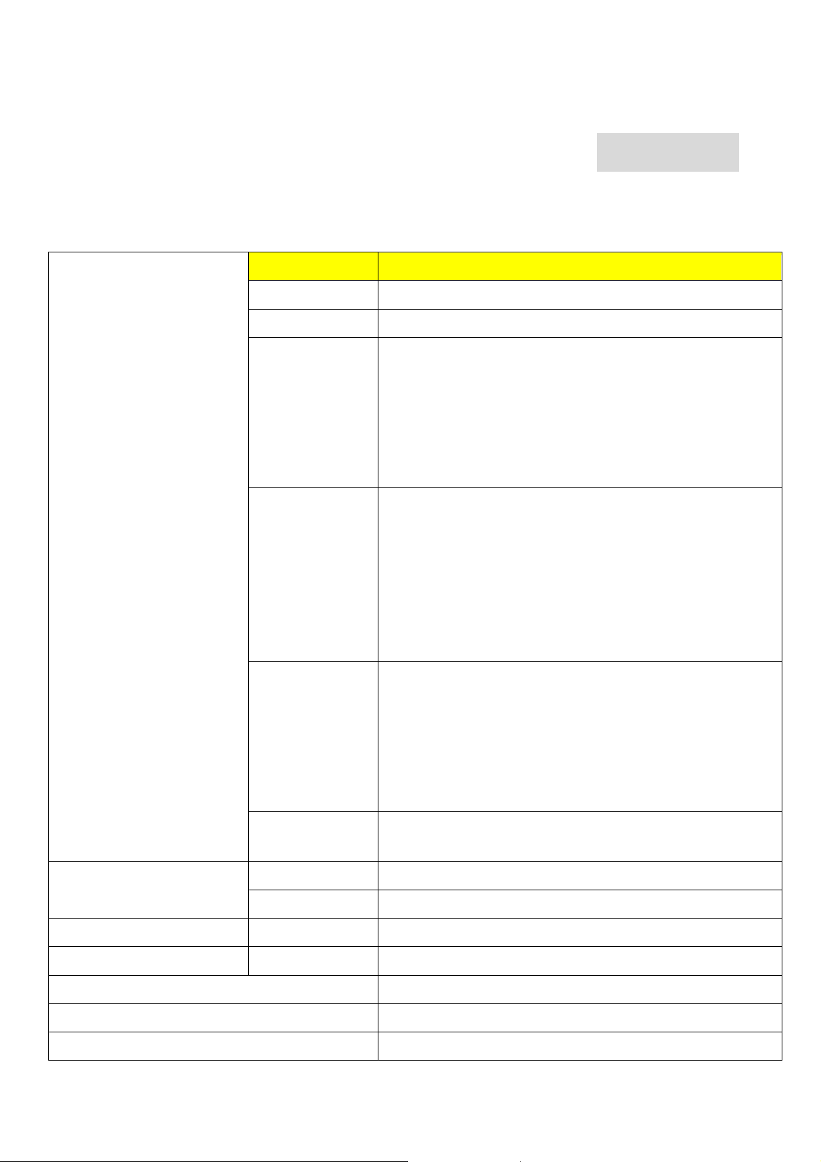
Driving system TFT Color LCD
Size 19"
Pixel pitch 0.294 mm
LCD Panel
Viewable angle
AU panel 8ms :70/60/70/70 degree(typ)
LG panel-8ms(TLB1/TLB4):70/70/70/70 degree(typ)
Samsung-8ms:75/60/75/75 degree(typ)
CPT panel-8ms:65/65/70/70 degree(typ)
HSDpanel-8ms:TBD
Brightness LG panel-8ms(TLB1/TLB4) :300 cd/m2(typ.)
AUO 8ms:270cd/m2(typ.)
Samsung 8ms: 300 cd/m2(typ.)
CPT 8ms:250 cd/m2(typ.)
HSD 12ms:250 cd/m2 (typ.)
Contrast Ratio
700:1 (AU M190EN04 V5 ,8ms)
550:1(LG LM190E03 TLB1/TLB4, 8ms)
700:1(Samsung TLM190EX-L01, 8ms)
700:1(CPT CLAA10EA05, 8ms)
600:1(HSD HSD190ME13-A02,8ms)
AU (V5) 8ms,LG (TLB1/TLB4) 8ms,Samsung 8 ms, CPT
Response time
Video R,G,B Analog,
Input
H-Frequency 31-81KHZ
V-Frequency 56-75HZ
Display Color 16.2 million Colors
Maximum Dot Clock ® 135MHz
Max Resolution 1280x1024@75HZ
Separate Sync H/V TTL
8ms,HSD 8 ms
- 9 -
Page 10
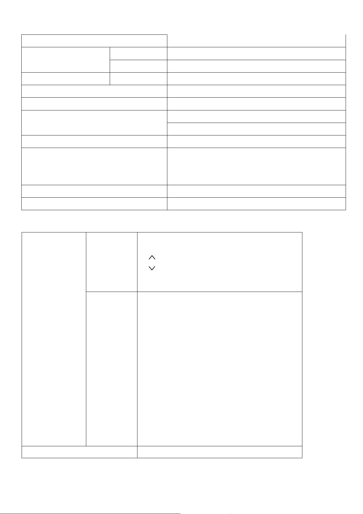
Plug & Play VESA DDC2B
ON Mode <40W
EPA ENERGY STAY
Audio output Rated Power 2.0W rms(Per channel)
Input Connector D-Sub, DVI-D
Input Video Signal Analog : 0.7Vp-p,75OHM
Screen Size (Active)
Power Source 90~264 Vac, 47~63HZ
Environmental
Considerations
Weight (N.W.) TBD
Dimension TBD
OFF Mode <2W
Horizontal : 337.9mm
Vertical : 270.3mm
Operating Temp : 5 to 40 degree ;
Storage Temp : -20 to 60 degree ;
Operating Humidity : 10% to 85%
External Controls
Switch * Power Switch
* MENU / EXIT
* / Volume
* / Volume
* AUTO / ENTER
* Contrast/brightness
* Focus
* Clock
* H.Position
* W.Position
* Language
* OSD Color temperature
* OSD Position & Timeout
* Auto Config
* Input
* Information
* Reset
* Exit
Regulatory Compliance cUL, FCC, TUV, CE, ISO13406-2
- 10 -
Page 11
Timings
The product has 26 memory modes in total. 16 modes are preset and 10 modes
are user definable.
MODE NO. 1 2 3 4
RESOLUTION
Dot clock(MHz)
f h
H-Total ( us ) 31.78(900dots) 31.778 (800 dots) 28.571(864 dots) 26.413 (832 dots)
H-Sync ( us ) 3.813(108dots) 3.813 (96 dots) 2.116 (64 dots) 1.270(40 dots)
H-B-P ( us ) 1.907(54dots) 1.907 (48 dots) 3.175 (96 dots) 4.064(128 dots)
H-Active ( us ) 25.42(720dots) 25.422 (640 dots) 21.164 (640 dots) 20.317(640 dots)
H-F-P ( us ) 0.636(18dots) 0.636 (16 dots) 2.116 (64 dots) 0.762(24 dots)
f v
V-Total (ms ) 14.27(449 lines) 16.683 (525 lines ) 15.000 (525 lines ) 13.735(520 lines)
V-Sync ( ms ) 0.064(2 lines) 0.064 (2 lines ) 0.086 (3 lines ) 0.079(3 lines)
V-B-P (ms ) 1.112(35 lines) 1.049 (33 lines ) 1.114 (39 lines ) 0.739(28 lines)
720 x 400 640 x 480 640x480 640 x 480
28.321 25.175 30.24 31.5
31.469kHz 31.469kHz 35.0kHz 37.861kHz
70Hz(70.087) 60Hz (59.940) 66.7 HZ (66.667)
72.809Hz
V-Active ( ms ) 12.71(400 lines) 15.253 (480 lines ) 13.714 (480 lines ) 12.678(480 lines)
V-F-P ( ms ) 0.384(12 lines) 0.317 ( 10 lines) 0.086 (3 lines )
SYNC. H/V -/+ - / - +/+ -/POLARITY Or -/-
SEP . SYNC Y Y Y Y
MODE NO. 5 6 7 8
RESOLUTION
Dot clock(MHz)
f h
H-Total ( us ) 26.667(840 dots) 28.44(1024 dots) 26.40 (1056
H-Sync ( us ) 2.032 (64 dots)
640 x 480 800 x 600 800 x 600 800 x 600
31.5 36 40 49.5
37.500kHz 35.16kHz 37.879kHz 46.875kHz
dots)
2.00(72 dots) 3.200 (128 dots) 1.616 (80 dots)
0.237(9 lines)
21.333 (1056dots)
- 11 -
Page 12
H-B-P ( us ) 3.810 (120 dots) 3.56(128 dots) 2.200 ( 88 dots) 3.232 (160 dots)
H-Active ( us ) 20.317 (640 dots) 22.22(800 dots) 20.00 ( 800 dots) 16.162 (800 dots)
H-F-P ( us ) 0.508 (16 dots)
0.67(24 dots) 1.000 (40 dots) 0.323 (16 dots)
f v
75Hz (75) 56.25 60Hz (60.316) 75Hz (75.000)
V-Total (ms ) 13.333 (500 lines) 17.78(625 lines) 16.58 (628 lines) 13.333 (625lines)
V-Sync ( ms ) 0.080 (3 lines) 0.06(2 lines) 0.106 (4 lines) 0.064 (3 lines)
V-B-P (ms ) 0.427 (16 lines) 0.63(22 lines) 0.607 (23 lines) 0.448 (21 lines)
V-Active ( ms ) 12.80 (480 lines) 17.07(600 lines) 15.84 (600 lines) 12.80 (600lines)
V-F-P ( ms ) 0.027 ( 1 line ) 0.03( 1 line) 0.026 (1 line ) 0.021 (1 line )
SYNC. H/V - / - +/+ + / + + / +
POLARITY
SEP . SYNC Y Y Y Y
MODE NO. 9 10 11 12
RESOLUTION
800 x 600 832 x 624 1024 x 768 1024 x 768
Dot clock(MHz)
50 57.283 65 75
f h
48.077kHz 49.72kHz 48.363kHz 56.48kHz
H-Total ( us ) 20.80 (1040dots) 20.11(1152 dots) 20.677(1344 dots) 17.71(1328 dots)
H-Sync ( us ) 2.400 ( 120 dots) 1.12(64 dots) 2.092(136 dots) 1.81(136 dots)
H-B-P ( us ) 1.280 (64 dots) 3.91(224 dots) 2.462(160 dots) 1.92(144 dots)
H-Active ( us ) 16.00 (800 dots) 14.52( 832 dots ) 15.754(1024 dots) 13.65(1024 dots)
H-F-P ( us ) 1.120 (56 dots) 0.56(32 dots ) 0.369(24 dots) 0.32(24 dots)
f v
72Hz (72.188) 74.55Hz 60.004Hz 70.07Hz
V-Total (ms ) 13.85 (666 lines) 13.41(667 lines) 16.666(806 lines) 14.27(806 lines)
V-Sync ( ms ) 0.125 (6 lines) 0.06(3 lines) 0.124(6 lines) 0.11(6 lines)
V-B-P (ms ) 0.478 (23 lines) 0.78(39 lines) 0.600(29 lines)
0.51(29 lines)
V-Active ( ms ) 12.48 (600 lines) 12.55 (624 lines) 15.880(768 lines) 13.60(768 lines)
V-F-P ( ms ) 0.770 ( 37
0.02(1 line) 0.062(3 lines) 0.05(3 lines)
line )
SYNC. H/V + / + +/+ -/- -/POLARITY
SEP . SYNC Y Y Y Y
- 12 -
Page 13
D
E
MODE NO. 13 14 15 16
RESOLUTION
Dot clock(MHz)
f h
H-Total ( us ) 16.66(1312 dots) 15.630 (1688 dots) 12.504 (1688 dots) 14.815(1600 dots)
H-Sync ( us ) 1.22 (96 dots) 1.037 (112 dots) 1.067 (144 dots) 1.185(128 dots)
H-B-P ( us ) 2.23 (176 dots) 2.296 (248 dots) 1.837 (248 dots) 2.370(256 dots)
H-Active ( us ) 13.00 (1024 dots) 11.852 (1280 dots) 9.481 (1280dots) 10.667(1152 dots)
H-F-P ( us ) 0.20 (16 dots) 0.444 (48 dots) 0.119 (16 dots) 0.593(64 dots)
f v
V-Total (ms ) 13.33 (800 lines) 16.661 (1066
V-Sync ( ms ) 0.05 (3 lines) 0.047 ( 3 lines) 0.038 (3 lines) 0.044(3 lines)
1024 x 768 1280 x 1024 1280 x 1024 1152 x 864
78.75 108 135 108
60.02kHz 63.981kHz 79.976KHz 67.5 KHz
75.03Hz 60.020Hz 75.025 Hz 75.06 Hz
lines)
13.329 (1066
lines)
13.333(900 lines)
V-B-P (ms ) 0.47 (28 lines) 0.594 ( 38 lines) 0.475 (38 lines) 0.474(32 lines)
V-Active ( ms ) 12.80 (768 lines) 16.005 (1024
lines)
V-F-P ( ms ) 0.02 (1 lines) 0.016 (1 line ) 0.013 (1 lines) 0.015(1 lines)
SYNC. H/V -/- +/+ +/+ +/+
POLARITY
SEP . SYNC Y Y Y Y
A
B : H- Sync width P : V- Sync width
C : H- Back porch Q :.V- Back porch
: H-Total
: H- Video width R : V- Video width
: H- Front porch S :.V- Front porch
O
: V-Total
12.804(1024 lines) 12.800(864 lines)
- 13 -
Page 14
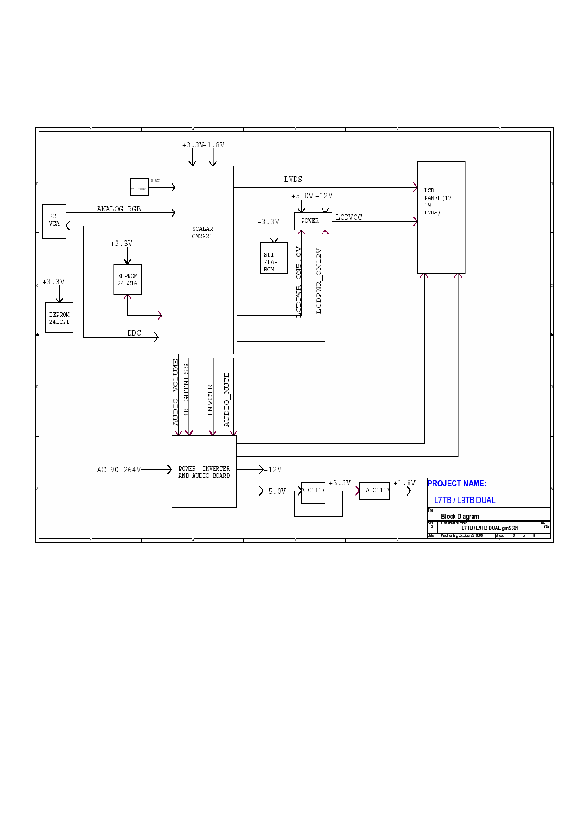
Monitor Block Diagram
- 14 -
Page 15
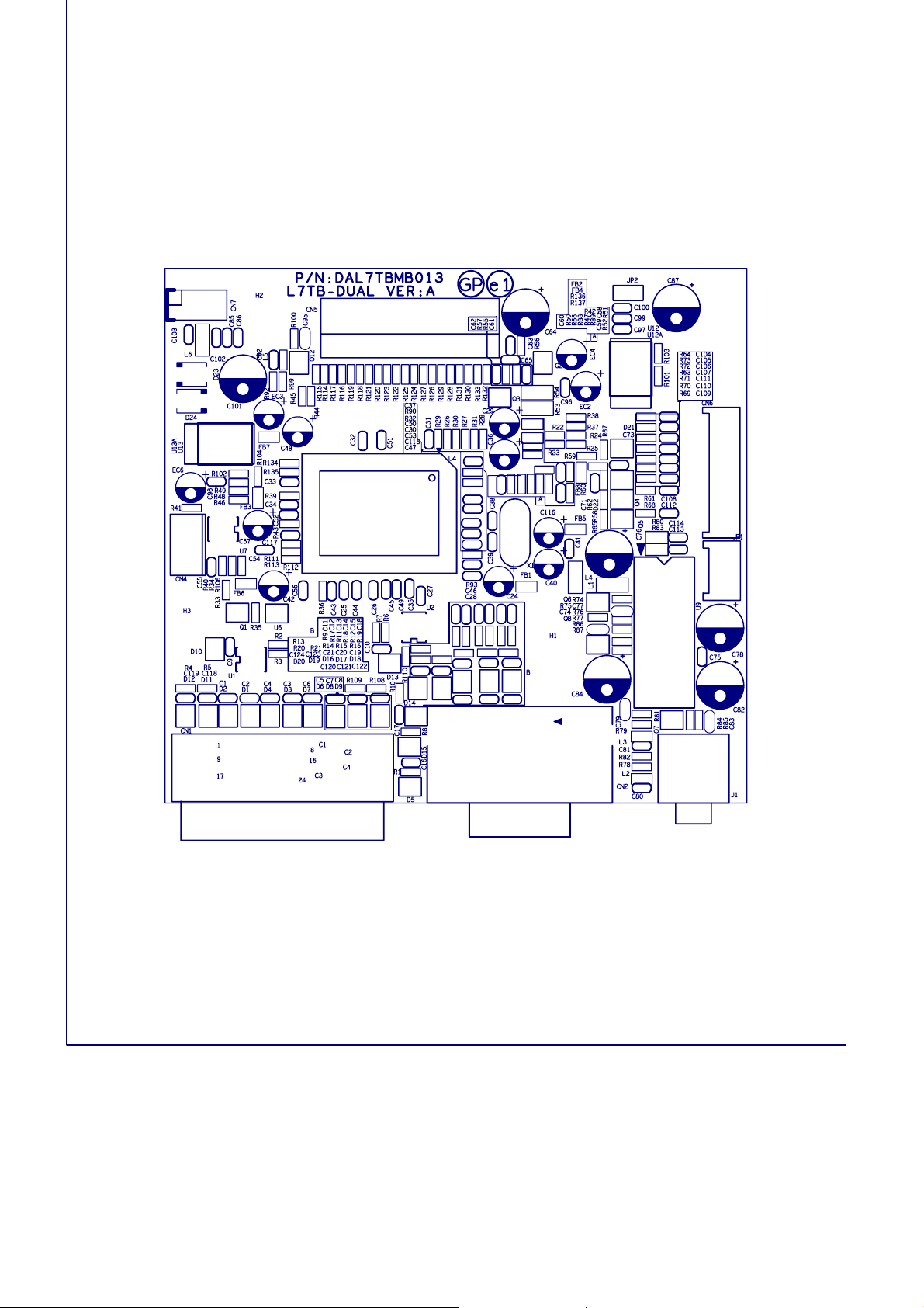
Page 16
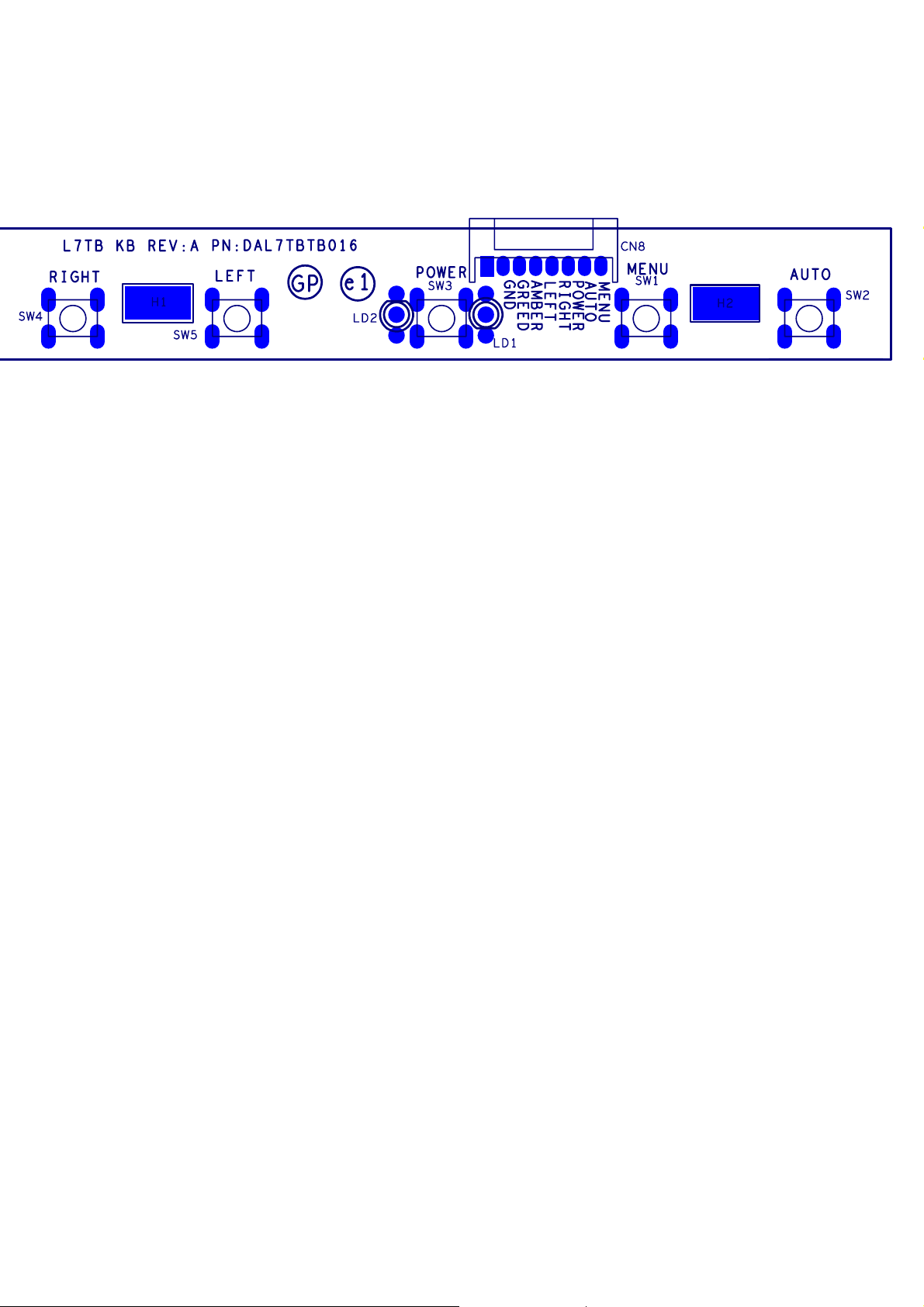
Page 17
OPERATING INSTRUCTIONS
is inactive, press once, then press the buttons marked or
is inactive, press once, then press the buttons marked or
Front Panel Definition
This Section defines the front panel User Interface for Led Indictor and Key function.
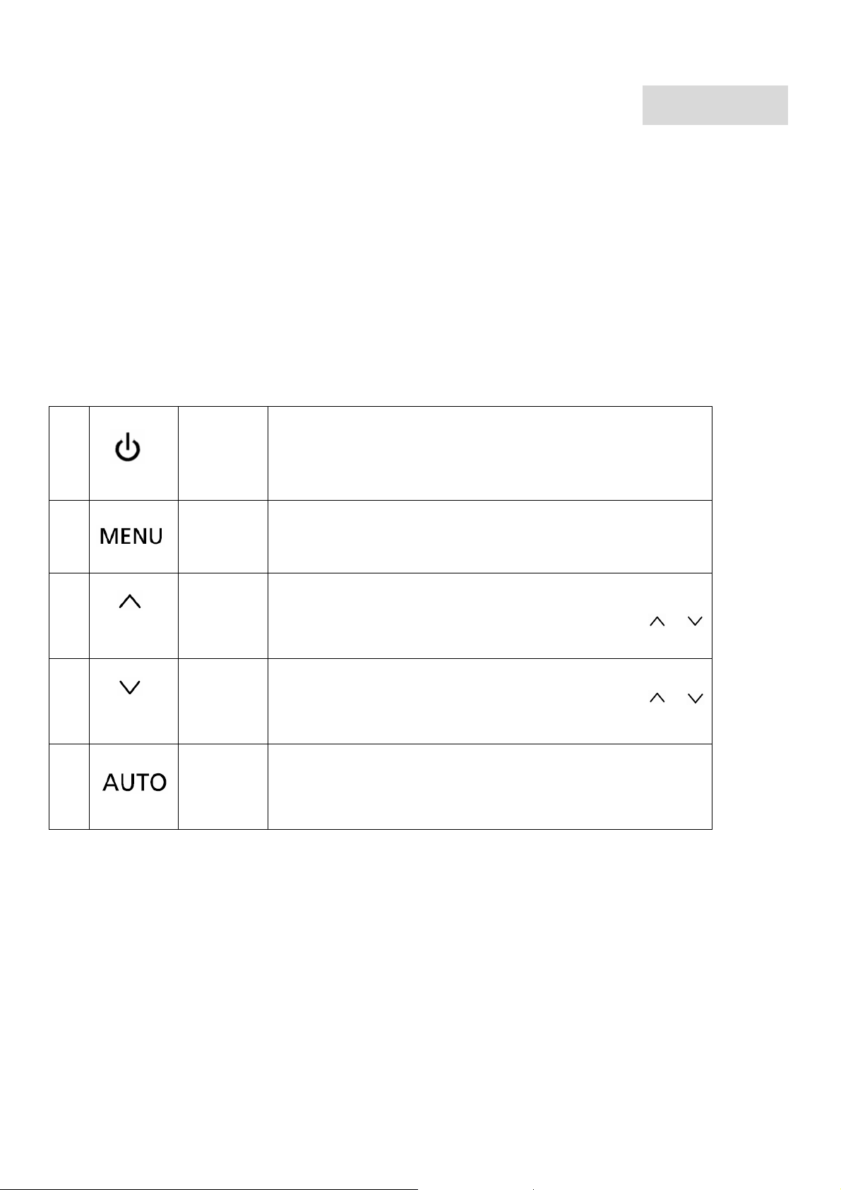
Key Definition:
There are five keys defined in this system and described bellows.
External Controls
Chapter 2
1
?
2
?
3
?
4
?
5
?
POWER
OSD
Function
UP/ PLUS
DOWN /
MINUS
AUTO
Power on/off
Blue: power on
Orange: in sleep mode
Press to view OSD.
Press again to exit a selection in OSD.
If OSD is active, press to select or adjust OSD options. If OSD
to adjust the volume.
If OSD is active, press to select or adjust OSD options. If OSD
to adjust the volume.
If OSD is active, press to enter a selection in OSD. If OSD is
inactive, press and the monitor will automatically optimize the
position, focus and clock of your display.
- 19 -
Page 18
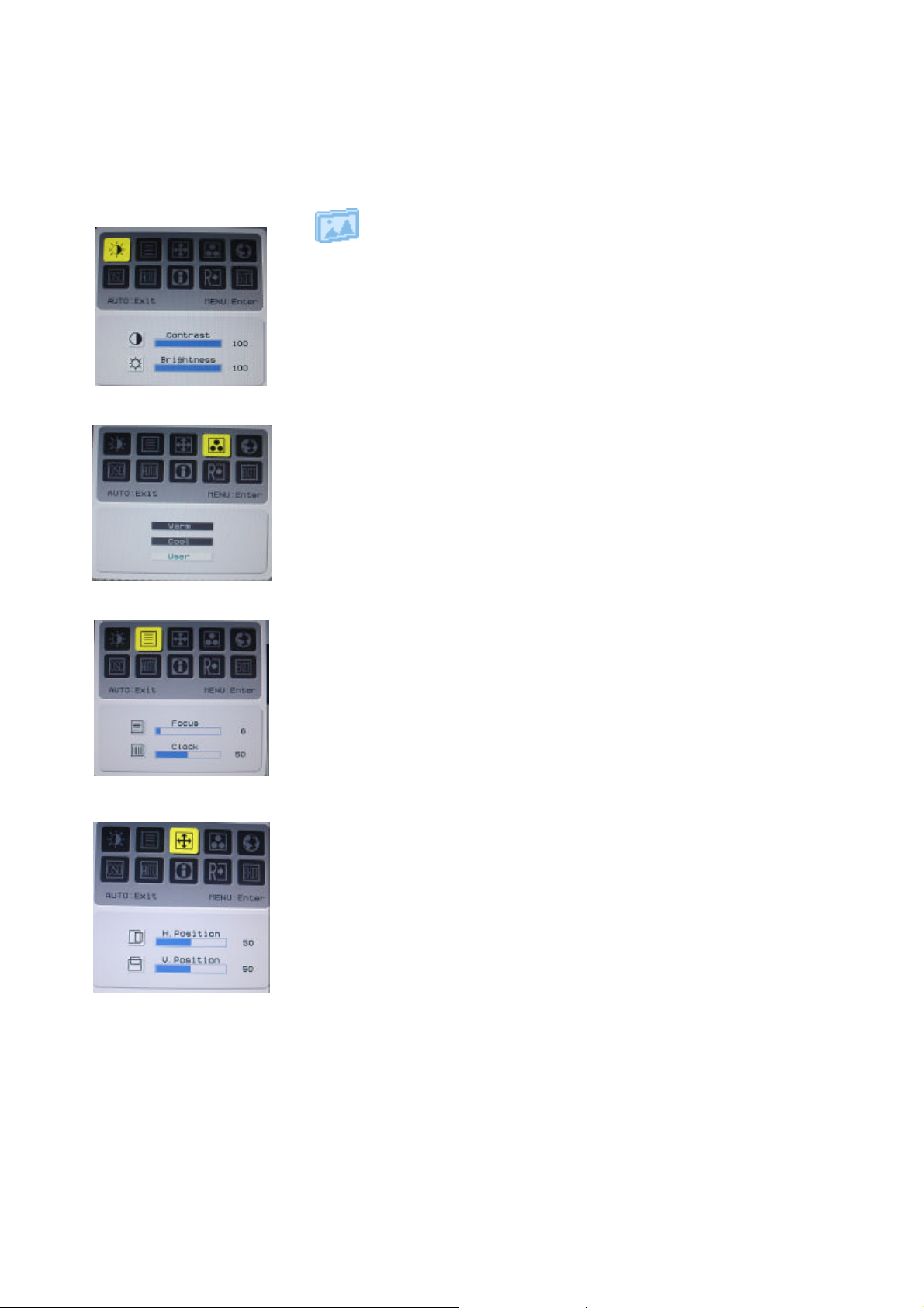
OSD Menu
Picture
Brightness:
This adjusts the brightness of the picture on the screen.
Contrast:
This adjusts dark and light shades of color relative to each other to
achieve a comfortable contrast.
Color temp. :
There are three ways of adjusting color:
Warm (Reddish white)
Cool (Bluish white)
User : You can adjust the colors red, green and blue to the intensity
you desire.
Focus:
This removes any horizontal distortion and makes the picture clear
and sharp.
Clock:
If there are any vertical stripes seen on the background of the screen
this renders them less noticeable by minimizing their size. It also
changes the size of the horizontal screen.
H-Position:
This adjusts the horizontal screen position.
V-Position:
This adjusts the vertical screen position.
- 20 -
Page 19
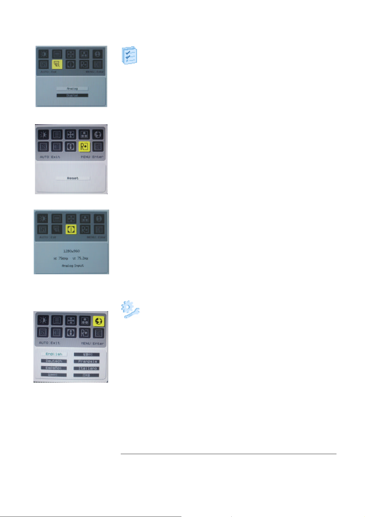
Option
Auto Config. :
System choose signal “Analog or Digital”
Reset:
Recall to default settings.
Information:
This shows brief information on the screen.
Setting
Language:
Select the OSD menu language from
English, French, German, Italian, Spanish, Simplified Chinese,
Traditional Chinese, Japanese and Russian.
OSD H. Position
OSD V. Position
OSD Time-out
This changes the position of the OSD window on the screen and staying
time.
- 21 -
Page 20
LED Definition
The system equips one dual color (blue/amber) led to indict system status and defined as bellows :
System Status LED Color
System in normal operation mode Green
Amber
System in power-saving mode
System in power-off mode Dark
LOGO :
When the monitor is power on, the LOGO will be showed in the center, and disappear slowly.
HOW TO OPTIMIZE THE DOS-MODE
Plug and play
Plug & play DDC2B feature
This monitor is equipped with VESA DDC2B capabilities according to the VESA DDC STANDARD. It
allows the monitor to inform the host system of its identity and, depending on the level of DDC used,
communicate additional information about its display capabilities. The communication channel is defined in
two levels, DDC2B.
The DDC2B is a bi-directional data channel based on the I2C protocol. The host can request EDID
information over the DDC2B channel.
- 22 -
Page 21

THIS MONITOR WILL APPEAR TO BE NON-FUNCTIONAL IF THERE IS NO VIDEO INPUT
SIGNAL. IN ORDER FOR THIS MONITOR TO OPERATE PROPERLY, THERE MUST BE A
VIDEO INPUT SIGNAL.
This monitor meets the Green monitor standards as set by the Video Electronics Standards
Association(VESA) and/or the United States Environmental Protection Agency (EPA) and The Swedish
Confederation Employees (NUTEK). This feature is designed to conserve electrical energy by reducing
power consumption when there is no video-input signal present. When there is no video input signal this
monitor, following a time-out period, will automatically switch to an OFF mode. This reduces the monitor’s
internal power supply consumption. After the video input signal is restored, full power is restored and the
display is automatically redrawn. The appearance is similar to a “Screen Saver” feature except the display is
completely off. The display is restored by pressing a key on the keyboard, or clicking the mouse.
USING THE RIGHT POWER CORD
The accessory power cord for the Northern American region is the wallet plug with NEMA 5-15 style and is
UL listed and CSA labeled. The voltage rating for the power cord shall be 125 volt AC.
Supplied with units intended for connection to power outlet of personal computer: Please use a cord set
consisting of a minimum No. 18 AWG, type SJT or SVT three conductors flexible cord. One end terminates
with a grounding type attachment plug, rated 10A, 250V,CEE-22 male configuration. The other end
terminates with a molded-on type connector body, rated 10A, 250V, having standard CEE-22 female
configuration.
Please note that power supply card needs to use VDE 0602, 0625, 0821 approval power cord in European
counties.
- 23 -
Page 22
Chapter 3
Machine assembly
This chapter contains step-by-step procedures on how to assemble the monitor for maintenance and
trouble shooting
NOTE : 1. The screws for the different components vary in size. During the disassembly process, group the
screws with the corresponding to avoid mismatch when putting back the components.
2. Note : The monitor surface is susceptible to scratching! Therefore, lay the monitor on a soft
surface when mounting or removing the base.
3. Wear gloves.
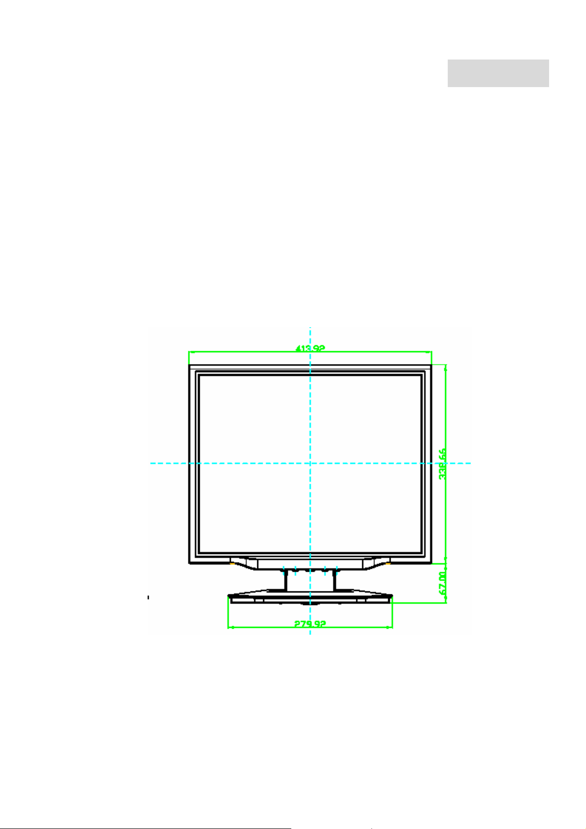
Front View : ( unit : mm )
- 24 -
Page 23
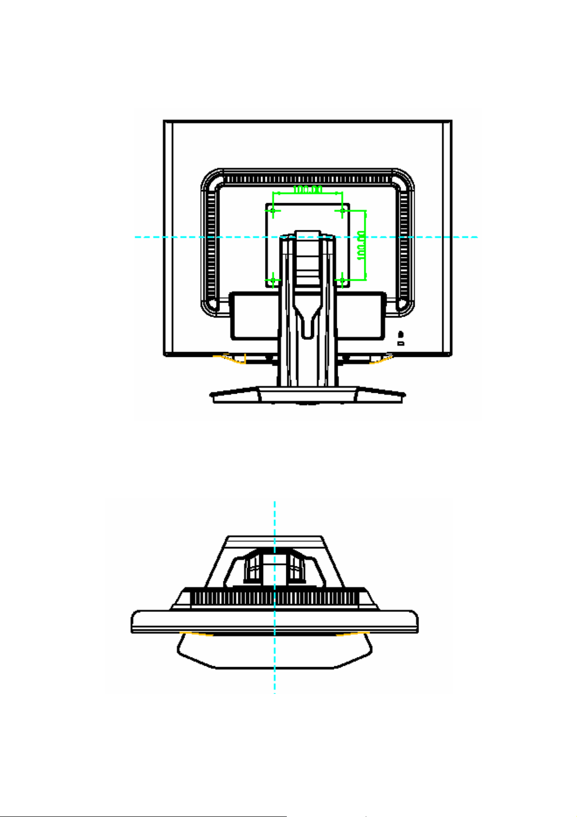
Real View :
Top View :
- 25 -
Page 24
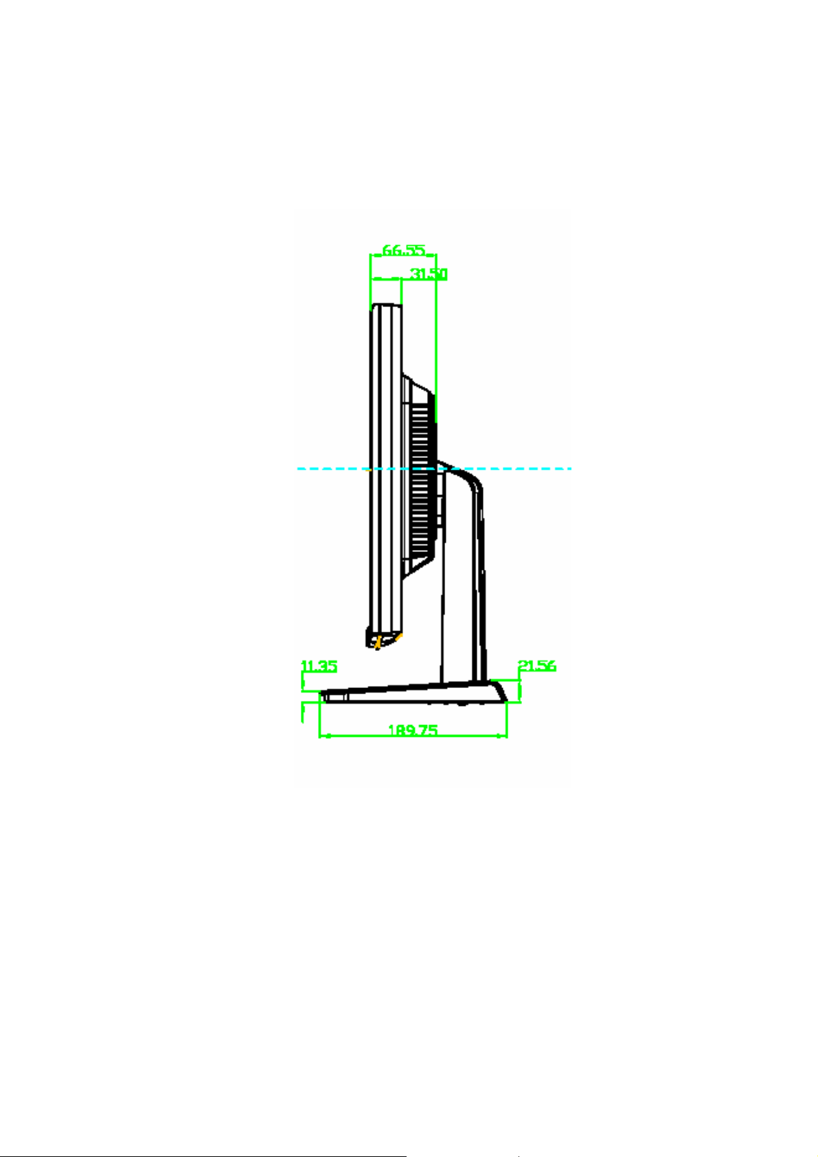
Side View : ( unit : mm )
Exploded view
- 26 -
Page 25
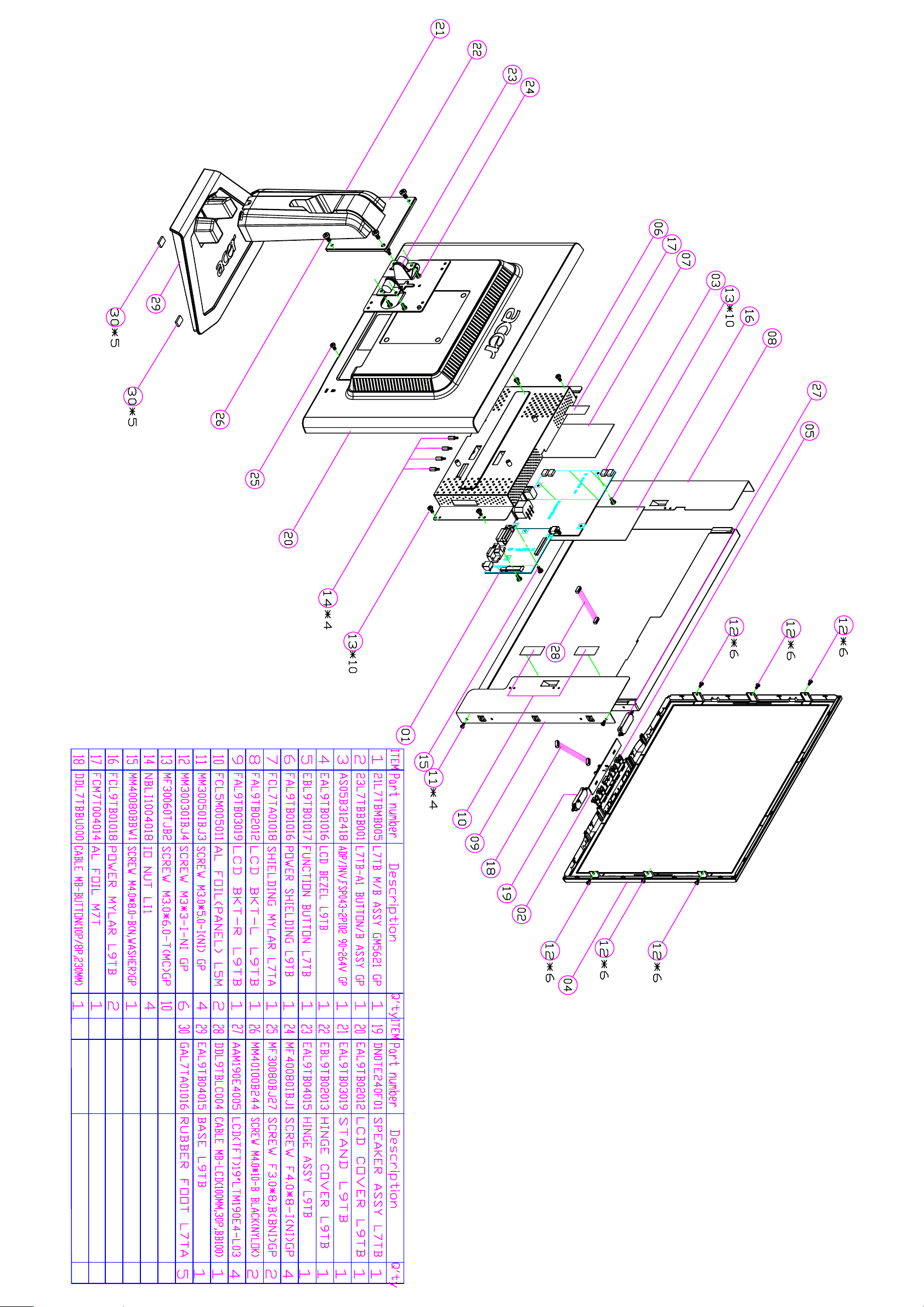
Page 26
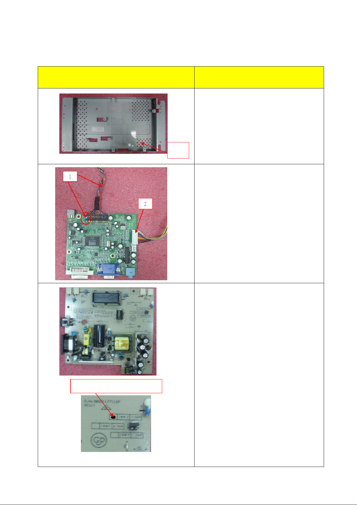
Assembly process
Picture Description
1
1. [GET PCB SHIELD AND PUT IT IN THE
MIDDLE OF CONVEYER]
1. [GET M/B AND LCD CABLE,THEN
INSERT LCD CABLE IN M/B
CONNECTOR]
2. [GET BUTTON CABLE,THEN INSERT IT
INTO M/B CONNECTOR]
Jumper value set as 7.5mA
5
1. GET POWER/B AND INSERT JUMPER
IN THE APPOINTED PLACE OF JP10 AT
2. GET AGGLUTINANT TO CONNECT THE
JUMPER AND POWER/B
3. MARK DOT IN THE PANE MARK OF
POWER/B AS PICTURE SHOWS
- 27 -
Page 27
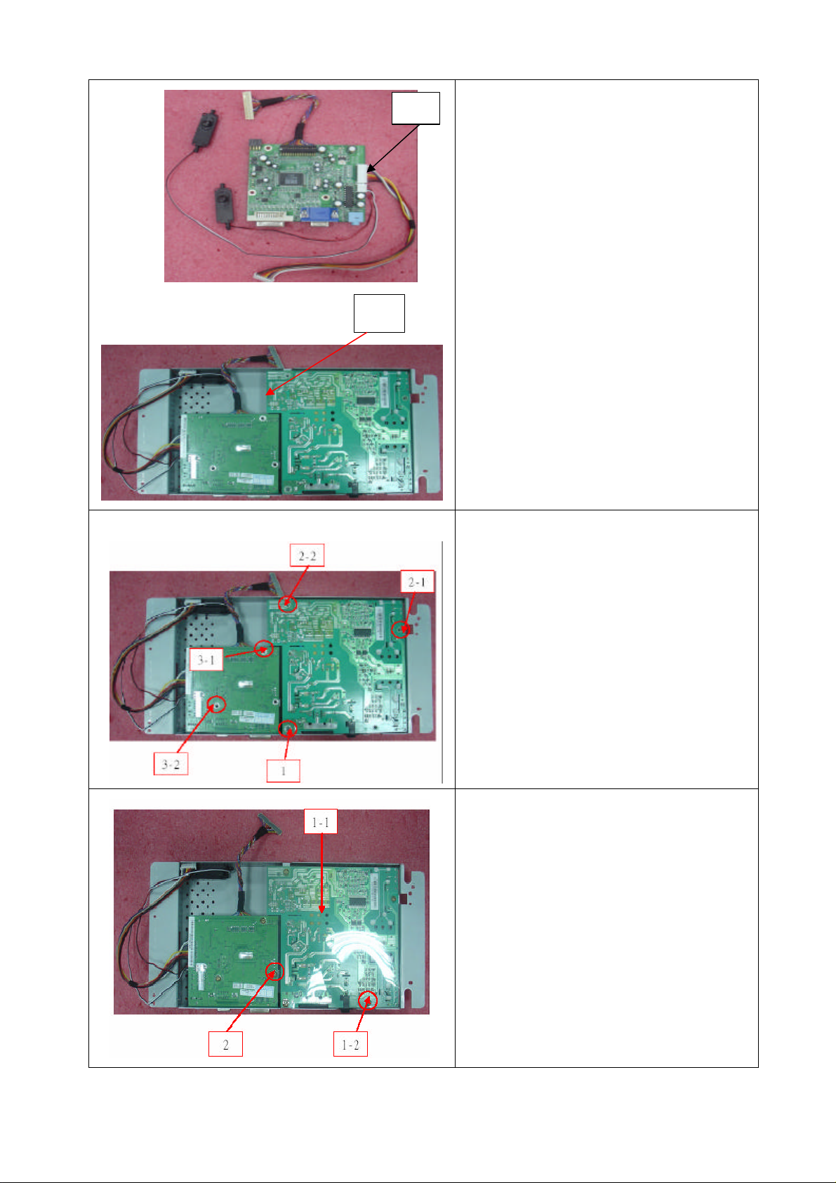
1
1. INSERT SPEAKER CABLE IN M/B
2
CONNECTOR
2. GET M/B AND ASSEMBLE IT WITH
POWER/B,THEN ASSEMBLE THEM IN
PCB SHIELD
1. FASTEN 1*PCS SCREW(M 4*8-B) IN P/B
2. FASTEN 2*PCS SCREW(M 3*6-T) IN P/B
3. FASTEN 2*PCS SCREW(M 3*6-T) IN
M/B
1. FETCH POWER/B MYLAR PUT IT ON
SHIELD AND FASTEN 1*PCS SCREW(M
3*6-T
2. FASTEN 1*PCS SCREW(M 3*6-T) IN M/B
3. GET THE SHIELD AT FRONTAGE OF
THE CONVEYER
- 28 -
Page 28
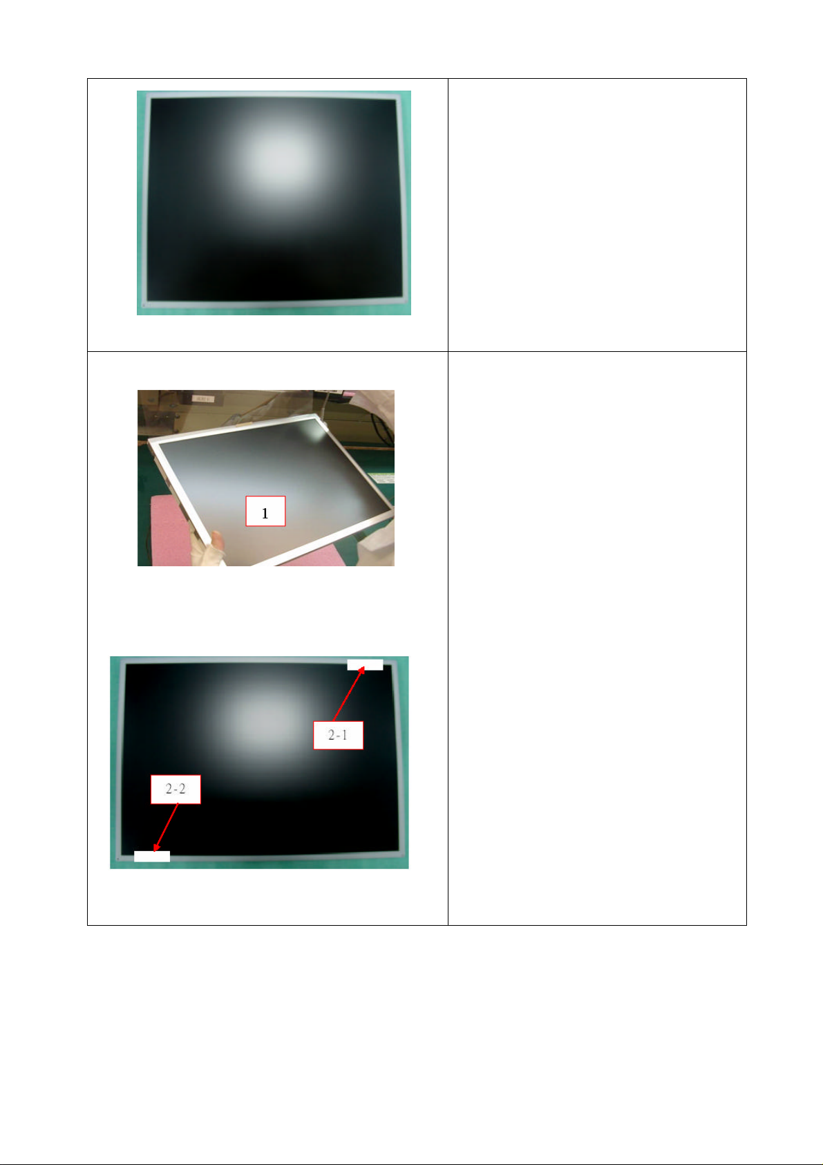
1. GET THE SHIELD AT FRONTAGE
OF THE CONVEYER
2. GET PANEL AND PUT IT ON THE
CONVEYER, THEN TEAR OFF THE
INCOMING TAPE
1. UNCOVER PANEL PROTECTIVE FILM
AND INSPECT IF PANEL IS DIRTY OR
SCRATCHED
2. PASTE TYPE ON THE PROTECTIVE
FILM TO FASTEN IT
3. TURN LCD,TEAR OFF INCOMING TYPE
- 29 -
Page 29
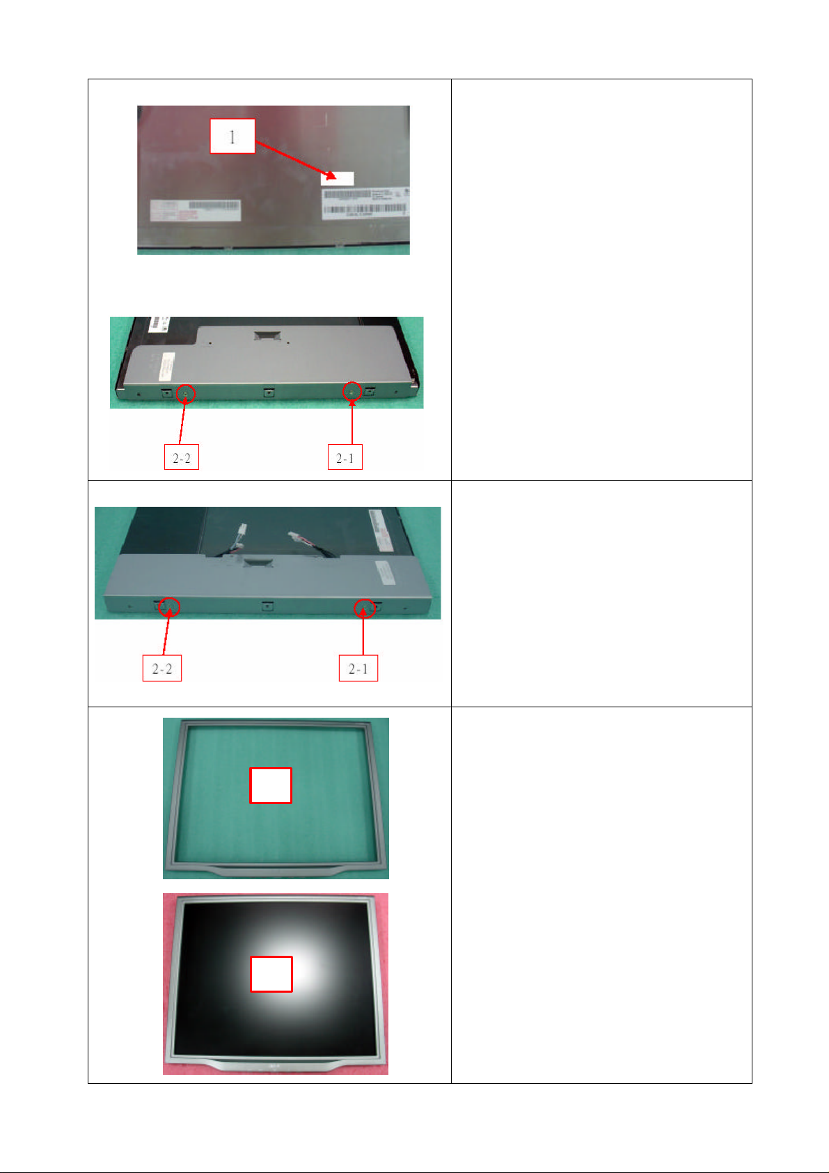
1. FETCH TRAVEL CARD, TEAR OFF
1*PCS S/N FROM TRAVEL CARD AND
PASTE IT ON THE PANEL BACK,THEN
SCAN S/N AND PANEL CODE
2. GET LEFT BKT AND LOCK 2*PCS
SCREW(M3*5-I) TO FASTEN IT AND
PANEL
1. GET RIGHT BKT AND LOCK 2*PCS
SCREW(M3*5-I) TO FASTEN IT AND
PANEL
2. TURN LCD AND TEAR OFF
PROTECTIVE FILM
1
2
1. GET BEZEL AND CHECK ITS
APPEARANCE
2. ASSEMBLE BEZEL ON PANEL,THEN
PASTE TYPE TO FASTEN PROTECTIVE
FILM ON THE BEZEL
3. TURN LCD
- 30 -
Page 30
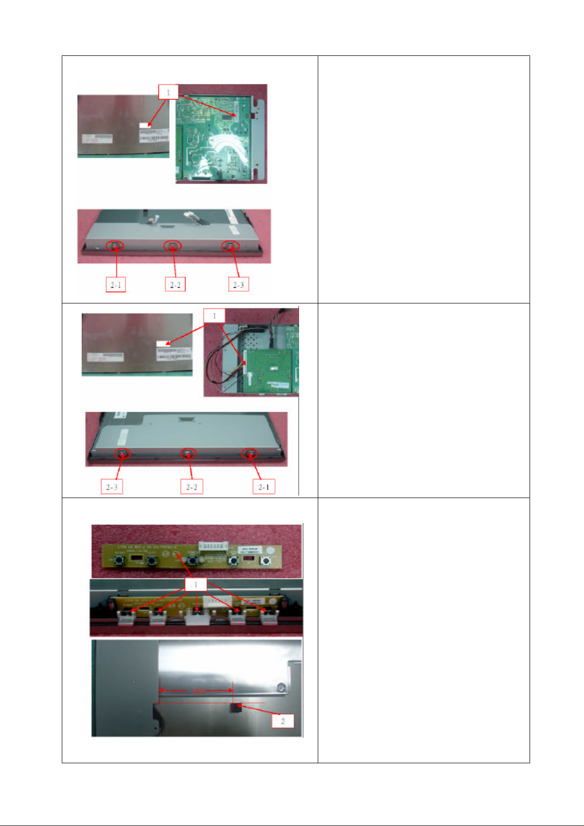
1. SCAN S/N AND POWER CODE
2. FASTEN BKT AND BEZEL IN THE RIGHT
SIDE WITH SCREW 3*PCS
1. SCAN S/N AND M/B CODE
2. FASTEN BKT AND BEZEL IN THE LEFT
SIDE WITH SCREW 3*PCS
3. TURN LCD
1. FETCH BUTTON/B AND INSERT IT INTO
BEZEL
2. STICK 1*PCS RUBBER AT THE
APPOINTED PLACE
- 31 -
Page 31
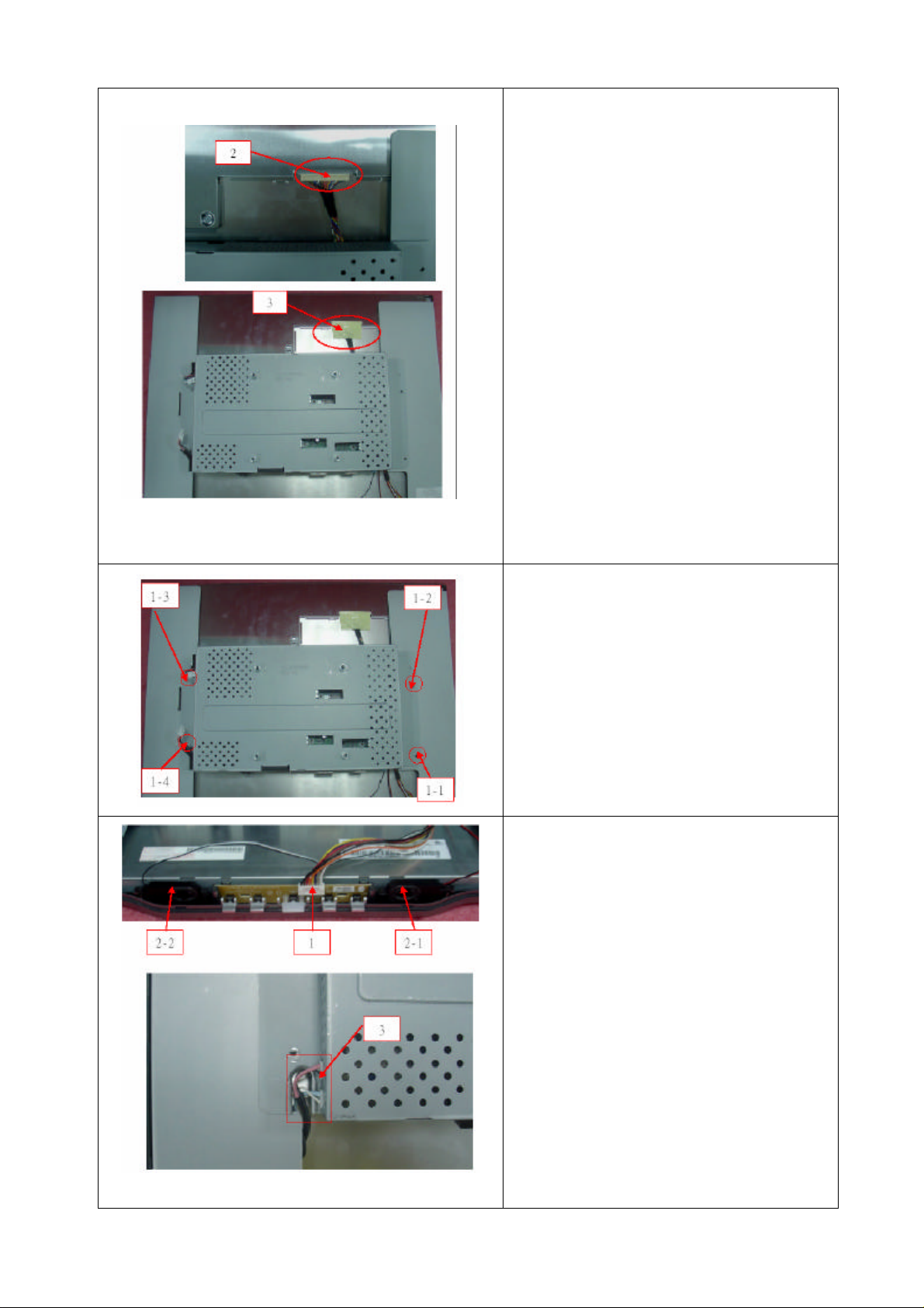
1. GET SHIELD ON THE BKT R/L
2. INSERT LCD CABLE INTO PANEL
CONNECTOR
3. STICK 1*PCS YELLOW TAPE TO
FASTEN LCD CABLE
4. TRIM WIRES AND ASSEMBLE
SHIELDING IN RIGHT POSITION
1. LOCK 4*PCS SCREW(M3*6-T) TO
FASTEN PCB SHIELD
1. INSERT BUTTON CABLE INTO BUTTON
2. PUT THE SPEAKER AT THE
APPOINTED PLACE
3. INSERT NETHER CCFT CABLE IN
INVERTER CABLE
- 32 -
Page 32
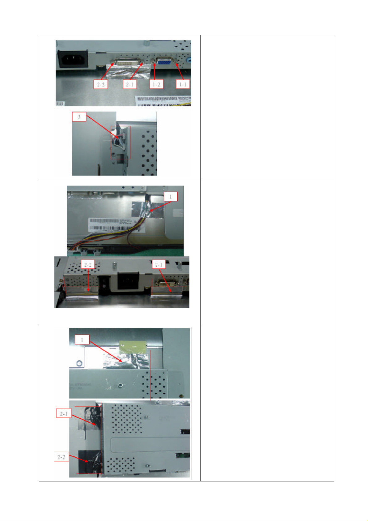
1. FASTEN 2*PCS IO-NUT IN THE VGA
JOINT
2. FASTEN 2*PCS IO-NUT IN THE M/B
JOINT
3. INSERT CCFT CABLE IN POWER/B
1. STICK AL FOIL AT THE APPOINTED
PLACE TO FASTEN THE CABLE
2. STICK 2*PCS AL FOIL AT THE
APPOINTED PLACE
1. STICK 1*PCS AL FOIL AT THE
APPOINTED PLACE
2. STICK 2*PCS AL FOIL AT CCFT
- 33 -
Page 33
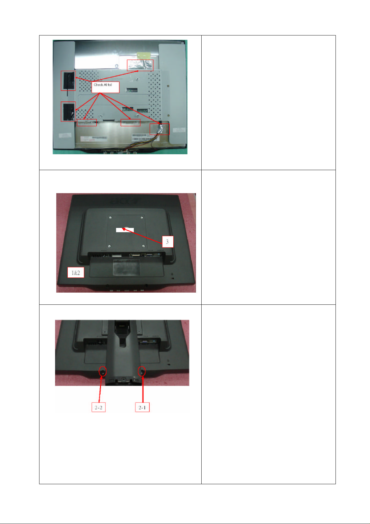
1. CHECK THE Q’TY AND LOCATION OF
AL FOIL
1. GET LCD COVER AND INSPECT ITS
APPEARANCE
2. ASSEMBLE LCD COVER TO BEZEL
3. STICK 1*PCS TAPE AT THE APPOINTED
PLACE
1. FETCH TRAVEL CARD, TEAR OFF
1*PCS APPOINTED S/N FROM TRAVEL
CARD AND PASTE IT ON THE COVER
2. LOCK 2*PCS SCREW (F3*8-B) TO
FASTEN BEZEL AND LCD COVER
3. GET STAND NECK AND INSPECT IF IT
IS DIRTY AND SCRATCHED,THEN PUT
IT IN THE CONVEYER
- 34 -
Page 34
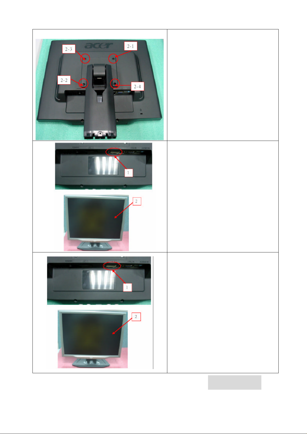
1. AT FIRST CHECK IF 2*PCS SCREW IN
THE COVER IS LOST
2. LOCK 4*PCS SCREW (M4*10-B) TO
FASTEN STAND NECK
1. INSERT VGA CABLE INTO VGA
CONNECTOR AND INSERT POWER
CORD INTO POWER CONNECTOR
2. GET BASE FIXTRUE AND ASSEMBLE IT
TO STAND NECK.
1. INSERT DVI CABLE INTO DVI
CONNECTOR AND INSERT POWER
CORD INTO POWER CONNECTOR
2. STAND UP THE MONITOR AND STICK
TRAVALCARD AT LEFT DOWNSIDE OF
MONITOR
- 35 -
Chapter 4
Page 35
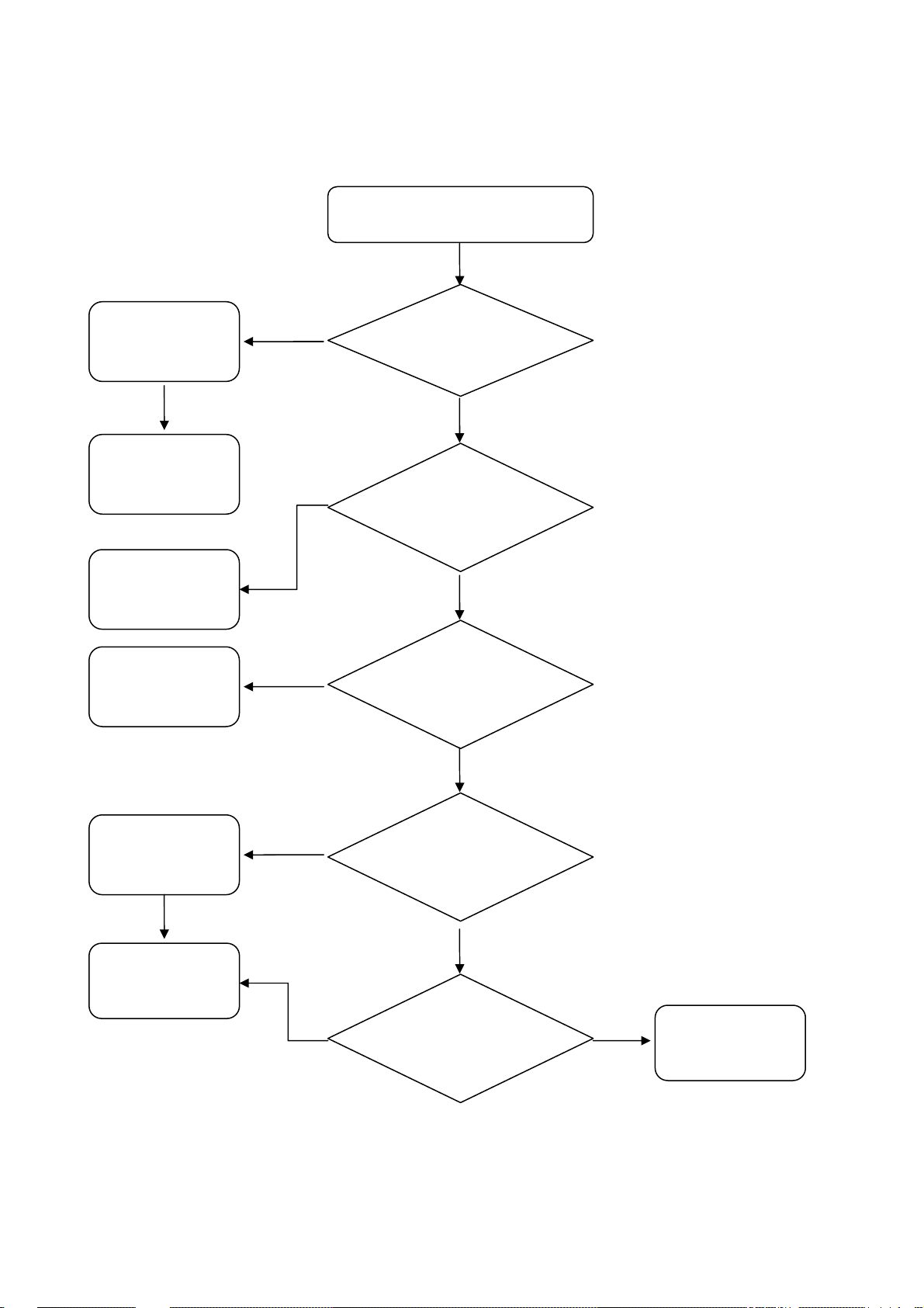
Trouble Shooting
V
1. No Power
No Power
Change
Power Board
No
Check Short Of
Main Board
Change
U13,U12
Change X1 or
U4
NO
NO
NO
Check CN7
+12V and +5
Yes
Check U13=1.8V
U12=3.3V
Yes
Check
X1=14.318MHz
Change U7 or
U4
Change U7
RUN Software
ISP
NO
Yes
Yes
Check U7 Pin
1,2,5,6 Clock
Yes
Check Key
Board
NO
Change Key
Board
Page 36
2. Missing Color
Missing Color
Change
Cable
Change
R9,R11,R12,
U4
Change U4
or CN5 Cable
or Panel
NO
NO
NO
Check VGA or
DVI Cable
Yes
Check
R9,R11,R12
Yes
Check CN5
LVDS Signal
Adjustment
R/G/B Color
Yes
NO Yes
Check OSD
R/G/B Gain
Change
Panel
Page 37
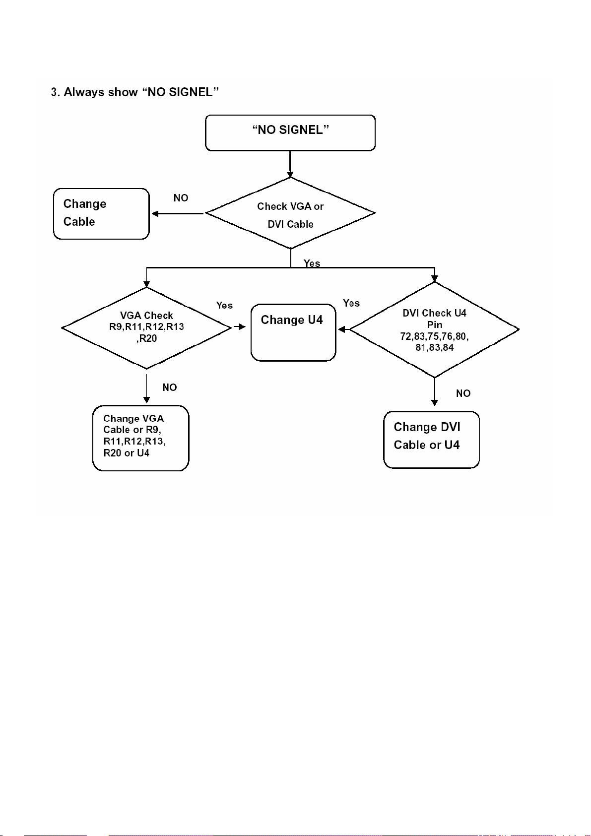
- 38-
Page 38
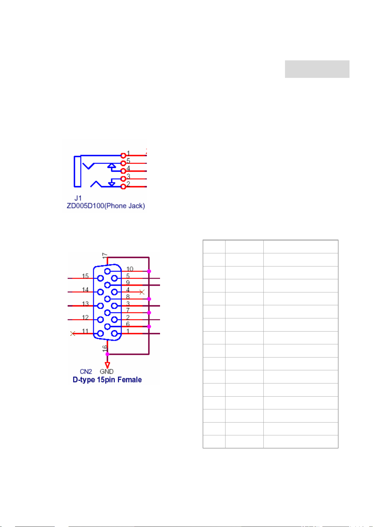
Connector Information
PI
MNEM
SIGNAL
1 RV
Red Video
2 GV
Green Video
3 BV
Blue Video
4 NC
None
5
GND
Ground(DDC return)
6 RG
Red GND
7 GG
Green GND
8 BG
Blue GND
9
+5V
+ 5V (for DDC)
10 SG
Sync GND
11 NC
None
12
SDA
DDC Data
13 HS
Horizontal Sync
14 VS
Vertical Sync
15
SCL
DDC Clock
Phonejack stereo
PIN1. AC power cord : CEE22 typed connector
PIN2. Audio cable
PIN3. Audio : Line-in receptacle
The PIN assignment of the 15 pin mini D-SUB connector / cable is as follows:
Chapter 5
- 39-
Page 39
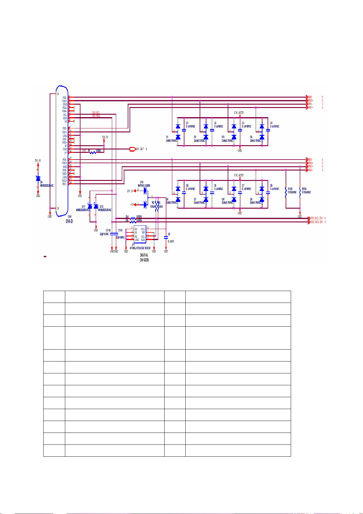
The PIN assignment of the 24 pin DVI D connector / cable is as follows:
PIN Signal PIN Signal
1 TMDS data2- 13 NC
2 TMDS data2+ 14 +5V
3 TMDS data2 shield 15 Ground (return for +5 V and H/V
sync)
4 NC 16 Hot plug detect
5 NC 17 TMDS data06 DDC clock 18 TMDS data0+
7 DDC data 19 TMDS data0 shield
8 Not connected 20 NC
9 TMDS data1- 21 NC
10 TMDS data1+ 22 TMDS clock shield
11 TMDS data1 shield 23 TMDS clock+
12 NC 24 TMDS clock-
- 40-
Page 40

Chapter 6
FRU (Field Replaceable Unit) list
This chapter gives you the FRU (Field Replaceable Unit) listing in global configurations of AL1511.
Refer to this chapter whenever ordering for parts to repair or for RMA (Return Merchandise
Authorization).
NOTE : Please note WHEN ORDERING FRU PARTS, that you should check the most up-to-date
information available on your regional web or channel(http://aicsl.acer.com.tw/spl/). For whatever
reasons a part number change is made, it will not be noted in the printed Service Guide. For
ACER-AUTHORIZED CERVICE PROVIDERS, your Acer office may have a DIFFERENT part
number code to those given in the FRU list of this printed Service Guide. You MUST use the local
FRU list provided by your regional Acer office to order FRU parts repair and service of customer
machines.
NOTE: To scrap or to return the defective parts, you should follow the local government ordinance or
regulations on how best to dispose it, or follow the rules set by your regional Acer office on how to
return it.
- 41 -
Page 41
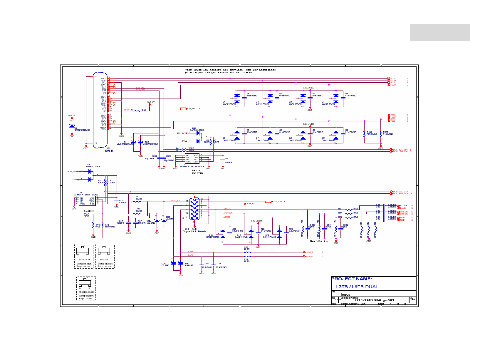
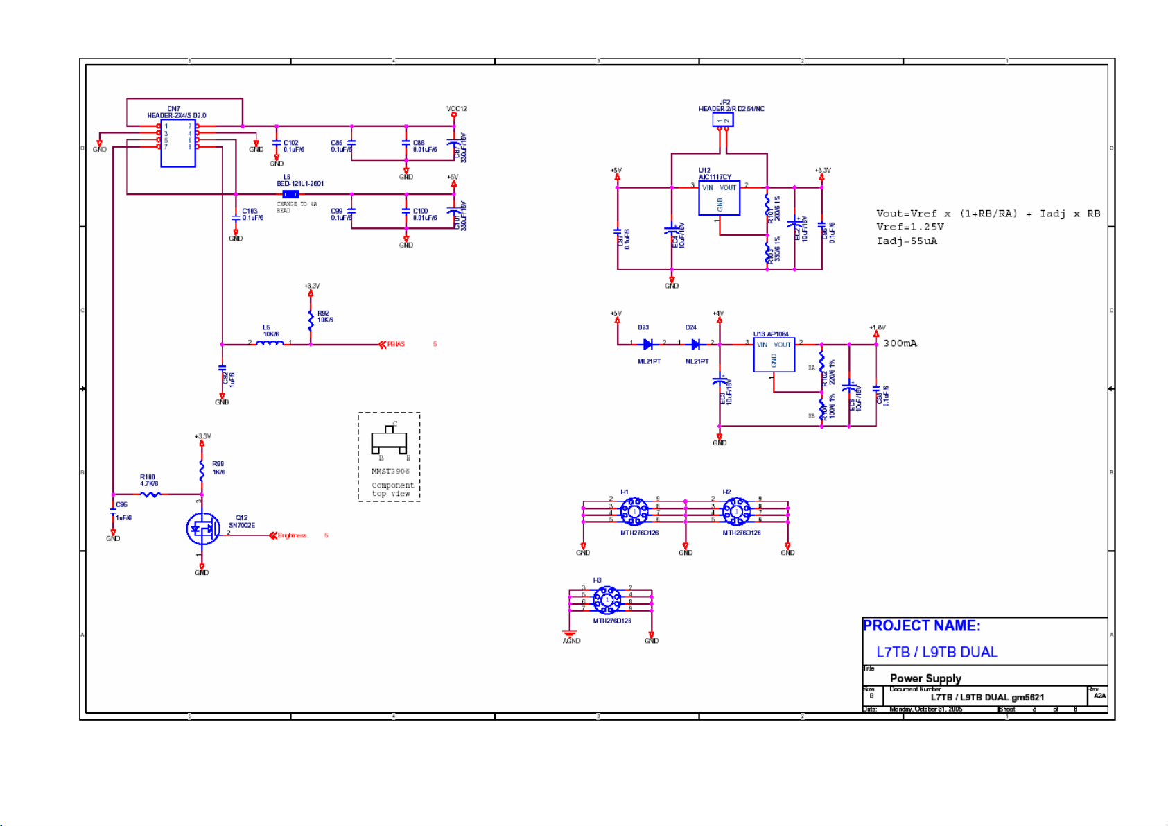
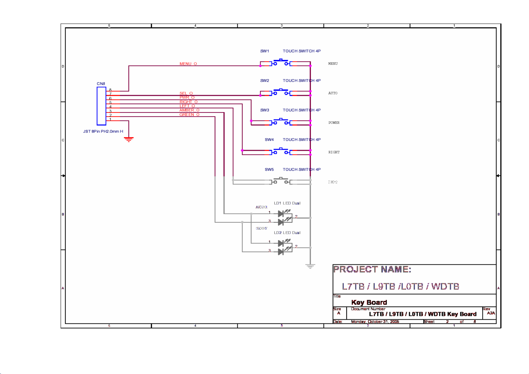
SCHEMATIC DIAGRAM Main Board Circuit
Chapter 7
- 42-
Page 42
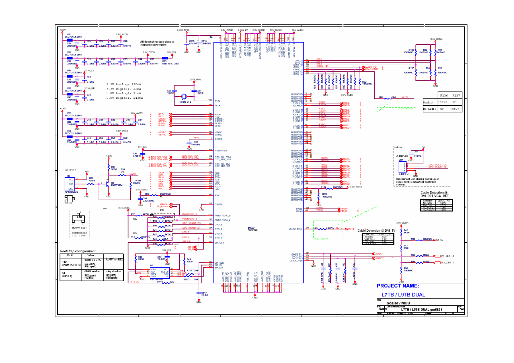
- 43 -
Page 43
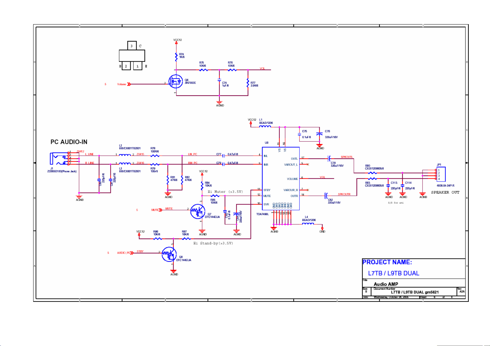
- 44 -
Page 44
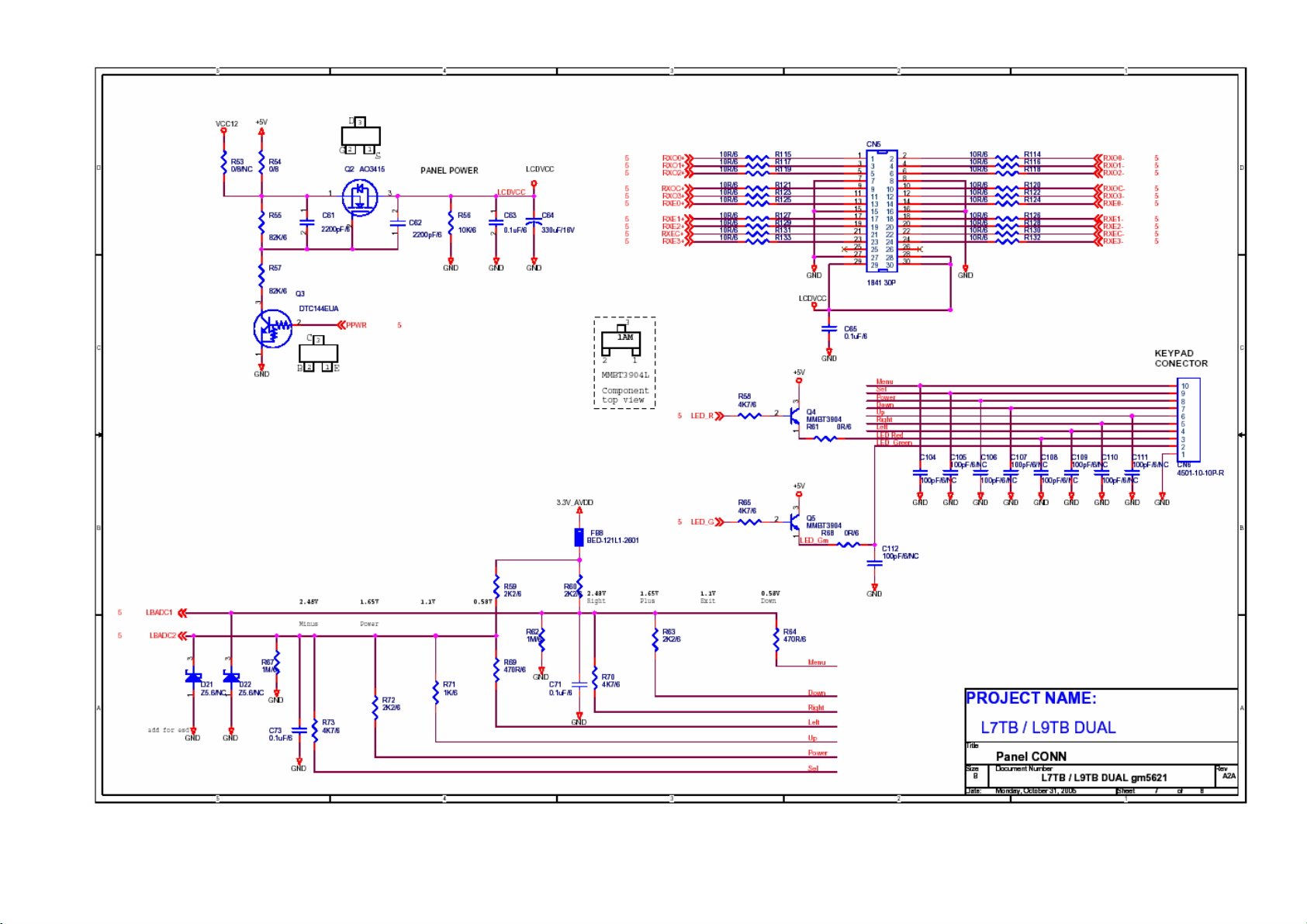
- 45 -
Page 45
- 46 -
Page 46
- 47 -
Page 47
Chapter 8
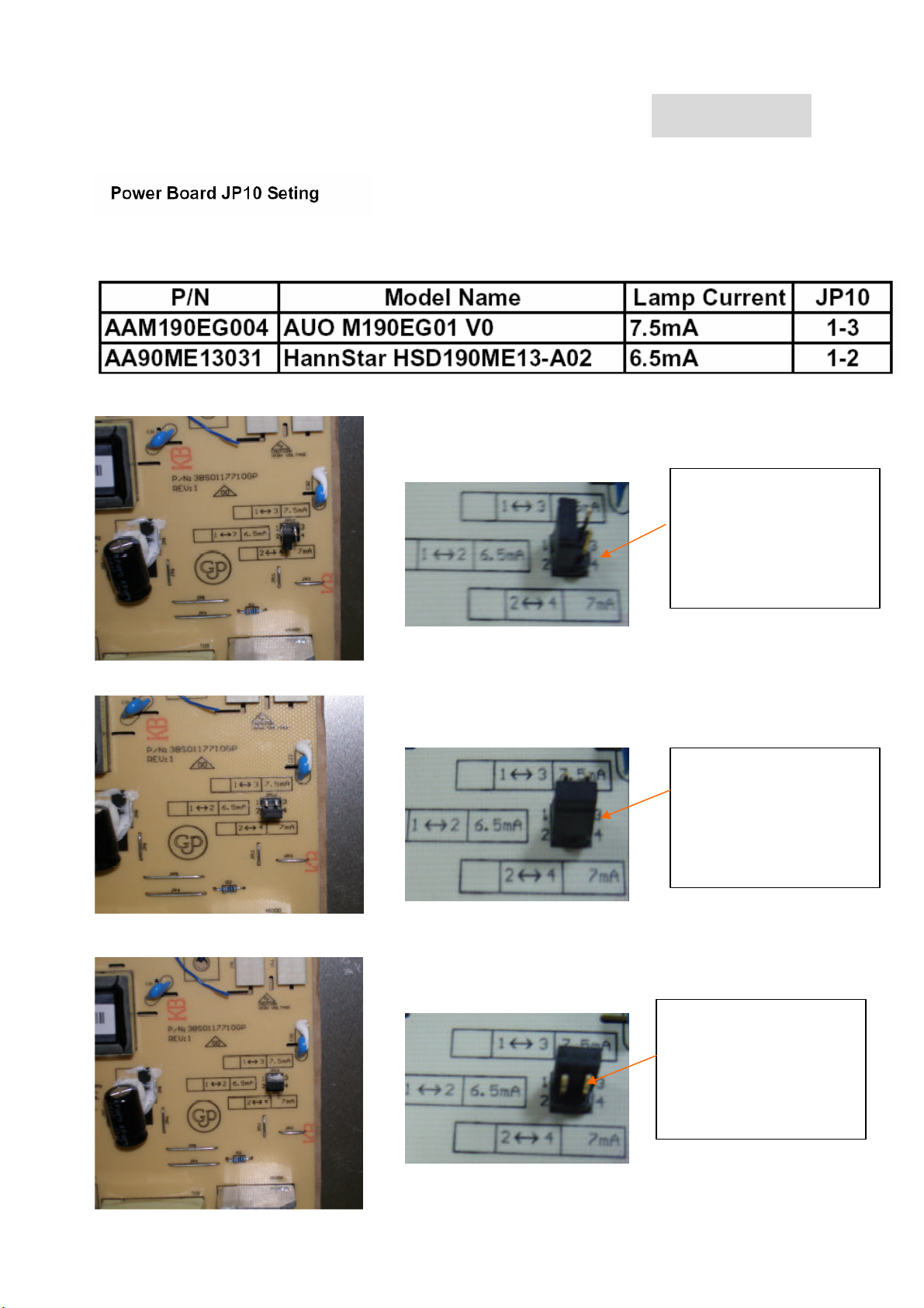
Power Board Current set Information
When the lamp current
value is 6.5mA, the
jumper should be done
as the picture left shows
When the lamp current
value is 7.0mA, the
jumper should be done
as the picture left shows
When the lamp current
value is 7.5mA, the
jumper should be done
as the picture left shows
- 48 -
 Loading...