

Page 1

T able of Contents
TCO99 Notice.......................................................................................................................
FCC Statement Warning..........................................................................................................
Canadian DOC Notice............................................................................................................
Precautions..................................................................................................................... 1
Package contents............................................................................................................. 2
Installation instructions ................................................................................................. 2
Assembling the Monitor .................................................................................................... 2
Detaching the Monitor ........................................................................................................ 2
Adjusting the Viewing Angle .............................................................................................. 3
Connecting the Devices ...................................................................................................... 3
Switching the Power .............................................................................................................. 3
Adjusting display settings ......................................................................................................
External Controls ......................................................................................................... 4
OSD options ........................................................................................................................................................
OSD Menu .............................................................................................................................................
Brightness & Contrast ............................................................................................................................
Tracking ...................................................................................................................................
Position ....................................................................................................................................
Color ........................................................................................................................................
Language setting......................................................................................................................
OSD option.......................................................................................................…....................
Auto configuration....................................................................................................................
Innformation.............................................................................................................................
Recall.......................................................................................................................................
General Specifications........................................................................................................................................
Technical Information..........................................................................................................................................
Pin assignment.......................................................................................................................................
Standard timing table..............................................................................................................................
Troubleshooting......................................................................................................................................
10
1
2
3
3
3
4
4
4
4
4
5
5
5
5
6
6
6
6
6
7
7
7
7
7
8
8
8
9
Page 2

Page1-2 stands for TCO'99 model only.
Please see back label for model distinction.
Congratulations!
You have just purchased a TCO'99 approved and labelled product!
Your choice has provided you with a product developed for professional use. Your purchase has also contributed to reducing the
burden on the environment and also to the further development of
environmentally adapted electronics products.
Why do we have environmentally labelled computers?
In many countries, environmental labelling has become an established method for encouraging the adaptation of goods and
services to the environment. The main problem, as far as computers and other electronics equipment are concerned, is that
environmentally harmful substances are used both in the products and during their manufacture.
Since it is not so far possible to satisfactorily recycle the majority of electronics equipment, most of these potentially damaging
substances sooner or later enter nature.
There are also other characteristics of a computer, such as energy consumption levels, that are important from the viewpoints of
both the work (internal) and natural (external) environments. Since all methods of electricity generation have a negative effect on
the environment (e.g. acidic and climate-influencing emissions, radioactive waste), it is vital to save energy. Electronics equipment
in offices is often left running continuously and thereby consumes a lot of energy.
What does labelling involve?
This product meets the requirements for the TCO'99 scheme, which provides for international and environmental labelling of
personal computers. The labelling scheme was developed as a joint effort by the TCO (The Swedish Confederation of Professional
Employees), Svenska Naturskyddsforeningen (The Swedish Society for Nature Conservation) and Statens Energimyndighet (The
Swedish National Energy Administration). Approval requirements cover a wide range of issues: environment, ergonomics,
usability, emission of electric and magnetic fields, energy consumption and electrical and fire safety. The environmental demands
impose restrictions on the presence and use of heavy metals, brominated and chlorinated flame retardants,
CFCs (freons) and chlorinated solvents, among other things. The product must be prepared for recycling and the manufacturer is
obliged to have an environmental policy which must be adhered to in each country where the company implements its operational
policy. The energy requirements include a demand that the computer and/or display, after a certain period of inactivity, shall reduce
its power consumption to a lower level in one or more stages. The length of time to reactivate the computer shall be reasonable for
the user. Labelled products must meet strict environmental demands, for example, in respect of the reduction of electric and
magnetic fields, physical and visual ergonomics and good usability. On the Back page of this folder, you will find a brief summary
of the environmental requirements met by this product. The complete
environmental criteria document may be ordered from:
TCO Development
SE-114 94 Stockholm, Sweden
Fax: +46 8 782 92 07
Email (Internet): [email protected]
Current information regarding TCO'99 approved and labeled products may also be obtained via the Internet, using the address:
http://www.tco-info.com/
1
Page 3

Environmental requirements
Flame retardants
Flame retardants are present in printed circuit boards, cables, wires, casings and housings. Their purpose is to prevent, or at least
to delay the spread of fire. Up to 30% of the plastic in a computer casing can consist of flame retardant substances. Most flame
retardants contain bromine or chloride, and those flame retardants are chemically related to another group of environmental toxins,
PCBs. Both the flame retardants containing bromine or chloride and the PCBs are suspected of giving rise to severe health effects,
including reproductive damage in fish-eating birds and mammals, due to the bio-accumulative* processes. Flame retardants have
been found in human blood and researchers fear that disturbances in foetus development may occur. The elevant TCO'99
demand requires that plastic components weighing more than 25 grams must not contain flame retardants with organically bound
bromine or chlorine. Flame retardants are allowed in the printed circuit boards since no substitutes are available.
Cadmium
Cadmium is present in rechargeable batteries and in the colour-generating layers of certain computer displays. Cadmium
damages the nervous system and is toxic in high doses. The relevant TCO'99 requirement states that batteries, the colorgenerating layers of display screens and the electrical or electronics components must not contain any cadmium.
Mercury
Mercury is sometimes found in batteries, relays and switches. It damages the nervous system and is toxic in high doses. The
relevant TCO'99 requirement states that batteries may not contain any mercury. It also demands that mercury is not present in any
of the electrical or electronics components associated with the labelled unit.
CFCs (freons)
The relevant TCO'99 requirement states that neither CFCs nor HCFCs may be used during the manufacture and assembly of the
product. CFCs (freons) are sometimes used for washing printed circuit boards. CFCs break down ozone and thereby damage the
ozone layer in the stratosphere, causing increased reception on earth of ultraviolet light with e.g. increased risks of skin cancer
(malignant melanoma) as a consequence.
Lead**
Lead can be found in picture tubes, display screens, solders and capacitors. Lead damages the nervous system and in higher
doses, causes lead poisoning. The relevant TCO'99 requirement permits the inclusion of lead since no replacement has yet been
developed.
* Bio-accumulative is defined as substances which accumulate within living organisms
** Lead, Cadmium and Mercury are heavy metals which are Bio-accumulative.
FCC Statement Warning
This equipment has been tested and found to comply with the limits for a Class B digital device, pursuant to Part 15 of the FCC
Rules. These limits are designed to provide reasonable protection against harmful interference in a residential installation. This
equipment generates, uses, and can radiate radio frequency energy, and if not installed and used in accordance with the
instruction, may cause harmful interference to radio communications. However, there is no guarantee that interference will not
occur in a particular installation. If this equipment does cause harmful interference to radio or television reception, which can be
determined by turning the equipment off and on, the user is encouraged to try to correct the interference by one or more of the
following measures:
. Reorient or relocate the receiving antenna.
. Increase the separation between the equipment and the receiver.
. Connect the equipment into an outlet on a circuit different from that to which the receiver is connected.
. Consult the dealer or an experienced radio/TV technician for help.
Any changes or modifications not expressly approved by the manufacturers may void the user's authority to operate this
equipment.
NOTE
A shielded-type signal cord is required in order to meet the FCC emission limits and also to prevent interference to the radio and
television reception. It is essential that only the supplied signal cord be used.
2
Page 4

Canadian DOC Notice
This Class B digital apparatus meets all requirements of the Canadian Interference-Causing Equipment Regulations.
Cet appareil numerique de la classe B repecte toutes les exigences du Reglement sur le materiel brouilleur du Canada.
Preface
This manual is designed to assist users in setting up and using the LCD Monitor. Information in his document has been carefully
checked for accuracy; however, no guarantee is given to the correctness of the contents. The information in this document is
subject to change without notice. This document contains proprietary information protected by copyright. All rights are reserved.
No part of this manual may be reproduced by any mechanical, electronic or other means, in any form, without prior written
permission of the manufacturer.
Important Safety Instructions
Please read the following instructions carefully. This manual should be retained for future use.
1. To clean LCD Monitor screen;
-- Power off LCD Monitor and unplug the AC Cord.
-- Spray a non-solvent cleaning solution onto a rag and clean the screen gently.
2. Do not place the LCD Monitor near a window. Exposing the monitor to rain water, moisture or sunlight can
severely damage it.
3. Do not apply pressure to the LCD screen. Excess pressure may cause permanent damage to the display.
4. Do not remove the cover or attempt to service this unit by yourself.
Servicing of any nature should be performed by an authorized technician.
5. Store LCD Monitor in a room with a room temperature of -20°C ~ 60°C (or -4°F ~ 140°F).
Storing the LCD Monitor outside this range could result in permanent damage.
6. If any of the following occurs, immediately unplug your monitor and call an authorized technician.
* Monitor to PC signal cable is frayed or damaged.
* Liquid spilled into LCD Monitor or the monitor has been exposed to rain.
* LCD Monitor or the case is damaged.
Package contents
LCD Monitor Power Cord Audio cable (optional)
3
Page 5
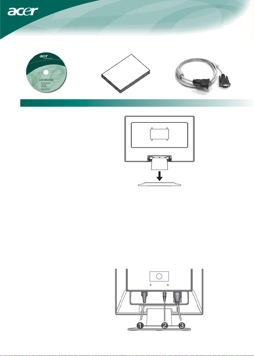
User manual (CD) Quick setup guide VGA cable
Installation instruction
Assembling the monitor
1. Position the monitor on top of the stand.
2.Connect the stand into the neck of monitor along the track.
Detaching the monitor
Important
First, find a clean, flat surface to place the monitor after removing it from the stand. Place a clean dry cloth under the monitor to
protect it further. Pull the monitor slightly up and away from the stand.
Adjusting the Viewing Angle
The viewing angle of the monitor ranges from forward 5° to backward 20°.
Caution: Do not force the LCD Monitor over its maximum viewing angle settings as stated above. Attempting this will result in
damaging the Monitor and Monitor stand.
Connecting the Devices
Please shut down the power of computer and monitor
before you do the connection.
4
Page 6
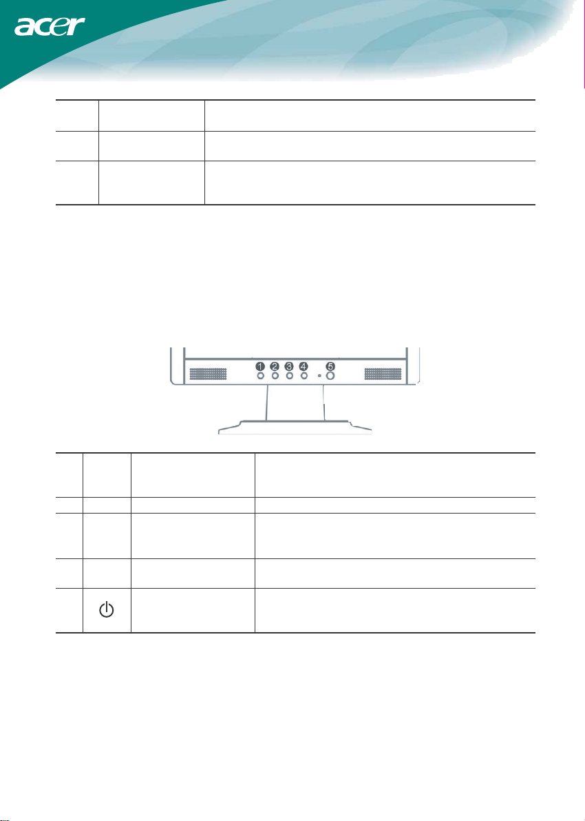
(1)
(2)
P
owe
r Code
A
udi
o cable
(
optiona
l
)
Attach the monitor to the power cord which should then be
inserted into a properly grounded electric socket.
Connect the audio input socket of the LCD monitor and the
computer by mens of the audio cable.
Connect the signal cable to the VGA output socket of the graphics
3)
(
VGA
C
able
card on the computer. Then tighten the thumbscrews on the
connector.
WAR
NING:
shape of the socket it is inserted into, and that none of the pins are bent or otherwise damaged.
S
witching the Power
First, switch the power on to the monitor, then switch the power on to the computer. When you see the LED on the power button
go green, this indicates the computer is ready for use. Allow about 10 seconds for the video signal to appear. If you do not see
the green light on the power button or a video signal, check the connections.
A
djusting display s
The D-Sub 15 pin plug of the VGA cable is trapezoid in shape. Make sure the shape of the plug matches the
etting
s
If OSD is active, press to exit. If OSD is inactive, press and the monitor
1
A
u
to
A
u
to configuration
will automatically optimize the display position, clock and phase of your
display.
2
<M
inus
If OSD is active, press to select or adjust OSD options.
If OSD is active, press to select or adjust OSD options. If OSD is
3
>P
lus
inactive, press once, then press the buttons marked <or > to adjust
the volume. (this function is optional only for models with speakers)
4
M
e
nu
OSD
manua
l
Press to view OSD.
Press again to exit.
Power on/off
5
powe
r
Green: power on
Orange: in sleep mode
OSD
option
s
Please refer to "External Controls" on Page 5.
To adjust the OSD settings:
1. Press the MENU button to open the OSD menu.
2. Use the buttons marked < or >, to highlight a control, then press the MENU
button to enter
3. Use the buttons marked < or >, to adjust the control to the desired level.
4. When you have finished making all selections, press the MENU button to exit
the OSD. (Or the adjustment will auto-save after 45 seconds.)
5
Page 7
OSD Menu
Brightness & Contrast
Tracking
Position
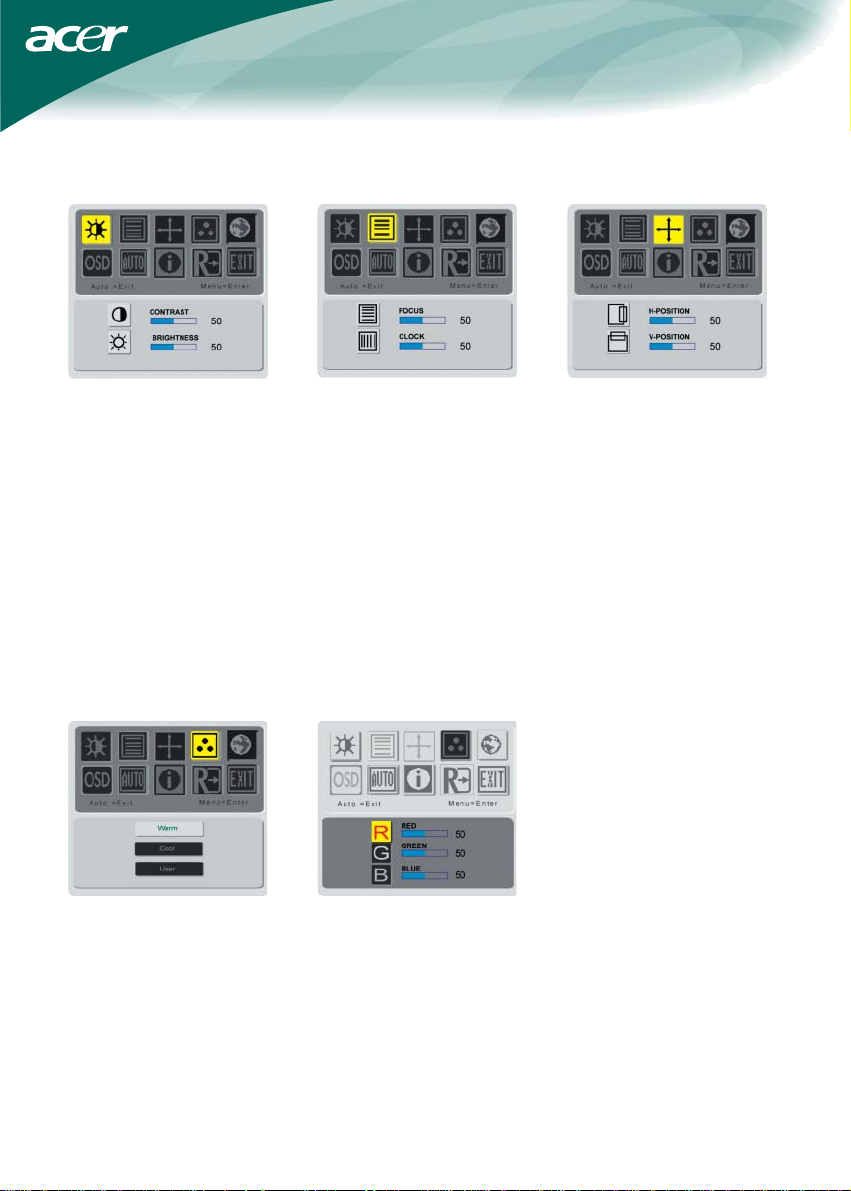
BRIGHTNESS:
This adjusts the brightness of the
picture on the screen. Adjustable
range from the value of 0 to 100.
CONTRAST:
This adjusts dark and light shades of
color relative to each other to achieve
a comfortable contrast. Adjustable
range from the value of 0 to 100.
Color temperature
There are three ways of adjusting
color temperature:
WARM:
Set the color temperature as CIE
coordinate 6500°K.
COOL:
Set the color temperature as CIE
coordinate 9300°K.
FOCUS:
This removes any horizontal
distortion and makes the picture
clear and sharp.
CLOCK:
If there are any vertical stripes seen
on the background of the screen this
renders themless noticeable by
minimizing their size. It also changes
the size of the horizontal screen.
User defined:
You can adjust the colors red, green
and blue to the intensity you desire.
V-Position:
This adjusts the vertical.
H-Position:
This adjusts the horizontal.
6
Page 8
Language
OSD position
Auto configuration
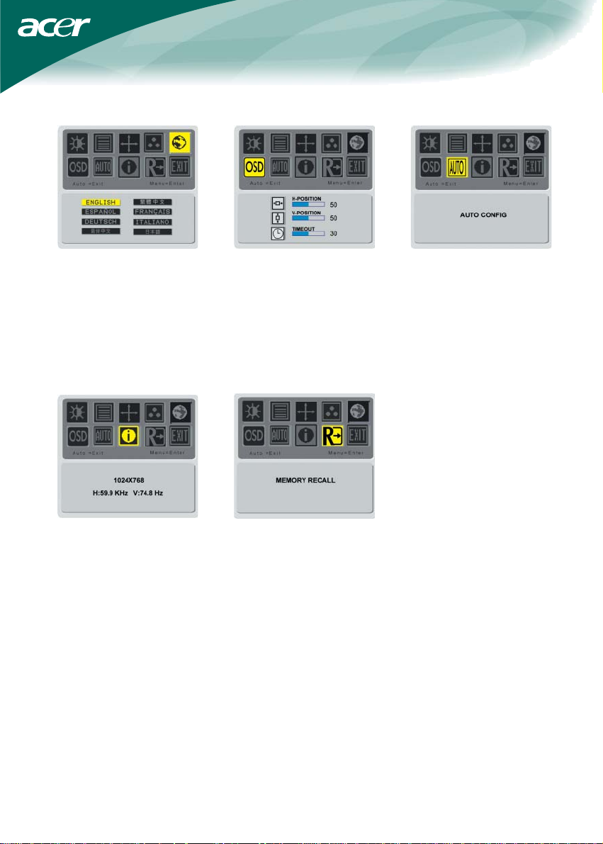
Select the OSD menu language from
English, German, French, Traditional
Chinese, Simplify Chinese,
Japanese, Italian and Spanish.
Information
This shows brief information on the
screen.
This changes the position of the OSD
window on the screen.
TIMEOUT function allow user define
the OSD appearing period from 10
seconds to 60 seconds.
Recall
Recall to factory default settings
Adjust the monitor parameter
automatically.
7
Page 9
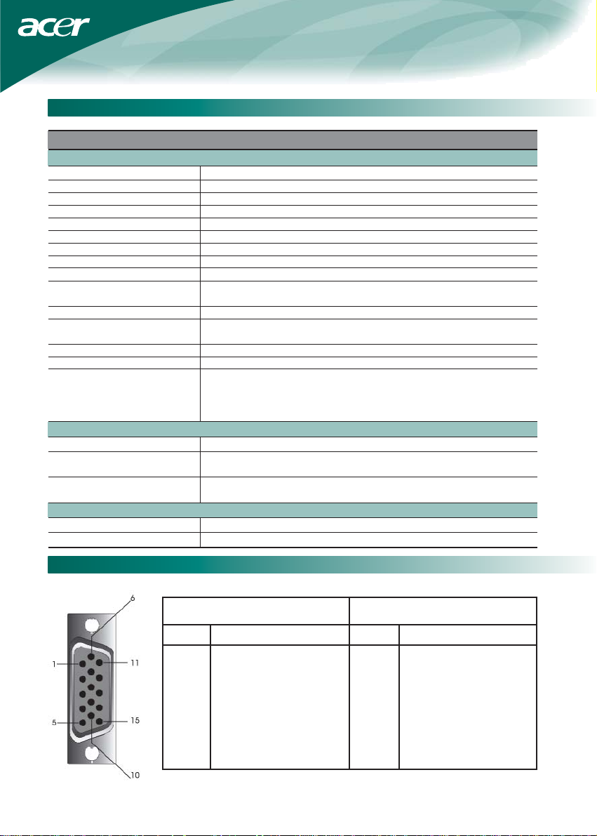
General Specification
Item Specification
Panel
Display 15-inch Flat panel active-matrix TFT LCD
Max resolution 1024 x 768 (XGA)
Pixel Pitch 0.297 mm X 0.297 mm
Color 262K (6 Bits)
Brightness 260 cd/m2 ( Typical)
Contrast Ratio 350:1 (Typical)
Response Time 5ms +20ms /25ms (Tr+Tf / typical)
View Angle of Horizontal 120 °
View Angle of Vertical 100 °
External Controls
Power Button ON/ OFF
Control Buttons Auto, MENU, <, >
Video Interface
Video Analog 0.7V
Sync TTL (+/ -)
Plug & Play DDC2B
EMI and Safety UL(USA); CBC(B-Mark)(Poland); PSB(Singapore); TUV(Germany); CB;
Power
Power Source 100~240V AC, 50/60 Hz
Power consumption during < 24W
normal operation
Power consumption during < 3W
active off operation
Dimension and weight
Dimension (W_H_D) 343.4x351.5x159.8mm (base included)
Weight (Net/ Gross) 2.75Kg/ 3.8Kg
BSMI (Taiwan); CCC (China); PSE (Japan); FCC(USA); C-tick (Australia);
CE(Europe); VCCI (Japan); TCO'99; ISO13406-2; TUV/GS; TUV/Ergo;
WHQL(Microsoft)
T echnical Information
Pin assignment
Signal Signal
PIN Description PIN Description
1 Red 9 +5V
2 Green 10 N.C.
3 Blue 11 N.C.
4 N.C. 12 DDC_SDA
5 GND 13 HSYNC
6 Red_GND 14 VSYNC.
7 Green_GND 15 DDC_SCL
8 Blue_GND
8
Page 10
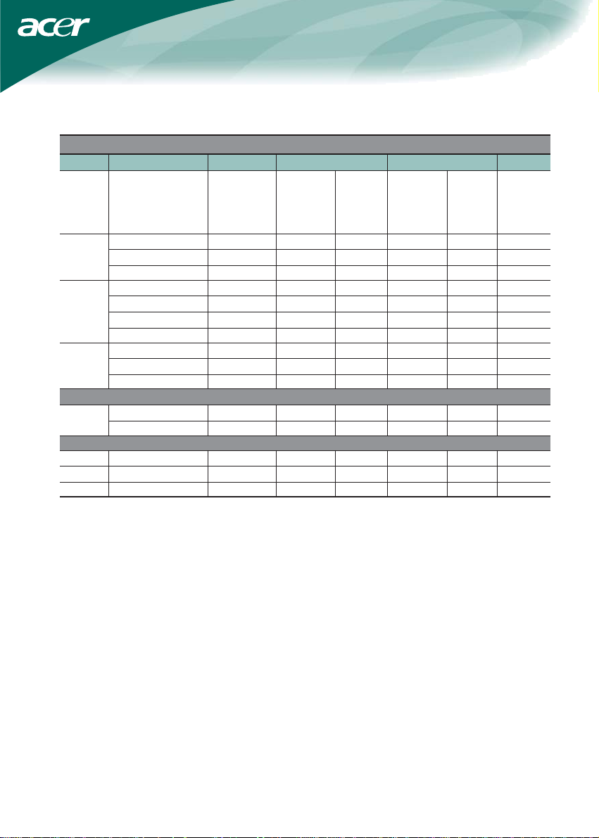
Standard timing table
If the selected timing is NOT included in table below, this LCD monitor will go into the sleep mode.
VESA MODES
Horizontal Vertical
Mode Resolution Total Nominal Sync Nominal Sync Nominal
Frequency Polarity Frequency Polarity Pixel
+/-0.5KHz +/-1Hz Clock
(MHz)
VGA 640*480@60Hz 800*525 31.469 N 59.940 N 25.175
640*480@72Hz 832*520 37.861 N 72.809 N 31.500
640*480@75Hz 840*500 37.500 N 75.000 N 31.500
SVGA 800*600@56Hz 1024*625 35.156 P 56.250 P 36.000
800*600@60Hz 1056*628 37.879 P 60.317 P 40.000
800*600@72Hz 1040*666 48.077 P 72.188 P 50.000
800*600@75Hz 1056*625 46.875 P 75.000 P 49.500
XGA 1024*768@60Hz 1344*806 48.363 N 60.004 N 65.000
1024*768@70Hz 1328*806 56.476 N 70.069 N 75.000
1024*768@75Hz 1312*800 60.023 P 75.029 P 78.750
IBM MODES
EGA 640*350@70Hz 800*449 31.469 P 70.086 N 25.175
720x400@70Hz 900*449 31.469 N 70.087 P 28.322
MAC MODES
SVGA 832*624@75Hz 1152*667 49.728 N 74.551 N 57.284
XGA 1024*768@60Hz 1312*813 48.780 N 60.001 N 64.000
XGA 1024*768@75Hz 1328*804 60.241 N 74.927 N 80.000
9
Page 11

T roubleshooting
This LCD Monitor has pre-adjusted using factory standard VGA timings. Due to the output timing differences among various VGA
cards in the market, users may initially experience an unstable or unclear display whenever a new display mode or new VGA card
is selected.
Attention
This LCD Monitor Supports Multiple VGA Modes. Refer to the Standard Timing Table for a listing of modes supported by this LCD
Monitor.
PROBLEM Picture is unclear and unstable
The picture is unclear and unstable, please perform the following steps :
1. Enter PC to "Shut Down Windows" status while you're in MS-Windows environment.
2. Check the screen to see if there's any black vertical stripes appear. If there are,
take advantage of the "Clock" function in OSD menu and adjust (by increment or decrement numbers)
until those bars disappear.
3. Move to "FOCUS" function in OSD menu again and adjust the monitor screen to its most clear display.
4. Click "No" on "Shut Down Windows" and back to the normal PC operating environment.
PROBLEM There is no picture on LCD Monitor
If there's no picture on the LCD Monitor, please perform the following steps:
1. Make sure the power indicator on the LCD Monitor is ON, all connections are secured,
and the system is running on the correct timing. Refer to Chapter 3 for information on timing.
2. Turn off the LCD Monitor and then turn it back on again. If there is still no picture,
press the Adjustment Control button several times.
3. If step 2 doesn't work, connect your PC system to another external CRT.
If your PC system Functions properly with a CRT Monitor but it does not function with the LCD Monitor,
the output timing of the VGA card may be out of the LCD's synchronous range.
Please change to an alternative mode listed in the Standard Timing Table or replace the VGA card,
and then repeat steps 1 and 2.
PROBLEM There is no picture on LCD Monitor
If you have chosen an output timing that is outside of the LCD Monitor's synchronous range (Horizontal: 24 ~ 80 KHz and Vertical:
56 ~ 75 Hz), the OSD will display a "Out of Range" message. Choose a mode that is supported by your LCD Monitor. Also, if the
signal cable is not connected to LCD monitor at all or properly, the monitor screen will display a message "No Input Signal".
Caution: Do not attempt to service the monitor yourself or open the computer
yourself. Please refer all servicing to qualified service personnel if
the problems cannot be solved in "Troubleshooting" section.
10
 Loading...