

Page 1

Page1-2 stands for
TCO’99 model only.
Please see back label
for model distinction.
Congratulations!
You have just purchased a TCO'99 approved and labelled product!
Your choice has provided you with a product developed for
professional use. Your purchase has also contributed to reducing the
burden on the environment and also to the further development of
environmentally adapted electronics products.
Why do we have environmentally labelled computers?
In many countries, environmental labelling has become an established
method for encouraging the adaptation of goods and services to the
environment. The main problem, as far as computers and other
electronics equipment are concerned, is that environmentally harmful
substances are used both in the products and during their manufacture.
Since it is not so far possible to satisfactorily recycle the majority of
electronics equipment, most of these potentially damaging substances
sooner or later enter nature.
There are also other characteristics of a computer, such as energy
consumption levels, that are important from the viewpoints of both the
work (internal) and natural (external) environments. Since all methods
of electricity generation have a negative effect on the environment
(e.g. acidic and climate-influencing emissions, radioactive waste), it is
vital to save energy. Electronics equipment in offices is often left
running continuously and thereby consumes a lot of energy.
What does labelling involve?
This product meets the requirements for the TCO'99 scheme, which
provides for international and environmental labelling of personal
Page 2

computers. The labelling scheme was developed as a joint effort by
the TCO (The Swedish Confederation of Professional Employees),
Svenska Naturskyddsforeningen (The Swedish Society for Nature
Conservation) and Statens Energimyndighet (The Swedish National
Energy Administration).
Approval requirements cover a wide range of issues: environment,
ergonomics, usability, emission of electric and magnetic fields, energy
consumption and electrical and fire safety.
The environmental demands impose restrictions on the presence and
use of heavy metals, brominated and chlorinated flame retardants,
CFCs (freons) and chlorinated solvents, among other things. The
product must be prepared for recycling and the manufacturer is
obliged to have an environmental policy which must be adhered to in
each country where the company implements its operational policy.
The energy requirements include a demand that the computer and/or
display, after a certain period of inactivity, shall reduce its power
consumption to a lower level in one or more stages. The length of time
to reactivate the computer shall be reasonable for the user.
Labelled products must meet strict environmental demands, for
example, in respect of the reduction of electric and magnetic fields,
physical and visual ergonomics and good usability.
On the Back page of this folder, you will find a brief summary of the
environmental requirements met by this product. The complete
environmental criteria document may be ordered from:
Page 3

TCO Development
SE-114 94 Stockholm, Sweden
Fax: +46 8 782 92 07
Email (Internet): [email protected]
Current information regarding TCO'99 approved and labelled
products may also be
obtained via the Internet, using the address:
http://www.tco-info.com/
Environmental requirements
Flame retardants
Flame retardants are present in printed circuit boards, cables, wires,
casings and housings. Their purpose is to prevent, or at least to delay
the spread of fire. Up to 30% of the plastic in a computer casing can
consist of flame retardant substances. Most flame retardants contain
bromine or chloride, and those flame retardants are chemically related
to another group of environmental toxins, PCBs. Both the flame
retardants containing bromine or chloride and the PCBs are suspected
of giving rise to severe health effects, including reproductive damage
in fish-eating birds and mammals, due to the bio-accumulative
processes. Flame retardants have been found in human blood and
researchers fear that disturbances in foetus development may occur.
The relevant TCO'99 demand requires that plastic components
weighing more than 25 grams must not contain flame retardants with
organically bound bromine or chlorine. Flame retardants are allowed
in the printed circuit boards since no substitutes are available.
*
Cadmium
Cadmium is present in rechargeable batteries and in the
*
Bio-accumulative is defined as substances which accu mulate within living
organisms
Page 4

colour-generating layers of certain computer displays. Cadmium
damages the nervous system and is toxic in high doses. The relevant
TCO'99 requirement states that batteries, the color-generating layers
of display screens and the electrical or electronics components must
not contain any cadmium.
Mercury
Mercury is sometimes found in batteries, relays and switches. It
damages the nervous system and is toxic in high doses. The relevant
TCO'99 requirement states that batteries may not contain any mercury.
It also demands that mercury is not present in any of the electrical or
electronics components associated with the labelled unit.
CFCs (freons)
The relevant TCO'99 requirement states that neither CFCs nor HCFCs
may be used during the manufacture and assembly of the product.
CFCs (freons) are sometimes used for washing printed circuit boards.
CFCs break down ozone and thereby damage the ozone layer in the
stratosphere, causing increased reception on earth of ultraviolet light
with e.g. increased risks of skin cancer (malignant melanoma) as a
consequence.
Lead**
Lead can be found in picture tubes, display screens, solders and
capacitors. Lead damages the nervous system and in higher doses,
causes lead poisoning. The relevant TCO´99 requirement permits the
inclusion of lead since no replacement has yet been developed.
**
Lead, Cadmium and Mercury are heavy metals which are
Bio-accumulative.
Page 5

Operation Instructions
Thank you for purchasing this monitor, a high-resolution multi-scan
color monitor.
Please read this guide thoroughly before installation.
FCC RADIO FREQUENCY INTERFERENCE STATEMENT
WARNING: (FOR FCC CERTIFIED MODELS)
This monitor has been tested and found compliant with the limits for a
Class B digital device, pursuant to part 15 of the FCC Rules. These
limits are designed to provide proper protection against harmful
interference to a residential installation. This monitor generates, uses,
and can radiate radio frequency energy. Harmful interference to radio
communication may be led as a result if it‘s not properly installed and
used. However, there is no guarantee that interference will not occur
in a particular installation. If this monitor does cause serious
interference to radio or television reception, resetting the monitor may
determine it. Moreover, users are encouraged to correct interference
by doing one or more of the following:
! Reorient or relocate the receiving antenna.
! Move the monitor and the receiver further away from each other.
! Connect the monitor into an outlet on a circuit different from that
to which the receiver is connected.
! Consult your local dealer or an qualified technician
FCC Warning:
To assure a continued FCC compliance, a user must use a grounded
power supply cord and the provided shielded video interface cable
with bonded ferrite cores. Also, any unauthorized changes or
modifications to this monitor would void the user‘s authority to
operate this device.
Note: If necessary, shielded interface cables and AC power cord must
be used to meet the emission level limits.
EMI Certification
The Class B digital apparatus meets all requirements of the Canadian
Interference-Causing Equipment Regulation.
Cet appareil numerique de class B respecte toutes les exigences du
Reglement sur le materiel brouilleur du Canada.
.
Page 6

Content
Safety Precautions .......................................................................1
First Setup....................................................................................2
Front Panel Control .....................................................................3
Installation ...................................................................................3
Using OSD Functions..................................................................4
Technical Information ...............................................................10
Care and Maintenance ...............................................................11
Troubleshooting.........................................................................11
Page 7

Safety Precautions
This monitor is manufactured and tested on a ground principle
that a user’s safety comes first. However, improper use or
installation may result danger to the monitor as well as to the
user. Carefully go over the following WARNINGS before
installation and keep this guide handy.
WARNINGS:
# This monitor should be operated only at the correct power
sources indicated on the label on the rear end of the monitor.
If you’re unsure of the power supply in your residence,
consult your local dealer or power company.
# Do not try to repair the monitor yourself as it contains no
user-serviceable parts. The monitor should only be repaired
by a qualified technician.
# Do not remove the monitor cabinet. There is high-voltage
parts inside that may cause electric shock to human bodies,
even when the power cord is disconnected .
# Stop using the monitor if the cabinet is damaged. Have it
checked by a service technician.
# Put your monitor only in a clean, dry environment. Unplug
the monitor immediately if gets wet and consult your
service technician.
# Always unplug the monitor before cleaning it. Clean the
cabinet with a clean, dry cloth. Appl y non-ammonia based
cleaner onto the cloth, not directly onto the glass screen.
# Keep the monitor away from magnetic objects, motors, TV
sets, and transformer.
# Do not place heavy objects on the cable or power cord.
#
For PLUG CABLE EQUIPMENT, the Socket-outlet shall
be installed near the equipment and shall be easily
accessible.
1
Page 8
First Setup
Congratulation for purchasing this monitor of high performance!
This monitor comes with the following accessories :
$ Video cable with 15 pin D-SUB connector.
$ Power cable.
$ User guide book.
Quick Installation
1. Connect video cable
Make sure both the monitor
and computer are powered
OFF. Connect the video cable
to the computer, then to the
monitor.
2. Connect power cord
Connect the power cord to a
properly grounded AC outlet,
then to the monitor.
3. Power-ON computer and
monitor
Power-ON the computer, then
Power-ON the monitor.
4. Windows users
Timing Mode (Resolution and
Refresh Rate)
Example: 1024 x 768 @ 60 Hz
Resolution
Windows desktop > Properties >
Settings > “Desktop Area”. Set
the resolution.
Refresh Rate
See your graphic card’s user
guide for instructions.
: Setting the
Right-click on the
(vertical frequency)
2
Page 9
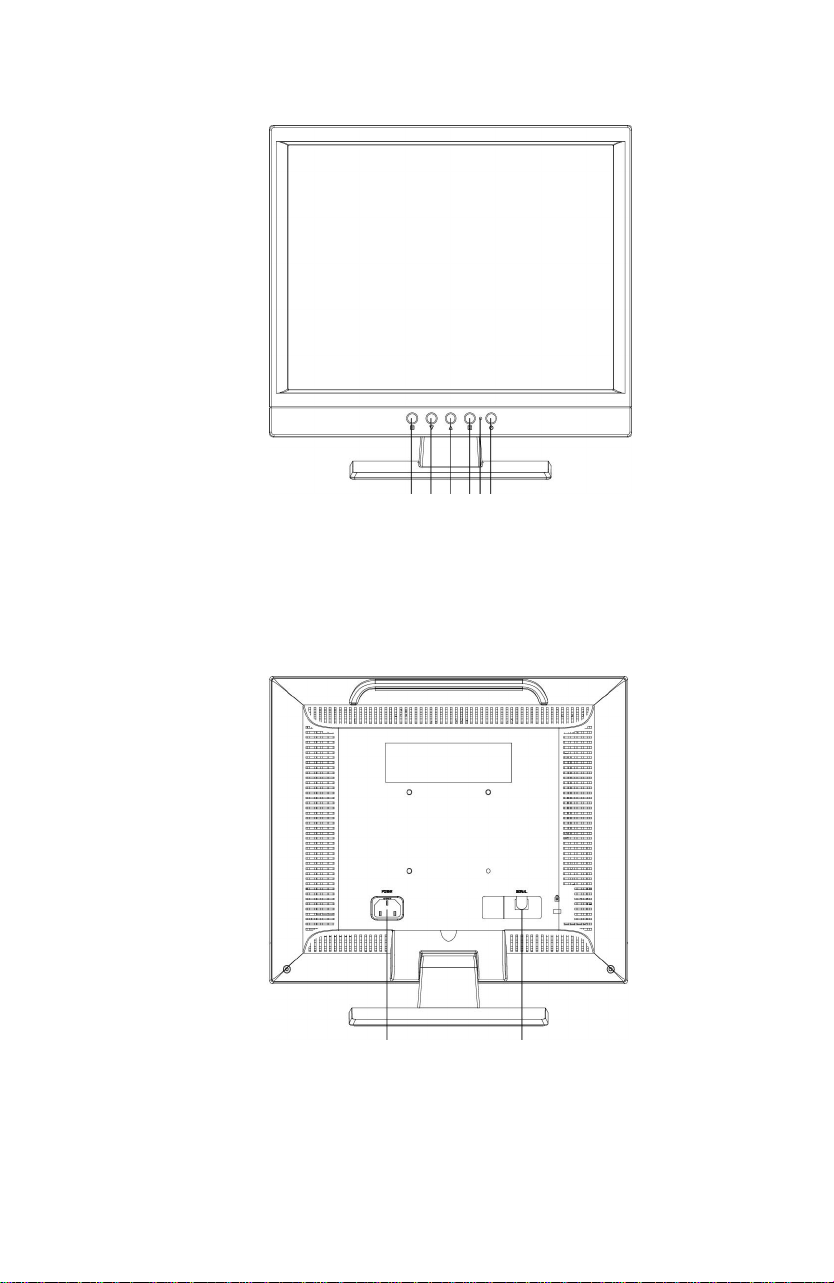
Front Panel Control
OSD ON/OFF
%
SCROLL DOWN
'
SCROLL UP
)
Installation
❼
POWER INPUT (AC INPUT)
❽
SIGNAL INPUT (VGA 15PIN D-SUB)
❶ ❷ ❸ ❹❺❻
ENTER
&
POWER ON/OFF
(
POWER INDICATOR
*
❼ ❽
3
Page 10
Using OSD Functions
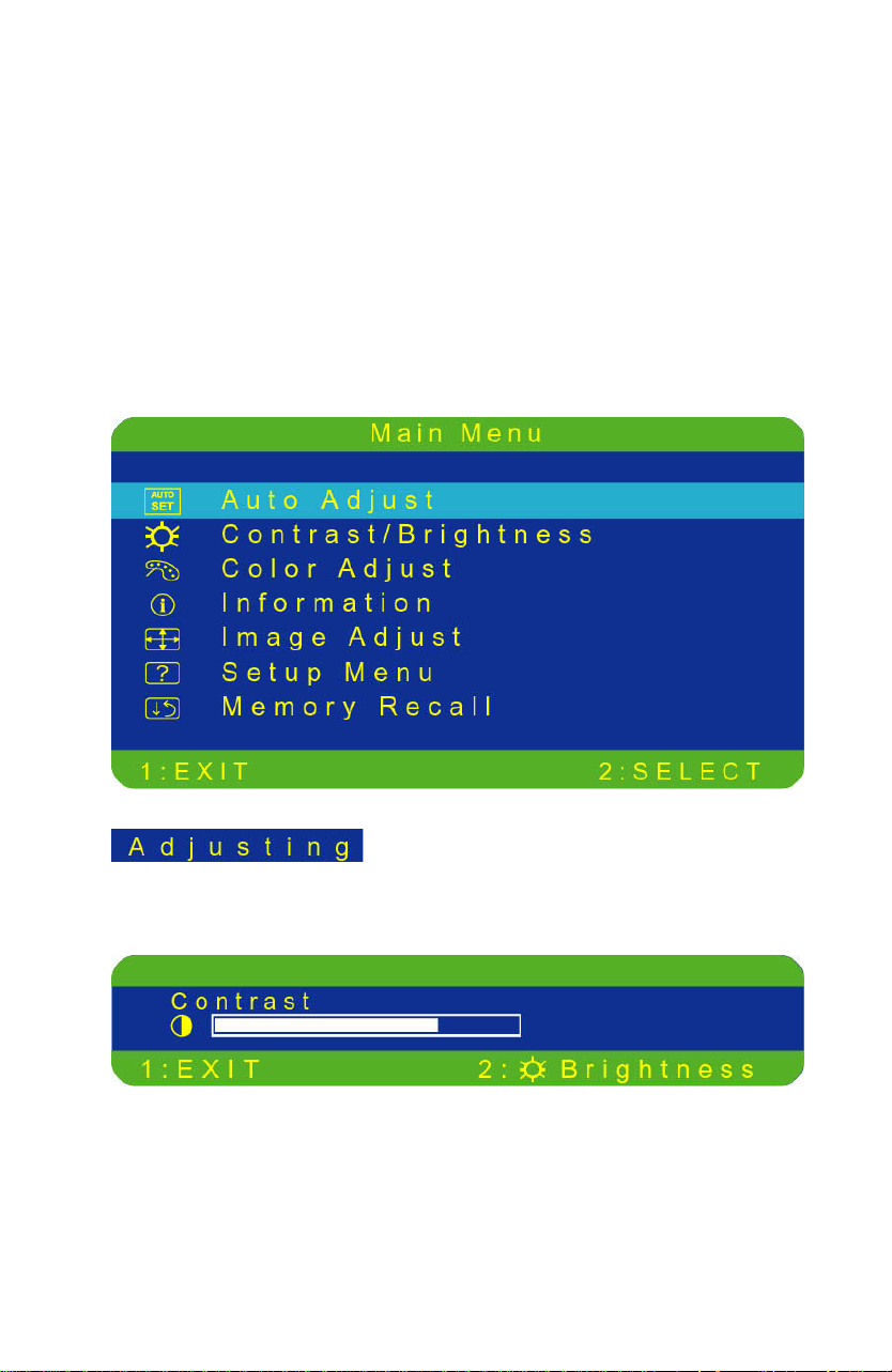
1. Press the ①①① button to display the main menu shown below.
2. Press the ▲ or ▼ button to scroll to the desired menu option.
3. Press the ②②② button to select the menu option.
4. Press the ▲ or ▼ button to select submenu option.
5. After making adjustment, press ①①① button to save changes and exit the
screen.
Main Menu
Auto Adjust: Auto adjust horizontal position, vertical position,
phase(Fine Tune) and Clock (H.Size).
Contrast: To adjust the foreground white level of screen image.
▲ : increase contrast, ▼ : decrease contrast.
4
Page 11
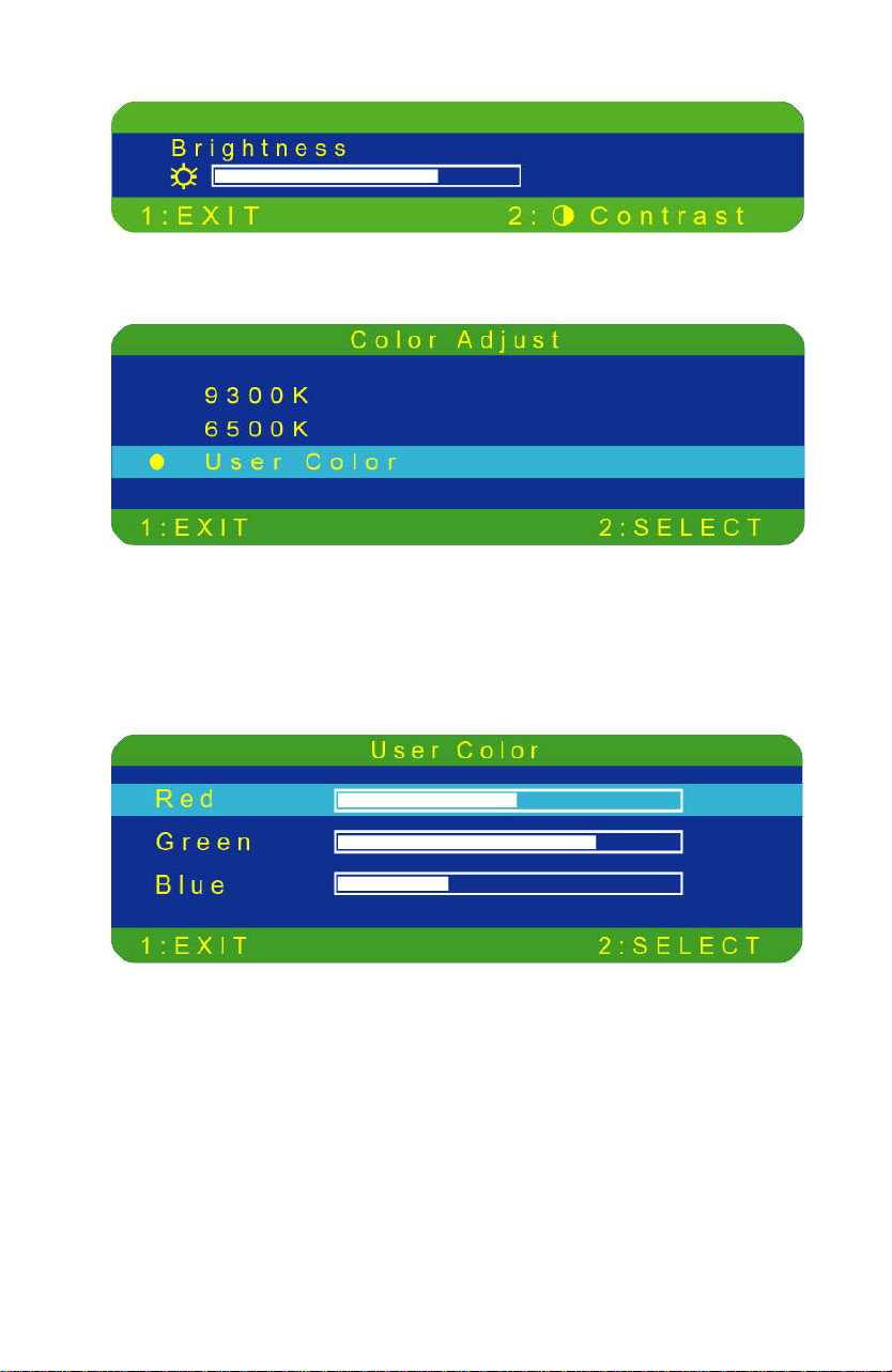
Brightness: To adjust the background black level of screenimage.
▲ : increase brightness, ▼ : decrease brightness.
Color Adjust: Provides three preset color adjustments:
9300K, 6500K and User Color for improved brightness and
color saturation. Above preset colors were only garanteed at default
contrast condition. Press button ②②②② to select the preset color.
9300K--Adds blue to screen image for cooler white.
6500K--Adds to screen image for warmer white and richer red.
User Color: Individual adjustments for red(R), green (G), blue (B).
1. Press button ②②②② to set adjustment and select next color to adjust.
2. Press ▼ or ▲ button to adjust selected color.
5
Page 12

Information: Displays information regarding the current input
signal coming from the graphic card in your computer.
Note: See your graphic card user guide for more information
about changing the resolution and refresh rate.
Image Adjust: Adjust Horizontal/ Vertical position, H.Size, Fine Tune
and Sharpness.
H./V. Position: To adjust the horizontal and vertical position of the video.
H. Position: ▲ : moves screen to right, ▼ : moves screen to left.
V. Position: ▲ : moves screen to up, ▼ : moves screen to down.
6
Page 13
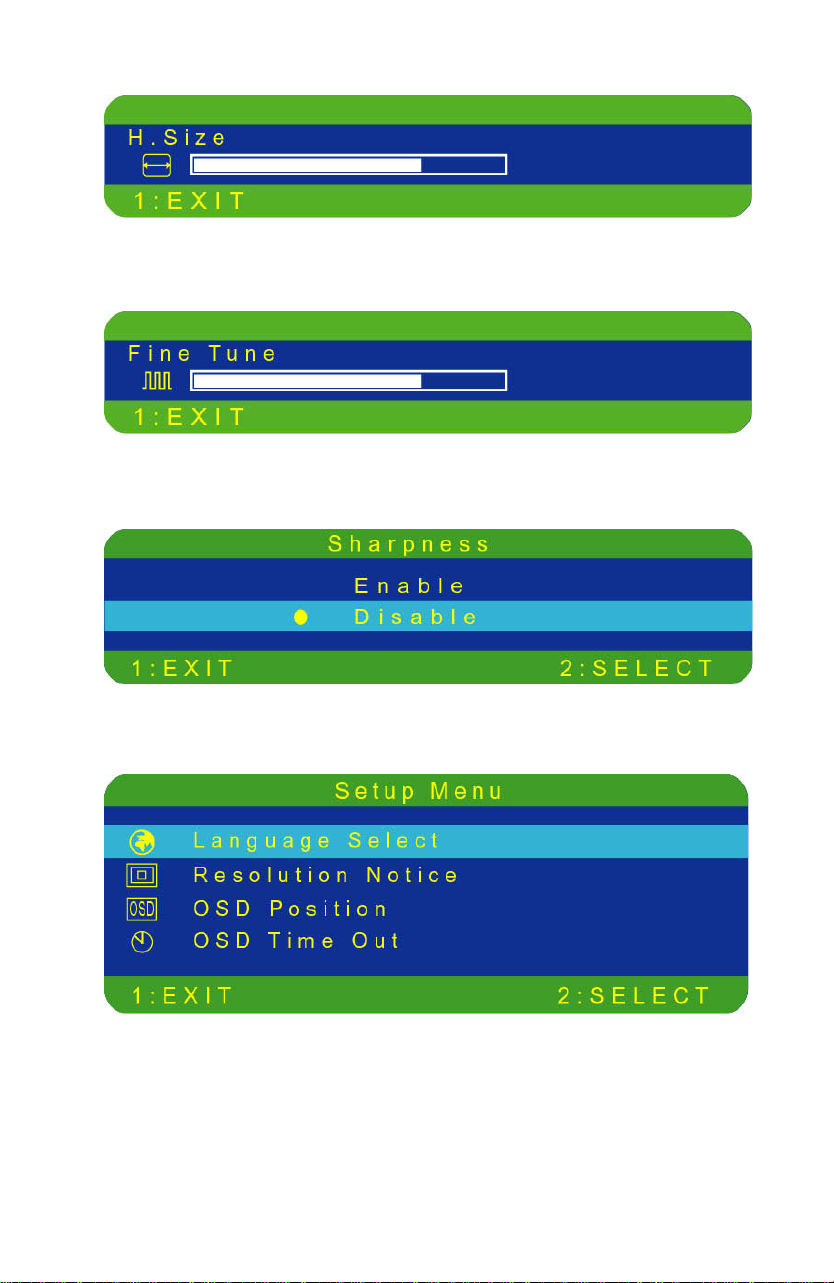
H.Size: Adjusts the width of screen image. ▼ decreases width of screen
image, ▲ increases width of screen image.
Fine Tune: To adjust the delay time. Press ▼ or ▲ to adjust to user
preference.
Sharpness: Adjusts the clarity of a non-XGA (1024x768) signal. Press
▼ or ▲ button to adjust.
Setup Menu: To setting Language Select, Resolution Notice, OSD
position and OSD Time Out.
7
Page 14
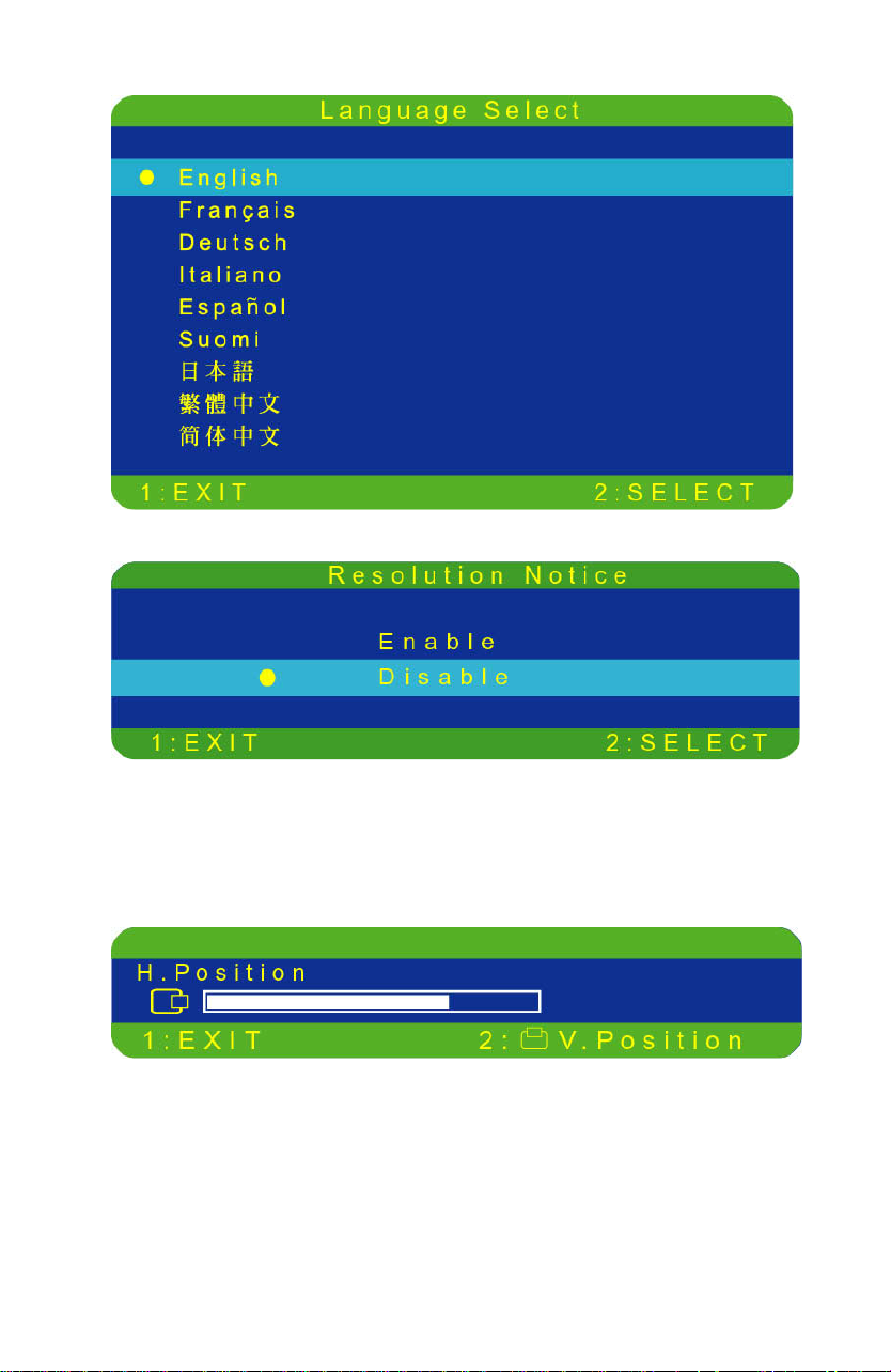
Language Select: Allows the user to choose from available languages.
Resolution Notice: There is a OSD message of "For best picture quality
change resolution to 1024 x 768" displayed on the screen after 30 seconds
Powering ON or changing mode to lower resolutions (640 x 480/ 720 x
400/ 800 x 600), if the function was "enable". Above message would not
display on screen if it was disable.
OSD Position: Press the ❷ button to select the horizontal or vertical
OSD position.
Horizontal OSD Position horizontally repositions all OSD
screens. ▲ moves OSD right, ▼ moves OSD left.
Vertical OSD Position vertically repositions all OSD screen.
▲ moves OSD up, ▼ moves OSD down.
8
Page 15
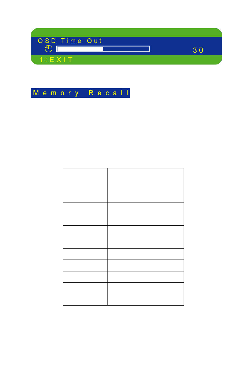
OSD Time Out: sets the length of time the Onscreen Display
screen is displayed before exiting.
Memory Recall: Return the adjustments back to factory settings.
Press the button ②②②② to select the Memory Recall menu option.
Timin g mod es
VESA 720 x 400 @ 70Hz
VESA 640 x 480 @ 60Hz
MAC 640 x 480 @ 67Hz
VESA 640 x 480 @ 75Hz
VESA 800 x 600 @ 56Hz
VESA 800 x 600 @ 60Hz
VESA 800 x 600 @ 72Hz
VESA 800 x 600 @ 75Hz
MAC 832 x 624 @ 75Hz
VESA 1024 x 768 @ 60Hz
VESA 1024 x 768 @ 70Hz
VESA 1024 x 768 @ 75Hz
9
Page 16
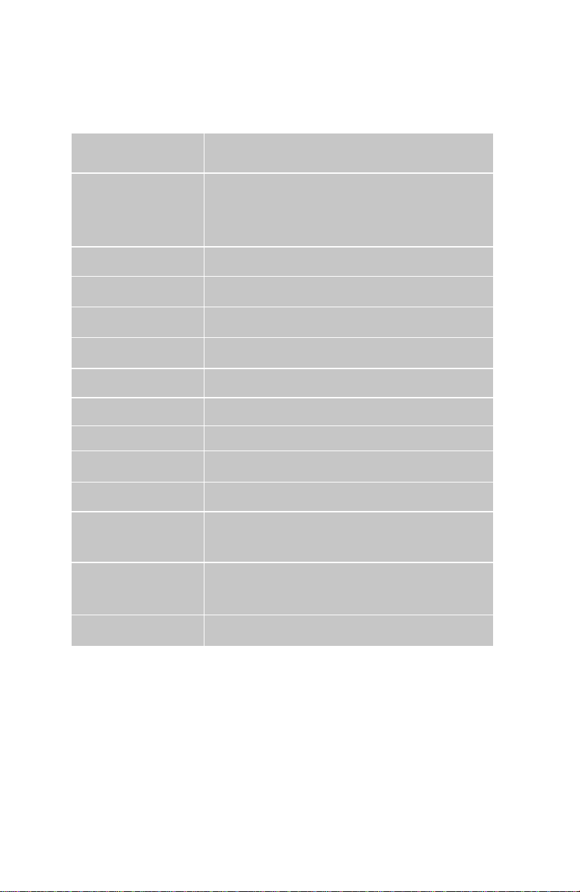
Technical Information
Technical Specification
LCD Panel
15.0” TFT
Power Management
Displayable Resolution
Pixel Dimension
LCD Display Color
Viewing Angle
Tilt
Contrast Ratio
Brightness
Response Time
Active Display Area
Temperature
Compliance
Energy Star compliant VESA
DPMS compatible
< 2 W
XGA 1024 x 768 max. Vertical Frequecy 75Hz max.
0.297 x 0.297 mm
262K (6 bits/color)
150/125, CR > 5
+20°, -3°
400 : 1 (typical)
250 cd /m2 (typical)
25 ms.
304.1 mm x 228.1 mm
Operating: 0°C ~ +40°C
Storage: -20°C ~ + 60°C
UL, TÜV/GS, FCC-B, Energy Star, PSB, PSE, C-Tick,
TCO’99
Power
Input Voltage AC100-240 V
10
Page 17

Care and Maintenance
Care
! Avoid exposing your monitor directly to sunlight or other heat source.
Place your monitor away from the sun to reduce glare.
! Put your monitor in a well ventilated area. Do not place anything heavy
on top of your monitor.
! Make certain your monitor is installed in a clean and moisture-free area.
! Keep your monitor away from magnets, motors, transformers, speakers,
and TV sets.
Note:
1.
Move the LCD out of the package and take off the plastic bag and
Polystyrene Foam.
2.
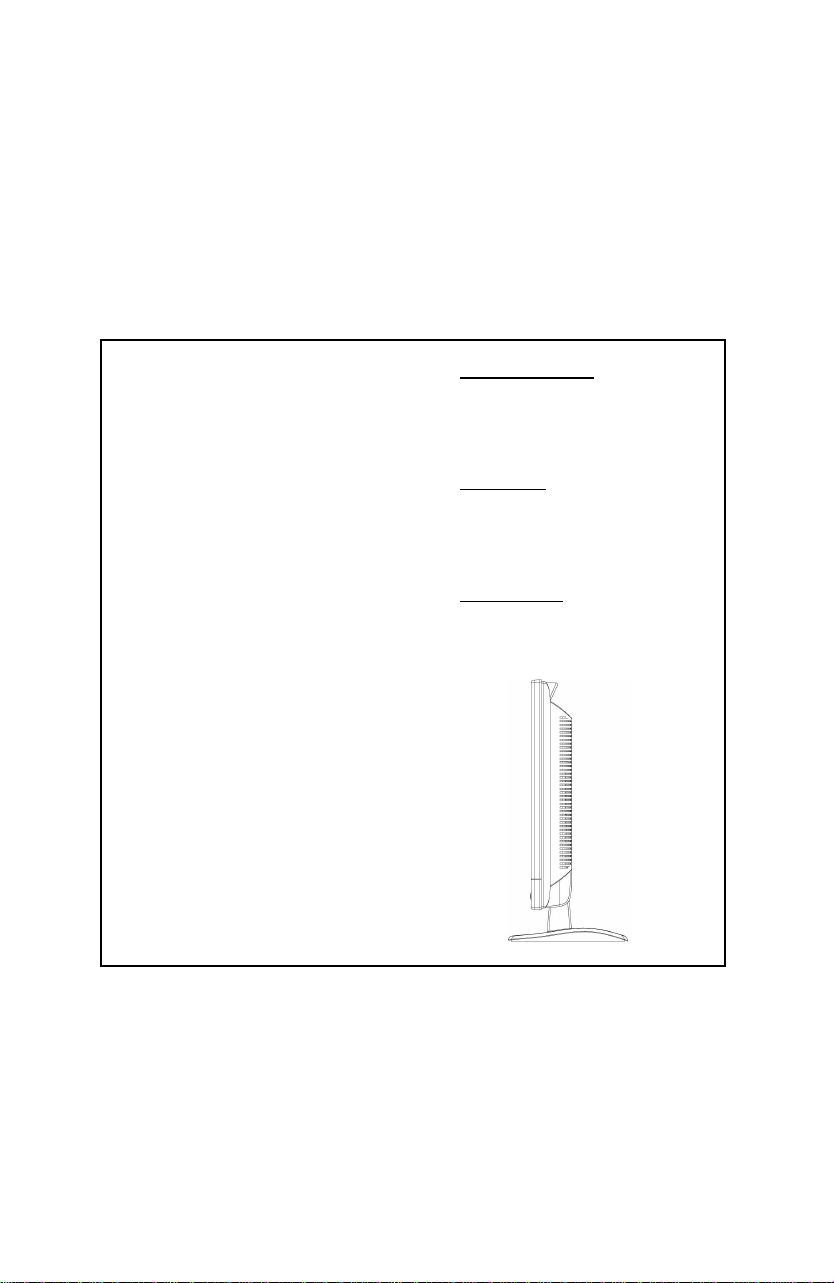
Pull the base from Parellel versus Panel to Vertical.
3.
Adjust the Panel within 5 degree leaning forward and 20 degree leaning
backward. You must bend harder to exceed 20 degree backward but this
range is for packing the unit to a small size for storage only. Caution:
Panel exceeding +5 to -20 degree could cause the unit unstable and the
harm will be unpredictable.
Safety Tips:
! If smoke, abnormal noise or odor came out of your monitor, switch off
the power immediately and call your service center.
! Never remove the rear cover of your monitor cabinet. The display unit
inside contains high-voltage parts and may cause electric shock to human
bodies.
!
Never try to repair your monitor yourself. Always call your service center
or a qualified technician to fix it.
Troubleshooting
No power
!
Make sure A/C power is securely connected to the power adapter and the
power supply is firmly connected to the monitor.
!
Plug another electrical device into the power inlet to verify that the outlet
is supplying proper voltage.
! Make sure all short cables are installed.
Power on but no screen image
!
Make sure the video cable supplied with the monitor is tightly secured to
the video output port on back of the computer. If not, tightly secure it.
! Adjust brightness.
11
Page 18

Wrong or abnormal colors
!
If any colors (red, green, blue) are missing, check the video cable to
make sure it is securely connected. Loose or broken pins in the cable
connector could cause an improper connection.
! Connect the monitor to another computer.
12
 Loading...