


A3-A11
S E R V I C E G U I D E

Table of Contents
Chapter 1. Hardware Specifications and Configurations
Features . . . . . . . . . . . . . . . . . . . . . . . . . . . . . . . . . . . . . . . . . . . . . . . . . . . . . . . . . . . . 1-2
Tablet tour. . . . . . . . . . . . . . . . . . . . . . . . . . . . . . . . . . . . . . . . . . . . . . . . . . . . . . . . . . . 1-5
Front View . . . . . . . . . . . . . . . . . . . . . . . . . . . . . . . . . . . . . . . . . . . . . . . . . . . . 1-5
Rear View . . . . . . . . . . . . . . . . . . . . . . . . . . . . . . . . . . . . . . . . . . . . . . . . . . . . 1-6
Top View . . . . . . . . . . . . . . . . . . . . . . . . . . . . . . . . . . . . . . . . . . . . . . . . . . . . . 1-7
Right View . . . . . . . . . . . . . . . . . . . . . . . . . . . . . . . . . . . . . . . . . . . . . . . . . . . . 1-8
Left View . . . . . . . . . . . . . . . . . . . . . . . . . . . . . . . . . . . . . . . . . . . . . . . . . . . . . 1-9
System Block Diagram . . . . . . . . . . . . . . . . . . . . . . . . . . . . . . . . . . . . . . . . . . . . . . . . . 1-10
Specifications Table . . . . . . . . . . . . . . . . . . . . . . . . . . . . . . . . . . . . . . . . . . . . . . . . . . . 1-11
Chapter 2. Diagnostic Utilities
Introduction . . . . . . . . . . . . . . . . . . . . . . . . . . . . . . . . . . . . . . . . . . . . . . . . . . . . . . . . . . 2-2
Diagnostic Tool SOP. . . . . . . . . . . . . . . . . . . . . . . . . . . . . . . . . . . . . . . . . . . . . . . . . . . 2-2
Main Menu . . . . . . . . . . . . . . . . . . . . . . . . . . . . . . . . . . . . . . . . . . . . . . . . . . . . 2-3
Testing User Interface (UI). . . . . . . . . . . . . . . . . . . . . . . . . . . . . . . . . . . . . . . . 2-3
Test Report UI . . . . . . . . . . . . . . . . . . . . . . . . . . . . . . . . . . . . . . . . . . . . . . . . . 2-4
CSD DL Tool. . . . . . . . . . . . . . . . . . . . . . . . . . . . . . . . . . . . . . . . . . . . . . . . . . . . . . . . . 2-9
Preparation . . . . . . . . . . . . . . . . . . . . . . . . . . . . . . . . . . . . . . . . . . . . . . . . . . . 2-9
Using the CSD DL Tool . . . . . . . . . . . . . . . . . . . . . . . . . . . . . . . . . . . . . . . . . . 2-11
NVRAM Writer Tool . . . . . . . . . . . . . . . . . . . . . . . . . . . . . . . . . . . . . . . . . . . . . . . . . . . 2-13
Preparation . . . . . . . . . . . . . . . . . . . . . . . . . . . . . . . . . . . . . . . . . . . . . . . . . . . 2-13
Using the NVRAM Writer Tool . . . . . . . . . . . . . . . . . . . . . . . . . . . . . . . . . . . . . 2-16
G-Sensor Calibration Tool . . . . . . . . . . . . . . . . . . . . . . . . . . . . . . . . . . . . . . . . . . . . . . 2-19
Preparation . . . . . . . . . . . . . . . . . . . . . . . . . . . . . . . . . . . . . . . . . . . . . . . . . . . 2-19
Using the G-Sensor Calibration Tool . . . . . . . . . . . . . . . . . . . . . . . . . . . . . . . . 2-22
Chapter 3. Jumper and Connector Locations
Mainboard Top View . . . . . . . . . . . . . . . . . . . . . . . . . . . . . . . . . . . . . . . . . . . . . . . . . . . 3-2
Mainboard Bottom View . . . . . . . . . . . . . . . . . . . . . . . . . . . . . . . . . . . . . . . . . . . . . . . . 3-3
Control Board View . . . . . . . . . . . . . . . . . . . . . . . . . . . . . . . . . . . . . . . . . . . . . . . . . . . . 3-4
Switch Board View . . . . . . . . . . . . . . . . . . . . . . . . . . . . . . . . . . . . . . . . . . . . . . . . . . . . 3-5
Chapter 4. Troubleshooting
General Information . . . . . . . . . . . . . . . . . . . . . . . . . . . . . . . . . . . . . . . . . . . . . . . . . . . 4-2
Power On Issues . . . . . . . . . . . . . . . . . . . . . . . . . . . . . . . . . . . . . . . . . . . . . . . 4-3
No Display Issues . . . . . . . . . . . . . . . . . . . . . . . . . . . . . . . . . . . . . . . . . . . . . . 4-4
LCD Picture Failure . . . . . . . . . . . . . . . . . . . . . . . . . . . . . . . . . . . . . . . . . . . . . 4-5
Touch Screen Failure. . . . . . . . . . . . . . . . . . . . . . . . . . . . . . . . . . . . . . . . . . . . 4-6
Internal Speaker Failure. . . . . . . . . . . . . . . . . . . . . . . . . . . . . . . . . . . . . . . . . . 4-7
Extended Earphone Failure . . . . . . . . . . . . . . . . . . . . . . . . . . . . . . . . . . . . . . . 4-8
USB Test Failure . . . . . . . . . . . . . . . . . . . . . . . . . . . . . . . . . . . . . . . . . . . . . . . 4-9
Camera Failure . . . . . . . . . . . . . . . . . . . . . . . . . . . . . . . . . . . . . . . . . . . . . . . . 4-10
WiFi & BT Function Test Failure . . . . . . . . . . . . . . . . . . . . . . . . . . . . . . . . . . . 4-11
GPS Function Test Failure. . . . . . . . . . . . . . . . . . . . . . . . . . . . . . . . . . . . . . . . 4-12
3G Function Test Failure . . . . . . . . . . . . . . . . . . . . . . . . . . . . . . . . . . . . . . . . . 4-13
Other Functions Failure . . . . . . . . . . . . . . . . . . . . . . . . . . . . . . . . . . . . . . . . . . 4-14
Chapter 5. Service and Maintenance
Introduction . . . . . . . . . . . . . . . . . . . . . . . . . . . . . . . . . . . . . . . . . . . . . . . . . . . . . . . . . . 5-3
Recommended Equipment . . . . . . . . . . . . . . . . . . . . . . . . . . . . . . . . . . . . . . . . . . . . . . 5-3
i

Maintenance Flowchart. . . . . . . . . . . . . . . . . . . . . . . . . . . . . . . . . . . . . . . . . . . . . . . . . 5-4
Getting Started . . . . . . . . . . . . . . . . . . . . . . . . . . . . . . . . . . . . . . . . . . . . . . . . . . . . . . . 5-5
Micro SD Card Removal . . . . . . . . . . . . . . . . . . . . . . . . . . . . . . . . . . . . . . . . . 5-6
Micro SD Card Installation . . . . . . . . . . . . . . . . . . . . . . . . . . . . . . . . . . . . . . . . 5-7
SIM Card Removal. . . . . . . . . . . . . . . . . . . . . . . . . . . . . . . . . . . . . . . . . . . . . . 5-8
SIM Card Installation . . . . . . . . . . . . . . . . . . . . . . . . . . . . . . . . . . . . . . . . . . . . 5-9
Lower Case Removal. . . . . . . . . . . . . . . . . . . . . . . . . . . . . . . . . . . . . . . . . . . . 5-10
Lower Case Installation . . . . . . . . . . . . . . . . . . . . . . . . . . . . . . . . . . . . . . . . . . 5-14
Speaker Removal . . . . . . . . . . . . . . . . . . . . . . . . . . . . . . . . . . . . . . . . . . . . . . 5-17
Speaker Installation . . . . . . . . . . . . . . . . . . . . . . . . . . . . . . . . . . . . . . . . . . . . . 5-20
Touch Control Board Removal. . . . . . . . . . . . . . . . . . . . . . . . . . . . . . . . . . . . . 5-23
Touch Control Board Installation . . . . . . . . . . . . . . . . . . . . . . . . . . . . . . . . . . . 5-24
Touch Control Board FFC Removal. . . . . . . . . . . . . . . . . . . . . . . . . . . . . . . . . 5-25
Touch Control Board FFC Installation . . . . . . . . . . . . . . . . . . . . . . . . . . . . . . . 5-26
Battery Removal . . . . . . . . . . . . . . . . . . . . . . . . . . . . . . . . . . . . . . . . . . . . . . . 5-27
Battery Installation . . . . . . . . . . . . . . . . . . . . . . . . . . . . . . . . . . . . . . . . . . . . . . 5-30
Vibrator Module Removal . . . . . . . . . . . . . . . . . . . . . . . . . . . . . . . . . . . . . . . . 5-33
Vibrator Module Installation . . . . . . . . . . . . . . . . . . . . . . . . . . . . . . . . . . . . . . . 5-34
Switch Board Removal. . . . . . . . . . . . . . . . . . . . . . . . . . . . . . . . . . . . . . . . . . . 5-35
Switch Board Installation . . . . . . . . . . . . . . . . . . . . . . . . . . . . . . . . . . . . . . . . . 5-37
Rear Camera Removal . . . . . . . . . . . . . . . . . . . . . . . . . . . . . . . . . . . . . . . . . . 5-40
Rear Camera Installation . . . . . . . . . . . . . . . . . . . . . . . . . . . . . . . . . . . . . . . . . 5-42
LVDS Cable Removal . . . . . . . . . . . . . . . . . . . . . . . . . . . . . . . . . . . . . . . . . . . 5-44
LVDS Cable Installation . . . . . . . . . . . . . . . . . . . . . . . . . . . . . . . . . . . . . . . . . . 5-45
Mainboard Removal. . . . . . . . . . . . . . . . . . . . . . . . . . . . . . . . . . . . . . . . . . . . . 5-46
Mainboard Installation . . . . . . . . . . . . . . . . . . . . . . . . . . . . . . . . . . . . . . . . . . . 5-49
Front Camera Removal . . . . . . . . . . . . . . . . . . . . . . . . . . . . . . . . . . . . . . . . . . 5-52
Front Camera Installation. . . . . . . . . . . . . . . . . . . . . . . . . . . . . . . . . . . . . . . . . 5-53
WiFi Antenna Removal . . . . . . . . . . . . . . . . . . . . . . . . . . . . . . . . . . . . . . . . . . 5-54
WiFi Antenna Installation . . . . . . . . . . . . . . . . . . . . . . . . . . . . . . . . . . . . . . . . . 5-55
3G Antenna (Main) Removal . . . . . . . . . . . . . . . . . . . . . . . . . . . . . . . . . . . . . . 5-56
3G Antenna (Main) Installation . . . . . . . . . . . . . . . . . . . . . . . . . . . . . . . . . . . . 5-57
3G Antenna (Auxiliary) Removal . . . . . . . . . . . . . . . . . . . . . . . . . . . . . . . . . . . 5-58
3G Antenna (Auxiliary) Installation. . . . . . . . . . . . . . . . . . . . . . . . . . . . . . . . . . 5-59
Chapter 6. FRU (Field Replaceable Unit) List
Exploded Diagram . . . . . . . . . . . . . . . . . . . . . . . . . . . . . . . . . . . . . . . . . . . . . . . . . . . . 6-3
FRU List . . . . . . . . . . . . . . . . . . . . . . . . . . . . . . . . . . . . . . . . . . . . . . . . . . . . . . . . . . . . 6-5
Screw List . . . . . . . . . . . . . . . . . . . . . . . . . . . . . . . . . . . . . . . . . . . . . . . . . . . . . . . . . . . 6-8
Chapter 7. Test Compatible Components
Android OS Environment Test . . . . . . . . . . . . . . . . . . . . . . . . . . . . . . . . . . . . . . . . . . . 7-2
A3-A11 . . . . . . . . . . . . . . . . . . . . . . . . . . . . . . . . . . . . . . . . . . . . . . . . . . . . . . . 7-2
Chapter 8. Online Support Information
Introduction . . . . . . . . . . . . . . . . . . . . . . . . . . . . . . . . . . . . . . . . . . . . . . . . . . . . . . . . . . 8-2
ii

Revision History
Please refer to the table below for the updates made on this service guide.
Date Chapter Updates
10/31/2013 1-8 First release
Copyright
Copyright © 2013 by Acer Incorporated. All rights reserved. No part of this publication may be
reproduced, transmitted, transcribed, stored in a retrieval system, or translated into any language
or computer language, in any form or by any means, electronic, mechanical, magnetic, optical,
chemical, manual or otherwise, without the prior written permission of Acer Incorporated.
Disclaimer
The information in this guide is subject to change without notice.
Acer Incorporated makes no representations or warranties, either expressed or implied, with
respect to the contents hereof and specifically disclaims any warranties of merchantability or fitness
for any particular purpose. Any Acer Incorporated software described in this manual is sold or
licensed "as is". Should the programs prove defective following their purchase, the buyer (and not
Acer Incorporated, its distributor, or its dealer) assumes the entire cost of all necessary servicing,
repair, and any incidental or consequential damages resulting from any defect in the software.
Acer is a registered trademark of Acer Corporation.
Intel is a registered trademark of Intel Corporation.
Other brand and product names are trademarks and/or registered trademarks of their respective
holders.
iii

Conventions
The following conventions are used in this manual:
WARNING:
Indicates a potential for personal injury.
CAUTION:
Indicates a potential loss of data or damage to equipment.
IMPORTANT:
Indicates information that is important to know for the proper completion of a
procedure, choice of an option, or completing a task.
NOTE:
Gives bits and pieces of additional information related to the current topic.
The following typographical conventions are used in this document:
• Book titles, directory names, file names, path names, and program/process names are shown
in italics.
Example:
the DRS5 User's Guide
/usr/local/bin/fd
the /TPH15spool_M program
• Computer output (text that represents information displayed on a computer screen, such as
menus, prompts, responses to input, and error messages) are shown in constant width.
Example:
[01] The server has been stopped
• User input (text that represents information entered by a computer user, such as command
names, option letters, and words) are shown in constant width bold. Variables contained within
user input are shown in angle brackets (< >).
Example:
At the prompt, type run <file name> -m
• Keyboard keys are shown in bold italics.
Example:
After entering data, press Enter.
• Screen output (text that represents information displayed on the system, such as menus,
prompts, responses to input, and error messages) are shown in bold.
Example:
On the main menu, select OK.
iv

General Information
This Service Guide provides you with all technical information relating to the basic configuration for
Acer's global product offering. To better fit local market requirements and enhance product
competitiveness, your regional office may have decided to extend the functionality of a machine
(e.g. add-on card, modem, or extra memory capabilities). These localized features are not covered
in this generic service guide. In such cases, contact your regional offices or the responsible
personnel/channel to provide you with further technical details.
When ordering FRU parts:
Check the most up-to-date information available on your regional web or channel. If, for whatever
reason, a part number change is made, it may not be noted in this printed service guide.
For Acer-authorized service providers:
Your Acer office may have a different part number code than those given in the FRU list of this
printed service guide. The list provided by your regional Acer office must be used to order FRU
parts for repair and service of customer machines.
v

CHAPTER 1
Hardware Specifications and Configurations
Hardware Specifications and Configurations . . . . . . . . . . . . . . . . .1-2
Features . . . . . . . . . . . . . . . . . . . . . . . . . . . . . . . . . . . . . . . . . . . . . . . . . . . . . . . 1-2
Tablet tour . . . . . . . . . . . . . . . . . . . . . . . . . . . . . . . . . . . . . . . . . . . . . . . . . . . . . 1-5
Front View . . . . . . . . . . . . . . . . . . . . . . . . . . . . . . . . . . . . . . . . . . . . . . . . . . 1-5
Rear View . . . . . . . . . . . . . . . . . . . . . . . . . . . . . . . . . . . . . . . . . . . . . . . . . . 1-6
Top View . . . . . . . . . . . . . . . . . . . . . . . . . . . . . . . . . . . . . . . . . . . . . . . . . . . 1-7
Right View . . . . . . . . . . . . . . . . . . . . . . . . . . . . . . . . . . . . . . . . . . . . . . . . . . 1-8
Left View . . . . . . . . . . . . . . . . . . . . . . . . . . . . . . . . . . . . . . . . . . . . . . . . . . . 1-9
System Block Diagram . . . . . . . . . . . . . . . . . . . . . . . . . . . . . . . . . . . . . . . . . . 1-10
Specifications Table . . . . . . . . . . . . . . . . . . . . . . . . . . . . . . . . . . . . . . . . . . . . 1-11

Hardware Specifications and Configurations
Features
The following is a summary of the computer’s many features:
Form Factor
• 10.1” Tablet
Operating System
• Android Jelly Bean
Platform
• MTK MT8389WK
System Memory
• RAM: DDR3 1GB
• eMMC: 16GB / 32GB
Display
LCM
• 10.1" TFT-LCD (1280 x 800)
Low voltage
85-degree view angle
LVDS interface
Audio Subsystem
• Microphone
• Speaker
• 3.5mm Audio Jack
Camera
Front Camera
• 0.3MP Camera with Fix Focus (OV7675)
• Video capture recording at 30fps @ (640 x 480) VGA in MP4 format
1-2 Hardware Specifications and Configurations

Rear Camera
• 5MP Camera with Fix Focus (OV5648)
• Photo capture at 15fps @ 2592 x 1944 in JPEG
• Video capture recording at 30fps @ 1080p in MP4 format
Connectivity
3G
• MTK _ MT6167
Wi-Fi
• IEEE 802.11 b/g/n
Bluetooth
• Bluetooth
USB
• Micro USB 2.0 Type B port
• Support USB 2.0 OTG
Expansion Slot
®
v4.0
• MicroSD memory card up to 32G (SDHC 2.0 compatible)
Special Keys and Controls
• Capacitive Multi-Touch Screen
• Touch controller - Synaptics S7300B
• Function buttons
Side (mechanical key):
• Volume Up, Volume Down
•Power
Sensors
•G-Sensor
• Gyroscope
I/O Ports
• HDMI® Micro Connector with HDCP support
• MicroSD memory Card slot
• Micro-B Hyper USB OTG
• Micro SIM slot
Hardware Specifications and Configurations 1-3

Dimensions and Weight
Dimension
• 260 (L) x 175 (W) x 10.35 (T) mm
Weight
• 570g
Power Adapter and Battery
Battery
• Rechargeable Lithium-Ion Polymer battery
• Capacity 7300mAh
• Battery-life:
Video playback when CABC on: minimum 9 hours when play 720P H.264 video
playback on system (not streaming, Wifi/3G/BT off, backlight 125nit)
Stand-by on flight mode: minimum 700 hours
Youtube playback 720p video up to 5 hours via WIFI. (LCD backlight 125nit)
Charging time: 1 hour to 20% battery capacity (in dark mode)/ 6 hours from empty to
full battery by AC adapter (in dark mode)
Power Adapter
• Voltage range/frequency: 100 ~ 240V AC, 50/60 Hz
• DC output: 5.35V and 2A, 10.7W
Others
• Shut down pinhole
Green Requirement
• Rohs compliance
• WEEE compliance
• SMT Green process
1-4 Hardware Specifications and Configurations

Tablet tour
1
2
Front View
Figure 1-1. Front View
Table 1-1. Front View
# Item Description
1 Touch Screen 10.1-inch,
2 Camera 0.3-megapixel camera for video chatting and self-portrait images.
1280 x 800
capacitive touch screen.
Hardware Specifications and Configurations 1-5

Rear View
1
Figure 1-2. Rear View
Table 1-2. Rear View
# Item Description
1 Rear Camera 5-megapixel camera for video chatting and self-portrait images.
1-6 Hardware Specifications and Configurations
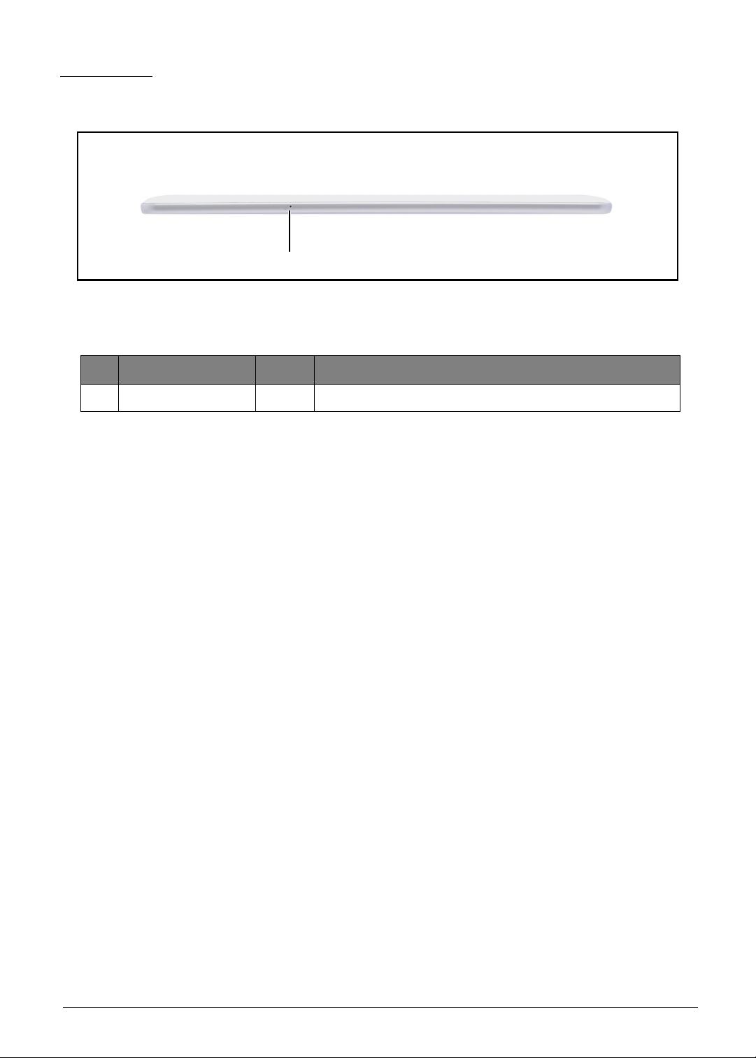
Top View
1
Figure 1-3. Top View
Table 1-3. Top View
# Item Description
1 Microphone Receives audio input.
Hardware Specifications and Configurations 1-7

Right View
1
2
Figure 1-4. Right View
Table 1-4. Right View
# Item Description
1 Volume Control Increases or decreases the tablet volume.
2 Right Speaker Emits stereo audio.
1-8 Hardware Specifications and Configurations
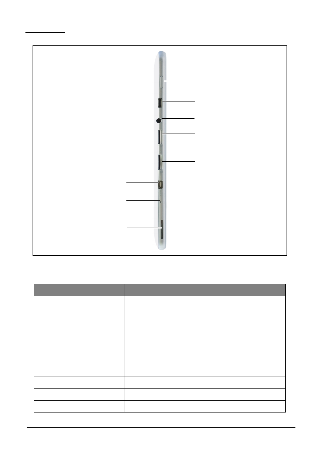
Left View
1
7
2
3
4
8
6
5
Figure 1-5. Right View
Table 1-5. Right View
# Item Description
• Press and hold to turn the tablet on or off.
1 Power Button
• Press briefly to turn the screen on/off or enter sleep
mode.
2 Micro-B USB Port
Connects to a computer or power adapter with a USB
cable.
3 Headset Jack Connects to stereo headphones.
4 Card Slot Insert a micro SD card into the slot.
5 Micro SIM slot Insert a micro SIM card into the slot.
6 Speakers Emits stereo audio.
7 Shutdown Key
Use to shutdown the device.
8 HDMI Slot Slot for HDMI compatible device conneciton.
Hardware Specifications and Configurations 1-9

System Block Diagram
PCM, UART3, EINT
MSDC3
CONN.
S501/S303
WIFI
BT4.0
GPS*
External Memory Interface
I2C, EINT
USB 2.0
Touch Sensor IC
S7300
micro USB, OTG
0.3M Camera
YUV,I2C
RGB
I2C,
EINT
Battery Input
Speaker
MT8193
MT6320
PMIC
AUDIO
LDO OUTPUT
BUCK OUTPUT
CHARGER
Battery
LDO Output
BUCK Output
I2S, SPI, EINT, I2C
eMMC
16G/32G
MSDC0 MSDC1
UART2
micro SD
UART4
JTAG
MT8389W
Cortex-A7
1.2GHz Quad-Core
Debug Port
DDR3L 1GB (4Gb X16 *2 Pcs)
UART1
LCM
26MHz
MIC
WIFI/BT
GPS
switching
Charger
I2C
SIM Card
MT6167
3G
GSM
BSI
3G SKU
GPIO
Gyro Sensor
MPU-6050
Vibrator
VIBR_PMU
MT3332
GLONASS
UART1, EINT
GPS
Russian Sku
CONN.
Capacitive
Touch Panel
KCOL & KROW
Sidekey (volume up/down)
5M Camera
MIPI,I2C
HDMI
P Sensor
IQS1280000
P Sensor
IQS1280000
HP
ALC105
1-10 Hardware Specifications and Configurations
Figure 1-6. System Block Diagram

Specifications Table
Computer specifications
Item Metric Imperial
Dimensions
Length 260 mm 10.24 in
Width 175 mm 6.89 in
Height (front to rear) 10.35 mm 0.41 in
Weight (equipped with optical
drive, flash drive, and battery)
Input power
Operating voltage AC Input: 100V ~ 240V / DC Output: 5.35V
Operating current AC Input: 0.3A / DC Output: 2.0A
Temperature
Operating -25º ~ 60ºC -13º ~ 140ºF
Non-operating -30º ~ 70ºC -22º ~ 158ºF
Relative humidity
Operating 5% ~ 90%
Non-operating 0% ~ 90%
Maximum altitude (unpressurized)
Operating 0 ~ 50 cm 0 ~ 1.97 in.
Non-operating
Shock
570g 1.26 lb
0cm-50 cm free drop on
wood
0cm-1.97 in. free drop on
wood
Operating Amplitude: 105G
Non-operating Amplitude: 220G
Random vibration
Operating 1.644 grms
Non-operating 1.644 grms
NOTE:
Applicable product safety standards specify thermal limits for plastic surfaces. The computer
operates well within this range of temperatures.
Hardware Specifications and Configurations 1-11

System Board Major Chips
Item Specification
MTK MT8389WK
CPU
AP MCU :
Quad-core ARM
®
Cortex-A7 MPCoreTM operating at 1.2GHz
Graphics Processor PowerVR™ SGX544MP1 Graphics accelerator
LVDS transmitter MTK MT8193A/B
PMU MTK MT6320GA/A
DDR3L DDR3L 1GB
ULPI Phy for USB N/A
Bluetooth AcSiP S501
Wireless AcSiP S501
GPS AcSiP S501
GPS Low-Noise Amplifier NXP_BGU7005
TOUCH controller Synaptics 324-000282-00R
eMMC 16G/32G
Front camera: 0.3MP Camera with Fix Focus (OV7675)
• Video capture recording at 30fps @ (640x480) VGA in MP4
CAMERA
format
Rear camera : 5MP Camera with Fix Focus (OV5648)
• Photo capture at 15fps @ 2592x1944 in JPEG
• Video capture recording at 30fps @ 1080p in MP4 format
Thermal Sensor N/A
Audio codec MTK _ MT6320GA/A (Embedded in PMU)
Audio Amplifier Realtek ALC105-GR
Echo Cancellation N/A
Battery Charger TI _ BQ24196RGER
Embedded Controller IC N/A
Compass N/A
Gyro Invensense MPU-6050
G-Sensor N/A
ALS/Proximity N/A
1-12 Hardware Specifications and Configurations

Processor
Item Specification
CPU MTK MT8389W
CPU package FCCSP_11.8mm*11.8mm*1.0mm_515 balls_pitch 0.4mm
Processor Specifications
Bus
Item
CPU
Speed
Cores
Speed
(FSB/
Mfg
Tech
Cache Size Package
Voltage
DMI/QBI)
• 32KB L1 I-
MT8389
1.2
GHz
Quad
Core
N/A 28nm
cache
• 32KB L1
D-cache
1MB unified
FCCSP_11.8
mm*11.8mm
*1.0mm_515
balls
1.05V
L2 cache
No CPU Fan for this product
No Graphics Controller
No BIOS Setup Menu for this product
No Keyboard for this product
Core
System Memory-DDR3L
Item Specification
Memory controller Embedded in CPU
Memory size DDR3L 1GB
System Memory-eMMC (Any conflict, the latest AVL shall prevail)
Item Specification
Vendor &
Model Name
Capacity
(GB)
Samsung
KLMAG2WE4A-
A001
16G 32G
Samsung
KLMBG4GEAC-
B001
DC Power Requirements
Voltage
tolerance
VCC: 3.3V
VCCQ: 1.8V
Hardware Specifications and Configurations 1-13

LAN Interface
Item Specification
LAN Chipset No support on board LAN
LAN connector type N/A
LAN connector location N/A
Bluetooth Interface
Item Specification
Chipset S501
Data throughput Bluetooth 2.1+EDR data rates of 1,2, and 3Mbps
Protocol TBD
Interface UART
Connector type I-PEX
Supported protocol TBD
Bluetooth Module
Item Specification
Controller UART interface
Features TBD
1-14 Hardware Specifications and Configurations
LED
Item Specification
Vendor/model name INX / N101ICG-L11
Screen Diagonal (mm) 255.85 (10.1")
Active Area (mm) 216.96(H) x 135.6(V)
Display resolution (pixels) 1280 x 3(RGB) x 800
Pixel Pitch (mm) 0.1695 X 0.1695
2
Typical White Luminance (cd/m
also called Brightness
)
350
Contrast Ratio 700
Response Time (Optical Rise
Time/Fall Time) msec
25
Typical Power Consumption (watt) 2.96 (max)
Weight (without inverter) 120 gr
Physical Size (mm) 227.42 x 147.69 x 4.36
Electrical Interface LVDS
Viewing Angle (degree)
Horizontal (Right) CR = 10 (Left)
• 85/85
• 85/85
Vertical (Upper) CR = 10 (Lower)
No LCD Inverter for this product
Display Supported Resolution (LCD Panel Supported Resolution)
Resolution 16 bits 32 bits 36 bits 48 bits others
1280x800p/60Hz 16:10 X X X X 18bits
Front Camera
Item Specification
Vendor and model
• Chicony CIFC01920004970LH
• Liteon 13P2SF001
Type 0.3M
Hardware Specifications and Configurations 1-15

Rear Camera
Item Specification
Vendor and model
• Chicony - CJFD51520004970LH
• Liteon - 13P2BF505
Type 5M
Mini Card
Item Specification
Number supported N/A
Features N/A
3G Card
Item Specification
Features N/A
Audio Codec Amplifier
Item Specification
Audio Controller MT6320
Audio onboard or optional On board
Mono or Stereo Mono
Resolution 24-bit data resolution
Compatibility I2S Interface;
Sampling rate Sample rate up to 44.1KHz
Internal microphone Yes
Internal speaker/quantity Yes / 0.5W stereo speakers x2
Phone Jack HP_Out + MIC
MT8125's Audio Function
• Sampling rates supported: 6kHz to 96kHz
• Sample formats supported: 8-bit/16-bit, Mono/Stereo
• Interfaces supported: DAI, I2S
• 4-band IIR compensation filter to enhance loudspeaker
responses
Features
• Proprietary audio post-processing technologies :
BesLoudness Android built-in post processing.
MT6320's Audio Codec Function
• Build in Audio Codec
• Full-set high-quality audio feature: Supports uplink/
downlink audio CODEC and high- power/quality audio
amplifier
1-16 Hardware Specifications and Configurations

Audio Codec Amplifier
Item Specification
Amplifier IC Realtek ALC105
The ALC105 is a stereo Class-D audio amplifier. In a 4 ohm
speaker impedance environment, with a 5V power supply,
maximum output power is 3W per channel. The ALC105
provides configurable input to output gain ratio, with no
external component requirement. For input signals, the
system designer can easily choose 11dB, 14dB,19dB, or
25dB boost gain by pulling high/low two control pins.
Features
With Class-D amplifier technology, the ALC105 has good
audio quality, high power efficiency, and fewer external
components. With analog input support, the ALC105 can also
be used as a Class-AB silicon, meaning less PCB area is
required to dissipate heat when driving output. This high
efficiency with less run-time power consumption can extend
the battery life for portable consumer electronic devices and
Notebook PCs.
Wireless Module 802.11b/g/n
Item Specification
Chipset S501
• 802.11b: 1, 2, 5.5, 11Mbps
Data throughput
• 802.11g: 6, 9, 12, 18, 24, 36, 48, 54Mbps
• 802.11n: MCS 0~7 HT20 HT40
Protocol CCXv2/CCXv3/CCXv4/CCXv5, WFAEC
Interface SDIO/SPI
Hardware Specifications and Configurations 1-17
Battery
Item Specification
Vendor & model name AP12D8K
Battery Type Li-polymer
Pack capacity 7300mAh(typical)
Number of battery cell 2cell
Package configuration 1S2P
Video Interface
Item Specification
Chipset N/A (Graphic function is embedded in CPU)
Package N/A
Interface N/A
Compatibility N/A
Sampling rate N/A
USB Port
Item Specification
USB compliance level USB2.0
Modes OTG
Speed Full and High
Number of USB port(s) 1 ports with OTG
Location JP11
Output Current 500mA (micro USB port , Device mode )
HDMI Port
Item Specification
Compliance level HDMI1.4
Data throughput D-Type
Number of HDMI port(s) 1
Location JP1
1-18 Hardware Specifications and Configurations

AC Adapter
Item Specification
Input rating 90~264Vac
Maximum input AC current 0.4A Max at 10W load and 100Vac input voltage
Inrush current
Efficiency
Card Reader
Item Specification
Chipset SD function is supported by CPU
Package N/A
Interface MSDC
Maximum supported size 32GB
Features MicroSD™
System LED Indicator
Item Specification
System state N/A ( No Indicator LED)
The cold inrush current must not cause the input fuse to open
or cause damage to component.
For inputs of 115Vac/60Hz and 230Vac/50Hz, average
efficiency at 25%, 50%, 75%, and full load shall be
≥
74.67%.
Hardware Specifications and Configurations 1-19

CHAPTER 2
Diagnostic Utilities
Diagnostic Utilities . . . . . . . . . . . . . . . . . . . . . . . . . . . . . . . . . . . . . . .2-2
Introduction . . . . . . . . . . . . . . . . . . . . . . . . . . . . . . . . . . . . . . . . . . . . . . . . . . . . 2-2
Diagnostic Tool SOP . . . . . . . . . . . . . . . . . . . . . . . . . . . . . . . . . . . . . . . . . . . . 2-2
Main Menu . . . . . . . . . . . . . . . . . . . . . . . . . . . . . . . . . . . . . . . . . . . . . . . . . 2-3
Testing User Interface (UI) . . . . . . . . . . . . . . . . . . . . . . . . . . . . . . . . . . . . . 2-3
Test Report UI . . . . . . . . . . . . . . . . . . . . . . . . . . . . . . . . . . . . . . . . . . . . . . 2-4
CSD DL Tool . . . . . . . . . . . . . . . . . . . . . . . . . . . . . . . . . . . . . . . . . . . . . . . . . . . 2-9
Preparation . . . . . . . . . . . . . . . . . . . . . . . . . . . . . . . . . . . . . . . . . . . . . . . . . 2-9
Using the CSD DL Tool . . . . . . . . . . . . . . . . . . . . . . . . . . . . . . . . . . . . . . 2-11
NVRAM Writer Tool . . . . . . . . . . . . . . . . . . . . . . . . . . . . . . . . . . . . . . . . . . . . 2-13
Preparation . . . . . . . . . . . . . . . . . . . . . . . . . . . . . . . . . . . . . . . . . . . . . . . . 2-13
Using the NVRAM Writer Tool . . . . . . . . . . . . . . . . . . . . . . . . . . . . . . . . . 2-16
G-Sensor Calibration Tool . . . . . . . . . . . . . . . . . . . . . . . . . . . . . . . . . . . . . . . 2-19
Preparation . . . . . . . . . . . . . . . . . . . . . . . . . . . . . . . . . . . . . . . . . . . . . . . . 2-19
Using the G-Sensor Calibration Tool . . . . . . . . . . . . . . . . . . . . . . . . . . . . 2-22

Diagnostic Utilities
ACTP
Introduction
The A3-A11 has a software tool designed to diagnose problems with its hardware components.
Diagnostic Tool SOP
1. On the device, go to the applications screen and look for the diagnostic tool named ACTP.
Figure 2-1. Device Applications Screen
2. Tap the ACTP icon to start the testing process.
Diagnostic Utilities 2-2

Main Menu
The diagnostic tool tests the functions of TouchSlope, Double Touch, RGB, HW Keys, Front
Camera, Speaker, Top Mic, SD Card and G-sensor.
Select the function(s) you want to test, and then tap OK to start.
Figure 2-2. Diagnostic Tool Main Menu
Testing User Interface (UI)
• Test items status window: At the left side of the UI. It displays the status of the test item.
• The main test window: A direction window to tell user to take an action as displayed on the screen.
• To exit the test window, long press the ACTP logo at the left side of the screen.
Figure 2-3. Testing UI
2-3 Diagnostic Utilities

Test Report UI
After the text, the result will be displayed on the screen. The 4 colors indicate the status of the test
as follows:
NOTE:
• Long press any color button to retest the single item.
• Long press yellow item to exit the background test.
• Press “Exit” to exit ACTP.
• Press
• Green: Means the test item passed.
• Red: Means the test item failed.
• Yellow: Means the test item still been testing at background.
• Grey: Means not tested items.
“Retest” to retest the failed and non-tested items.
1. TouchSlope Test
Draw a line from the top left corner to the bottom right corner on the screen.
Draw a line from the top right corner to the bottom left corner on the screen.
Draw each line three (3) times. If drawing fails for more than 3 times, the TouchSlope Test will fail.
Figure 2-4. TouchSlope Test
Diagnostic Utilities 2-4

2. Double Touch Test
The Double Touch Test is used to test 2 points touch on the panel.
Use two (2) fingers to draw from the left to the right along the blue bars.
When the top bars has been drawn successfully, continue to draw on the blue bars on the right,
then on the bottom and on the left.
Each side must be drawn three (3) times. If drawing fails for more than three (3) times, the Double
Touch Test will fail.
Figure 2-5. Double Touch Test
3. RGB Test
Press Vol + hardware key to start the test. Press Vol - hardware key to switch to the next
colored screen.
The screen sequence are as follows: Red-Green-Blue-Black-White.
Judge the test result by tapping the “Pass” or “Failure” button. Or, press the “Retest” button to
do the retest.
Figure 2-6. RGB Test
2-5 Diagnostic Utilities
 Loading...