

Page 1

Picasso
SERVICE GUIDE
Page 2

Revision History
Refer to the table below for the updates made to this service guide.
Date Chapter Updates
Service guide files and updates are available on the ACER/CSD Website. For more
information, go to http://csd.acer.com.tw
without notice.
.The information in this guide is subject to change
Copyright
Copyright © 2011 by Acer Incorporated. All rights reserved. No part of this publication may be
reproduced, transmitted, transcribed, stored in a retrieval system, or translated into any
language or computer language, in any form or by any means, electronic, mechanical,
magnetic, optical, chemical, manual or otherwise, without the prior written permission of Acer
Incorporated.
Disclaimer
The information in this guide is subject to change without notice.
There are no representations or warranties, either expressed or implied, with respect to the
contents hereof and specifically disclaims any warranties of merchantability or fitness for any
particular purpose. The software described in this manual is sold or licensed "as is". Should
the programs prove defective following their pur ch as e, th e bu ye r (n ot the ma n uf ac tur e r,
distributor, or its dealer) assumes the entire cost of all necessary servicing, repair, and any
incidental or consequential damages resulting from any defect in the software.
ii
Page 3

Conventions
NOTE
The following conventions are used in this manual:
!
WARNING:
Indicates a potential for personal injury.
!
CAUTION:
Indicates a potential loss of data or damage to equipment.
IMPORTANT:
+
Indicates information that is important to know for the proper completion of a
procedure, choice of an option, or completing a task.
NOTE:
:
Follow local regulations for battery and circuit board disposal. Batteries and Circuit
Boards >10 cm² have been highlighted with a yellow rectangle.
The following typographical conventions are used in this document:
Book titles, directory names, file names, path names, and program/process names are
shown in italics.
Example:
the DRS5 User's Guide
/usr/local/bin/fd
the /TPH15spool_M program
Computer output (text that represents information displayed on a computer screen,
such as menus, prompts, responses to input, and error messages) are shown in
constant width.
Example:
[01] The server has been stopped
User input (text that represents information entered by a computer user, such as
command names, option letters, and words) are shown in constant width bold.
Variables contained within user input are shown in angle brackets (< >).
Example:
At the prompt, type run <file name> -m
Keyboard keys are shown in bold italics.
Example:
After entering data, press Enter.
iii
Page 4

General Information 0
This service guide provides all technical information relating to the basic configuration for Acer
global product offering. To better fit local market requirements and enhance product
competitiveness, your regional office may have decided to extend the functionality of a
machine (such as add-on cards, modems, or extra memory capabilities). These localized
features are not covered in this generic service guide. In such cases, contact your regional
offices or the responsible personnel/channel to provide further technical details.
When ordering FRU parts:
Check the most up-to-date information available on your regional Web or channel. If, for
whatever reason, a part number change is made, it may not be noted in this printed service
guide.
Acer-authorized Service Providers:
Your Acer office may have a differ ent part num ber code than those given in the FRU list in this
service guide. The list provided by your regional Acer office must be used to order FRU parts
for repair and service of customer machines.
iv
Page 5

CHAPTER 1
Hardware Specifications
Features . . . . . . . . . . . . . . . . . . . . . . . . . . . . . . . . . . . . . . . . . . . .1-5
Form Factor. . . . . . . . . . . . . . . . . . . . . . . . . . . . . . . . . . . . . . . 1-5
CPU . . . . . . . . . . . . . . . . . . . . . . . . . . . . . . . . . . . . . . . . . . . . . 1-5
Memory. . . . . . . . . . . . . . . . . . . . . . . . . . . . . . . . . . . . . . . . . . 1-5
LCM . . . . . . . . . . . . . . . . . . . . . . . . . . . . . . . . . . . . . . . . . . . . . 1-5
Network . . . . . . . . . . . . . . . . . . . . . . . . . . . . . . . . . . . . . . . . . 1-5
GPS/A GPS . . . . . . . . . . . . . . . . . . . . . . . . . . . . . . . . . . . . . . . . 1-5
Camera . . . . . . . . . . . . . . . . . . . . . . . . . . . . . . . . . . . . . . . . . . 1-6
Connectivity . . . . . . . . . . . . . . . . . . . . . . . . . . . . . . . . . . . . . . 1-6
Input . . . . . . . . . . . . . . . . . . . . . . . . . . . . . . . . . . . . . . . . . . . . 1-6
Output. . . . . . . . . . . . . . . . . . . . . . . . . . . . . . . . . . . . . . . . . . . 1-6
Audio. . . . . . . . . . . . . . . . . . . . . . . . . . . . . . . . . . . . . . . . . . . . 1-6
Operation System. . . . . . . . . . . . . . . . . . . . . . . . . . . . . . . . . . 1-6
Dimension and Weight . . . . . . . . . . . . . . . . . . . . . . . . . . . . . 1-6
Expansion Slot . . . . . . . . . . . . . . . . . . . . . . . . . . . . . . . . . . . . 1-7
AC Adapter and Battery. . . . . . . . . . . . . . . . . . . . . . . . . . . . . 1-7
Green Requirement . . . . . . . . . . . . . . . . . . . . . . . . . . . . . . . . 1-7
Others . . . . . . . . . . . . . . . . . . . . . . . . . . . . . . . . . . . . . . . . . . . 1-7
Accessory. . . . . . . . . . . . . . . . . . . . . . . . . . . . . . . . . . . . . . . . . 1-7
Notebook Tour . . . . . . . . . . . . . . . . . . . . . . . . . . . . . . . . . . . . . . .1-8
Front View . . . . . . . . . . . . . . . . . . . . . . . . . . . . . . . . . . . . . . . 1-8
Rear View . . . . . . . . . . . . . . . . . . . . . . . . . . . . . . . . . . . . . . . . 1-9
Top View. . . . . . . . . . . . . . . . . . . . . . . . . . . . . . . . . . . . . . . . . 1-10
Left View. . . . . . . . . . . . . . . . . . . . . . . . . . . . . . . . . . . . . . . . . 1-11
Right View . . . . . . . . . . . . . . . . . . . . . . . . . . . . . . . . . . . . . . . 1-12
Bottom View. . . . . . . . . . . . . . . . . . . . . . . . . . . . . . . . . . . . . . 1-13
System Block Diagram . . . . . . . . . . . . . . . . . . . . . . . . . . . . . . . . .1-14
Specification Tables . . . . . . . . . . . . . . . . . . . . . . . . . . . . . . . . . . .1-15
Computer specifications . . . . . . . . . . . . . . . . . . . . . . . . . . . . . 1-15
System Board Major Chips . . . . . . . . . . . . . . . . . . . . . . . . . . . 1-16
Processor. . . . . . . . . . . . . . . . . . . . . . . . . . . . . . . . . . . . . . . . . 1-16
Processor Specifications . . . . . . . . . . . . . . . . . . . . . . . . . . . . . 1-17
System Memory. . . . . . . . . . . . . . . . . . . . . . . . . . . . . . . . . . . . 1-17
Memory Combinations. . . . . . . . . . . . . . . . . . . . . . . . . . . . . . . 1-18
Video Interface. . . . . . . . . . . . . . . . . . . . . . . . . . . . . . . . . . . . . 1-18
Embedded MultiMediaCard (AVL components) . . . . . . . . . . . 1-21
LED 10.1”. . . . . . . . . . . . . . . . . . . . . . . . . . . . . . . . . . . . . . . . . 1-22
Display Supported Resolution (LCD). . . . . . . . . . . . . . . . . . . . 1-23
Display Supported Resolution (GPU) . . . . . . . . . . . . . . . . . . . 1-23
Bluetooth Interface. . . . . . . . . . . . . . . . . . . . . . . . . . . . . . . . . . 1-23
Bluetooth Module. . . . . . . . . . . . . . . . . . . . . . . . . . . . . . . . . . . 1-23
Front Camera. . . . . . . . . . . . . . . . . . . . . . . . . . . . . . . . . . . . . . 1-24
v
Page 6

Rear Camera. . . . . . . . . . . . . . . . . . . . . . . . . . . . . . . . . . . . . . 1-24
Mini Card . . . . . . . . . . . . . . . . . . . . . . . . . . . . . . . . . . . . . . . . . 1-24
3G Card. . . . . . . . . . . . . . . . . . . . . . . . . . . . . . . . . . . . . . . . . . 1-24
Audio Codec and Amplifier . . . . . . . . . . . . . . . . . . . . . . . . . . . 1-25
Audio Interface. . . . . . . . . . . . . . . . . . . . . . . . . . . . . . . . . . . . . 1-25
Wireless Module 802.11b/g/n . . . . . . . . . . . . . . . . . . . . . . . . . 1-26
Battery . . . . . . . . . . . . . . . . . . . . . . . . . . . . . . . . . . . . . . . . . . . 1-26
VRAM . . . . . . . . . . . . . . . . . . . . . . . . . . . . . . . . . . . . . . . . . . . 1-26
USB Port . . . . . . . . . . . . . . . . . . . . . . . . . . . . . . . . . . . . . . . . . 1-26
HDMI Port . . . . . . . . . . . . . . . . . . . . . . . . . . . . . . . . . . . . . . . . 1-26
AC Adapter . . . . . . . . . . . . . . . . . . . . . . . . . . . . . . . . . . . . . . . 1-27
System Power Management . . . . . . . . . . . . . . . . . . . . . . . . . . 1-27
Card Reader . . . . . . . . . . . . . . . . . . . . . . . . . . . . . . . . . . . . . . 1-27
System LED Indicator . . . . . . . . . . . . . . . . . . . . . . . . . . . . . . . 1-27
System DMA Specification . . . . . . . . . . . . . . . . . . . . . . . . . . . 1-28
CHAPTER 2
System Utilities
Introduction . . . . . . . . . . . . . . . . . . . . . . . . . . . . . . . . . . . . . . . . .2-3
CHAPTER 3
Maintenance Procedures
Introduction . . . . . . . . . . . . . . . . . . . . . . . . . . . . . . . . . . . . . . . . .3-3
General Information . . . . . . . . . . . . . . . . . . . . . . . . . . . . . . . . . .3-3
Recommended Equipment . . . . . . . . . . . . . . . . . . . . . . . . . . . . .3-3
Maintenance Flowchart. . . . . . . . . . . . . . . . . . . . . . . . . . . . . . . .3-4
Getting Started . . . . . . . . . . . . . . . . . . . . . . . . . . . . . . . . . . . . . .3-5
SIM/Micro-SD Card Removal . . . . . . . . . . . . . . . . . . . . . . . . . 3-6
SIM/Micro-SD Card Installation . . . . . . . . . . . . . . . . . . . . . . . 3-8
Lower Case Removal . . . . . . . . . . . . . . . . . . . . . . . . . . . . . . . 3-9
Lower Case Installation . . . . . . . . . . . . . . . . . . . . . . . . . . . . . 3-12
DC-In Cable Removal . . . . . . . . . . . . . . . . . . . . . . . . . . . . . . . 3-17
DC-In Cable Installation . . . . . . . . . . . . . . . . . . . . . . . . . . . . . 3-19
Battery Removal. . . . . . . . . . . . . . . . . . . . . . . . . . . . . . . . . . . 3-20
Battery Installation. . . . . . . . . . . . . . . . . . . . . . . . . . . . . . . . . 3-21
3G Module Removal. . . . . . . . . . . . . . . . . . . . . . . . . . . . . . . . 3-22
3G Module Installation . . . . . . . . . . . . . . . . . . . . . . . . . . . . . 3-24
Docking Board Removal. . . . . . . . . . . . . . . . . . . . . . . . . . . . . 3-25
Docking Board Installation . . . . . . . . . . . . . . . . . . . . . . . . . . 3-28
GPS Antenna Removal . . . . . . . . . . . . . . . . . . . . . . . . . . . . . . 3-29
GPS Antenna Installation. . . . . . . . . . . . . . . . . . . . . . . . . . . . 3-30
vi
Page 7

Mainboard Removal. . . . . . . . . . . . . . . . . . . . . . . . . . . . . . . . 3-31
Mainboard Installation . . . . . . . . . . . . . . . . . . . . . . . . . . . . . 3-33
Rear CCD Removal . . . . . . . . . . . . . . . . . . . . . . . . . . . . . . . . . 3-36
Rear CCD Installation . . . . . . . . . . . . . . . . . . . . . . . . . . . . . . . 3-38
Front CCD Removal . . . . . . . . . . . . . . . . . . . . . . . . . . . . . . . . 3-39
Front CCD Installation . . . . . . . . . . . . . . . . . . . . . . . . . . . . . . 3-39
Two-Piece Microphone Removal. . . . . . . . . . . . . . . . . . . . . . 3-40
Two-Piece Microphone Installation. . . . . . . . . . . . . . . . . . . . 3-41
Speakers Removal. . . . . . . . . . . . . . . . . . . . . . . . . . . . . . . . . . 3-42
Speakers Installation . . . . . . . . . . . . . . . . . . . . . . . . . . . . . . . 3-42
USB Module Removal. . . . . . . . . . . . . . . . . . . . . . . . . . . . . . . 3-43
USB Module Installation . . . . . . . . . . . . . . . . . . . . . . . . . . . . 3-44
LCD Support Plate Removal. . . . . . . . . . . . . . . . . . . . . . . . . . 3-46
LCD Support Plate Installation. . . . . . . . . . . . . . . . . . . . . . . . 3-49
Touch Screen Board Removal . . . . . . . . . . . . . . . . . . . . . . . . 3-50
Touch Screen Board Installation . . . . . . . . . . . . . . . . . . . . . . 3-51
3G Antenna Removal. . . . . . . . . . . . . . . . . . . . . . . . . . . . . . . 3-53
3G Antenna Installation. . . . . . . . . . . . . . . . . . . . . . . . . . . . . 3-53
WLAN Antenna Removal. . . . . . . . . . . . . . . . . . . . . . . . . . . . 3-55
WLAN Antenna Installation. . . . . . . . . . . . . . . . . . . . . . . . . . 3-56
CHAPTER 4
Troubleshooting
Introduction . . . . . . . . . . . . . . . . . . . . . . . . . . . . . . . . . . . . . . . . .4-3
General Information . . . . . . . . . . . . . . . . . . . . . . . . . . . . . . . . . .4-3
Power On Issues . . . . . . . . . . . . . . . . . . . . . . . . . . . . . . . . . . . 4-4
No Display Issues. . . . . . . . . . . . . . . . . . . . . . . . . . . . . . . . . . . 4-5
LCD Picture Failure. . . . . . . . . . . . . . . . . . . . . . . . . . . . . . . . . 4-6
Touch Screen Failure . . . . . . . . . . . . . . . . . . . . . . . . . . . . . . . 4-7
Internal Speaker Failure. . . . . . . . . . . . . . . . . . . . . . . . . . . . . 4-8
Internal Microphone Failure . . . . . . . . . . . . . . . . . . . . . . . . . 4-9
USB Failure . . . . . . . . . . . . . . . . . . . . . . . . . . . . . . . . . . . . . . . 4-10
Front Camera Failure . . . . . . . . . . . . . . . . . . . . . . . . . . . . . . . 4-11
Back Camera Failure. . . . . . . . . . . . . . . . . . . . . . . . . . . . . . . . 4-12
P-Sensor Failure . . . . . . . . . . . . . . . . . . . . . . . . . . . . . . . . . . . 4-13
3G Function Failure . . . . . . . . . . . . . . . . . . . . . . . . . . . . . . . . 4-14
Wireless Function Test Failure. . . . . . . . . . . . . . . . . . . . . . . . 4-15
GPS Function Test Failure (Wi-Fi SKU). . . . . . . . . . . . . . . . . . 4-16
GPS Function Test Failure (3G SKU). . . . . . . . . . . . . . . . . . . . 4-17
Docking Station Test Failure . . . . . . . . . . . . . . . . . . . . . . . . . 4-18
Other Functions Failure . . . . . . . . . . . . . . . . . . . . . . . . . . . . . 4-19
vii
Page 8

CHAPTER 5
Jumper and Connector Locations
Mainboard . . . . . . . . . . . . . . . . . . . . . . . . . . . . . . . . . . . . . . . . . .5-3
CHAPTER 6
Field Replaceable Unit List
Exploded Diagrams . . . . . . . . . . . . . . . . . . . . . . . . . . . . . . . . . . .6-4
Main Assembly . . . . . . . . . . . . . . . . . . . . . . . . . . . . . . . . . . . . 6-4
FRU List. . . . . . . . . . . . . . . . . . . . . . . . . . . . . . . . . . . . . . . . . . . . .6-8
Screw List . . . . . . . . . . . . . . . . . . . . . . . . . . . . . . . . . . . . . . . . . . .6-12
CHAPTER 7
Model Definition and Configuration
A500 . . . . . . . . . . . . . . . . . . . . . . . . . . . . . . . . . . . . . . . . . . . . . . .7-3
A501 . . . . . . . . . . . . . . . . . . . . . . . . . . . . . . . . . . . . . . . . . . . . . . .7-12
CHAPTER 8
Test Compatible Components
Android OS Environment Test. . . . . . . . . . . . . . . . . . . . . . . . . . .8-4
ICONIA Tablet A500/501 . . . . . . . . . . . . . . . . . . . . . . . . . . . . 8-4
CHAPTER 9
Online Support Information
Introduction . . . . . . . . . . . . . . . . . . . . . . . . . . . . . . . . . . . . . . . . .9-3
viii
Page 9

CHAPTER 1
Hardware Specifications
Page 10

Features . . . . . . . . . . . . . . . . . . . . . . . . . . . . . . . . . . . . . . . . . . . .1-5
Form Factor. . . . . . . . . . . . . . . . . . . . . . . . . . . . . . . . . . . . . . . 1-5
CPU . . . . . . . . . . . . . . . . . . . . . . . . . . . . . . . . . . . . . . . . . . . . . 1-5
Memory. . . . . . . . . . . . . . . . . . . . . . . . . . . . . . . . . . . . . . . . . . 1-5
LCM . . . . . . . . . . . . . . . . . . . . . . . . . . . . . . . . . . . . . . . . . . . . . 1-5
Network . . . . . . . . . . . . . . . . . . . . . . . . . . . . . . . . . . . . . . . . . 1-5
GPS/A GPS . . . . . . . . . . . . . . . . . . . . . . . . . . . . . . . . . . . . . . . . 1-5
Camera . . . . . . . . . . . . . . . . . . . . . . . . . . . . . . . . . . . . . . . . . . 1-6
Connectivity . . . . . . . . . . . . . . . . . . . . . . . . . . . . . . . . . . . . . . 1-6
Input . . . . . . . . . . . . . . . . . . . . . . . . . . . . . . . . . . . . . . . . . . . . 1-6
Output. . . . . . . . . . . . . . . . . . . . . . . . . . . . . . . . . . . . . . . . . . . 1-6
Audio. . . . . . . . . . . . . . . . . . . . . . . . . . . . . . . . . . . . . . . . . . . . 1-6
Operation System. . . . . . . . . . . . . . . . . . . . . . . . . . . . . . . . . . 1-6
Dimension and Weight . . . . . . . . . . . . . . . . . . . . . . . . . . . . . 1-6
Expansion Slot . . . . . . . . . . . . . . . . . . . . . . . . . . . . . . . . . . . . 1-7
AC Adapter and Battery. . . . . . . . . . . . . . . . . . . . . . . . . . . . . 1-7
Green Requirement . . . . . . . . . . . . . . . . . . . . . . . . . . . . . . . . 1-7
Others . . . . . . . . . . . . . . . . . . . . . . . . . . . . . . . . . . . . . . . . . . . 1-7
Accessory. . . . . . . . . . . . . . . . . . . . . . . . . . . . . . . . . . . . . . . . . 1-7
Notebook Tour . . . . . . . . . . . . . . . . . . . . . . . . . . . . . . . . . . . . . . .1-8
Front View . . . . . . . . . . . . . . . . . . . . . . . . . . . . . . . . . . . . . . . 1-8
Rear View . . . . . . . . . . . . . . . . . . . . . . . . . . . . . . . . . . . . . . . . 1-9
Top View. . . . . . . . . . . . . . . . . . . . . . . . . . . . . . . . . . . . . . . . . 1-10
Left View. . . . . . . . . . . . . . . . . . . . . . . . . . . . . . . . . . . . . . . . . 1-11
Right View . . . . . . . . . . . . . . . . . . . . . . . . . . . . . . . . . . . . . . . 1-12
Bottom View. . . . . . . . . . . . . . . . . . . . . . . . . . . . . . . . . . . . . . 1-13
System Block Diagram . . . . . . . . . . . . . . . . . . . . . . . . . . . . . . . . .1-14
Specification Tables . . . . . . . . . . . . . . . . . . . . . . . . . . . . . . . . . . .1-15
Computer specifications . . . . . . . . . . . . . . . . . . . . . . . . . . . . . 1-15
Processor. . . . . . . . . . . . . . . . . . . . . . . . . . . . . . . . . . . . . . . . . 1-16
Processor Specifications . . . . . . . . . . . . . . . . . . . . . . . . . . . . . 1-17
System Memory. . . . . . . . . . . . . . . . . . . . . . . . . . . . . . . . . . . . 1-17
Video Interface. . . . . . . . . . . . . . . . . . . . . . . . . . . . . . . . . . . . . 1-18
Display Supported Resolution (GPU) . . . . . . . . . . . . . . . . . . . 1-23
Bluetooth Interface. . . . . . . . . . . . . . . . . . . . . . . . . . . . . . . . . . 1-23
Bluetooth Module. . . . . . . . . . . . . . . . . . . . . . . . . . . . . . . . . . . 1-23
Rear Camera. . . . . . . . . . . . . . . . . . . . . . . . . . . . . . . . . . . . . . 1-24
Mini Card . . . . . . . . . . . . . . . . . . . . . . . . . . . . . . . . . . . . . . . . . 1-24
3G Card. . . . . . . . . . . . . . . . . . . . . . . . . . . . . . . . . . . . . . . . . . 1-24
Audio Interface. . . . . . . . . . . . . . . . . . . . . . . . . . . . . . . . . . . . . 1-25
Battery . . . . . . . . . . . . . . . . . . . . . . . . . . . . . . . . . . . . . . . . . . . 1-26
VRAM . . . . . . . . . . . . . . . . . . . . . . . . . . . . . . . . . . . . . . . . . . . 1-26
USB Port . . . . . . . . . . . . . . . . . . . . . . . . . . . . . . . . . . . . . . . . . 1-26
HDMI Port . . . . . . . . . . . . . . . . . . . . . . . . . . . . . . . . . . . . . . . . 1-26
AC Adapter . . . . . . . . . . . . . . . . . . . . . . . . . . . . . . . . . . . . . . . 1-27
System Power Management . . . . . . . . . . . . . . . . . . . . . . . . . . 1-27
1-2
Page 11

Card Reader . . . . . . . . . . . . . . . . . . . . . . . . . . . . . . . . . . . . . . 1-27
System LED Indicator . . . . . . . . . . . . . . . . . . . . . . . . . . . . . . . 1-27
System DMA Specification . . . . . . . . . . . . . . . . . . . . . . . . . . . 1-28
1-3
Page 12

1-4
Page 13

Hardware Specifications and Configurations
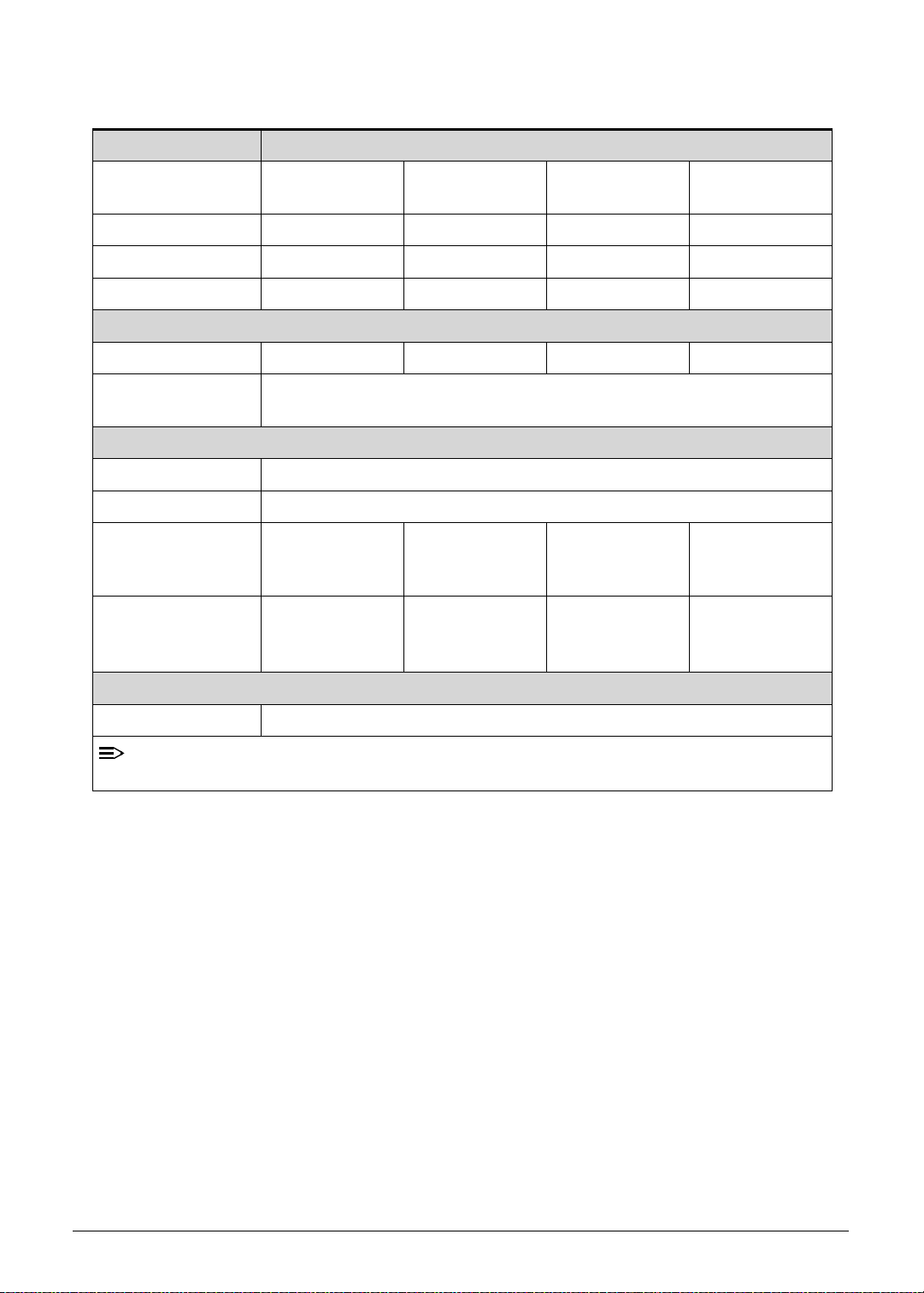
Features 0
The following is a summary of the computer’s many features:
Form Factor 0
10.1" Tablet
CPU 0
Tegra 250 Dual cortex A9, 1GHz
GPU Ultra Low Power GeForce
Memory 0
RAM: LP DDR2 1GB
eMMC: eMMC: 16G / 32G two SKU (SanDisk / Samsung)
LCM 0
10.1" WXGA LCM (1280*800 AUO)
Wide view angle
LVDS interface
®
GPU
Network 0
G Module HUAWEI EM770W (with GPS/AGPS)
UMTS /WCDMA 1, 2, 5, 8 2100/1900/850/900
HSPA : HSDPA up to 7.2 Mbps/ HSUPA up to 5.76Mbps
GSM/GPRS/EDGE 850MHz / 900MHz / 1800Mhz / 1900Mhz
3G Module Erisson F5521gw (with GPS/AGPS)
UMTS /WCDMA 1, 2, 5, 8 2100/1900/850/900
HSPA+ : HSDPA up to 21Mbps/ HSUPA up to 5.76Mbps
GSM/GPRS/EDGE 850MHz / 900MHz / 1800Mhz / 1900Mhz
3G Module HUAWEI EM820W (with GPS/AGPS)
UMTS /WCDMA 1, 2, 5, 8 2100/1900/850/900
HSPA+ : HSDPA up to 21Mbps / HSUPA up to 5.76Mbps
GSM/GPRS/EDGE 850MHz / 900MHz / 1800Mhz / 1900Mhz
GPS/A GPS 0
WIFI SKU : Broadcom - stand alone, not support A-GPS
3G SKU : on 3G module, support GPS and A-GPS
Hardware Specifications and Configurations 1-5
Page 14

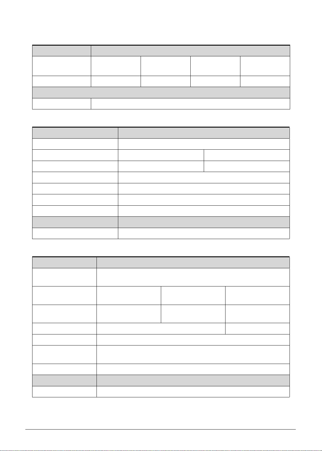
Camera 0
Main camera: 5M Camera with Auto focus
with flash lights (single LED)
Second camera : 2M FF
Connectivity 0
Bluetooth
Wi-Fi IEEE 802.11b/g/n (2.4Ghz)
USB
Micro USB 2.0 type B for Client
USB 2.0 Host
®
2.1+EDR
Input 0
Capacitive Multi-Touch Screen (Real 4 touch, up to 10)
Function buttons
Side (mechanical key):
Volume Up, Volume Down, screen lock
Power: with back light-white/orange
Sensors
G-Sensor
E-Compass
L Sensor
Gyro-meter
Output 0
HDMI D-type (support Dual Display)
Audio 0
Dual analog Microphone (Beam-forming, Noise /echo cancellation)
Dual Speaker
3.5mm Audio Jack 4ring (with Mic)
Dolby mobile
Operation System 0
Android Honeycomb
Dimension and Weight 0
Dimensions
260 (L) x 177 (W) x 13.3 (H) mm
Weight
WIFI SKU: <765g
3G SKU: <777g
1-6 Hardware Specifications and Configurations
Page 15

Expansion Slot 0
NOTE
MicroSD memory card up to 32G (SDHC 2.0 compatible)
AC Adapter and Battery 0
Battery
Rechargeable Lithium-ion polymer battery
Capacity: 24.1W (3260mAh cell , 2S1P)
AC Adapter
Voltage range/frequency: 100 ~ 240V AC, 50/60 Hz
DC output: 12V and 1.5 A, 18W
Green Requirement 0
Rohs compliance
WEEE compliance
Hologen free, at least PVC free
SMT Green process
Others 0
Reset hole
Docking (Support Charging , Audio out and IR remote control, not support HDMI)
Accessory 0
In Box
USB Cable
Charger + Plug
QSG
NOTE:
:
will not have protective film
Optional
Micro SD Card
Dock with IR remote control
HDMI Cable
Pouch
Hardware Specifications and Configurations 1-7
Page 16
Notebook Tour 0
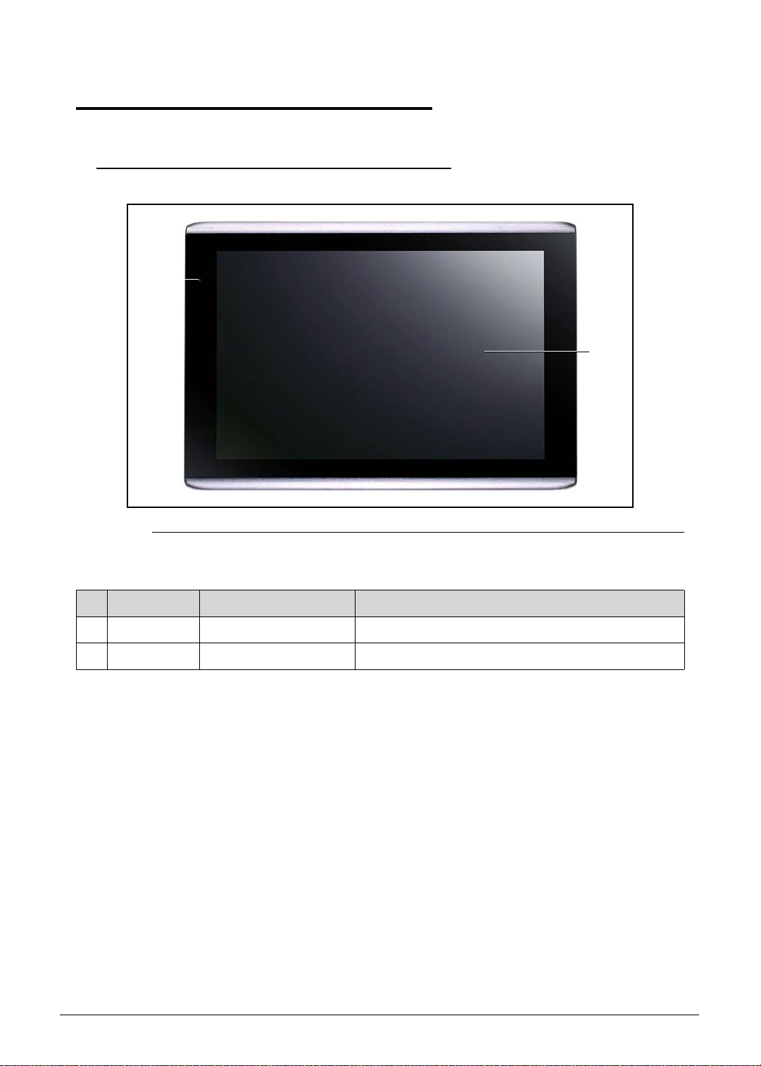
Front View 0
1
2
Figure 1-1. Front View
Table 1-1. Front View
# Icon Item Description
1 Front Camera 5M Pixel CCD
2 Touch Window
1-8 Hardware Specifications and Configurations
Page 17
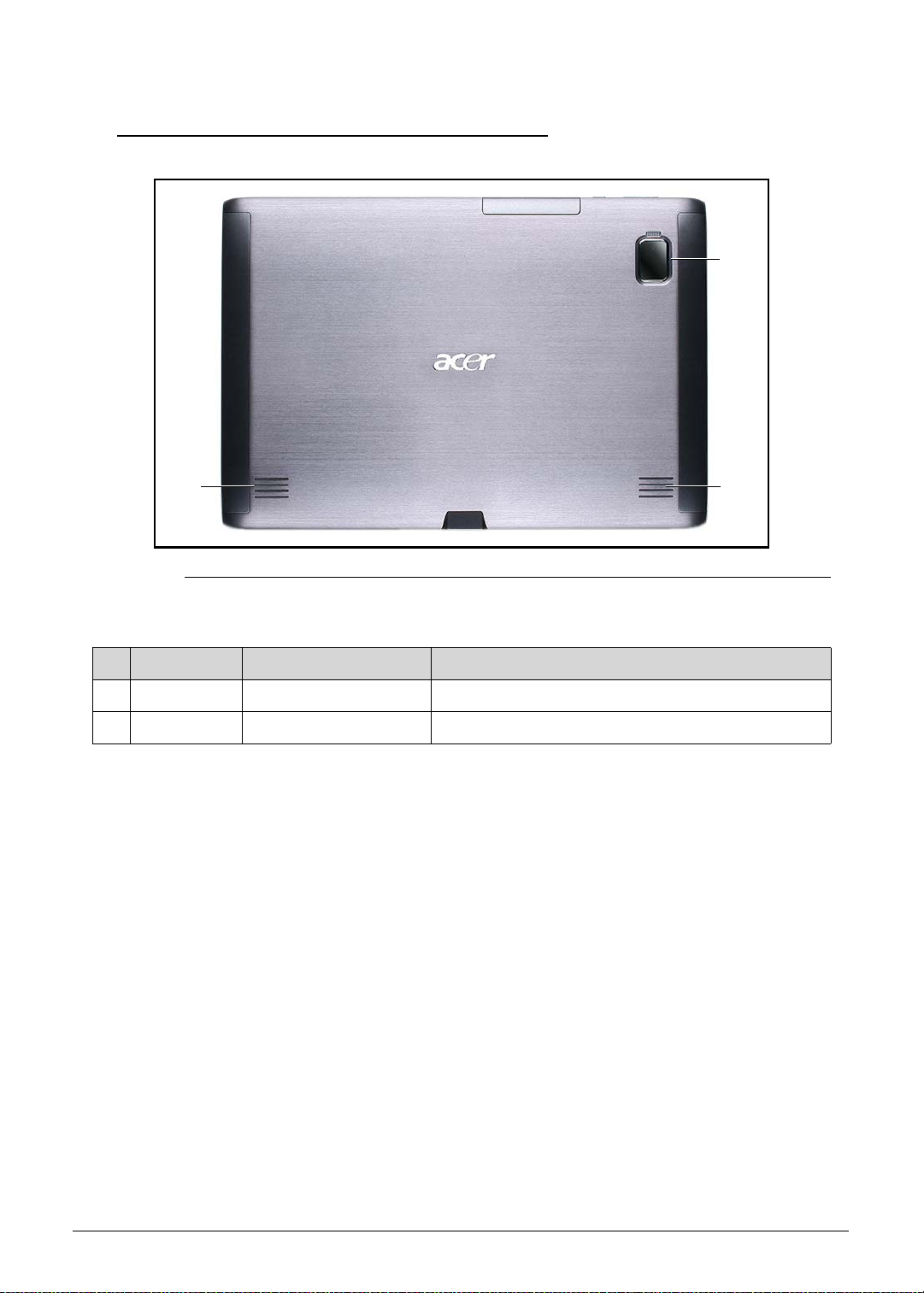
Rear View 0
1
2
Figure 1-2. Front View
Table 1-2. Front View
# Icon Item Description
1 2M Pixel CCD & LED
22 Speakers
2
Hardware Specifications and Configurations 1-9
Page 18
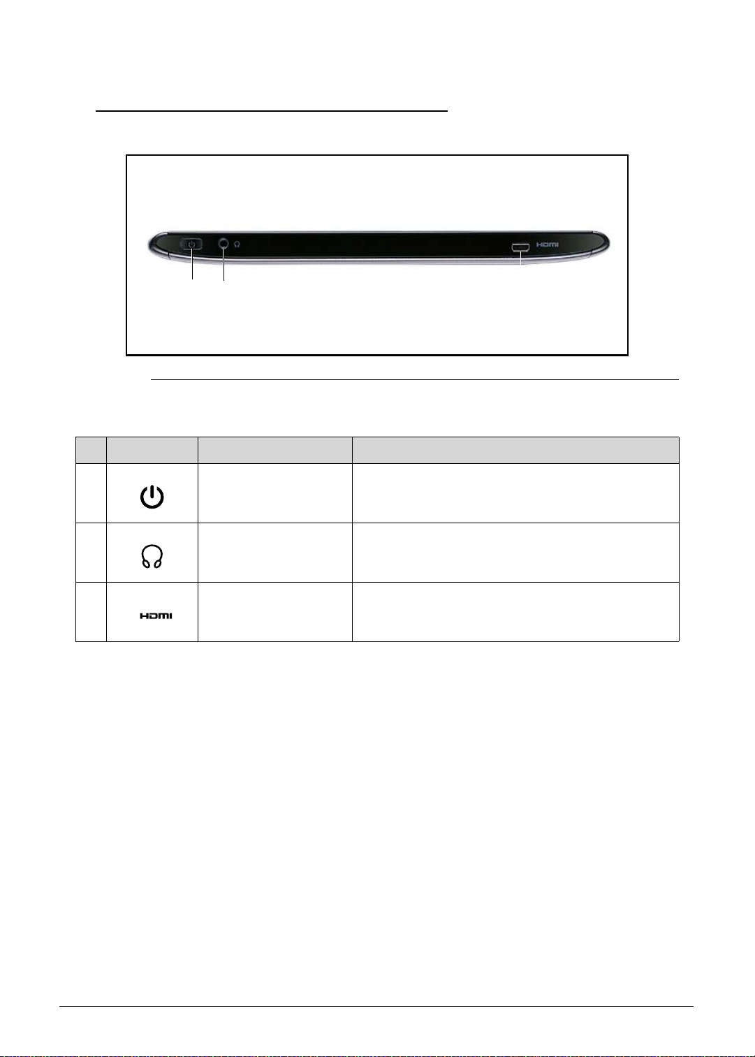
Top View 0
1 2 3
Figure 1-3. Top View
Table 1-3. Top View
# Icon Item Description
1 Power Button
2 Headset Jack
3 HDMI Jack
1-10 Hardware Specifications and Configurations
Page 19
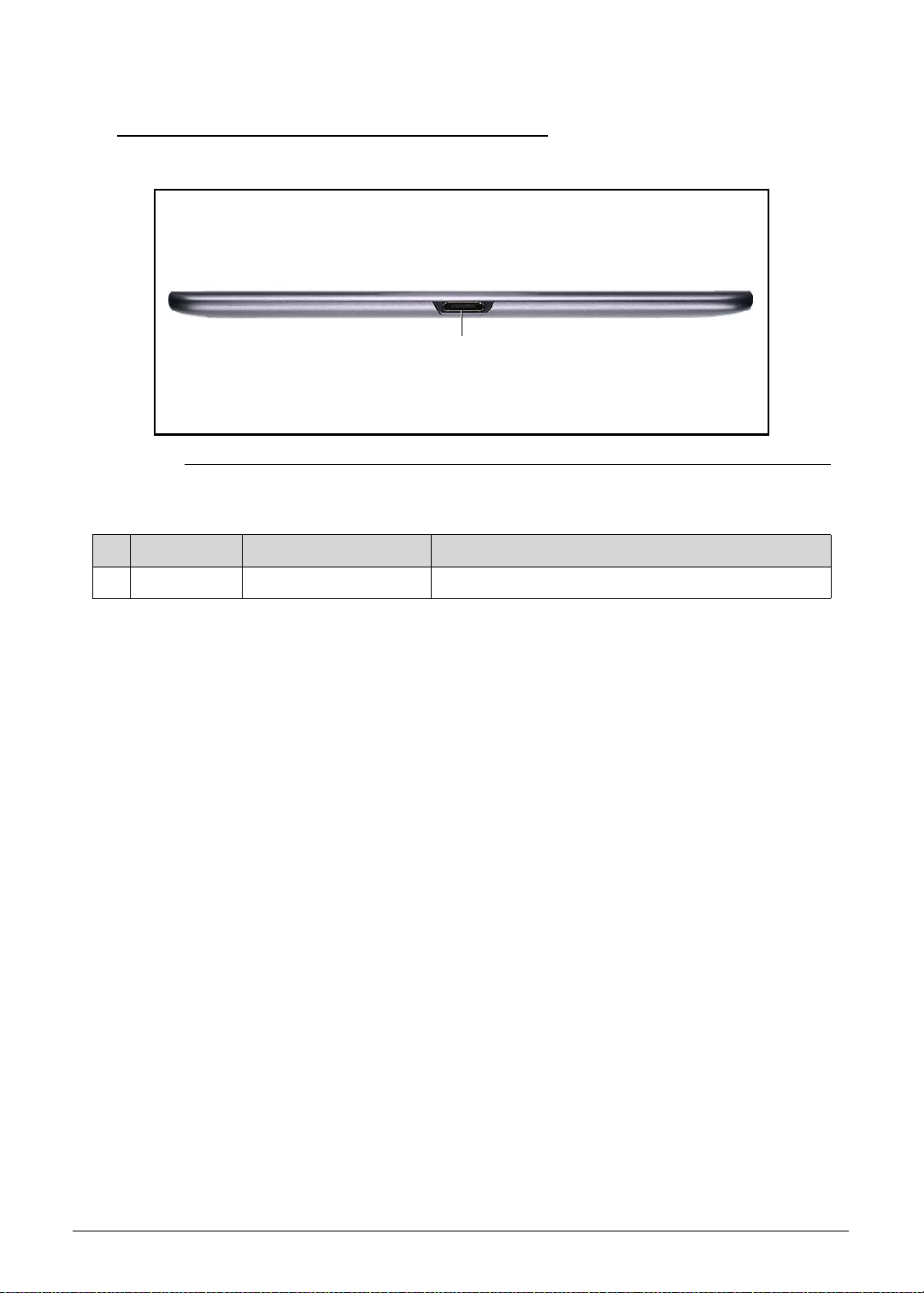
Left View 0
1
Figure 1-4. Left View
Table 1-4. Left View
# Icon Item Description
1 Docking Station Jack
Hardware Specifications and Configurations 1-11
Page 20
Right View 0
Figure 1-5. Right View
Table 1-5. Right View
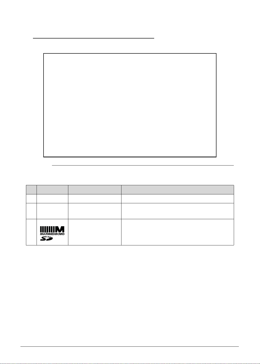
# Icon Item Description
1 Volume Button
2 Touch Screen
Lock Switch
3 Micro-SD &
SIM Card Ports
1-12 Hardware Specifications and Configurations
Page 21
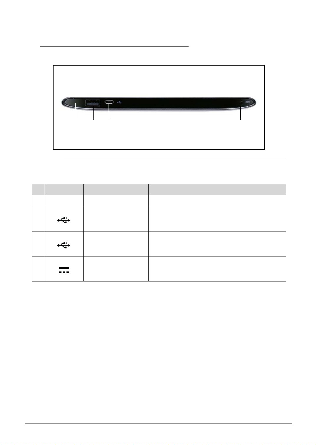
Bottom View 0
2 341
Figure 1-6. Bottom View
Table 1-6. Bottom View
# Icon Item Description
1 Reset Button
2 USB Port
3 Micro-USB Port
4 AC Adapter Jack
Hardware Specifications and Configurations 1-13
Page 22
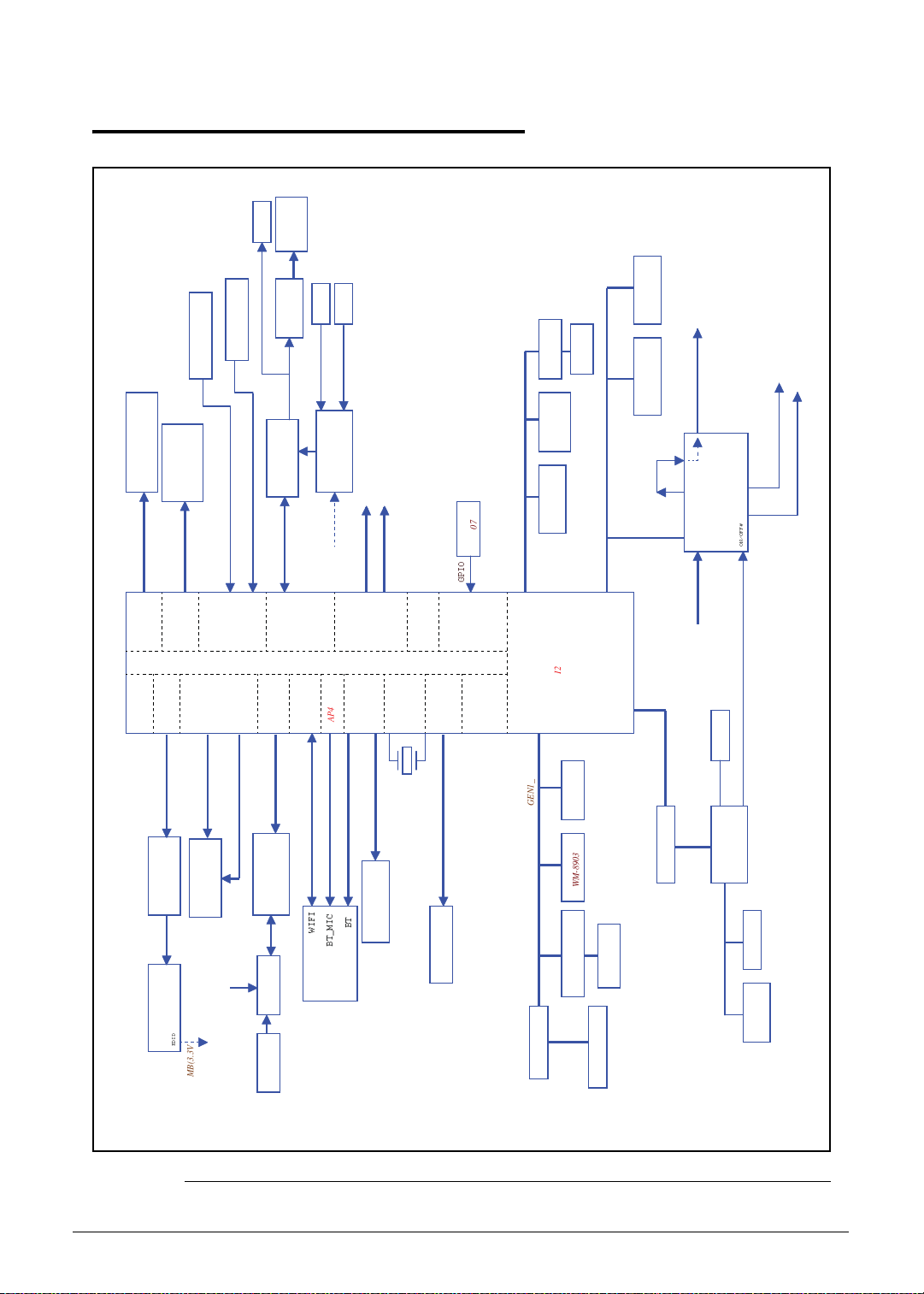
System Block Diagram 0
HeadPhone
INT Speaker
Compass
Temperature
AKM8975C
Sensor NCT-1008
LDO 0 ~ 9 for CPU
Rear MIC
Front MIC
SPKR AMP
ALC105
2M CAMERA Module
5M CAMERA Module
Flash LED
Flash LED
Controller
5M CAMERA
Module
eMMC NAND 4.3 / 4.41
8 bits HSMMC
NAND Ctrl
VGA
FM2018
DAP4(1.8V)
BC4329
Echo & Noise Cancel
EC_SMB
DAP4
UART3 (1.8V)
BT_MIC
WIFI / BT
module
BT
to USB board
USB1
USB +
UART
UART2 (1.8V)
mini-B
to USB board
P-SENSOR
USB3
connector
GPIO
HSIC
Nvidia Tegra T20
SDIO3
OSC,PLL,
12MHz
SDIO3(3.3V)
GPS Module
SDIO Card Slot
CM3607
GPIO
+3.7V_SM2
2M CAMERA
Module
PWR_I2C(1.8V)
CAM_I2C(1.8V)
I2C
core & fuse
GEN2_I2C(1.8V)
GEN1_I2C(1.8V)
AL3000A
Light Sensor
WM-8903
Audio Codec
KXTF9-4100
Accelerometer
GYRO PMU-3050
I2C Level shifter
Touch Screen
CANDO + Atmel
GEN1_I2C(3.3V)
PMU TI TPS658621C
+5V_ALW Input
SPI ROM
SPI
AP_SMB(3.3V)
I2C Level shifter
EC_SMB
512MB / 1GB
LPDDR2 X 1
CSI A (1.2V)
(1.2V,1.8V)
DDR2 32bits
DDR
LCD
HDMI
HDMI
RGB (1.8V)
HDMI Conn.
LVDS bridge
AP_SMB(3.3V)
10.1" LVDS panel
EDID
T20 GEN2 I2C
AP_SMB(3.3V)
CSI B (1.2V)
VI&DSI/CSI
DDC_I2C(5V)
Audio Codec
Wolfson WM8903
DAP1(1.8V)
AUDIO
SDIO1
ULPI
ULPI (1.8V)
SDIO1(1.8V)
ULPI to USB
(SMSC USB3315)
USB2
WIFI
3G card
SIM card
+1V_SM0 for CPU
+1.2V_SM1 for CPU
ON/OFF#
EC_RESMUE
EC KB930
FM2018
2S1P BATT
Figure 1-7. System Block Diagram
1-14 Hardware Specifications and Configurations
Page 23
Specification Tables 0
NOTE
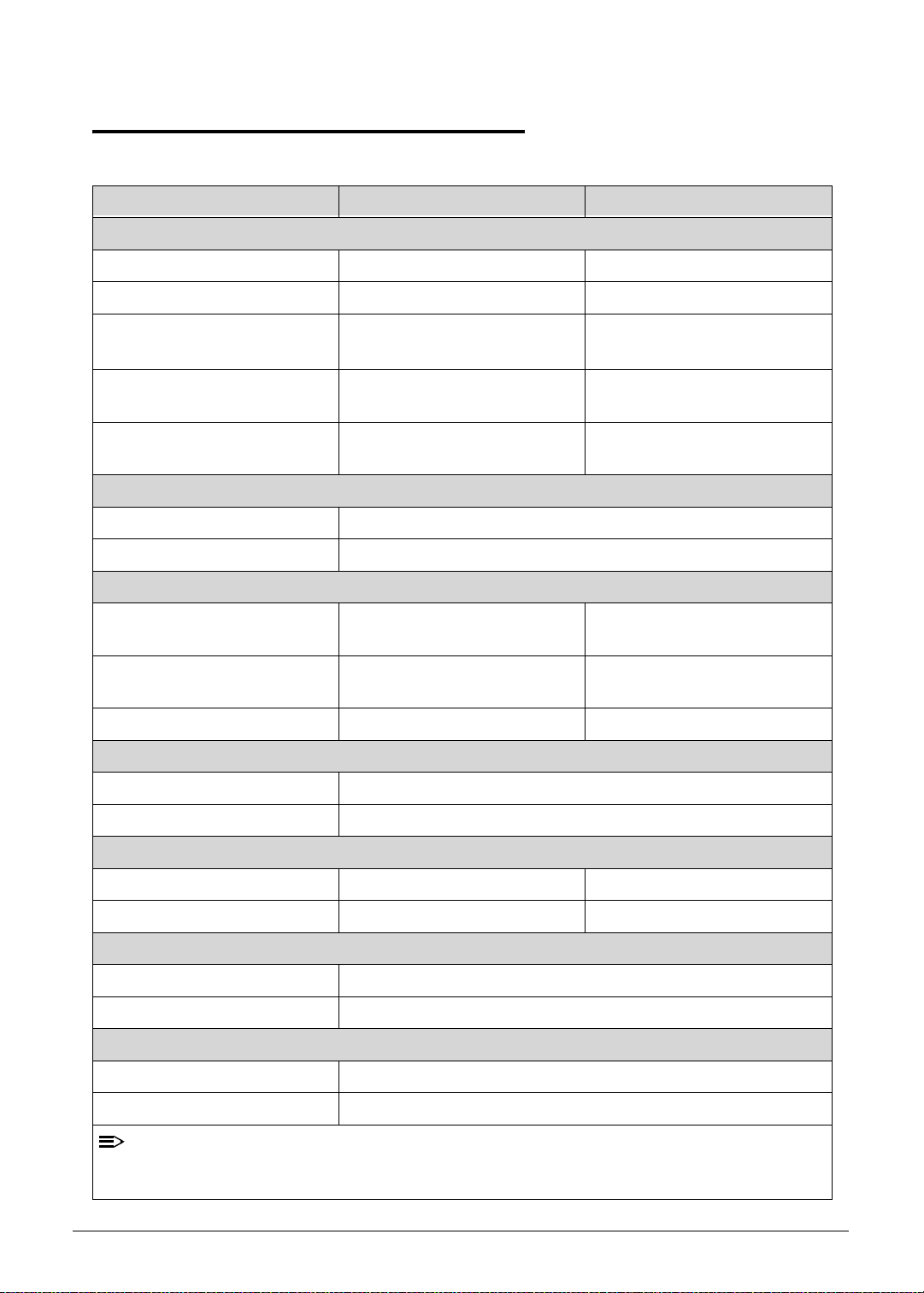
Computer specifications
Item Metric Imperial
Dimensions
Length 260mm 10.23in
Width 177mm 6.96in
Height
(front to rear)
Weight (equipped with optical
drive, flash drive, and battery)
Weight (equipped with optical
drive, flash drive, and battery)
Input power
Operating voltage 12.0 V dc @ 1.5 A - 18 W
Operating current 1.5 A
Temperature
Operating (not writing to
optical disc)
Operating (writing to optical
disc)
Nonoperating -20°C to 60°C -4°F to 140°F
Relative humidity
Operating 10% to 90%
Nonoperating 5% to 95%
13.3mm 0.52in
750g 1.65lb
N/A N/A
0°C to 50°C 32°F to 122°F
0°C to 50°C 32°F to 122°F
Maximum altitude (unpressurized)
Operating -15 m to 3,048 m -50 ft to 10,000 ft
Nonoperating -15 m to 12,192 m -50 ft to 40,000 ft
Shock
Operating 125 g, 2 ms, half-sine
Nonoperating 200 g, 2 ms, half-sine
Random vibration
Operating 0.75 g zero-to-peak, 10 Hz to 500 Hz, 0.25 oct/min sweep rate
Nonoperating 1.50 g zero-to-peak, 10 Hz to 500 Hz, 0.25 oct/min sweep rate
:
Applicable product safety standards specify thermal limits for plastic surfaces. The comp uter
operates well within this range of temperatures.
Hardware Specifications and Configurations 1-15
Page 24
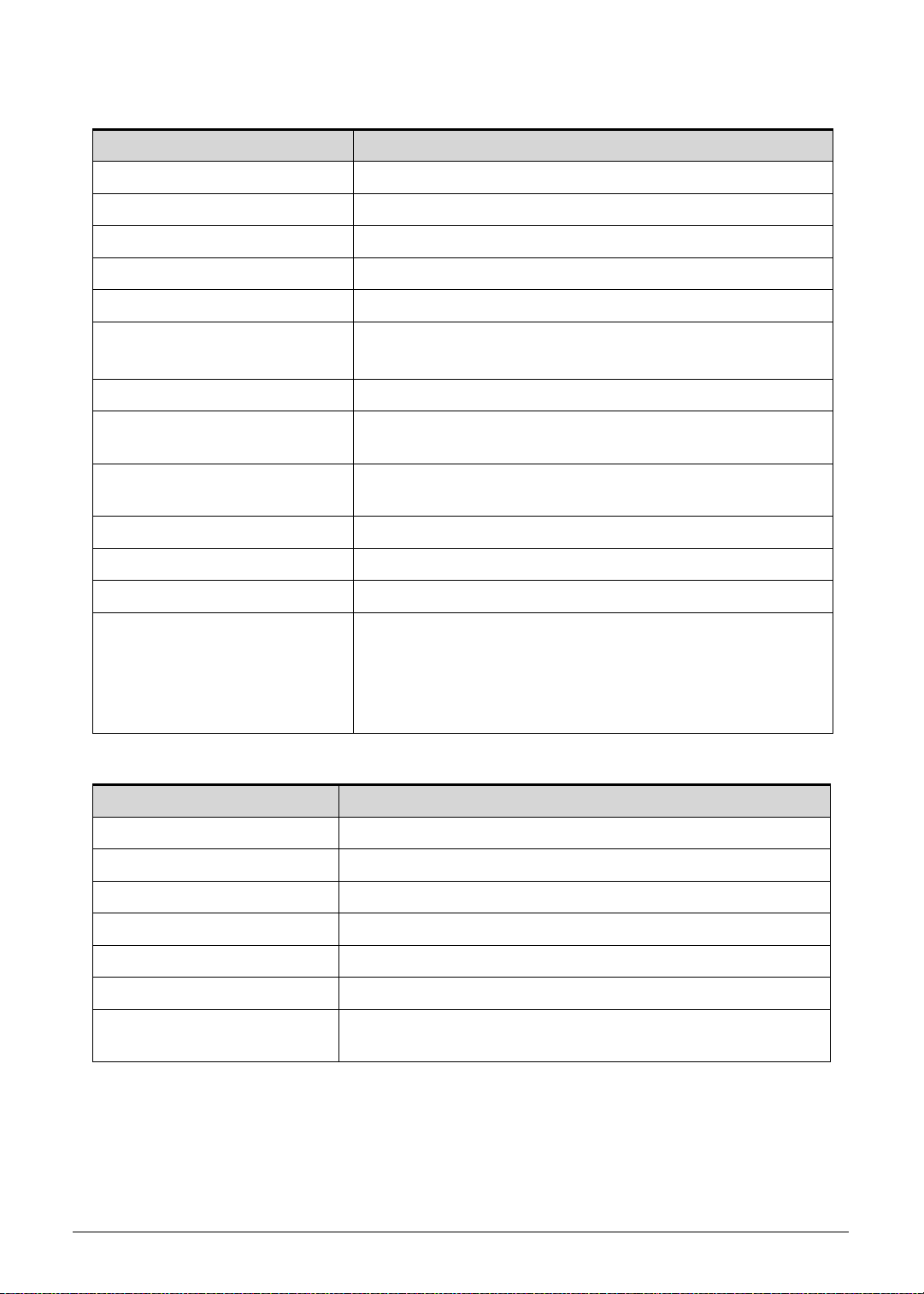
System Board Major Chips
Item Specification
Core logic Tegra 250 Dual cortex A9, 1GHz
VGA Integrate in Tegra 250 CPU
LAN not in this computer
USB 2.0 Integrate in Tegra 250 CPU
Super I/O controller N/A
Bluetooth Broadcom BCM4329
Wireless Broadcom BCM4329
PCMCIA N/A
Audio codec Wolfson WM8903
Card reader SD 2.0 Integrate in Tegra 250 CPU
LVDS transmitter SN75LVDS83B
PMU TI TPS658621C
LDDR2 Elpida EDB8132B2PB 1GB
ULPI Phy for USB SMSC USB3315
GPS Broadcom BCM4751
TOUCH controller Atmel ATMXT 1386-CHIPSET1PJA101
eMMC Hynix H26M32001DAR
CAMERA
Omnivison OV5650: 5M
Various CSI: 2M
Thermal Sensor Onsemi NTC1008
Battery Charger TI BQ24617
Compass Asahi Kasei AKM8975C
Gyro Invensense MPU-3050
ALS/Proximity Lite On AL3000A / AZOTEK IQS128
Processor
Item Specification
CPU type
Dual-core ARM
®
Coretex-A9 MPcore Processor
CPU package 23 x 23 FCBGA
Core Logic Integrate in Tegra 250 CPU
Chipset Integrate in Tegra 250 CPU
1-16 Hardware Specifications and Configurations
Page 25
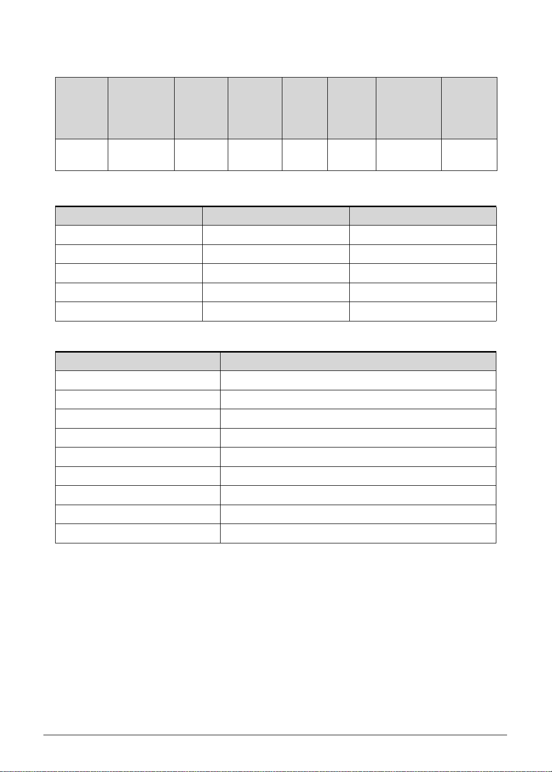
Processor Specifications
Item CPU Speed
(GHz)
Cores/
Threads
Bus
Speed
(FSB/
Mfg
Tech
(nm)
Cache
Size
Package Voltage
DMI/QBI)
T20 1 GHz 2 Cores 40 nm 23x23
FCBGA
CPU Fan True Value Table (N/A)
CPU Temperature Fan Speed (RPM) SPL Spec (dBA)
60
70
80
90
100
System Memory
Item Specification
Memory controller Build in CPU
1.0-1.2V
Memory size 1G LPDDRII
DIMM socket number N/A. On board memory
Supports memory size per socket N/A
Supports maximum memory size On board LP-DDR2 1GB
Supports DIMM type N/A
Supports DIMM Speed N/A
Support DIMM voltage N/A
Supports DIMM package N/A
Hardware Specifications and Configurations 1-17
Page 26
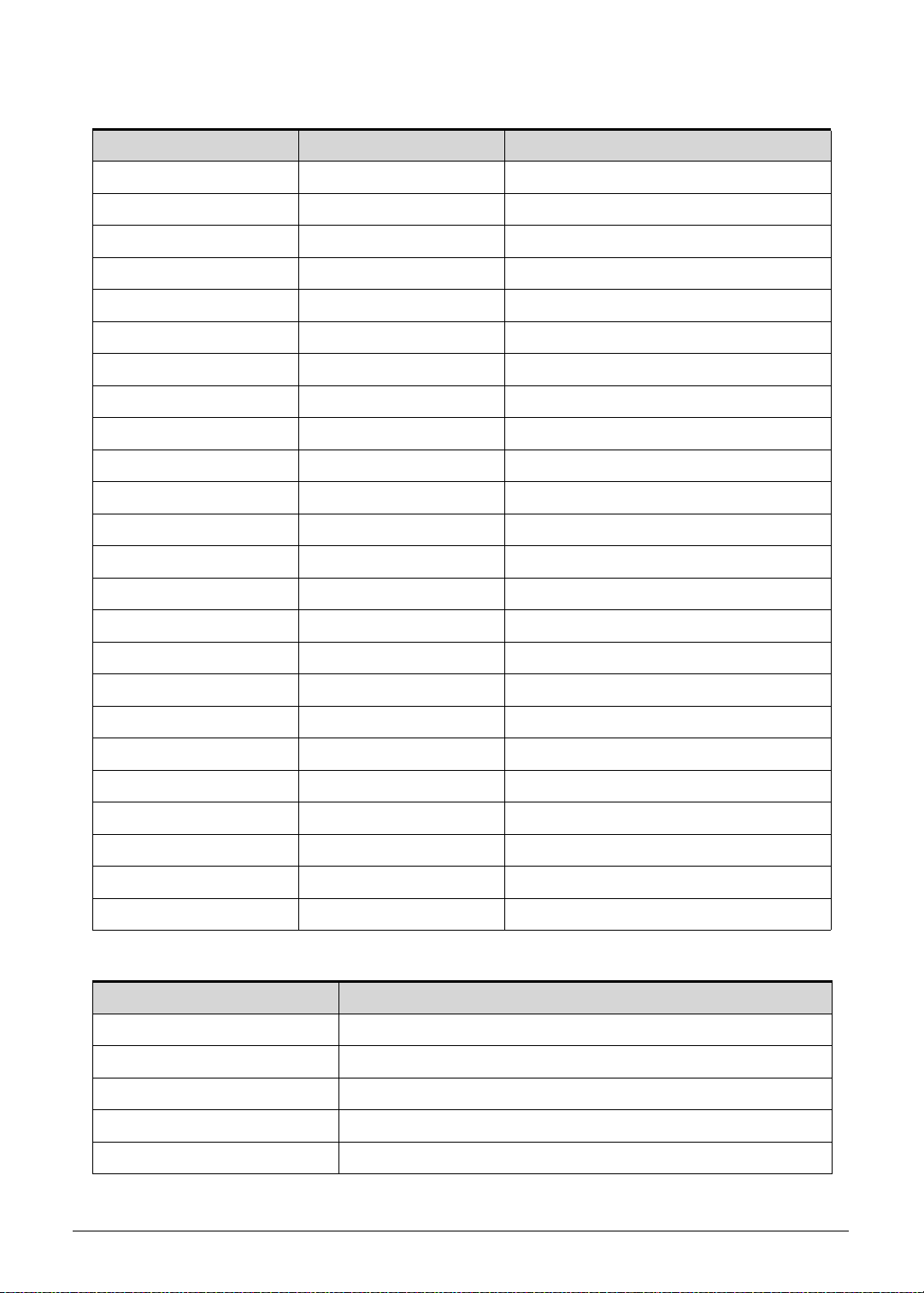
Memory Combinations
Slot 1 (MB) Slot 2 (MB) Total Memory (MB)
0 1024 1024
0 2048 2048
0 4096 4096
0 8192 8192
1024 0 1024
1024 1024 2048
1024 2048 3072
1024 4096 5120
1024 8192 9216
2048 0 2048
2048 1024 3072
2048 2048 4096
2048 4096 6144
2048 8192 10240
4096 0 4096
4096 1024 5120
4096 2048 6144
4096 4096 8192
4096 8192 12288
8192 0 8192
8192 1024 9216
8192 2048 10240
8192 4096 12288
8192 8192 16384
Video Inte rface
Item Specification
Chipset Wolfson WM8903
Package QFN 5X5 40 pin
Interface I2S
Compatibility I2S audio Interface.
Sampling rate 44.1KHz
1-18 Hardware Specifications and Configurations
Page 27
BIOS (N/A)
Item Specification
BIOS vendor
BIOS Version
BIOS ROM type
BIOS ROM size
Features
LAN Interface (N/A)
Item Specification
LAN Chipset
LAN connector type
LAN connector location
Features
Keyboard (N/A)
Item Specification
Type
Total number of keypads
Windows logo key
Internal & external keyboard
work simultaneously
Features
Hardware Specifications and Configurations 1-19
Page 28
Hard Disk Drive (AVL components) (N/A)
NOTE
Item Specification
Vendor & Model
Name
Capacity (GB)
Bytes per sector
Data heads
Drive Format
Disks
Spindle speed
(RPM)
Performance Specifications
Buffer size
Interface
Fast data transfer
rate (Mbits / sec,
max)
Media data transfer
rate
(Mbytes/sec max)
DC Power Requirements
Voltage tolerance
:
1-20 Hardware Specifications and Configurations
Page 29
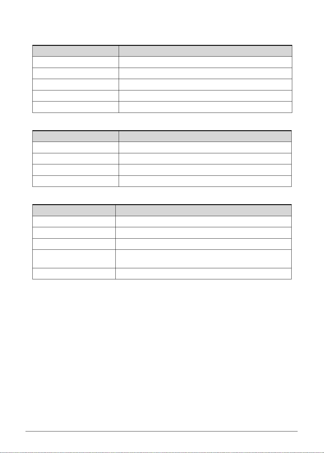
Embedded MultiMediaCard (AVL components)
Item Specification
Vendor & Model
Name
Capacity (GB)
Sandisk
SDIN4C2-16G
Samsung
KLMAG4EEHM
16G 16G 32G 32G
DC Power Requirements
Voltage tolerance 1.8V
Super-Multi Drive (N/A)
Item Specification
Vendor & Model name
Performance Specification
Transfer rate (KB/sec)
Buffer Memory
Interface
Applicable disc format
Loading mechanism
Power Requirement
Input Voltage
Sandisk
SDIN4E2-32G
Samsung
KLMBG8FEJA
BD Drive (N/A)
Items Specifications
Vendor & Model
name
Performance
Specification
Transfer rate
(KB/sec)
Buffer Memory
Interface
Applicable disc
format
Loading mechanism
Power Requirement
Input Voltage
Hardware Specifications and Configurations 1-21
Page 30
LED 10.1”
Item Specification
Vendor/Model name AUO/B101EW05 V1
Screen Diagonal (mm) 255.85 mm
Active Area (mm) 216.96 mm x 135.6 mm
Display resolution (pixels) 1280x 3(RGB) x 800
Pixel Pitch (mm) 0.1695mm × 0.1695mm
Typical White Luminance
2
(cd/m
) also called Brightness
300 cd/m2
Contrast Ratio 1000 min / 1300 type
Response Time (Optical Rise
25 ms / 35 ms
Time/Fall Time) msec
Typical Power Consumption
3.4 W
(watt)
Weight (without inverter) 180 max
Physical Size (mm) 229.46 mm x 149.1mm x 5.2 max
Electrical Interface 1 channel LVDS
Viewing Angle (degree)
85 (Right) / 85 (Left) / 85 (Upper) / 85 (Lower) Typ.
Horizontal (Right) CR = 10
(Left)
Vertical (Upper) CR = 10
(Lower)
LCD Inverter (N/A)
Item Specification
Vendor & Model name
Brightness conditions
Input voltage (v)
Input current (mA)
Output voltage (V, RMS)
Output current (mA, RMS)
Output voltage frequency
(KHz)
1-22 Hardware Specifications and Configurations
Page 31

Display Supported Resolution (LCD)
NOTE
NOTE
Resolution 16 bits 32 bits Intel NVIDIA ATI
1280x 3(RGB) x 800 X X X V X
:
Resolution fixed at 1280 x 800. Not adjustable by end user.
Graphics Controller (N/A)
Item Specification
VGA Chip
Supports
Display Supported Resolution (GPU)
Resolution 16 bits 32 bits Intel NVDIA ATI
1280x 3(RGB) x 800 X X X V X
:
Resolution fixed at 1280 x 800. Not adjustable by end user.
Bluetooth Interface
Item Specifications
Chipset Azurewave AW-NH611- Broadcom 4329 SIP
Data throughput
Protocol
TX 1.2Mbits/sec
RX 1.2Mbits/sec
OPP 1.0 (Object Push Profile)
OBEX 1.1 (Object Exchange Profile)
HSP 1.1 (Headset Profile)
A2DP 1.2 (Advanced Audio Distribution Profile)
AVRCP 1.0 (Audio/Video Remote Control Profile)
GAVDP 1.0 (Generic Audio/Video Distribution Profile)
GAP (Generic Access Profile)
Interface SIP
Connector type SIP
Supported protocol A2DP
Bluetooth Module
Item Specifications
Controller Azurewave AW-NH611 - Broadcom BCM43 29 SoC
Features
Hardware Specifications and Configurations 1-23
Fully support BT 2.1 +EDR
UART Interface
Page 32

Front Camera
Item Specification
Vendor and Model Chicony / Aptina 2031
Type 2M
Rear Camera
Item Specification
Vendor and Model
Liteon / OV5650 CSI
Liteon / Aptina 5140
Type 5M
Mini Card
Item Specification
Number supported 1
Features 1 mini card slot (for WWAN)
3G Card
Item Specification
Features
3G Module with Huawei 770W
3G Module with Huawei 820W
3G Module with Ericsson 5521gw
3G Module with Gobi3000
1-24 Hardware Specifications and Configurations
Page 33

Audio Codec and Amplifier
Item Specification
Audio Controller Audio codec: Wolfson WM8903
Features
4.5mW Power consumption for DAC to headphone playback
DAC SNR 96dB typical , THD -86dB typical
ADC SNR 92dB typical , THD -80dB typical
Control sequencer for pop minimized start-up and shut-down
Single register write for default start-up sequ ence
Stereo digital microphone input
3 single ended inputs per stereo channel
2 pseudo differential inputs per stereo channel
1 fully differential mic inputs per stereo channel
Digital Dynamic Range Controller
Digital sidetone mixing
Ground-referenced headphone driver
Ground-referenced line input
Stereo differential line driver for direct interface to WM9001
40-pin5x5mm QFN package
Amplifier N/A
Features N/A
Audio Interface
speaker driver
Item Specification
Audio Controller Wolfson WM8903
Audio onboard or optional On board
Mono or Stereo Stereo
Resolution Support 24bit
Compatibility I2S audio Interface
Sampling rate Sample rate up to 44.1KHz
Internal microphone Yes
Internal speaker/quantity Yes/(1W speakers x2)
Hardware Specifications and Configurations 1-25
Page 34

Wireless Module 802.11b/g/n
Item Specification
Chipset Azurewave AW-NH611 - Broadcom BCM4329 SoC
Data throughput
802.11b/g: 11~54 Mbps
802.11n: MCS 0-7
Protocol IEEE 802.11b/g/n
Interface SDIO/SPI interface.
Battery
Item Specification
Vendor & Model name SIMPLO BAT-1010 SANYO BAT100
Battery Ty pe Li-ion
Pack capacity 3260mAh/24Wh
Number of battery cell 2
Package configuration 2S1P
VRAM
Item Specification
Chipset T20 UMA architecture
Memory size Share 16 ~ 256MB
Interface LPDDR2
USB Port
Item Specification
USB compliance level USB2.0
Protocol EHCI
Number of USB port(s) 2
Location two at the right side
Output Current 1.5A (for USB host port )
HDMI Port
Item Specification
Compliance level HDMI1.3a
Data throughput Up to 16.7 million colors
Number of HDMI port(s) 1
Location JHDMI1 at the left side
1-26 Hardware Specifications and Configurations
Page 35

AC Adapter
Item Specification
Input rating 18W
Maximum input AC current 0.5A(RMS) at 100Vac
Inrush current 60A Max. @230Vac
Efficiency Refer to EPS 2.0 standard level V
System Power Management
Item Specification
Mech. Off (G3) Only EC working.
Soft Off (G2/S5) Only EC working.
Working (G0/S0) Individual devices such as the CPU and eMMC may be power
managed in this state.
Suspend to RAM (S3)
CPU suspend
Audio Power Down
eMMC Power Down
LCD power off
MIC power off
Save to Disk (S4) N/A
Card Reader
Item Specification
Chipset Embedded in T20 SOC
Package FCBGA -664 23 X 23
Maximum supported size SD: 32G
Features Storage cards with adapter: micro SD™
System LED Indicator
Item Specification
Lock
System state
White color : Flash on booting
White color and amber color off : System off / suspend
Amber color : Battery in charging
HDD access state N/A
Wireless stat e N/A
Power button backlight Same as system state
Battery state Same as system state
Hardware Specifications and Configurations 1-27
Page 36

System DMA Specification
NOTE
Legacy Mode Power Management
DMA0 Not applicable
DMA1 Not applicable
DMA2 Not applicable
DMA3 Not applicable
DMA4 Direct memory access controller
DMA5 Available for ExpressCard
DMA6 Not Assigned
DMA7 Not Assigned
*ExpressCard controller can use DMA 1, 2, or 5.
System Interrupt Specification (N/A)
Hardware IRQ System Function
IRQ0
IRQ1
IRQ2
IRQ3
IRQ5*
IRQ6
IRQ7*
IRQ8
IRQ9*
IRQ10*
IRQ11
IRQ12
IRQ13
IRQ14
IRQ15
*Default configuration; audio possible configurations are IRQ5, IRQ7, IRQ9, IRQ10, or none.
:
ExpressCards may assert IRQ3, IRQ4, IRQ5, IRQ7, IRQ9, IRQ10, IRQ11, or IRQ15. Either
the infrared or the serial port may assert IRQ3 or IRQ4.
1-28 Hardware Specifications and Configurations
Page 37

System IO Address Map (N/A)
I/O address (hex) System Function (shipping configuration)
000 - 00F
010 - 01F
020 - 021
022 - 024
025 - 03F
02E - 02F
040 - 05F
044 - 05F
060
061
062 - 063
064
065 - 06F
070 - 071
072 - 07F
080 - 08F
090 - 091
092
093 - 09F
0A0 - 0A1
I/O Address (hex)
0A2 - 0BF
0C0 - 0DF
0E0 - 0EF
0F0 - 0F1
0F2 - 0FF
100 - 16F
170 - 177
178 - 1EF
1F0 - 1F7
1F8 - 200
201
202 - 21F
Hardware Specifications and Configurations 1-29
Page 38

System I/O Address Specifications (N/A)
I/O address (hex) System Function (shipping configuration)
220 - 22F
230 - 26D
26E - 26
278 - 27F
280 - 2AB
2A0 - 2A7
2A8 - 2E7
2E8 - 2EF
2F0 - 2F7
2F8 - 2FF
300 - 31F
320 - 36F
370 - 377
378 - 37F
380 - 387
388 - 38B
38C - 3AF
3B0 - 3BB
3BC - 3BF
3C0 - 3DF
3E0 - 3E1
3E2 - 3E3
3E8 - 3EF
3F0 - 3F7
3F8 - 3FF
CF8 - CFB
(PCIDIVO-1)
(PCIDIVO-1)
1-30 Hardware Specifications and Configurations
Page 39

CHAPTER 2
System Utilities
Page 40

Introduction . . . . . . . . . . . . . . . . . . . . . . . . . . . . . . . . . . . . . . . . .2-3
2-2
Page 41

System Utilities
Introduction 0
System Utilities 2-3
Page 42

2-4 System Utilities
Page 43

CHAPTER 3
Maintenance Procedures
Page 44

Introduction . . . . . . . . . . . . . . . . . . . . . . . . . . . . . . . . . . . . . . . . .3-3
General Information . . . . . . . . . . . . . . . . . . . . . . . . . . . . . . . . . .3-3
Recommended Equipment . . . . . . . . . . . . . . . . . . . . . . . . . . . . .3-3
Maintenance Flowchart. . . . . . . . . . . . . . . . . . . . . . . . . . . . . . . .3-4
Getting Started . . . . . . . . . . . . . . . . . . . . . . . . . . . . . . . . . . . . . .3-5
SIM/Micro-SD Card Removal . . . . . . . . . . . . . . . . . . . . . . . . . 3-6
SIM/Micro-SD Card Installation . . . . . . . . . . . . . . . . . . . . . . . 3-8
Lower Case Removal . . . . . . . . . . . . . . . . . . . . . . . . . . . . . . . 3-9
Lower Case Installation . . . . . . . . . . . . . . . . . . . . . . . . . . . . . 3-12
DC-In Cable Removal . . . . . . . . . . . . . . . . . . . . . . . . . . . . . . . 3-17
DC-In Cable Installation . . . . . . . . . . . . . . . . . . . . . . . . . . . . . 3-19
Battery Removal. . . . . . . . . . . . . . . . . . . . . . . . . . . . . . . . . . . 3-20
Battery Installation. . . . . . . . . . . . . . . . . . . . . . . . . . . . . . . . . 3-21
3G Module Removal. . . . . . . . . . . . . . . . . . . . . . . . . . . . . . . . 3-22
3G Module Installation . . . . . . . . . . . . . . . . . . . . . . . . . . . . . 3-24
Docking Board Removal. . . . . . . . . . . . . . . . . . . . . . . . . . . . . 3-25
Docking Board Installation . . . . . . . . . . . . . . . . . . . . . . . . . . 3-28
GPS Antenna Removal . . . . . . . . . . . . . . . . . . . . . . . . . . . . . . 3-29
GPS Antenna Installation. . . . . . . . . . . . . . . . . . . . . . . . . . . . 3-30
Mainboard Removal. . . . . . . . . . . . . . . . . . . . . . . . . . . . . . . . 3-31
Mainboard Installation . . . . . . . . . . . . . . . . . . . . . . . . . . . . . 3-33
Rear CCD Removal . . . . . . . . . . . . . . . . . . . . . . . . . . . . . . . . . 3-36
Rear CCD Installation . . . . . . . . . . . . . . . . . . . . . . . . . . . . . . . 3-38
Front CCD Removal . . . . . . . . . . . . . . . . . . . . . . . . . . . . . . . . 3-39
Front CCD Installation . . . . . . . . . . . . . . . . . . . . . . . . . . . . . . 3-39
Two-Piece Microphone Removal. . . . . . . . . . . . . . . . . . . . . . 3-40
Two-Piece Microphone Installation. . . . . . . . . . . . . . . . . . . . 3-41
Speakers Removal. . . . . . . . . . . . . . . . . . . . . . . . . . . . . . . . . . 3-42
Speakers Installation . . . . . . . . . . . . . . . . . . . . . . . . . . . . . . . 3-42
USB Module Removal. . . . . . . . . . . . . . . . . . . . . . . . . . . . . . . 3-43
USB Module Installation . . . . . . . . . . . . . . . . . . . . . . . . . . . . 3-44
LCD Support Plate Removal. . . . . . . . . . . . . . . . . . . . . . . . . . 3-46
LCD Support Plate Installation. . . . . . . . . . . . . . . . . . . . . . . . 3-49
Touch Screen Board Removal . . . . . . . . . . . . . . . . . . . . . . . . 3-50
Touch Screen Board Installation . . . . . . . . . . . . . . . . . . . . . . 3-51
3G Antenna Removal. . . . . . . . . . . . . . . . . . . . . . . . . . . . . . . 3-53
3G Antenna Installation. . . . . . . . . . . . . . . . . . . . . . . . . . . . . 3-53
WLAN Antenna Removal. . . . . . . . . . . . . . . . . . . . . . . . . . . . 3-55
WLAN Antenna Installation. . . . . . . . . . . . . . . . . . . . . . . . . . 3-56
3-2
Page 45

Machine Maintenance Procedures
Introduction 0
This chapter contains general info rmation about the notebook, a list of tools needed to perform
the required maintenance and step by step procedures on how to remove and install
components from the notebook computer.
General Information 0 Recommended Equipment 0
The following tools are required to perform maintenance on the notebook:
Wrist grounding strap and conductive mat
Flat screwdriver
Philips screwdriver
Screw Name Quantity
M2.0x4.0 Ni 14
M2.0x3.0 7
Machine Maintenance Procedures 3-3
Page 46

Maintenance Flowchart 0
The flowchart in Figure 3-1 provides a graphic representation of the module removal and
installation sequences. It provides information on what components need to be removed and
installed during servicing.
Figure 3-1. Maintenance Flow
3-4 Machine Maintenance Procedures
Page 47

Getting Started 0
The flowchart (Figure 3-1) identifies sections illustrating the entire removal and install
sequence. Observe the order of the sequence to avoid damage to any of the hardware
components.
Perform the following prior to performing any maintenance procedures:
1. Place system on a flat work surface.
2. Disconnect AC Adapter and remove all cables from system and peripherals.
3. Make sure system is completely powered down.
4. To make sure system is completely powered down, press and hold power button (A) for 4
seconds. (Figure 3-2)
a. If the device is in powered down mode, allow device to complete boot process
(approx. 10 sec). Then power down normally.
b. If device is in sleep mode, wait for Home Screen to clear. Then power down
normally.
A
Figure 3-2. Device Overview with Power Button
5. Press and hold Power button for 4 seconds to show Tablet Options dialog.
6. Select Power Off to power down device.
7. From Power Off dialog, select OK.
Machine Maintenance Procedures 3-5
Page 48

SIM/Micro-SD Card Removal 0
1. Open SIM/Micro-SD card cover. (Figure 3-3)
Figure 3-3. Opening SIM/Micro-SD Card Cover
2. Remove SIM card from spring locking mechanism. (Figure 3-4)
Figure 3-4. Removing SIM Card
3-6 Machine Maintenance Procedures
Page 49

3. Remove Micro-SD card from spring locking mechanism. (Figure 3-5)
Figure 3-5. Removing Micro-SD Card
4. Secure SIM/Micro-SD card cover. (Figure 3-6)
Figure 3-6. Securing SIM/Micro-SD Card Cover
Machine Maintenance Procedures 3-7
Page 50

SIM/Micro-SD Card Installation 0
1. Open SIM/Micro-SD card cover. (Figure 3-3)
2. Install and secure SIM card. (Figure 3-4)
3. Install and secure Micro-SD card. (Figure 3-5)
4. Close and secure SIM/Micro-SD card cover. (Figure 3-6)
3-8 Machine Maintenance Procedures
Page 51

Lower Case Removal 0
Prerequisite:
SIM/Micro-SD Card Removal
1. Open SIM/Micro-SD card cover (A). (Figure 3-7)
Figure 3-7. Opening SIM/Micro-SD Card Cover
2. Insert plastic pry into slot below Micro-SD card cover as shown in Figure 3-8 to unlock
latch. (Figure 3-8)
Figure 3-8. Unlocking Locking Latches (1 of 5)
Machine Maintenance Procedures 3-9
Page 52

3. Starting from edge as shown in Figure 3-9, unlock locking latches on rear cover from
bezel.
Figure 3-9. Unlocking Locking Latches (2 of 5)
Figure 3-10. Unlocking Locking Latches (3 of 5)
3-10 Machine Maintenance Procedures
Page 53

Figure 3-11. Unlocking Locking Latches (4 of 5)
Figure 3-12. Unlocking Locking Latches (5 of 5)
Machine Maintenance Procedures 3-11
Page 54

4. Remove lower case from bezel. (Figure 3-13)
Figure 3-13. Removing Lower Case
Lower Case Installation 0
1. Open SIM/Micro-SD card cover. (Figure 3-14)
Figure 3-14. Opening SIM/Micro-SD Card Cover
3-12 Machine Maintenance Procedures
Page 55

2. Align Micro-SD port with slot on bezel. (Figure 3-15)
Figure 3-15. Aligning Lower Case with Bezel
3. Install lower case on bezel. (Figure 3-16)
Figure 3-16. Installing Lower Case on Bezel
Machine Maintenance Procedures 3-13
Page 56

4. Starting at volume button, secure locking latches to rear cover on all sides of bezel.
(Figure 3-17 through Figure 3-20)
Figure 3-17. Securing Locking Latches (1 of 4)
Figure 3-18. Securing Locking Latches (2 of 4)
3-14 Machine Maintenance Procedures
Page 57

Figure 3-19. Securing Locking Latches (3 of 4)
Figure 3-20. Securing Locking Latches (4 of 4)
Machine Maintenance Procedures 3-15
Page 58

5. Secure SIM/Micro-SD card cover. (Figure 3-21)
Figure 3-21. Securing SIM/Micro-SD Card Cover
6. Install SIM/Micro-SD card.
3-16 Machine Maintenance Procedures
Page 59

DC-In Cable Removal 0
Prerequisite:
Lower Case Removal
1. Remove tape (A) covering DC-In and antenna cables. (Figure 3-22)
A A
Figure 3-22. Removing Protective Tape
2. Disconnect DC-In cable (B) from mainboard connector (b). (Figure 3-23)
B
b
Figure 3-23. Disconnecting DC-In Cable
Machine Maintenance Procedures 3-17
Page 60

3. Remove DC-In cable from the LCD support plate (C) and bezel (D) guides. (Figure 3-24)
C
D
Figure 3-24. Removing DC-In Cable
4. Remove DC-In jack from bezel. (Figure 3-25)
Figure 3-25. Removing DC-In Jack
3-18 Machine Maintenance Procedures
Page 61

DC-In Cable Installation 0
1. Install and secure DC-In jack on bezel. (Figure 3-25)
2. Connect DC-In cable (B) to mainboard connector (b). (Figure 3-23)
3. Install and secure DC-In cable to bezel (D) and LCD support plate (C) guides.
(Figure 3-24)
4. Install and secure tape (A) covering DC-In and antenna cables. (Figure 3-22)
5. Install lower case.
Machine Maintenance Procedures 3-19
Page 62

Battery Removal 0
Prerequisite:
DC-In Cable Removal
1. Remove four (4) screws (A) from LCD support plate. (Figure 3-26)
A
A
Figure 3-26. Removing Battery Screws
2. Disconnect battery cable (B) from mainboard connector (b). (Figure 3-27)
A
A
B
b
Figure 3-27. Disconnecting Battery Cable
3-20 Machine Maintenance Procedures
Page 63

3. Remove battery (C). (Figure 3-28)
Figure 3-28. Removing Battery
C
Battery Installation 0
1. Install battery (C) on LCD support plate. (Figure 3-28)
2. Connect battery cable (B) to mainboard connector (b). (Figure 3-27)
3. Install and secure four (4) screws (A) to LCD support plate. (Figure 3-26)
4. Install DC-In cable.
ID Size Quantity Screw Ty pe
A M2.0x4.0 Ni 4
Machine Maintenance Procedures 3-21
Page 64

3G Module Removal 0
Prerequisite:
Battery Removal
1. Locate 3G module (A) on LCD support plate. (Figure 3-29)
A
Figure 3-29. 3G Module on LCD Support Plate
2. Disconnect auxiliary (blue) and main (black) cables from 3G module connectors.
(Figure 3-30)
Figure 3-30. Disconnecting 3G Cables
3-22 Machine Maintenance Procedures
Page 65

3. Remove two (2) screws (B) from LCD support plate. (Figure 3-31)
B
Figure 3-31. Removing 3G Module Screws
4. Remove 3G module (C) from mainboard connector (c). (Figure 3-32)
C
c
Figure 3-32. Removing 3G Module
Machine Maintenance Procedures 3-23
Page 66

3G Module Installation 0
1. Install and connect 3G module (C) to mainboard connector (c). (Figure 3-32)
2. Install and secure two (2) screws (B) to LCD support plate. (Figure 3-31)
3. Connect main 3G antenna cable (black) to 3G module connector labeled M. (Figure 3-30)
4. Connect auxiliary 3G antenna cable (blue) to 3G module connector labeled A.
5. Install battery.
ID Size Quantity Screw Ty pe
A M2.0x3.0 2
3-24 Machine Maintenance Procedures
Page 67

Docking Board Removal 0
Prerequisite:
Battery Removal
1. Locate Docking Board (A). (Figure 3-33)
A
Figure 3-33. Docking Board Overview
2. Disconnect docking board FFC (B) from docking board connector (b). (Figure 3-34)
b
B
Figure 3-34. Disconnecting Docking Board FFC from Docking Board
Machine Maintenance Procedures 3-25
Page 68

3. Disconnect docking board FFC (C), labeled MB, fr om mainboard connector (c).
(Figure 3-35)
c
Figure 3-35. Disconnecting Docking Board FFC from Mainboard
4. Remove three (3) screws (C) from bezel. (Figure3-36)
C
D
Figure 3-36. Removing Docking Board Screws
3-26 Machine Maintenance Procedures
Page 69

5. Remove docking board from bezel. (Figure 3-37)
Figure 3-37. Removing Docking Board
Machine Maintenance Procedures 3-27
Page 70

Docking Board Installation 0
1. Align docking board with bezel guides (E). (Figure 3-38)
E
Figure 3-38. Aligning Docking Board Bezel Guides
2. Install board on bezel. (Figure 3-37)
3. Install and secure three (3) screws (D) to bezel. (Figure 3-36)
4. Install and connect docking board FFC (C), labeled MB, to mainboard connector (c).
(Figure 3-35)
5. Install and connect docking board FFC (B) to docking board connector (b). (Figure 3-34)
6. Install battery.
ID Size Quantity Screw Ty pe
B M2.0x3.0 3
3-28 Machine Maintenance Procedures
Page 71

GPS Antenna Removal 0
Prerequisite:
Battery Removal
1. Disconnect GPS antenna (A) from mainboard connector. (Figure 3-39)
A
Figure 3-39. Disconnecting GPS Antenna
2. Remove GPS module. (Figure 3-40)
Figure 3-40. Removing GPS Module
Machine Maintenance Procedures 3-29
Page 72

GPS Antenna Installation 0
1. Install GPS module on bezel. (Figure 3-40)
2. Connect GPS antenna (A) to mainboard connector. (Figure 3-39)
3. Install battery.
3-30 Machine Maintenance Procedures
Page 73

Mainboard Removal 0
Prerequisite:
3G Module Removal
1. Disconnect the following cables: (Figure 3-41)
Front and rear microphone cables (A) from mainboard connectors (a)
Touch screen cable (B) from mainboard connector (b)
Main (black) WLAN cable (C) from mainboard connector (c)
Front camera FFC (D) from mainboar d conn e cto r (d )
LVDS cable (E) from mainboard connector (e)
Speaker cable (F) from mainboard connector (f)
USB FFC (G) from mainboard connector (g)
F
g
G
f
e
d
b
E
a
D
C
B
A
Figure 3-41. Disconnecting Cables from Mainboard
Machine Maintenance Procedures 3-31
Page 74

2. Remove screw (H) and four (4) screws (J) from bezel. (Figure 3-42)
H
Figure 3-42. Removing Mainboard Screws
3. Lift and remove mainboard from bezel. (Figure 3-43)
J
Figure 3-43. Removing Mainboard
3-32 Machine Maintenance Procedures
Page 75

Mainboard Installation 0
!
CAUTION:
The touch screen lock button guides may be damaged when the mainboard
screws are secured. Make sure to align the touch screen lock button switch with
the lock button guides.
1. Set touch screen lock button (K) to unlock position. (Figure 3-44)
K
unlocked locked
Figure 3-44. Setting Touch Screen Lock Button
2. Install mainboard on bezel. (Figure 3-45)
Figure 3-45. Install Mainboard
Machine Maintenance Procedures 3-33
Page 76

3. Align with bezel guide pins (L). (Figure 3-46)
L
Figure 3-46. Aligning Mainboard with Bezel Guide Pins
4. Align touch screen lock button switch (M) with lock button guides (N). (Figure 3-47)
M
N
Figure 3-47. Install Mainboard to IO Ports
N
3-34 Machine Maintenance Procedures
Page 77

5. Install and secure one screw (H) and four (4) screws (J) to bezel. (Figure 3-42)
6. Connect the following cables: (Figure 3-41)
Front and rear microphone cables (A) to mainboard connectors (a)
Touch screen cable (B) to mainboard connector (b)
Main (black) WLAN cable (C) to mainboard connector (c)
Front camera FFC (D) to mainboard connector (d)
LVDS cable (E) to mainboard connector (e)
Speaker cable (F) to mainboard connector (f)
USB FFC (G) to mainboard connector (g)
7. Install 3G module (3G SKU)/Battery (Non-3G SKU)
ID Size Quantity Screw Ty pe
H M2.0x3.0 1
J M2.0x4.0 Ni 4
Machine Maintenance Procedures 3-35
Page 78

Rear CCD Removal 0
Prerequisite:
Mainboard Removal
1. Place bottom of mainboard on a flat surface.(Figu re 3-48)
A
Figure 3-48. Mainboard Overview
2. Remove rear camera (A) from mainboard.
3. Remove rear camera holder from mainboard by pressing holder throu gh the board.
(Figure 3-49 through Figure 3-51)
Figure 3-49. Removing Rear CCD Holder (1 of 3)
3-36 Machine Maintenance Procedures
Page 79

Figure 3-50. Removing Rear CCD Holder (2 of 3)
Figure 3-51. Removing Rear CCD Holder (3 of 3)
Machine Maintenance Procedures 3-37
Page 80

Rear CCD Installation 0
1. Align rear camera holder guide (B) with mainboard slot (C).(Figure 3-52)
C
B
Figure 3-52. Align Rear CCD Holder Guide with Mainboard Slot
2. Install and secure rear camera holder on mainboard b y pressing holder into the opening in
the mainboard.(Figure 3-50 through Figure 3-49)
3. Install rear camera (A) on mainboard.(Figure 3-48)
4. Install mainboard.
3-38 Machine Maintenance Procedures
Page 81

Front CCD Removal 0
Prerequisite:
Mainboard Removal
1. Release bezel locking latches (A).(Figure 3-53)
A
A
Figure 3-53. Release Bezel Locking Latches
2. Remove front camera from bezel.(Figure 3-54)
Figure 3-54. Removing Front CCD
Front CCD Installation 0
1. Install and secure front camera in bezel locking latches (A).(Figure 3-53)
2. Install mainboard.
Machine Maintenance Procedures 3-39
Page 82

Two-Piece Microphone Removal 0
Prerequisite:
Mainboard Removal
1. Remove two-piece microphone (A) from bezel guides.(Figure 3-55)
A
Figure 3-55. Removing Two-piece Microphone
3-40 Machine Maintenance Procedures
Page 83

Two-Piece Microphone Installation 0
1. Install and secure microphone (B) in front microphone guide (closest to touch screen
board) facing down.(Figure 3-56)
B
Figure 3-56. Installing Two-piece Microphone to Front Guide
2. Install and secure microphone (C) in rear microphone guide (furthest away from touch
screen board) facing up.(Figure 3-57)
C
Figure 3-57. Installing Two-piece Microphone to Rear Guide
3. Install mainboard.
Machine Maintenance Procedures 3-41
Page 84

Speakers Removal 0
Prerequisite:
Mainboard Removal
1. Remove three (3) screws (A) from bezel.(Figure 3-58)
B
Figure 3-58. LCD Support Plate Overview with Speakers
2. Remove speakers (B) and speaker cable (C) from bezel.
A
C
A
B
Speakers Installation 0
1. Install speakers (B) and speaker cable (C) on bezel. (Figure 3-58)
2. Install and secure three (3) screws (A) to beze l.
3. Install mainboard.
ID Size Quantity Screw Ty pe
A M2.0x4.0 Ni 3
3-42 Machine Maintenance Procedures
Page 85

USB Module Removal 0
Prerequisite:
Speakers Removal
1. Disconnect module FFC (A) from module connector (a). (Figure 3-59)
A
a
Figure 3-59. Disconnecting USB FFC
2. Remove module FFC.
3. Remove two (2) screws (A) from bezel. (Figure 3-60)
B
A
Figure 3-60. Removing USB Module Screws
Machine Maintenance Procedures 3-43
Page 86

4. Remove module support bracket (B).
5. Remove module (C). (Figure 3-61)
Figure 3-61. Removing USB Module
C
USB Module Installation 0
1. Align module with bezel guides (B). (Figure 3-62)
B
Figure 3-62. Aligning USB Module to Bezel Guides
2. Install module on bezel.
3. Install module support bracket (B) on bezel. (Figure 3-60)
4. Install and secure two (2) screws (A) to bezel.
5. Install and connect module FFC (C) to module connector (c). (Figure 3-59)
6. Install speakers.
3-44 Machine Maintenance Procedures
Page 87

ID Size Quantity Screw Ty pe
A M2.0x4.0 Ni 2
Machine Maintenance Procedures 3-45
Page 88

LCD Support Plate Removal 0
Prerequisite:
Speakers Removal
1. Remove Mylar tape (A) from LCD support plate. (Figure 3-63)
A
A
Figure 3-63. Removing Mylar Tape
2. Remove antenna cables from LCD support plate guides (B). (Figure3-64)
B
B
Figure 3-64. Removing Antenna Cables
3-46 Machine Maintenance Procedures
Page 89

3. Remove one screw (C) and one screw D) from bezel. (Figure 3-65)
C
Figure 3-65. Removing LCD Support Plate Screws
4. Remove LCD support plate. (Figure 3-66)
D
Figure 3-66. Removing LCD Support Plate
5. Disconnect touch screen FFC (E) from board connector (e). (Figure 3-67)
Machine Maintenance Procedures 3-47
Page 90

e
E
Figure 3-67. Disconnecting Touch Screen FFC
6. Remove adhesive tape (F) covering LVDS cable (G) and LCD panel connector (g).
(Figure 3-68)
g
G
Figure 3-68. Removing LVDS Adhesive Tape
7. Disconnect and remove LVDS cable.
F
3-48 Machine Maintenance Procedures
Page 91

LCD Support Plate Installation 0
1. Connect LVDS cable (G) to LCD panel connector (g). (Figure 3-68)
2. Install and secure adhesive tap e (F) covering LVDS cable and LCD panel connector.
3. Connect and secure touch screen FFC (F) to board connector (f). (Figure 3-67)
4. Install LCD support plate on bezel. (Figure 3-66)
5. Install and secure one screw (C) and one screw (D) to bezel. (Figure 3-65)
6. Install and secure antenna cables to LCD supp ort plate guides (B). (Figure 3-64)
7. Install and secure Mylar tape (A) to LCD support plate. (Figure 3-63)
8. Install speakers.
ID Size Quantity Screw Ty pe
C M2.0x3.0 1
D M2.0x4.0 Ni 1
Machine Maintenance Procedures 3-49
Page 92

Touch Screen Board Removal 0
Prerequisite:
LCD Support Plate Removal
1. Remove touch screen board (A) from LCD support plate (B). (Figure 3-69 and
Figure 3-70)
B
A
Figure 3-69. Removing Touch Screen Board (1 of 2)
Figure 3-70. Removing Touch Screen Board (2 of 2)
3-50 Machine Maintenance Procedures
Page 93

2. Disconnect and remove touch screen board cable (C) from board connector (c).
(Figure 3-71)
c
C
Figure 3-71. Removing Touch Screen Board Cable
Touch Screen Board Installation 0
1. Install and connect touch screen cable (C) to board connector (c). (Figure 3-71)
2. Align touch screen board to LCD support plate guides (D). (Figure 3-72)
D
Figure 3-72. Aligning Touch Screen Board to LCD Support Plate Guides
3. Install and secure touch screen board on LCD support plate. (Figure 3-73)
Machine Maintenance Procedures 3-51
Page 94

Figure 3-73. Installing Touch Screen Board
4. Install LCD support plate.
3-52 Machine Maintenance Procedures
Page 95

3G Antenna Removal 0
Prerequisite:
LCD Support Plate Removal
1. Remove main (A, black) and auxiliary (B, blue) antennas from bezel. (Figure 3-74)
A
Figure 3-74. Removing 3G Antennas
B
3G Antenna Installation 0
1. Align main (black) antenna to bezel guide (C).(Figure 3-75)
Machine Maintenance Procedures 3-53
Page 96

C
Figure 3-75. Aligning Main 3G Antenna
2. Align auxiliary (blue) antenna to bezel guide (D).(Figure 3-76)
D
Figure 3-76. Aligning Auxiliary 3G Antenna
3. Install and secure 3G antennas on bezel.
4. Install LCD support plate.
3-54 Machine Maintenance Procedures
Page 97

WLAN Antenna Removal 0
Prerequisite:
LCD Support Plate Removal
1. Remove main (black) WLAN antenna (A) from bezel. (Figure 3-77)
A
Figure 3-77. Removing WLAN Antenna
Machine Maintenance Procedures 3-55
Page 98

WLAN Antenna Installation 0
1. Align main (black) WLAN antenna to bezel guide (B).(Figure 3-78)
B
Figure 3-78. Aligning WLAN Antenna
2. Install and secure WLAN antenna on bezel.
3. Install LCD support plate.
3-56 Machine Maintenance Procedures
Page 99

CHAPTER 4
Troubleshooting
Page 100

Introduction . . . . . . . . . . . . . . . . . . . . . . . . . . . . . . . . . . . . . . . . .4-3
General Information . . . . . . . . . . . . . . . . . . . . . . . . . . . . . . . . . .4-3
Power On Issues . . . . . . . . . . . . . . . . . . . . . . . . . . . . . . . . . . . 4-4
No Display Issues. . . . . . . . . . . . . . . . . . . . . . . . . . . . . . . . . . . 4-5
LCD Picture Failure. . . . . . . . . . . . . . . . . . . . . . . . . . . . . . . . . 4-6
Touch Screen Failure . . . . . . . . . . . . . . . . . . . . . . . . . . . . . . . 4-7
Internal Speaker Failure. . . . . . . . . . . . . . . . . . . . . . . . . . . . . 4-8
Internal Microphone Failure . . . . . . . . . . . . . . . . . . . . . . . . . 4-9
USB Failure . . . . . . . . . . . . . . . . . . . . . . . . . . . . . . . . . . . . . . . 4-10
Front Camera Failure . . . . . . . . . . . . . . . . . . . . . . . . . . . . . . . 4-11
Back Camera Failure. . . . . . . . . . . . . . . . . . . . . . . . . . . . . . . . 4-12
P-Sensor Failure . . . . . . . . . . . . . . . . . . . . . . . . . . . . . . . . . . . 4-13
3G Function Failure . . . . . . . . . . . . . . . . . . . . . . . . . . . . . . . . 4-14
Wireless Function Test Failure. . . . . . . . . . . . . . . . . . . . . . . . 4-15
GPS Function Test Failure (Wi-Fi SKU). . . . . . . . . . . . . . . . . . 4-16
GPS Function Test Failure (3G SKU). . . . . . . . . . . . . . . . . . . . 4-17
Docking Station Test Failure . . . . . . . . . . . . . . . . . . . . . . . . . 4-18
Other Functions Failure . . . . . . . . . . . . . . . . . . . . . . . . . . . . . 4-19
4-2
 Loading...