


APRILIA TAB A1-713HD
SERVICE GUIDE
1

Table of Contents
Chapter 1 Product Features and Hardware Specifications
Features………………………………………………….…………………………..……....…1-2
Tablet Tour…………………………………………………………………………….……......…3
Front View………………………………………………………………………….…...4
Rear View………………………………………………………………………….……5
Top View………………………………………………………………………….….….6
Bottom View………………………………………………………………………...….7
Left View……………………………………………………………………….……..…8
Right View……………………………………………………………………...…...….9
System Block Diagram……………………………………………………………………..…..10
Chapter 2 Diagnostic Utilities
Introduction…………………………………………………………………………………….…11
Software Upgrade Tool SOP…………………………………………………………….....11-25
WriteStation Tool SOP……………………………………………………………………....26-58
Re-write Country Code Tool & SOP……………………………………………………...……58
Chapter 3 Service and Maintenance
Introduction……………………………………………………………………………….…..….59
Recommended Equipment……………………………………………………………….........59
Maintenance Flowchart………………………………………………………………….….60-78
Chapter 4 Diagnostic Tool SOP
Index…………………………………………………………………………………………..….80
Introduction and Installation Method…………………………………………...……..…..81-82
Test Items and Function Description…………………………………………..……….....83-84
Operational Methods of Test Items……………………………………………………………85
Test Content Description……………………………………………………………........86-105
Chapter 5 Serial Number Definition
Introduction of Acer FG SN…………………………………………………………...…106-113
Introduction of Acer KC PN and Acer KC SN……………………………………….....114-115
Chapter 6 FRU (Field Replaceable Unit) List
Exploded Diagram………………………………………………………………..………117-119
FRU List………………………………………………………………………………..….120-123
i

Date
Chapter
Update
Revision History
Please refer to the table below for the updates made on this service guide.
Copyright
Copyright 2014 by Acer Incorporated. All rights reserved. No part of this publication may be
reproduced, transmitted, transcribed, stored in a retrieval system, or translated into any
language or computer language, in any form or by any means, electronic, mechanical, magnetic,
optical, chemical, manual or otherwise, without the prior written permission of Acer
Incorporated.
Disclaimer
The information in this guide is subject to change without notice.
Acer Incorporated makes no representatives or warranties, either expressed or implied,
with respect to the contents hereof and specifically any warranties of merchantability or fitness
for any particular purpose. Any Acer Incorporated software described in this manual is sold or
licensed ―as is‖. Should the program prove defective following their purchase, the buyer (and
not Acer Incorporated, its distributor, or its dealer) assumes the entire cost of all necessary
servicing, repair, and any incidental or consequential damages resulting from any defect in the
software.
Acer is a registered trademark of Acer Corporation.
Other brand and product names are trademarks and/or registered trademarks of their
respective holders.
ii

General Information
This Service Guide provides you with all technical information relating to the basic
configuration for Acer’s global product offering. To better fit local market requirement and
enhance product competitiveness, your regional office may have decided to extend the
functionality of a machine (e.g. add-on card, modem, or extra memory capabilities). These
localized features are not covered in this generic service guide. In such cases, contact your
regional offices or the responsible personnel/channel to provide you with further technical
details.
When ordering FRU parts:
Check the most up-to-date information available on your regional web or channel. If, for
whatever reason, a part number change is made, it may not be noted in this printed service
guide.
For Acer-authorized service providers:
Your Acer office may have a different part number code than those given in the FRU list of
this printed service guide. The list provided by your regional Acer office must be used to order
FRU parts for repair and service of customer machines.
iii

CHAPTER 1
Product Features and Hardware Specifications
Product Features and Hardware Specifications
Features………………………………………………….……………………..……….………1-2
Tablet Tour…………………………………………………………………………………..…….3
Front View………………………………………………………………………..….....4
Rear View………………………………………………………………………………5
Top View…………………………………………………………………………….….6
Bottom View………………………………………………………………………...….7
Left View……………………………………………………………………………..…8
Right View………………………………………………………………………..…….9
System Block Diagram………………………………………………………………….……...10

Product Features and Hardware Specifications
Features
The following is a summary of the tablet’s many features:
Selling point
·6.95" WSVGA(600*1024) 3G Android Phone Pad
·Quad Core 1.3GHz
·8GB+1GB
·Android 4.2
·FM/Bluetooth/WiFi AP/GPS
ID type
·Touch
Dimension
·193*116*9.0mm
Target Market
·Global
LCD
·Display 6.95'' WSVGA; compatible 7.0’' WXGA
·Touch panel GFM; GT967, and GT9271 for IPS GFF
·Resolution 600*1024; Color: 262k
Camera
·Main Camera 200W FF; compatible 500W AF
·Front Camera 30W
1

Mechanics
·Battery 3400MAH
·Speaker 1609
·Vibrator compatible
·Side key 3(1power on/off,2 vol+/-)
·3.5mm earphone support
·Keypad blacklight: not support
Hardware
·Platform MT8382W Quad Core 1.3GHz
·Band GSM 850/900/1800/1900,WCDMA 900/2100
·Memory Emmc 8GB+DDR3L 1GB(Emmc 16gb compatible)
·Support MP3/MP4/SD Card(T-Flash up to 32G)/Hands
Interface
·SIM Card slot 1
·Earphone Φ3.5 earphone jack ;CTIA standard, OMTP compatible
·Charger Micro USB 5pin
·USB Micro USB 5pin
·Data download Micro USB 5pin
free/G-SENSOR/Signal/WIFI/BT4.0/GPS/OTG
Accessories
·Charger/USB cable/Battery
2
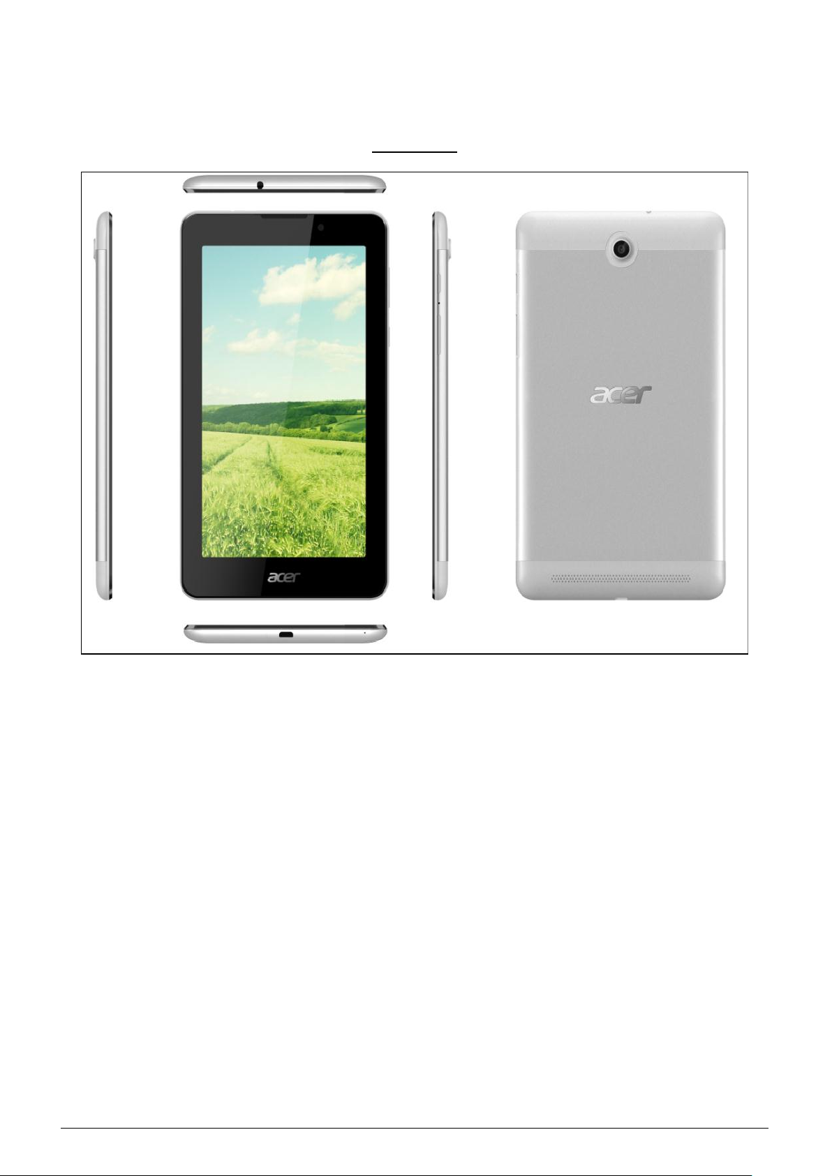
Tablet Tour
Six View
3

#
Item
Description
1
Touch Screen
CTP
2
Receiver
Receiver
3
Front camera
Front camera
1 2 3
Front View
Figure 1.1 Front View
4
#
Item
Description
1
SIM card cover
SIM card cover
2
Rear Camera
Rear Camera
3
Speakers
Emits stereo audio.
2 3 1
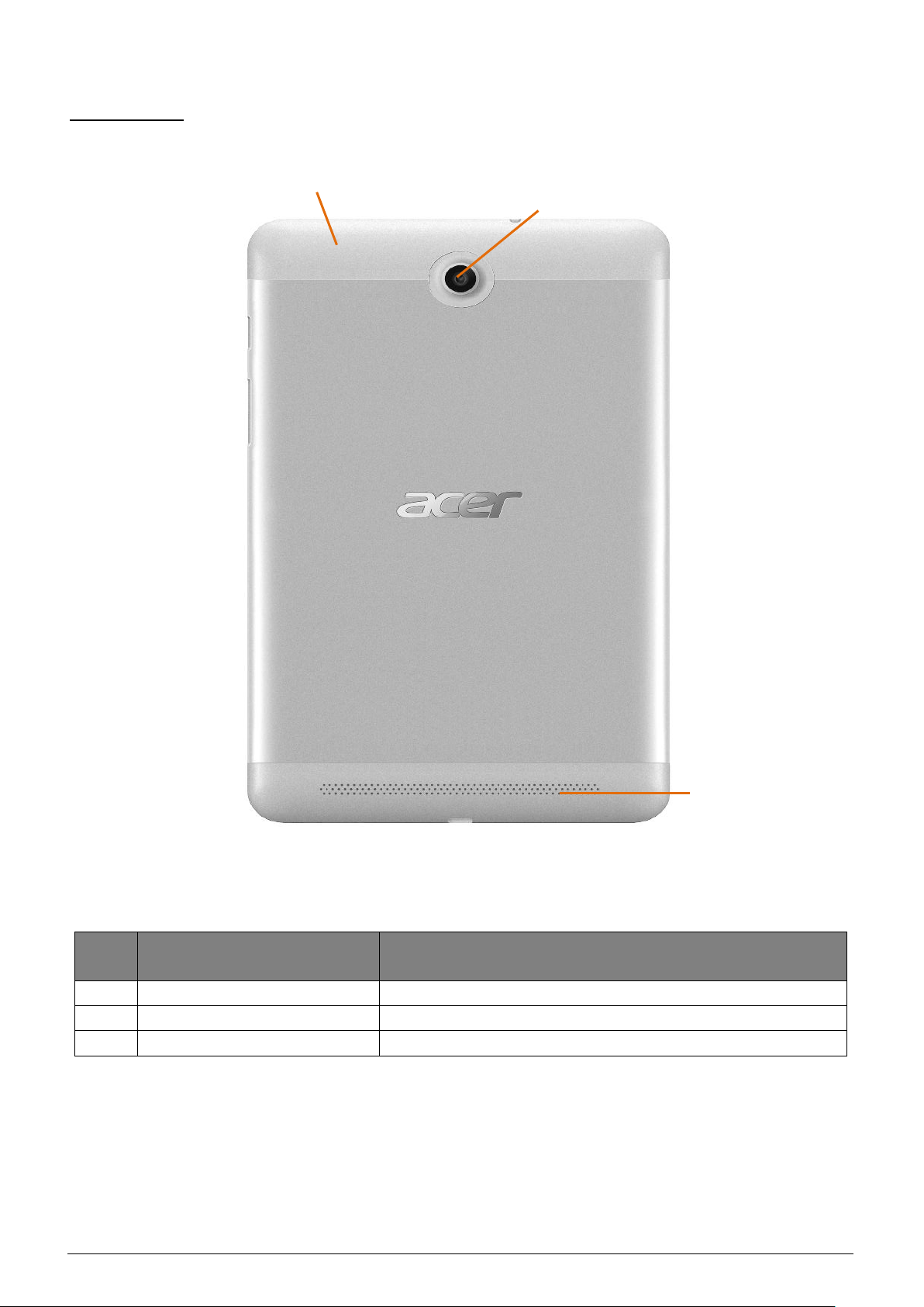
Rear View
Figure 1.2 Rear View
5
#
Icon
Item
Description
1 Headset Jack
Connects to stereo headphones.
1
Top View
Figure 1.3 Top View
6
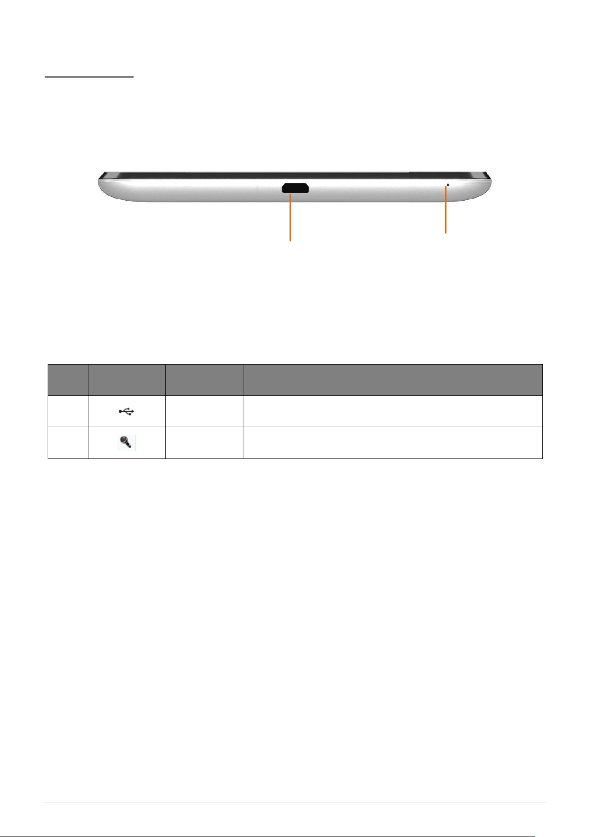
#
Icon
Item
Description
1 USB Port
Connects to a computer with a USB cable.
2 Microphone
Receives audio input.
1
2
Bottom View
Figure 1.4 Bottom View
7

Left View
Figure 1.5 Left View
8
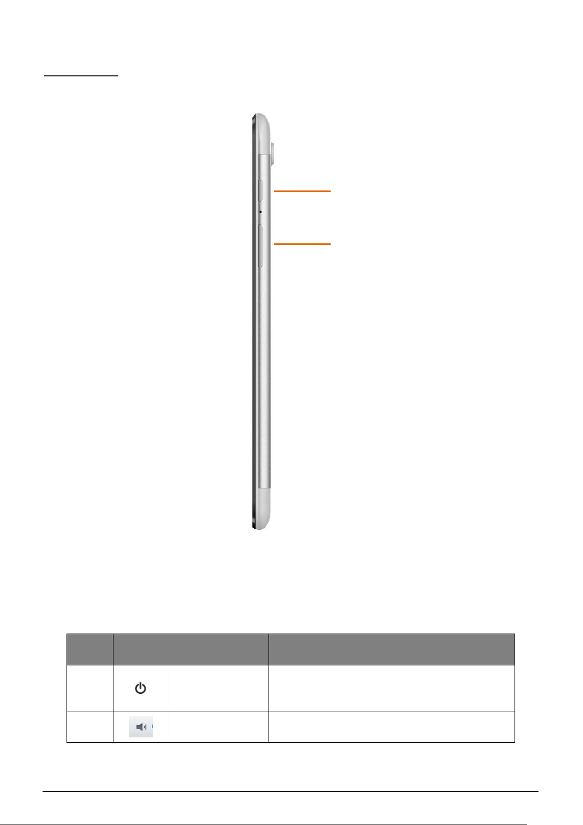
#
Icon
Item
Description
1 Power Button
• Press and hold to turn the tablet on or off.
• Press briefly to turn the screen on/off or enter
sleep mode.
2
Volume +/- Control
Increases or decreases the tablet volume.
1
2
Right View
9
Figure 1.6 Right View
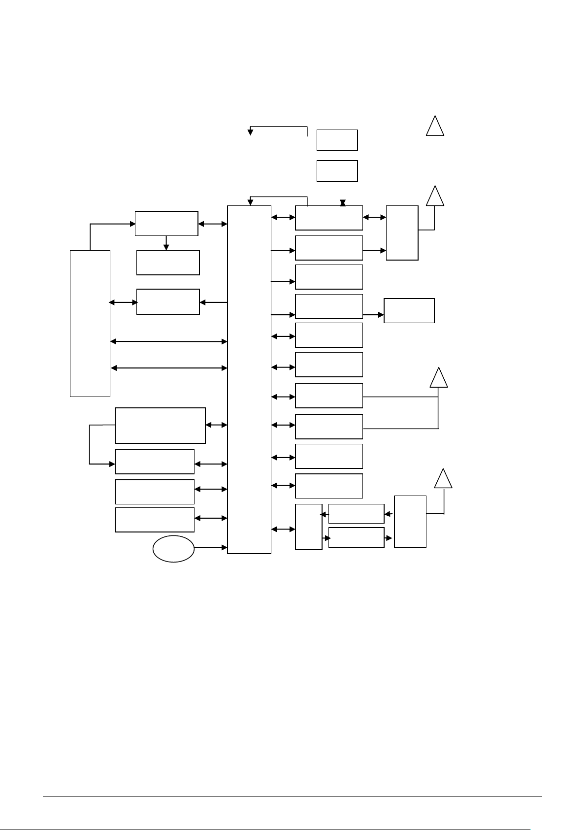
26M
RF_Switc
MT8382
Charger IC
Battery
5PIN USB
3.5MM Earphoen
Jack
FM Radio
Camera
Speaker
WVGA LCD
SIM 1/SIM
Receiver
GPS IC
Bluetooth
ROM+RA
T-FLASH
Audio_PA
RF_Switch
RF-PA
RF-TR
Side Health
RX Filter
WIFI IC
TX PA
MI
26M
OTG
System Block Diagram
26M
5V IN
USB DM/DP
URAT TX/RX
ANT
Remark:FM/GPS/WIFI/BT to Four in Chip
10

CHAPTER 2
Diagnostic Utilities
Introduction
The APRILIA TAB has a software tool designed to software upgrading and a writing tool
designed to write SN/IMEI/BT/WIFI. When using the writing tool, the use needs to install HQ
Framework.
Software Upgrade Tool SOP
Preparation
1) Acer Aprilia Tablet
2) USB Cable: Micro USB 5pin
3) USB Driver: ―Huaqin Android Driver All-in-One 32(or 64) bit
V1.00.exe‖
4) Upgrade Tool: ―hq_mtk_customerdownload_v2.2_131028‖
5) Software
11
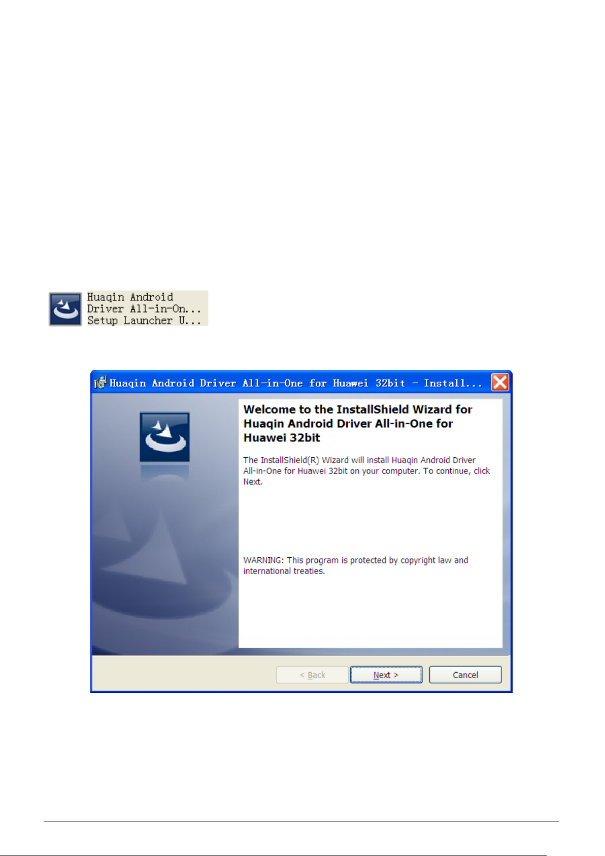
1. Smart Phone Driver Installation
NOTE:
Usually, you should upgrade your target via USB communication mode, so 32 bit system
user should install ―Huaqin Android Driver All-in-One 32 bit V1.00.exe‖ or above USB driver; 64
bit system user should install ―Huaqin Android Driver All-in-One 64 bit V1.00.exe‖ or above USB
driver.
Huaqin Android Driver All-in-One 32 bit V1.00.exe driver install (Huaqin Android Driver
All-in-One 64 bit V1.00.exe driver install method as follows)
1.1. Please double click below picture to install driver.
1.2. Please click ―next‖ button in the below picture.
12
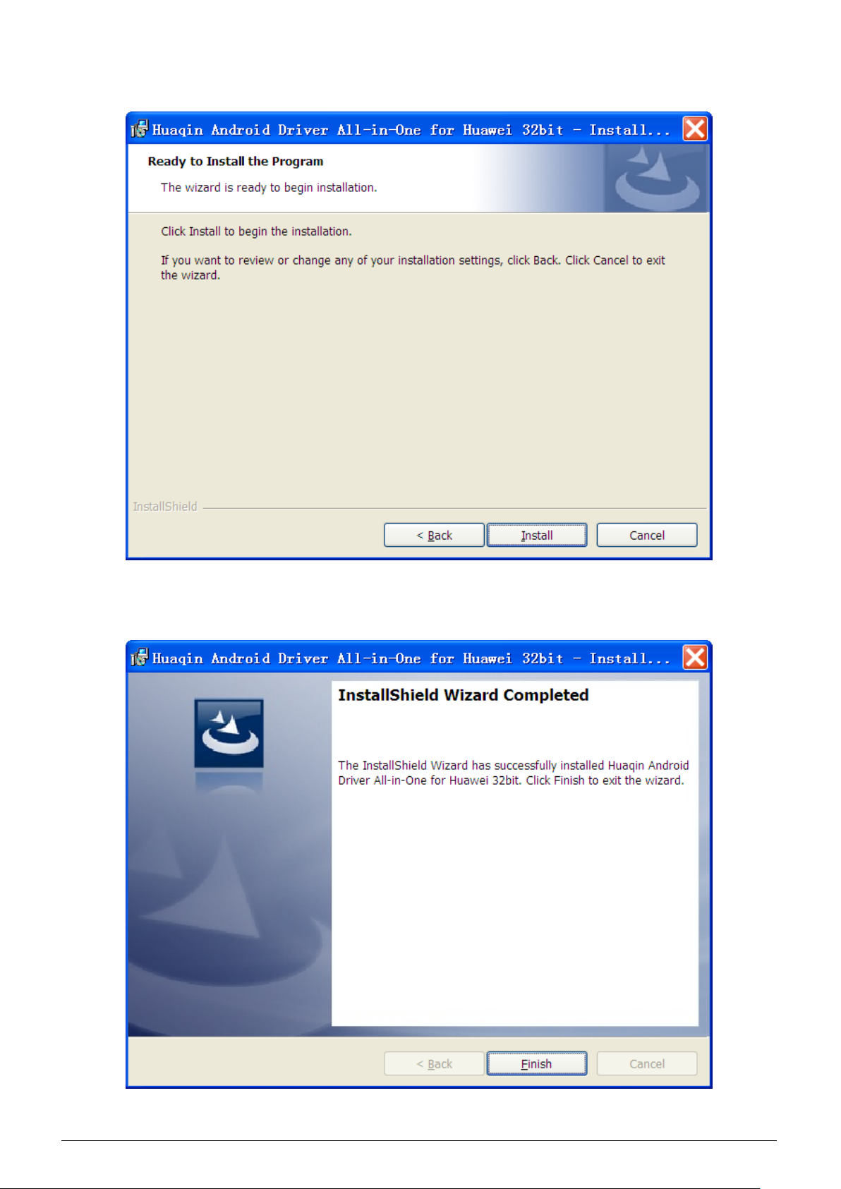
1.3. Click ―Install‖ button in the below picture to install driver.
1.4. Click ―Finish‖ button in the below picture to finish driver installation.
13

2. Download Preparation
Please scan port before user download software (Each port of each computer only needs
to operate one time). Note: When operating at the same time, only one port scanning (User can
scan multi ports sequentially).
2.1. Load Software
14

15
2.2 Scan Port
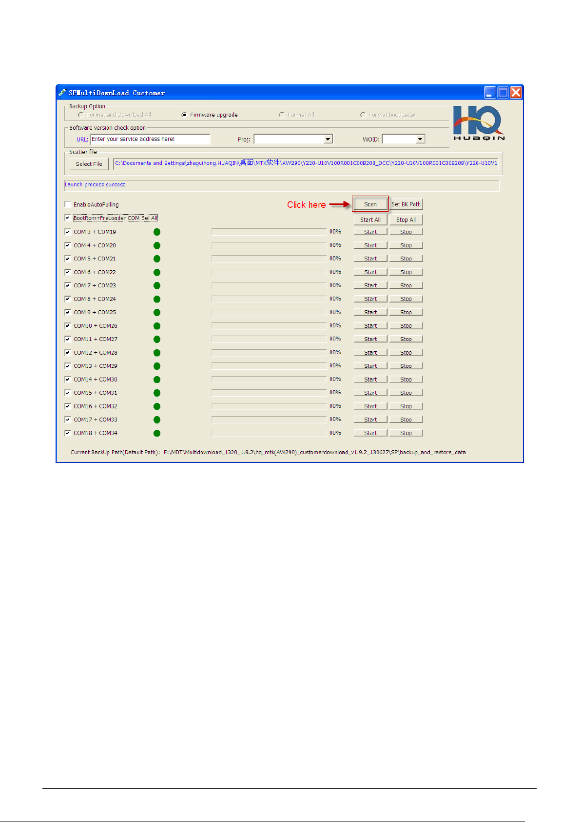
2.2.1 Click ―scan‖ button
16

17

2.2.2 At this time the user needs to keep pressing the volume up key and connect the USB
until to appear as shown in the following diagram can loosen the volume up key. Please
disconnect USB cable while scan success.
18

19

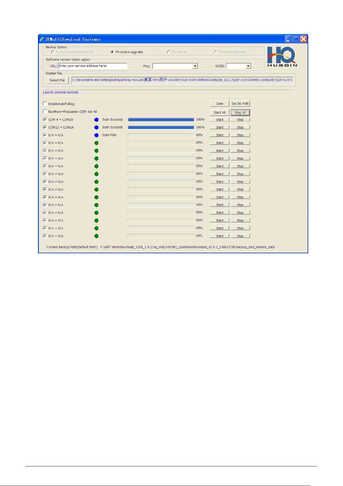
2.2.3 While the user needs to scan more ports, please change others port cable and
continue scan ports, operating method of the phone similar 2.2.2. When scan ports complete,
please click ―Stop All‖ to stop scan.
20
21
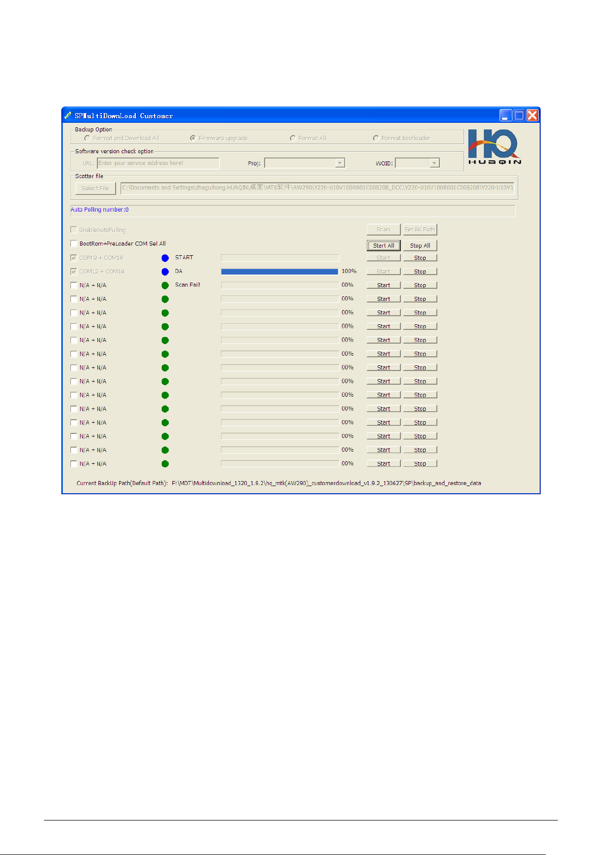
3. Download Process
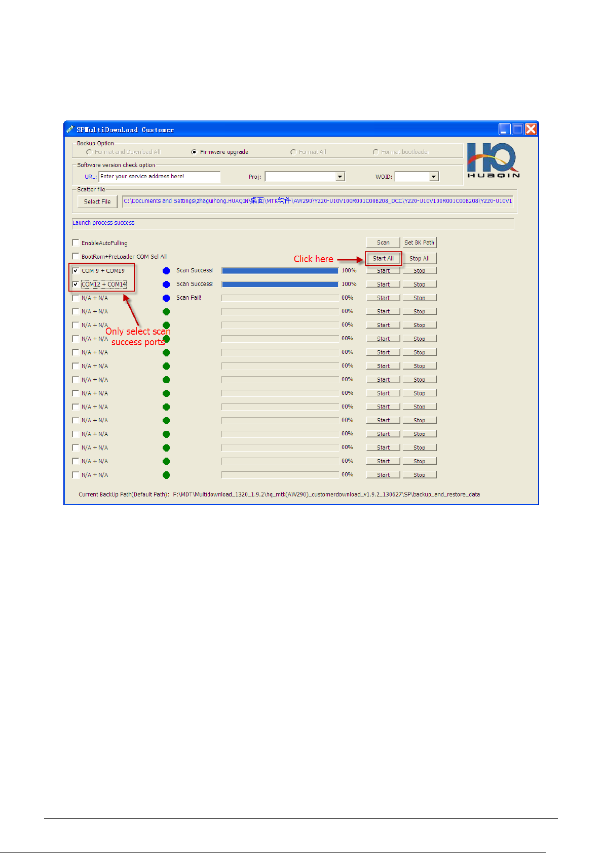
3.1. Only select scan success ports, then click ―Start All‖ button.
22
23
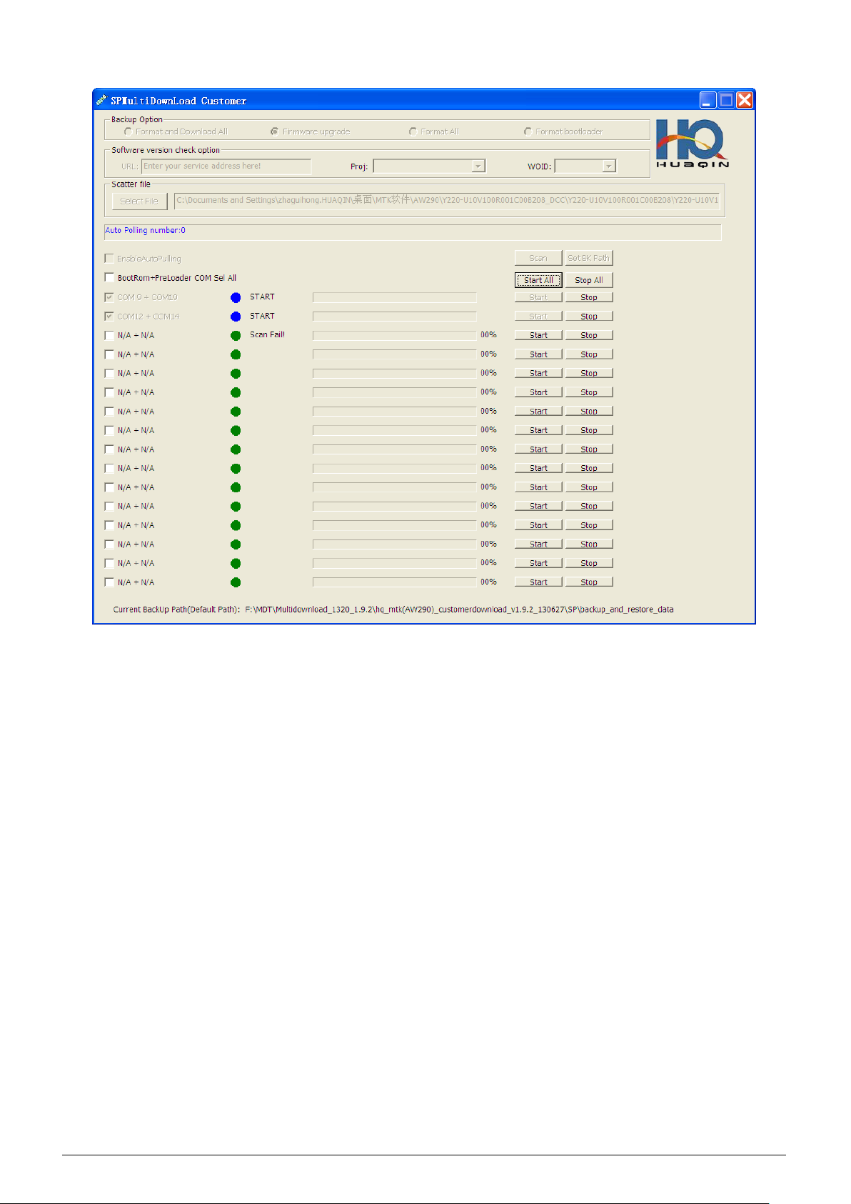
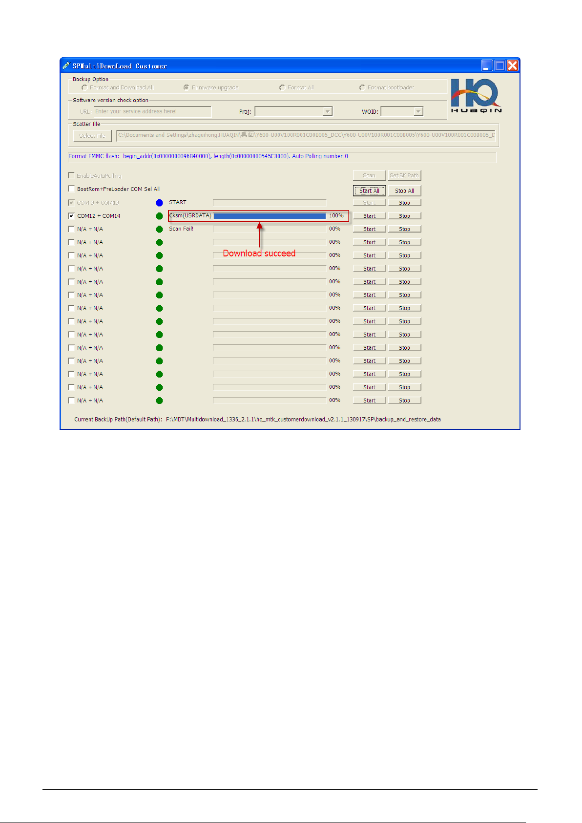
3.2 Operate phone, connect USB cable with phone in power off mode. Tool while auto start
download. While the tool interface show as ―Cksm(USRDATA)‖, the phone download software
succeed.
24
3.3 Disconnect USB cable with phone, then click ―Start All‖ button and change another phone to
continue download(Operate multi phone download at same time similar operate single phone).
25
 Loading...